

Page 1

DIGITAL RECORDING SYSTEM user manual
DIGITAL RECORDING SYSTEM
user manual
SPR-9816/9716
AB82-01978A Rev-00
imagine the possibilities
Thank you for purchasing this Samsung product.
To receive a more comprehensive service,
please register your product at
www.samsung.com/global/register
Page 2
key features of your DVR
The SHR-9816/9716 compresses up to 16 video input signals using an advanced MPEG4 codec and up to 16 audio input
signals using ADPCM for real-time simultaneous storage and playback from the hard drive. This unit is also capable of
streaming these signals across various networks for remote monitoring.
16-Channel BNC Video Input Connectors
NTSC/PAL Video Source Compatible
Recording speed: 480 ips (NTSC) / 400 ips (PAL) using CIF resolutions (352x240 NTSC / 352x288 PAL)
Supports hard drive overwrite mode.
Supports USB 2.0 backup devices.
Supports remote monitoring via Windows Network with SPR Smart Viewer.
Record and playback 16 audio channels.
Includes various recording options/triggers (continuous, motion, object watch, sensor, POS, video loss, and 1 ch. instant
recording)
Alarm Interface (Input: 16, Output: 4)
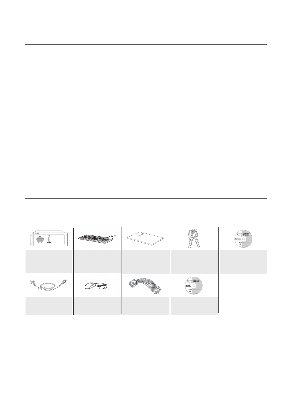
WHAT’S INCLUDED WITH YOUR DVR
Please ensure that the following components are included within the box. Contact your retailer if any of the components are
missing.
SPR Smart System
Power Cable
Keyboard
Mouse
User Manual
Audio Cable
Keys
System Recovery CD
SPR Smart Viewer
Program CD
Page 3

safety regulations
Please adhere to these safely regulations for the proper use of the product and to prevent risk/damage to you or
the unit.
Do not use more than one multi-plug.
Using too many multi-plugs can cause abnormal heat generation or fire.
Do not place sources of liquids near the DVR. ie: vases, cups, medicine, etc.
Liquids can present a fire hazard.
Do not bend the power cord forcibly nor put a heavy material on it.
This action could lead to a fire.
Do not operate or setup the DVR with wet hands.
This can cause a serious injury by an electrical shock.
Firmly insert the power plug into the socket so that it does not shake.
An imperfect connection presents a fire hazard.
Protect the DVR from humidity, dust, or soot.
They can cause a fire or an electric shock.
Do not put metals (coin, hair pin, metal piece, etc.) or inflammable materials (match, paper, etc.) in the
ventilation hole.
These obstructions can cause abnormal heat generation or fire.
Keep the surrounding temperature between 0°C to 40°C and keep the product off humidity.
Excessive temperatures can cause the DVR to malfunction.
Provide sufficient ventilation.
This will prevent abnormal operation due to high temperatures.
Keep the unit out of direct sunlight and away from any other sources of heat.
These sources of heat can cause abnormal heat generation or fire.
Do not disassemble, repair, or remodel the product.
This may cause fire, electric shock, or injury due to abnormal operation.
Do not pull out the power plug by the power cord.
This may destroy the power cord, eventually, cause fire or electric shock.
Unplug the unit during thunder or lightning.
The unit's components present a choking hazard. Contact a doctor immediately if a component has been swallowed.
An insecure DVR positioning can cause physical harm or damage to the unit.
A power surge can damage the unit.
Keep children away from the unit or it's components.
Install the product at a safe place so that there is no risk the DVR can be knocked or fall to the ground.
Page 4
before start
This user manual provides information that are necessary in the use of the DVR, ranging from a brief introduction of
the product to names, functions, and connection instructions of the components, menu configurations, and other
information pertinent to product use. Please read and adhere to the following notices.
SEC retains the copyright on this manual.
This manual cannot be copied without prior written approval from the SEC.
Samsung Electronics will not be held responsible for damages caused by the improper use of the product or the
use of non-specified equipment with the product.
If you want to open the case of your system for for any reason, please consult the installer or the retail outlet
which you brought the product.
Source codes are available for download at: http://www.samsung.com
Check compatibility before attempting to install any internal devices (memory, HDD).
A list of compatible devices can be obtained from your vendor.
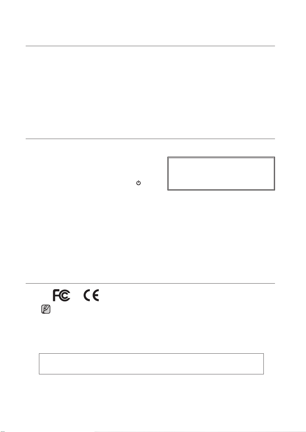
WARNING
System Shutdown
Turning off the power while the product is in operation,
or taking not permitted actions may cause damage to
the hard drive or the product. Also it can cause a
dysfunction to the system installed on the hard disk.
Please turn off the power using the Power ( /I)button
on the front of your DVR. After selecting OK in the
pop-up menu, you can pull out the power cord.
You may want to install a UPS system for safe operation in order to prevent damage caused by an unexpected
power surge/loss. (Any questions concerning UPS, consult a UPS retailer.)
Make sure that the mains plug is not covered or obstructed by any object.
The unit must be connected to an outlet with a protective ground connection.
CALIFORNIA USA ONLY
This Perchlorate warning applies only to primary CR (Manganese
Dioxide) Lithium coin cells sold or distributed with products in
California USA.
Special handling for perchlorate material may apply.
See www.dtsc.ca.gov/hazardouswaste/perchlorate
Operating Temperature
The operating temperature range of this product is 0°C to 45°C (32°F to 113 °F).
Operating the DVR outside the temperature range can cause the unit to malfunction.
If the unit was stored outside the operational temperature range, allow the unit to return to room
temperature before operating.
The HDD operating temperature is 5°C (41°F) to 55°C (131°F).
The HDD like the DVR may malfunction outside of these temperatures.
STANDARDS APPROVALS
This equipment has been tested and found to comply with the limits for a Class A digital device, pursuant
to part 15 of the FCC Rules. These limits are designed to provide reasonable protection against harmful
interference when the equipment is operated in a commercial environment.
This equipment generates, uses, and can radiate radio frequency energy and, if not installed and used
in accordance with the instruction manual, may cause harmful interference to radio communications.
Operation of this equipment in a residential area is likely to cause harmful interference in which case the
user will be required to correct the interference at his own expense.
The rechargeable battery incorporated in this product is not user replaceable.
For information on its replacement, please contact your service provider.
Page 5

contents
INTRODUCING YOUR REAL TIME DVR
03
INSTALLATION
05
CONNECTING WITH OTHER DEVICES
06
WATCH
13
03 DVR: Front View
04 DVR: Rear view
05 Installation
06 Basic connections
07 Sensor connection
08 Alarm connection
09 RS485 Connection
10 Network connection
11 External keypad connection
12 Pos device connection
13 Live watch screen
14 Login screen
14 Camera channel
15 Database drive allocation
16 Resource/ptz/playback/log
18 Full screen
19 Live screen switch
20 1-Channel video playback
20 Camera channel assignment
21 ON-Screen keyboard
SYSTEM SETUP
21
SEARCH
52
21 System setup - Basic menu
22 Hardware
29 Recording
32 Event
38 Backup
39 Network
43 System
52 Search screen
53 Search date and time selection
53 Timeline
54 Search screen playback
54 Split-scren setupt
54 Screen adjustment
57 Event search
57 Printing
contents _01
Page 6

ADVANCED SEARCH
58
58 Event search
59 Sequential search
60 Thumbnail search
61 Object search
62 Pos search
BACKUP
63
APPENDIX
65
63 Backup
64 Backup management
65 System recovery
67 WebDVR
70 SPR Smart viewer
77 Remote desktop control
78 Specifications
79 Outline drawings
80 Troubleshotings(FAQ)
02_ contents
Page 7
introducing your real time DVR
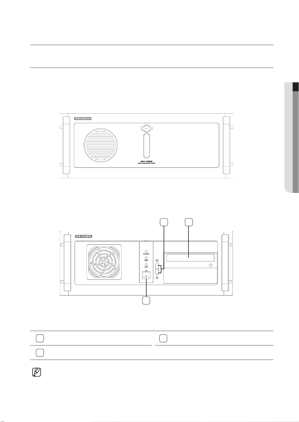
DVR: Front View
With the Panel Closed
01 INTRODUCING YOUR REAL TIME DVR
With the Panel Open
2
1
1
3
Front and rear configurations of the system may change to reflect changes in specifications or other quality
improvement purposes.
Power
DVD-RW
2
3
USB
introducing your real time DVR_03
Page 8
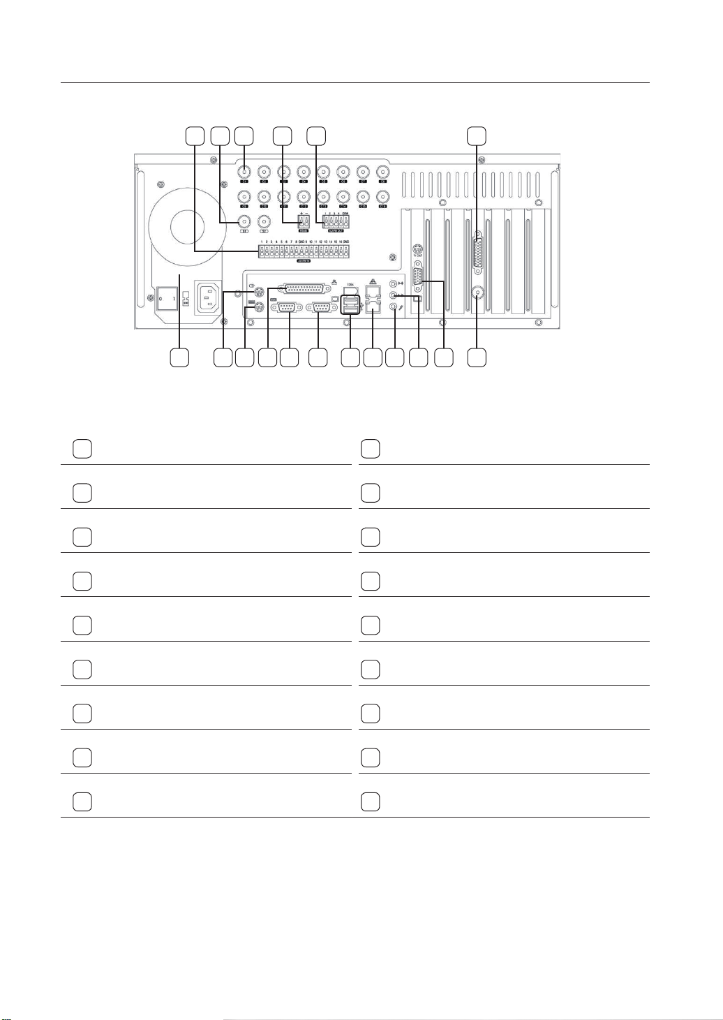
DVR: Rear View
32 5 6
1
1
Power Supply (AC 100-240V, 60/50Hz, 4A/2A)
3
Spot Monitor Out Ports (2 ports)
5
RS485 Port
74
11 14 17 189 10
138 12 15 16
2
Sensor Input (Alarm-In) Ports (16 ports)
4
Camera Video Input Ports (16 ports)
6
Alarm-Out Ports (4 ports)
7
Audio Input Port
9
Keyboard Input Port (PS/2)
11
COM Port (COM1)
13
USB Port (Ver. 2.0)
15
Microphone Input Port (two-way audio input)
17
VGA Port
04_ introducing your real time DVR
8
Mouse Input Port (PS/2)
10
Printer Port (LPT1)
12
Internal VGA Port
14
Ethernet Port (100 Mbps)
16
Audio Output Port (speaker connection port)
18
Spot Monitor Out Port (supports 16-screen)
Page 9
installation
CHECKING INSTALLATION CONDITIONS
Adhere to the following precautions when installing the
unit.
• Indoor use only.
•Prevent water and liquids from coming in contact with
the unit’s terminals.
Protect the unit from excessive impact and force.
•
Do not forcibly pull on the power cable.
•
Do not open or disassemble the unit.
•
Use within the rated power input/ output range only.
•
• Use an approved power cable only.
For products that require a ground source always use
•
a plug that includes a ground pin.
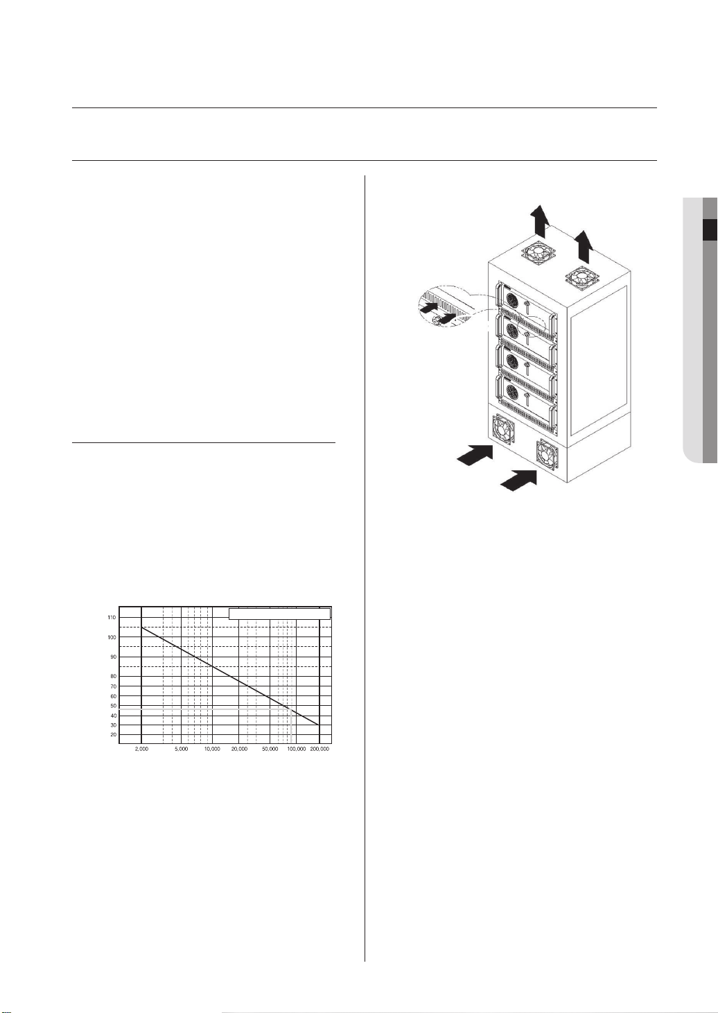
TEMPERATURE CONDITIONS
Samsung's Digital Video Recorder is an advanced
security system that contains a high-capacity hard
drive and other critical circuitry.
Carefully follow the installation instructions to prevent
high internal or ambient temperatures, which can
lead to a shortened lifespan or malfunction of the
unit.
Temperature
Unit: ºC
One Year: 24HR X 365 DAY =8,760 HR
Life (Unit: HOURS)
[Graph: Correlation between Temperature and Product
Lifespan]
Recommendations for Mounting into a Rack
1. The inside of the rack must not be enclosed.
2. The rack must feature ventilation ports to provide
3. Allow sufficient space between the DVR unit and
4. Install the intake ports at the bottom of the
5. SEC strongly recommends the installation of fans
6. An ambient temperature range of 0˚C to +45˚C
02 INSTALLATION
sufficient internal air circulation, as shown in the
diagram above.
other modules mounted to the rack or install
ventilation ports to facilitate air circulation, as
shown in the diagram.
rack and exhaust ports at the top of the rack to
facilitate the formation of a natural convection
airflow.
at both intake and exhaust ports. Intake fans
should be installed with a filter to block dust and
other foreign materials.
must be maintained inside the rack.
installation _05
Page 10
06_ connecting with other devices
connecting with other devices
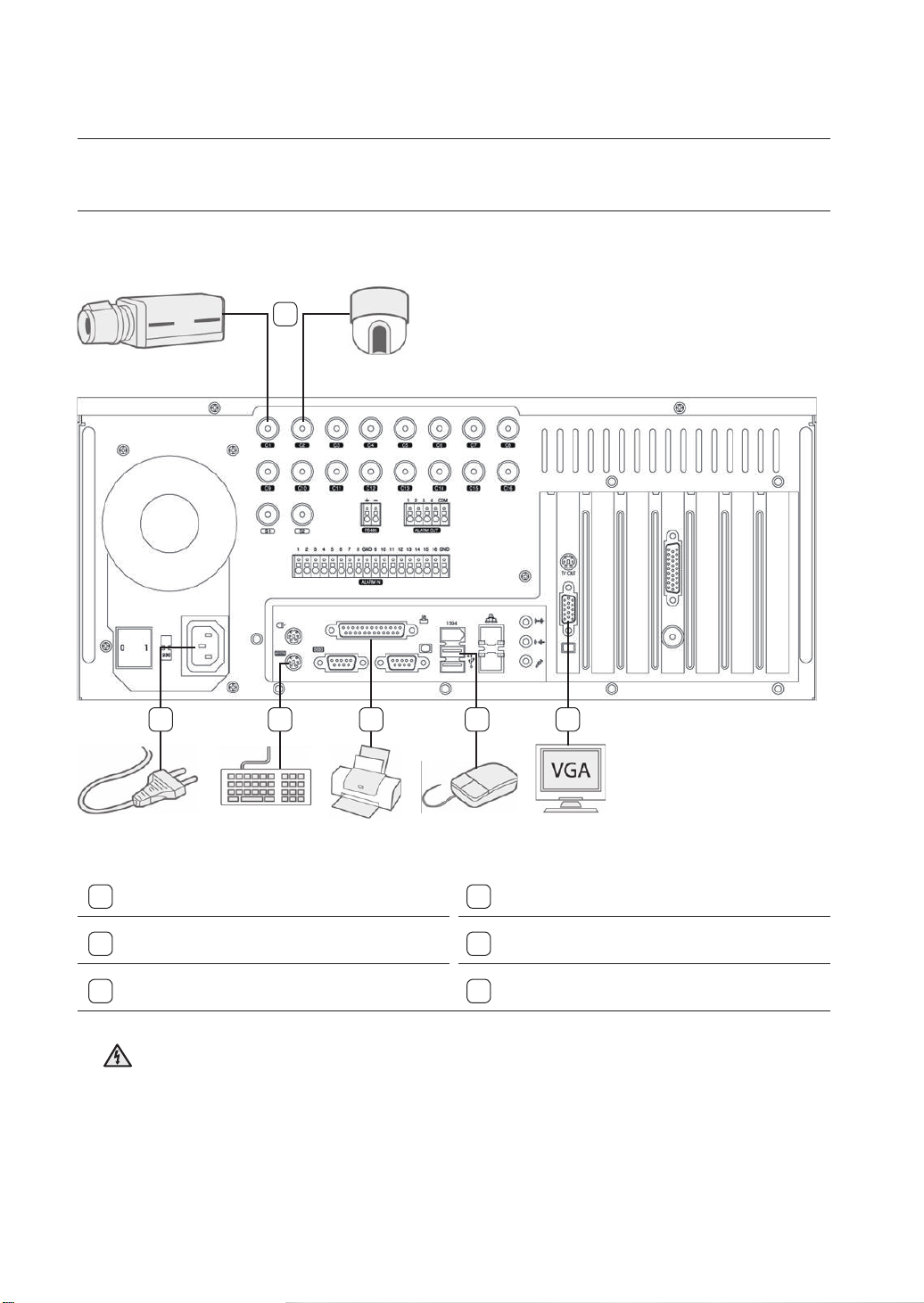
BASIC CONNECTION
1
2 3 4 5 6
Using a coaxial cable, connect a camera(s) to
1
the BNC port(s).
3
Connect a keyboard to the PS/2 port.
5
Connect a mouse to a USB port.
Ensure the correct rated voltage is provided before powering the unit. Improper voltage may cause
Warning
malfunction and/or permanent damage to the system.
Electrical Hazard: Please carefully read through the Safety Warnings and Precautions section.
Attach the appropriate power cord to the
2
power supply unit.
4
Connect a printer to the LPT1 port.
6
Connect a VGA monitor to the VGA port.
Page 11
02 CONNECTING WITH OTHER DEVICES
connecting with other devices _07
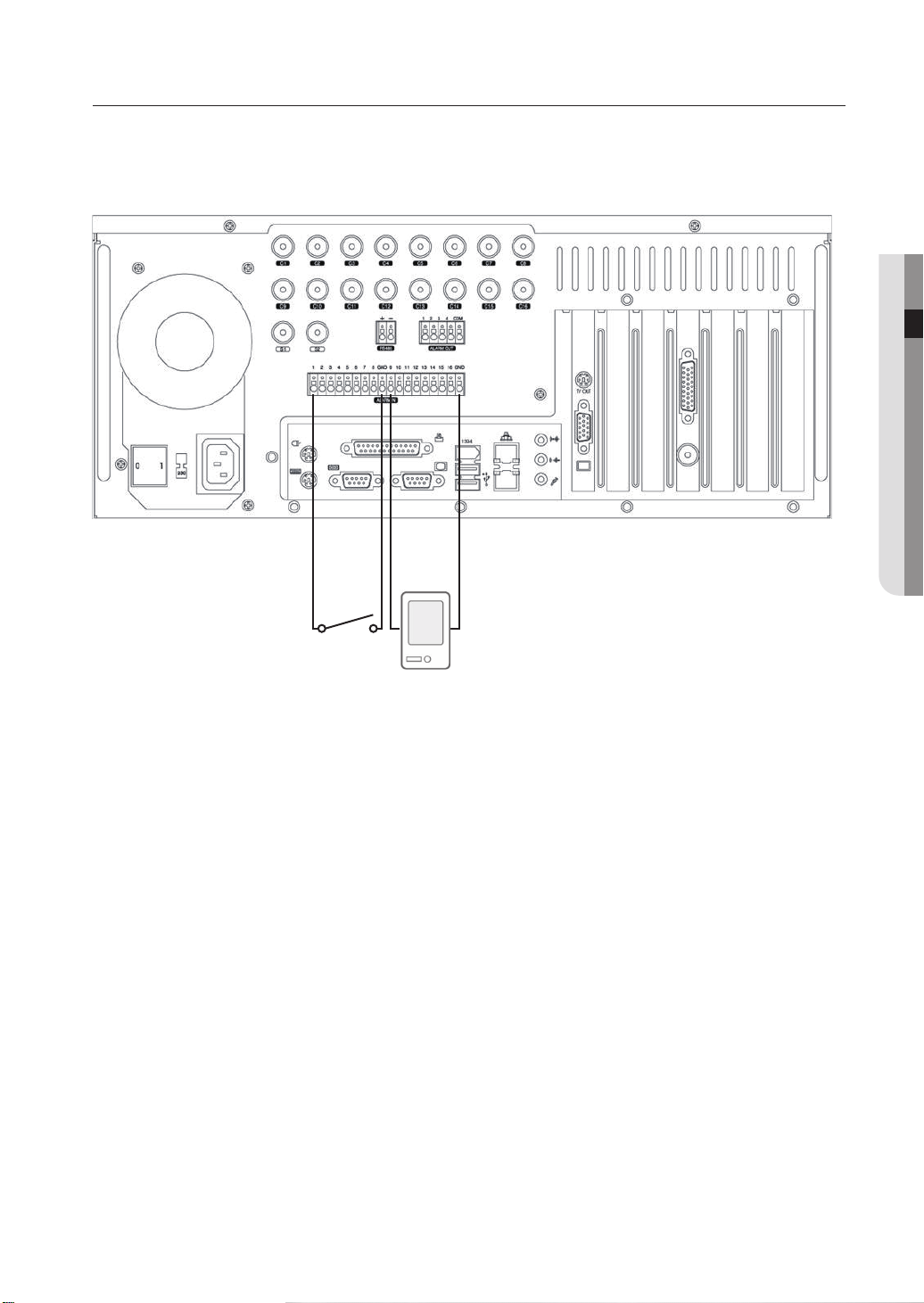
SENSOR (ALARM-IN) CONNECTION
(Alarm-In)
GNDNo.1 Sensor
(Alarm-In)
GNDNo.9 Sensor
Your DVR system is capable of transmitting electrical signals to external devices when an event occurs. Mechanical
or electrical switches can be connected to the Alarm-In and Ground (GND) ports. The individual Alarm-In ports can
be configured from the System Setup menu as either NC (Normal Close) or NO (Normal Open).
Alarm-In Connection
1. Connect one of the external device’s signal lines to the desired Alarm-In port.
2. Connect the remaining line to the Ground port (GND).
Page 12
08_ connecting with other devices
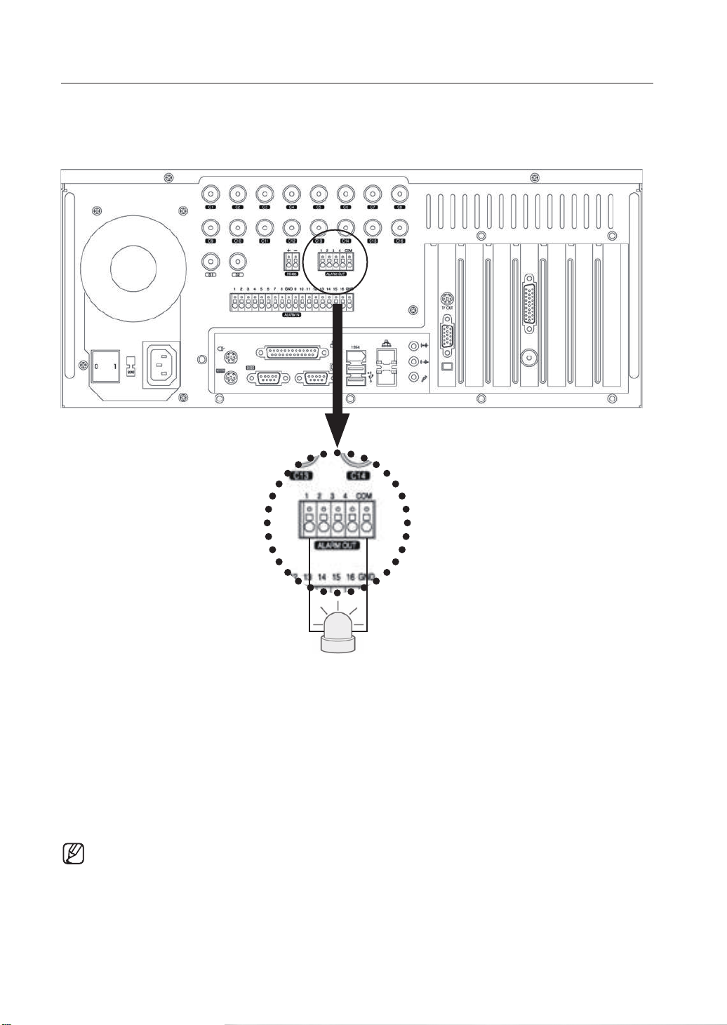
ALARM (ALARM-OUT) CONNECTION
Your DVR system is capable of activating warning lights, sirens, and other types of external devices.
External device s can be connected to the unit's Alarm-Out and COM ports.
Alarm Connection
1. Connect one of the external device's signal lines to the desired alarm (Alarm-Out) port.
2. Connect the remaining line to the COM port.
• The alarms (Alarm-Out) operate in conjunction with the sensors (Alarm-In). When an event signal is
received through a sensor, an electrical signal is transmitted from the corresponding alarm to activate
the external device connected to that alarm.
• Alarms can be configured to function in unison with motion detection, video loss, object detection, and
other software features.
Page 13
02 CONNECTING WITH OTHER DEVICES
connecting with other devices _09
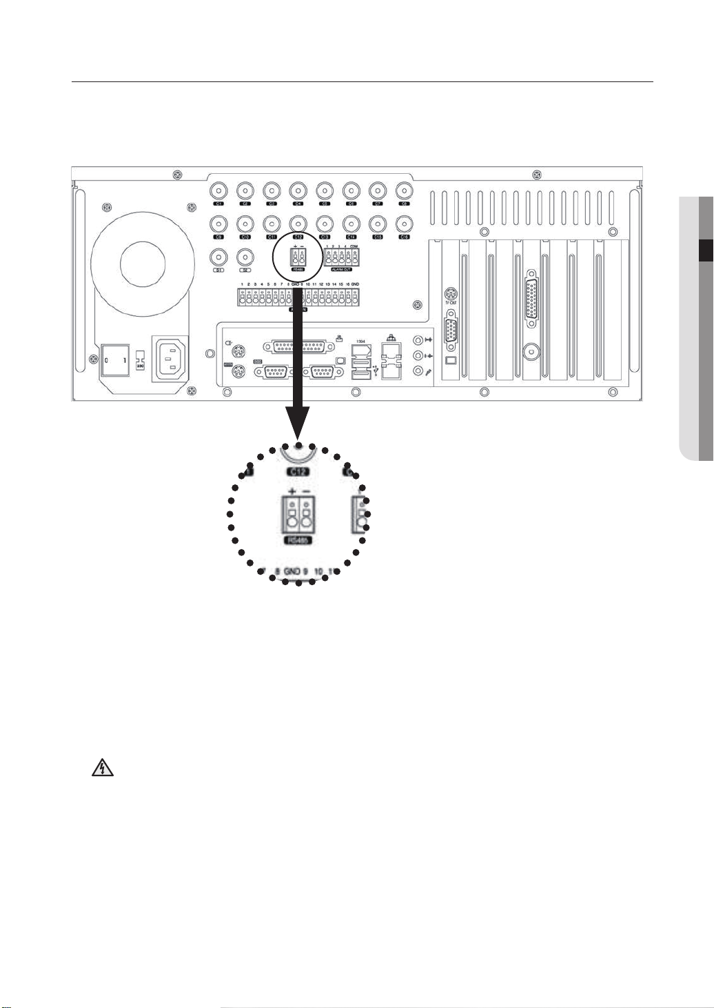
RS485 CONNECTION
It's possible to control an external device by the DVR using the RS485 interface for communication.
The RS485 port can be used to control PTZ cameras, speed domes, keyboard controllers and other types of external
devices.
Connect the RX+/TX+ & RX-/TX- of the external device to the + & - of the RS485 port respectively.
Check the polarity (+/-) when making the connection. Faulty wiring can damage both devices.
Electrical Hazard: Please carefully read through the Safety Warnings and Precautions section.
Warning
It’s not possible to connect a PTZ device and a keypad device (SSC-2000) to the RS485 port and use the two
devices at the same time. In order to use a PTZ device with a keypad or another type of external device, you
will need to install a separate COM port expansion card.
Page 14
10_ connecting with other devices
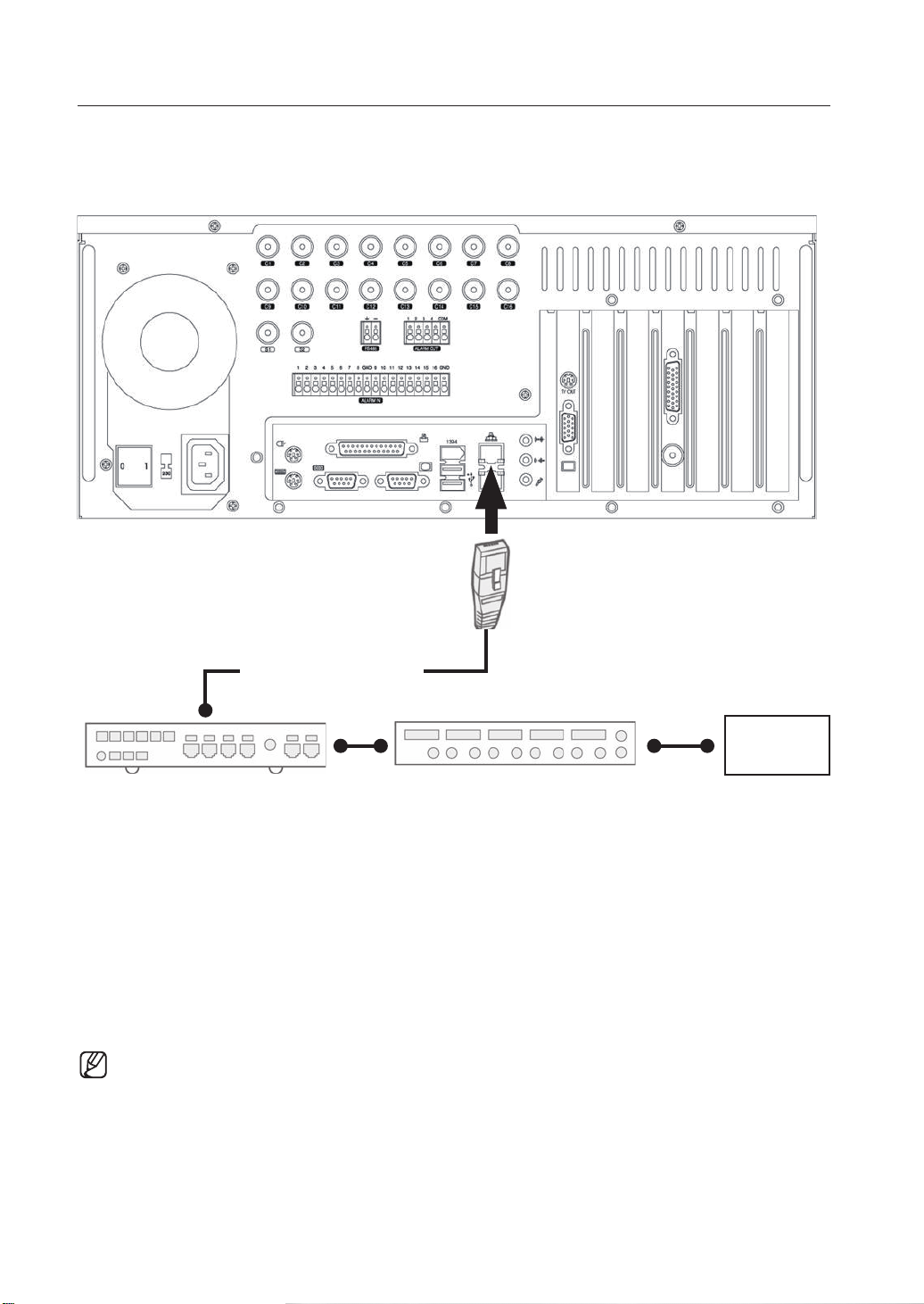
NETWORK CONNECTION
Ethernet/UTP Cable (CAT5)
LAN/WAN
Internet
Switch Hub (100Mbps) Router
Your DVR system supports network-based remote monitoring, remote search, remote control, and remote software
upgrade. SEC recommends the use of the TCP/IP protocol and a switching hub for LAN/WAN applications.
Network Cable Connection
1. Connect a Ethernet/UTP cable to the network port located at the rear of the system.
2. Connect the opposite end of the Ethernet/UTP cable to the switch hub.
• Before connecting your DVR system to the network, please contact your network administrator to
prevent the system from causing a network conflict.
Page 15
02 CONNECTING WITH OTHER DEVICES
connecting with other devices _11
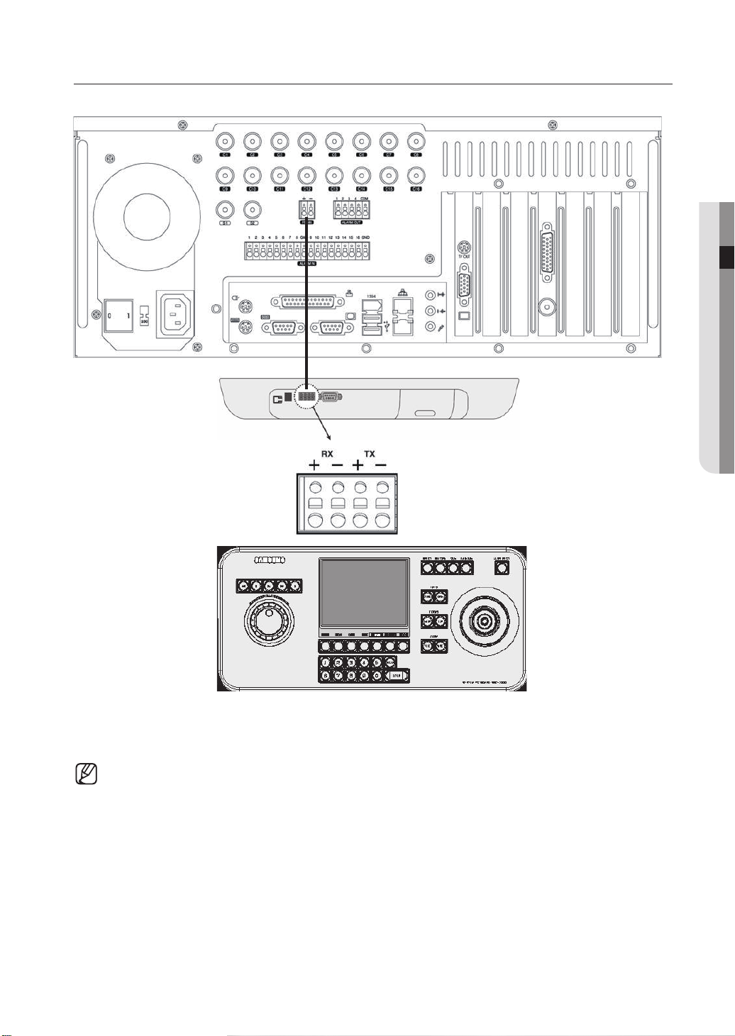
EXTERNAL KEYPAD CONNECTION
The SSC-2000 keypad can be used to control up to 255 DVR and PTZ units.
Connect the DVR's RS485 (+/-) port to the SSC-2000 keypad's RS485 port.
• Turn the power off both units while connecting the SSC-2000.
• Pay attention to the polarity of the RS485 connections.
• Refer to the SSC-2000 manual when attempting a RS232 connection.
• When using a keypad device, please ensure that communication settings for both the DVR and the
keypad device are the same. Communication settings mismatch can prevent the keypad device and the
DVR from making normal communication. (Set communication protocols for both the keypad and the
DVR as Half Duplex.)
It’s not possible to connect a PTZ device and a keypad device (SSC-2000) to the RS485 port and use
•
the two devices at the same time. In order to use a PTZ device with a keypad or another type of external
device, you will need to install a separate COM port expansion card.
Page 16
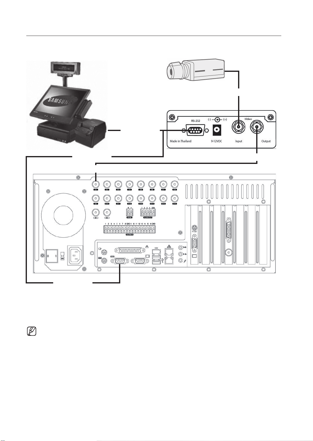
POS DEVICE CONNECTION
Camera
Video Input
RS232C Cable
POS System
RS232C Cable
Video Input
RS232C Cable
V SI-PRO(Text Input Device)
Video Output
Your DVR system is capable of operating in conjunction with POS systems, enabling you to store and search video
transactions at the point of sale. AVE’s VSI-PRO is needed to connect the POS device to the DVR.
For details on connecting VSI-PRO with your DVR, please refer to VSI-PRO’s user manual.
• VSI-PRO by AVE (www.americanvideoequipment.com) is a device that transmits all text data received
from POS device to the DVR via the RS232C interface.
• Turn off the power to all devices when connecting the POS device, VSI-PRO, and the DVR.
12_ connecting with other devices
Page 17
watch
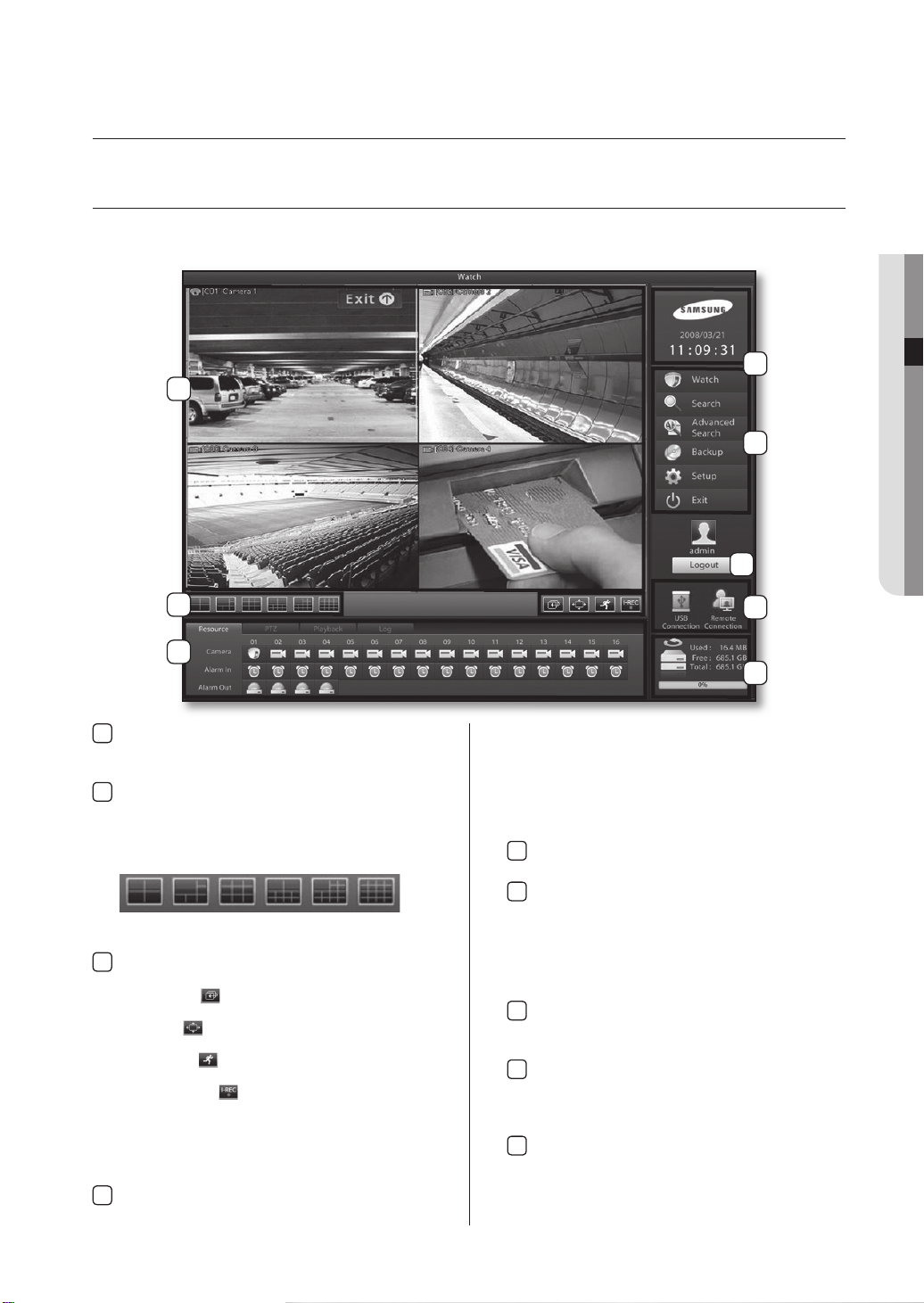
LIVE WATCH SCREEN
Live Watch supports full screen and various split-screen confi gurations. From Live Watch, you will be able to control PTZ, perform 1ch
instant playback and make a backup. The buttons located within the watch screen also provide access to the other menus.(search,
setup, etc).
5
1
6
7
03 MONITORING
2
4
Video Display Window
1
Displays the live video feeds on screen. Simply drag
and drop a camera channel to move a video feed.
Split-screen Buttons
2
These buttons indicate 4-, 6-, 9-, 10-, 13-, and
16-split screen modes. Continue clicking on the
same mode to sequentially cycle through the
other camera channels in the same split.
4-
6
-
9
-
10
-
13
-
16
Screen
Screen
Screen
Screen
Screen
Switch Screen/Full Screen/Switch to Live/In-
3
-
Screen
stant Recording.
Switch Screen(): Automatically cycles through the
Full Screen(): Expands the video feeds to a full screen
Switch to Live(): Reverts a 1-channel playback screen
Instant Recording(): Starts the instant recording of the
Resource/PTZ/Playback/Log
4
Resource: Select and view the status of cameras,
video feeds.
view.
back to the live feed screen.
selected channels. In the event
of an emergency, clicking on this
button initiates selected camera
channels to start continuous
recording
8
9
sensors, alarms, and other devices
PTZ: Displays PTZ controls.
Playback: Displays the controls for 1 channel
Log:
Clock
5
connected to the DVR.
playback.
Displays information on the 100 most recent events
that have transpired during DVR system operation.
Displays the current time of your DVR system.
Menu Buttons
6
Watch: Accesses the Live Watch screen.
Search: Accesses the Search screen.
Advanced Search: Accesses the Advanced Search screen.
Backup: Accesses the Backup screen.
Setup: Accesses the System Setup screen.
Exit: Terminates the DVR program/system.
Login/Logout
7
Launches the login window for user ID and password entry.
USB Connection and Remote Connection
8
Displays the connection status of the USB storage device and the connection status of a remote
PC. Blue icon indicates a connected status.
Hard Drive Capacity
9
Displays the total hard drive space of the system,
the amount of space used, and the amount of
space available.
monitoring _13
Page 18
14_ monitoring
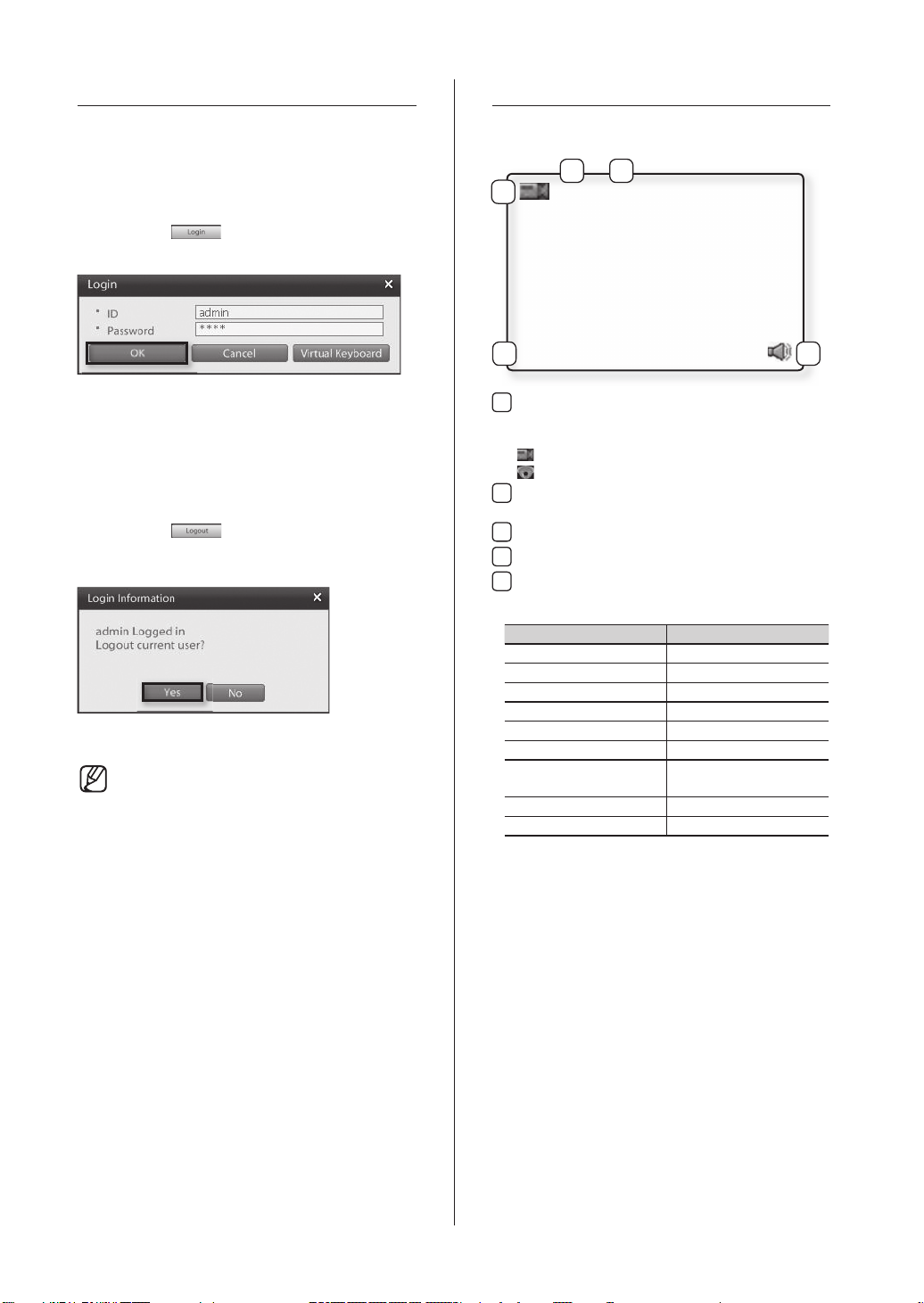
LOGIN SCREEN
CAMERA CHANNEL
Entering authorized user ID and password gives access to
search features, system setup, and other system functions.
Entering an incorrect user ID and password, however, will
result in limited DVR functionality and control access.
Logging In
1. Click on the button.
2. Enter the user ID and password.
3. Click OK to login.
Logging Out
1. Click on the button.
2. Login information window will prompt displaying
information about the active login account.
3. To log out from this user click the Yes button.
• From the factory, the default admin
password is set as 4321.
• Admin account password cannot be
changed without knowing the current
admin account password; therefore,
it is important that you do not lose it.
Administrators should separately record
and manage their registered password.
Camera Channel Display Icons
2 3
1
4
1
2
3
4
5
[C01] CAMERA01
REC : M
Camera Type
Indicates whether the camera is a normal camera or
a PTZ camera.
: Indicates a normal camera.
: Indicates a PTZ camera.
Channel Number: Indicates the channel number of
the camera.
Camera Designation: Displays the camera’s designation.
Recording Mode: Displays the camera’s recording Mode.
Live Audio: Indicates that audio output has been
activated for the channel.
Recording Modes On Screen Indication
Not Recording No Indication
Continuous Recording REC: C
Motion Recording REC: M
Object Detection REC: W
Recording REC: S
Sensor (Alarm-In) REC: P
PreAlarm Recording
POS Recording
Instant Recording REC: I
Video Loss REC: L
REC: $
5
Page 19
03 MONITORING
monitoring _15
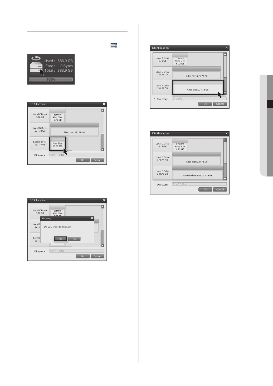
DATABASE DRIVE ALLOCATION
Allocating a New Database Drive
1.
Login as an administrator then double click on the icon.
2. You will then be prompted with the Database Drive Allocation window.
3.
Left-click on a non-allocated drive (Free Size) and you will
be prompted with a "Do you want to format?" warning
window. Click the Yes button to initiate formatting and
the allocation of a new database drive.
Disabling an Allocated Database Drive
1. Right-click on the allocated drive you wish to disable.
The drive color will turn from blue to grey.
2. Click OK to disable the allocated drive.
The drive color will turn red.
3. Right-clicking on the disabled database drive will place
the database drive in free status. Free status drives may
contain data, but this data will not be recognized as
database data.
Page 20
16_ monitoring
Reallocating a Disabled Drive
1. Left-click your mouse on a disabled database drive
and you will be prompted with a “Do you want to
format?” warning window.
2. Click Yes to initiate formatting or No to bypass
formatting. The drive will then be reallocated as a
database drive.
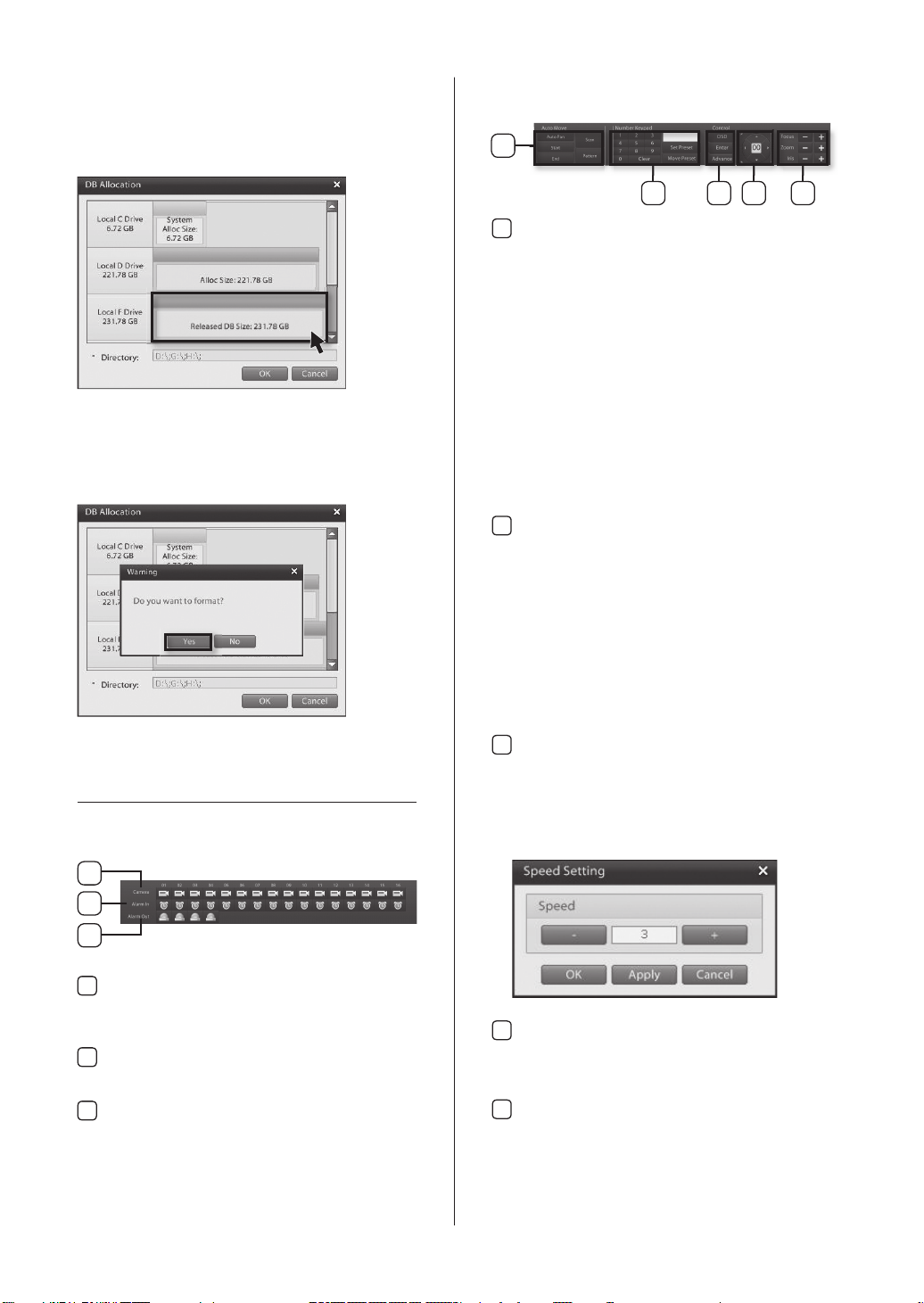
RESOURCE/PTZ/PLAYBACK/LOG
Resource Tab
PTZ Tab
1
2 3 4 5
Auto Move
1
Automated PTZ movement functions.
Auto Pan: This button is used to initiate Auto
Pan. AutoPan is a function where, after
designating the start point and end
point, the camera completes pan/tilt
trips within the defi ned interval.
Start: Starting position for the Auto Pan.
End: Ending position for the Auto Pan.
Scan: Seeks out presets containing PTZ position
data and moves to the position stored in
memory.
Pattern: Memorizes observation trajectories
initiated by the user and then
automatically moves the camera in the
same pattern and speed.
Preset
2
Enables the user to define Pan/Tile positions and
Zoom/Focus settings under Preset IDs that can
be used on demand. The number of supported
presets varies depending on the PTZ model. The
system supports up to the number of presets
supported by the PTZ itself.
Numeric Keypad: Use to enter Preset numbers.
Set Preset: Use to assign a PTZ camera position
to a specified Preset ID.
Move Preset: Moves the PTZ camera to the
position specified by a Preset ID.
Control
3
OSD: Accesses the PTZ camera's OSD menu.
Enter: Confi rms selections in the PTZ camera's
OSD menu.
Advanced: Accesses the PTZ camera's speed
confi guration window.
1
2
3
Camera
1
Displays the camera status. Drag and drop a
camera icon to the live screen to view the video
feed from that camera.
Alarm in
2
Displays the alarm-in status. A triggered channel
will turn red.
Alarm out
3
Displays the alarm-out status. An activated alarm
will turn red.
Directional Pad
4
Controls the vertical, horizontal, and diagonal
movement of the PTZ camera. Also used to
navigate in the PTZ camera's OSD menu.
Focus/Zoom/Iris
5
Controls the PTZ camera's focus, zoom, and
iris.
Page 21
03 MONITORING
monitoring _17
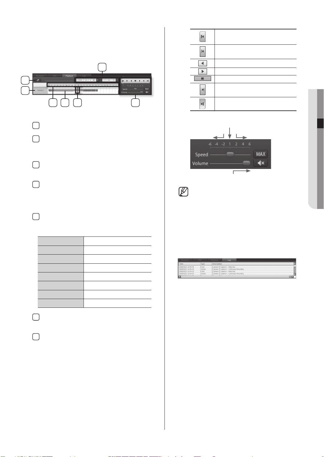
Playback Tab
Click on the Playback tab to access recording
timelines and recording playback controls for 1ch
playback.
3
1
2
5 7
4 6
Refresh
1
Refreshes the timeline to the latest recording data.
Camera
2
Displays the selected video channel. Selecting the
camera will display the corresponding time line
data.
Date & Time Selection
3
Select the desired year, month, and date to
search.
Timeline
4
Timeline features fi ve levels of zoom. The zoom
feature can be used view the time line in more
detail. Left-click on the timeline to zoom-in. Rightclick on the time line to zoom-out.
Recorded Data Time line
5
Displays recording times and types in a colored
time line.
Orange Continuous Recording
Blue Motion Recording
Grey
Green Alarm in Recording
Yellowish Green PreAlarm Recording
Dark Blue ATM/POS Recording
Yellow Video Loss
Purple Instant Recording
Object Detection Recording
First recorded Data
Single Frame Reverse
Reverse Playback
Forward Play
Stop
Single Frame Forward
Last recorded Data
1X
Playback
FastSlow
Maximum
Speed
Mute
High Volume
• Audio output is only available for 1x
forward playback.
Log Tab
Clicking on the Log tab accesses event
detection details, such as recording type
(continuous, motion, object detection, PreAlarm,
and POS) and network connection status.
Timeline Bar
6
Identifies the location of the desired timeframe you
wish to search. Click the bar to the desired time.
Playback Controls
7
Controls the direction and speed of the video
playback.
Page 22
18_ monitoring
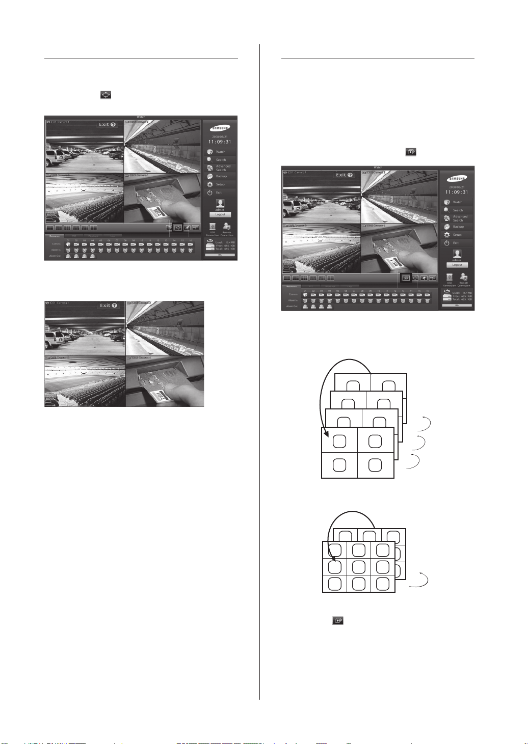
FULL SCREEN
LIVE SCREEN SWITCH
Switching to Full Screen
1. Click on the button to expand the live video to
full screen.
2. You now have full screen view of the live video
feeds.
This feature enables you to fl ip through different
camera feeds. If all camera feeds are not visible on
a single screen, use this feature to fl ip through and
view the remaining channels in sequence.
Sequencing Button
1. Select a single-screen or a 4-, 6-, 9-, 10-split
screen, mode then click on the button.
2.
The system will cycle through video feeds while
maintaining the selected display mode.
3. Click on the left mouse button to end full screen
display.
13 14
9 10
5 6
1 2
3 4
4-Channel Split Screen
5~6
1~4
10 11 12
1 2 3
4 5 6
7 8 9
9-Channel Split Screen
3.
Click on the button to stop the cycling.
15
18
1~4
13~16
9~12
10~18
Page 23
03 MONITORING
monitoring _19
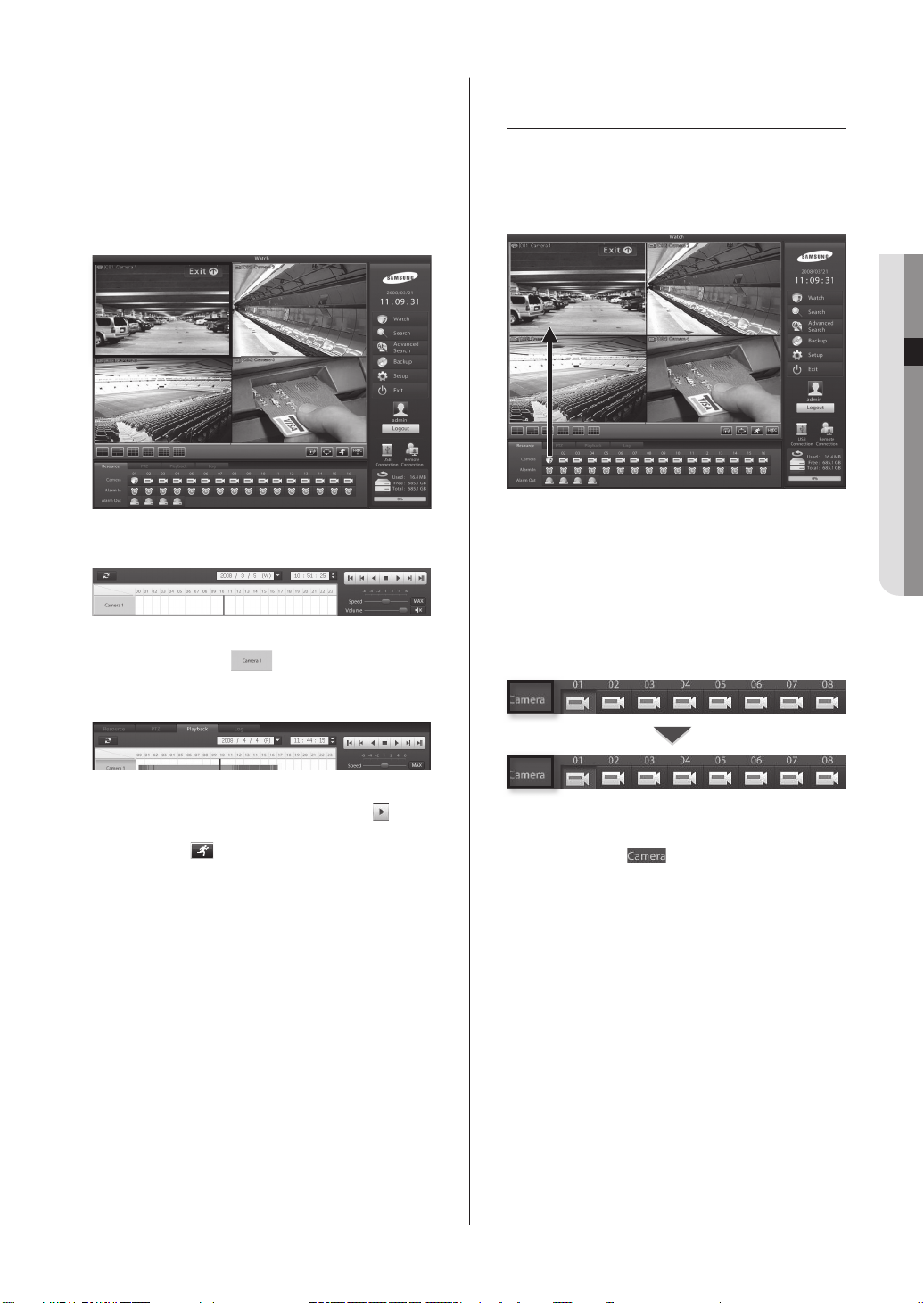
1-CHANNEL VIDEO PLAYBACK
Instant 1-channel playback of the selected channel
while monitoring others on live video feed.
1-Channel Playback
1. While monitoring, select a camera feed you wish to
playback.
2. Click on the Playback tab.
3. Click on the camera button.
4. The recording time line data of the selected
channel will be displayed.
CAMERA CHANNEL
ASSIGNMENT
Assigning a Camera Channel
1. Click on a camera button using your mouse and
drag to the live screen.
2. After dragging to live screen drop over the desired
location on live screen to assign that channel.
Reset the video feed layout
The camera designations will turn from white to
brown if reassigned video channels are preventing
other channels from being displayed or if the video
channel sequence is mixed up.
5. Select the playback time and click on the
button to start playback.
6. Click on the button to exit the 1-channel
playback.
1. To reset the cameras to their default locations
double-click on .
Page 24
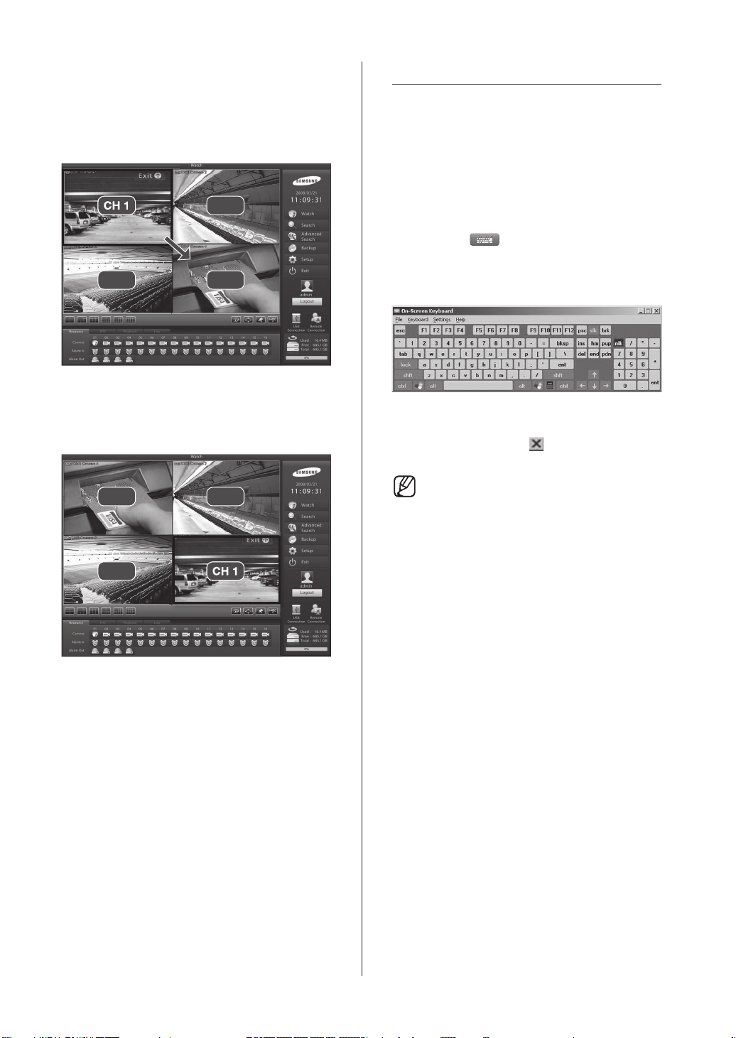
Moving Camera Picture Via View
CH 1
CH 1
Panel
1. Click on a video feed and drag to the desired
location.
ON-SCREEN KEYBOARD
A virtual keyboard can be displayed on screen.
This On-Screen Keyboard allows the user to
directly enter text using the mouse when there is
no keyboard attached to the DVR system or when
using a keyboard is not a viable option.
CH 1 CH 2
CH 3 CH 4
2. Release the mouse button over the desired
location to complete the camera feed movement.
CH 4 CH 2
CH 3 CH 1
Launching the On-Screen
Keyboard
1. Click on the button to launch the virtual
keyboard.
2.
Using your mouse, click on the characters of the virtual
keyboard to make key entries.
3. To terminate On-Screen Keyboard, either click on File
then select Exit or click the button.
• The virtual keyboard supports only the
English language option.
20_ monitoring
Page 25
System Setup
SYSTEM SETUP - BASIC
MENU
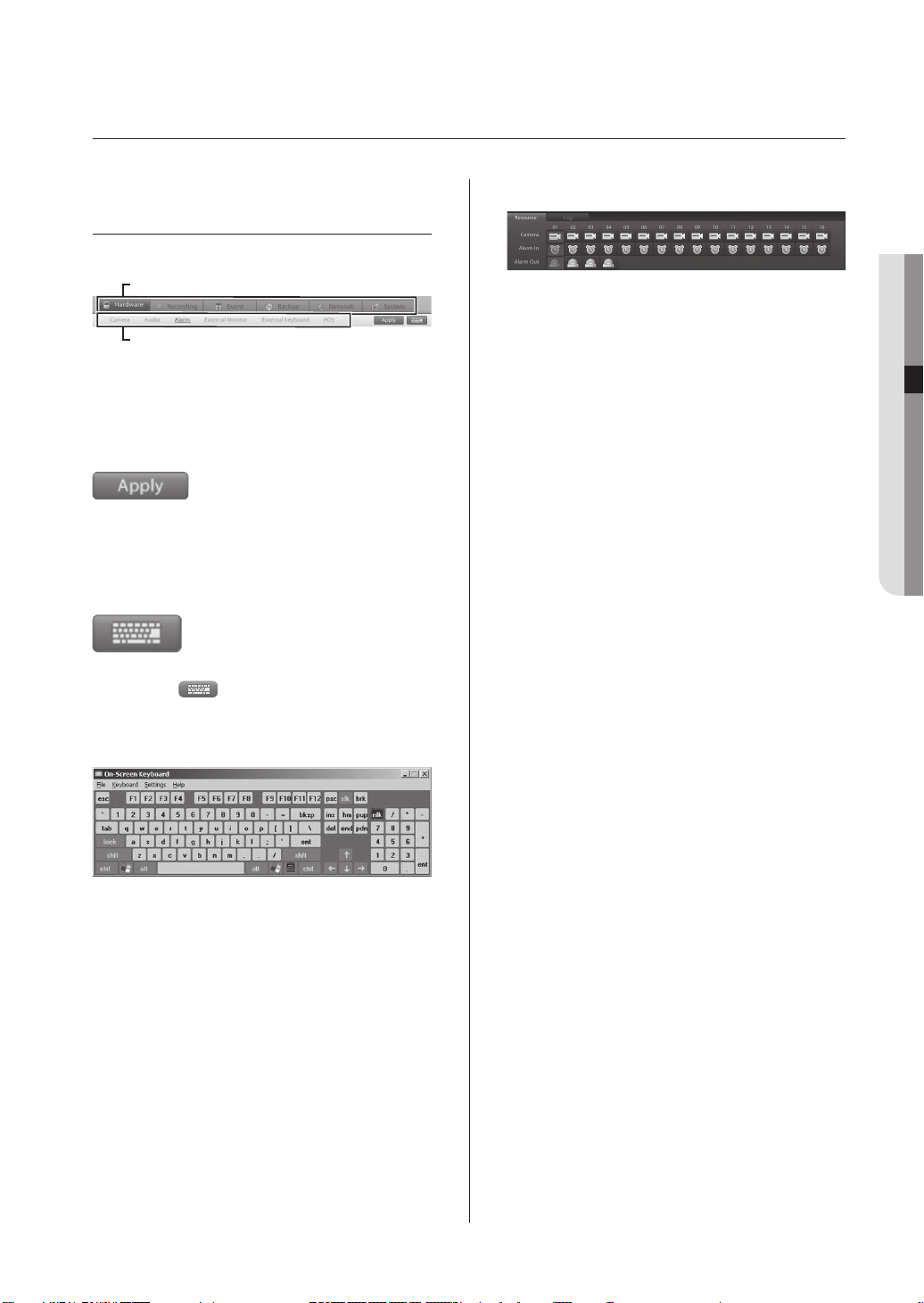
Setup menu category buttons
Main Menu
Sub Menu
Select from individual system setup categories.
The main setup categories are Hardware, Recording,
Event, Backup, Network, and System.
Saving Changes
Apply: Applies any change that has been made in the
Virtual Keyboard
system setup.
Click on the
keyboard.
With the virtual keyboard, key entries can be made
using the mouse.
button to launch the virtual
Camera/Alarm In/Alarm
Camera: Use to select cameras you wish to configure.
Alarm In: Use to select sensors (Alarm In) you wish to
Alarm: Use to select alarms (Alarm Out) you wish to
configure.
configure.
05 SYSTEM SETUP
System Setup _21
Page 26
22_ System Setup
HARDWARE
This category applies to the external devices that form your DVR system. External devices like cameras, audio devices,
sensors, alarms, monitors, keyboards, and POS devices Setup. These options can be used to confi gure a security
system to meet your operating environment.
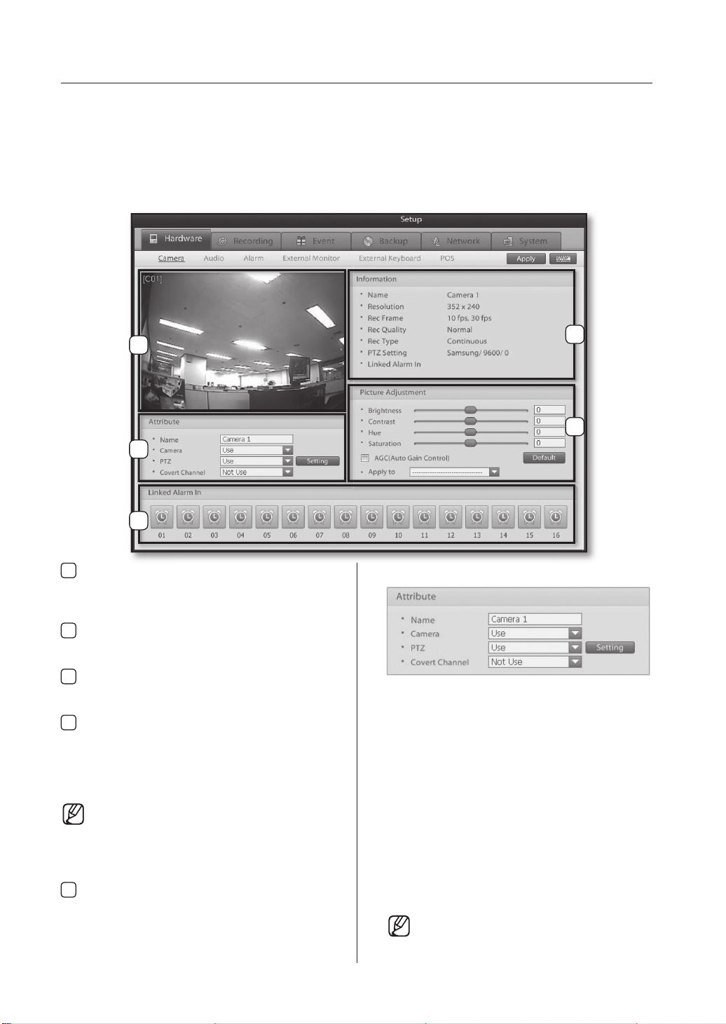
Camera
Use this menu to enable/disable individual cameras and to confi gure the brightness, contrast, hue, and saturation levels
of the video source. In addition, select whether to enable PTZ use and assign covert attributes to video feeds.
1
3
5
Video Display Window
1
Displays the selected camera video feed.
Changes to camera settings can be verifi ed from
this window.
Information
2
Displays information about the selected camera
channel.
Attribute
3
Confi gure the camera name, mode, PTZ setting,
and covert channel.
Picture Adjustment
4
Use this feature to adjust the video signal's brightness,
contrast, hue, and saturation levels. Clicking on the
Default button will return all settings to default. Automatic
Gain Control is a feature that automatically adjusts the
brightness level for the camera.
The screen adjustment functions cannot be
expected to improve the quality on a low
quality video signal. Also make sure that
the camera and monitor have been setup
correctly before making video adjustments.
Linked Alarm In
5
Select which sensor to link with the selected
camera. When an event is detected, the selected
sensor will initialize the camera to commence
video recording.
2
4
Camera Attribute
Name: Enter a name (Suggestion: Camera location).
Camera: Enable or disable the selected camera.
PTZ: Enable or disable PTZ use for the selected
camera.
Setting: Click the setting button to access PTZ
protocol setup and communication
confi guration options.
Covert Channel: Enable or disable Covert Channel
option for the selected camera.
Covert Channel is a feature that
hides the selected camera's video
feed. This feature is particularly
useful when you don’t want selected
users/people to view the camera
feed, recording or location.
When monitoring video feeds from a
remote location, covert video feeds are
viewable by authorized users.
Page 27
05 SYSTEM SETUP
System Setup _23
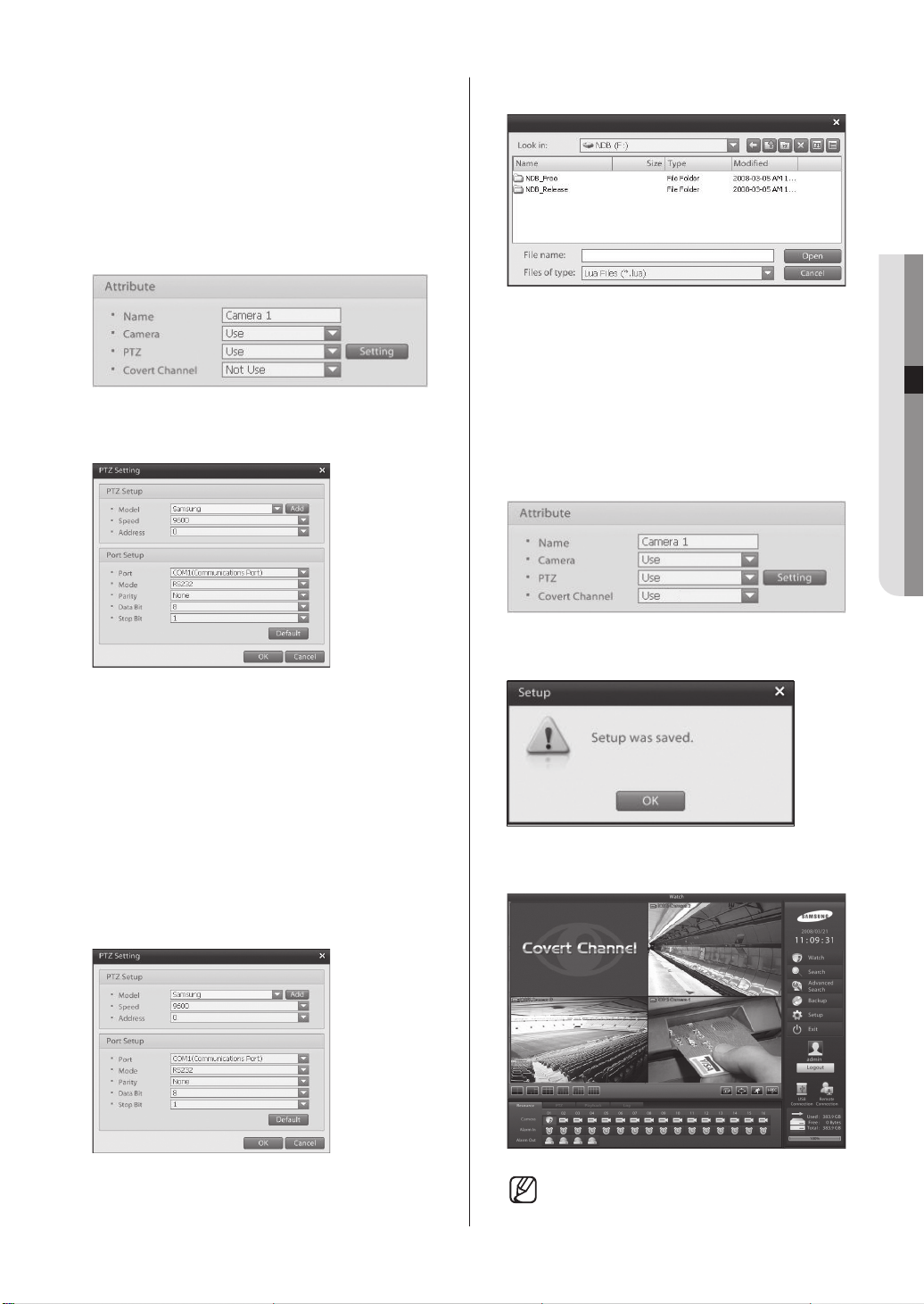
This DVR system allows you to remotely control
PTZs, speed domes, and other external devices
connected to the system. Before using this feature,
however, you must install the external device to
the RS485 port and configure the external device
settings.
PTZ Setup
1. To select a camera for PTZ control set the
PTZ option to Use.
2. Select the PTZ model you wish to add.
2. Click on the
following window:
3.
Define the model, baudrate, address, and
communication method of the PTZ installed
to the DVR.
4. Click on the OK button to finish configuring
the PTZ.
Setting button to access the
3. Click on the
PTZ model.
Open button to register the selected
Covert Channel Setup
1. Select the camera channel you wish to set as a
Covert Channel.
2. Set Covert Channel option to Use.
Click on the Apply button and then, when the
3.
following window prompts, click on the OK button.
Add to PTZ List
1. To add a new PTZ model, click on the Add button:
4. The covert channel sign will be shown instead of a
video feed on the display screen.
The video feeds will be shown when logged in
as a user with secure channel permission.
Page 28
24_ System Setup
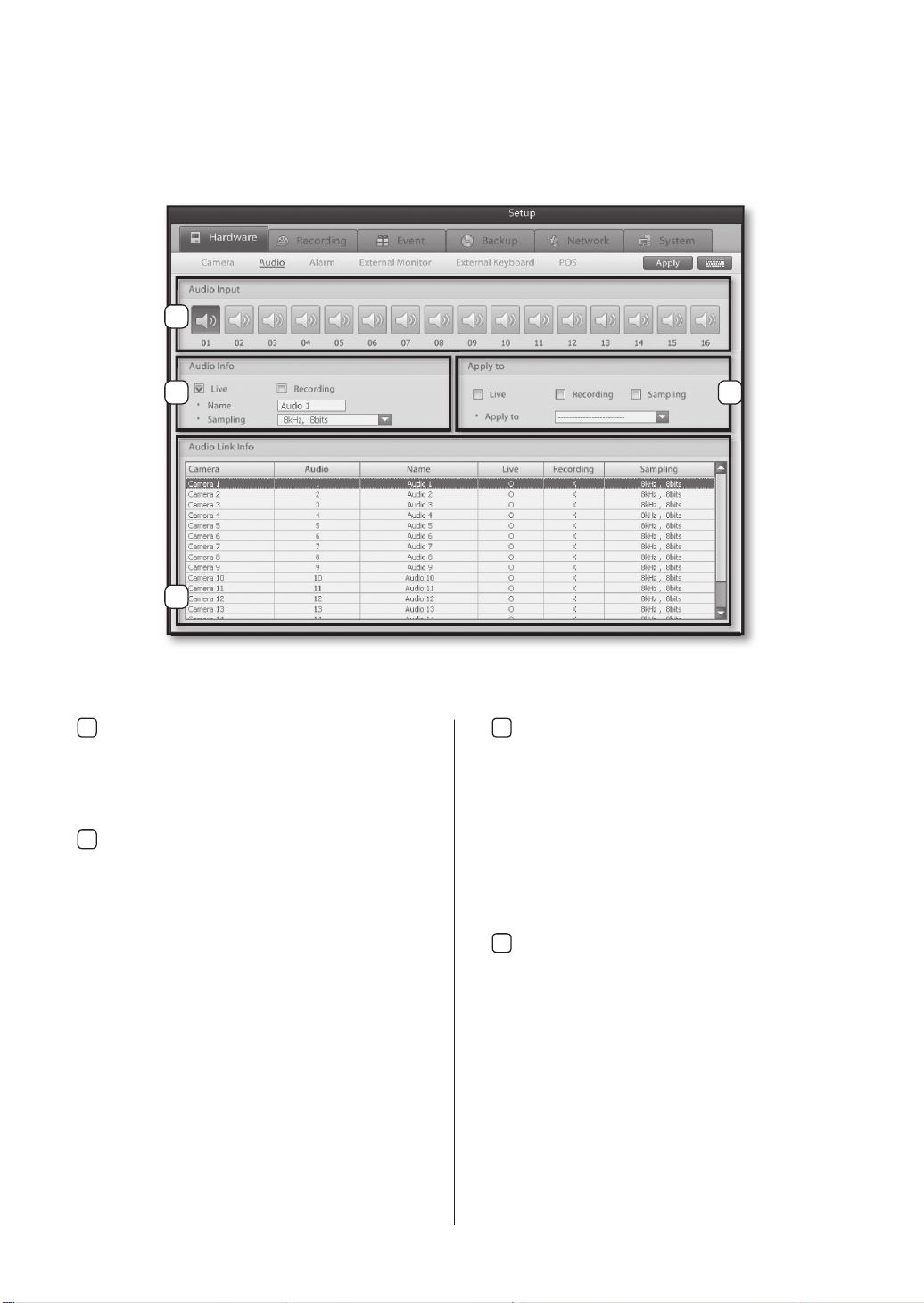
Audio
Use this menu to enable/disable live audio output and audio recording.
1
2
4
Audio Input
1
This menu allows you to associate individual
audio input channels to each camera channel.
Select a camera channel and then the audio input
channel you wish to associate to the selected
camera channel.
Audio Setup
2
Live: Enables/disables live audio output on the live
screen.
Recording: Enables/disables audio recording.
Name: Enter the name of the audio channel.
Sampling: Select the desired recording sampling
rate.
3
Apply to
3
Live: Select this option if you want to apply the
current live option settings to all or selected
camera channels.
Recording: Select this option if you want to apply
Sampling: Select this option if you want to apply
Apply to: Implements the setting changes for the
Audio Link Info
4
the current recording option settings to
all or selected camera channels.
the current sampling settings to all or
selected camera channels.
selected options to all or selected camera
channels.
Displays the audio properties of each camera
channel.
Page 29
05 SYSTEM SETUP
System Setup _25
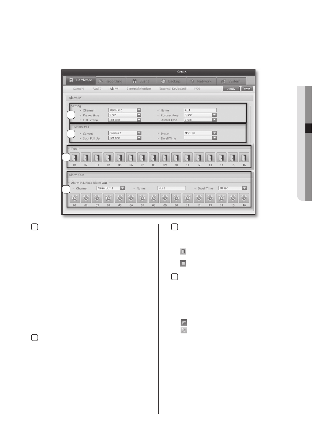
Alarm
This setup category covers sensor, camera, and alarm association settings. By associating a camera to a sensor, you
can confi gure how long the camera is going to record for when a sensor event is detected. In addition, by associating an
alarm output to a sensor, you can setup the alarm output to sound a warning signal when a sensor event is detected.
1
2
3
4
Setting
1
Channel: Select the sensor you wish to confi gure.
Name:Enter the name of the sensor.
Pre rec time: Select the time prior to a sensor event
Post rec time: Select the time after to a sensor
Full Screen: Make the linked camera channels pop-
Dwell Time:
Linked PTZ
2
Camera: Select the PTZ camera channel you wish
Preset: Select the PTZ preset for when the sensor
Spot Full up: Select the camera channel to be
Dwell Time: Set the time that the camera is
that the camera should record.
event that the camera should record.
up full screen on the display screen
when a sensor event occurs.
This option is used to defi ne for how long
subsequent sensor event signals are
ignored after an initial event signal. Enabling
this option instructs the system to ignore
all other event signals transmitted by the
sensor for the set amount of time following
the initial event signal. So once an event
signal is transmitted, the set discard time
must lapse before another event signal can
be recognized.
to associate to the sensor.
event is detected.
displayed full screen on the spot
monitor in a sensor alarm event.
displayed on the spot monitor.
Type
3
Select the input type of the sensor.
Click the button to switch between the NC and
NO option.
: Normally open, but closes when an event is
detected (Normally Open).
: Normally closed, but opens when an event is
detected (Normally Close).
Alarm Out
4
Channel: Select an alarm (Alarm Out) to associate
Name: Enter the name of the alarm.
Dwell Time: Set how many seconds the alarm will
Alarm Out Button: Select a sensor channel to
to the sensor (Alarm In).
be active on a sensor event.
associate to the alarm.
: Indicates an associated sensor.
: Indicates a non-associated sensor.
Page 30
26_ System Setup
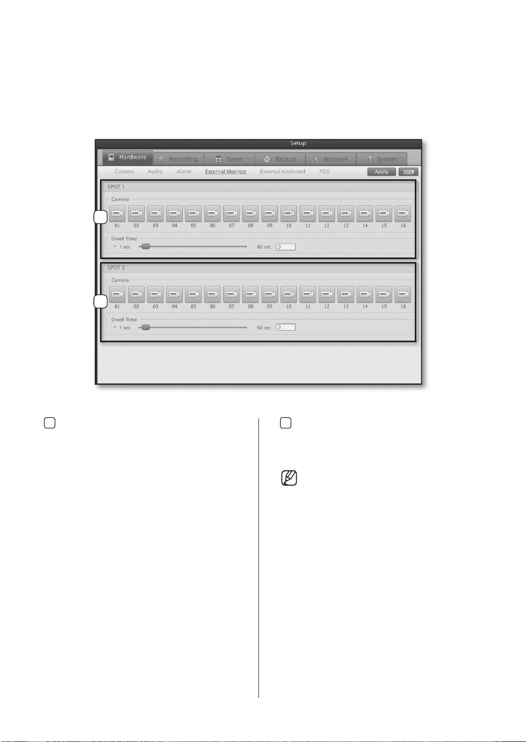
External Monitor
This menu directs video feeds to an external monitor via the spot port. Select the cameras to be display on the spot and
confi gure their dwell time.
1
2
SPOT 1
1
Camera: Select camera feeds to be transmitted by
Dwell Time: Drag the slider left or right to set the
spot port 1.
delay interval between screen changes.
SPOT 2
2
Camera: Select camera feeds to be transmitted by
Dwell Time: Drag the slider left or right to set the
spot port 2.
delay interval between screen changes.
Channels confi gured as a Covert Channel
cannot be displayed on the spot monitor.
Page 31

05 SYSTEM SETUP
System Setup _27
External Keypad
Menu for setting up a keypad device to remotely control the DVR.
1
2
3
DVR ID
1
Enter the DVR's ID (1 through 255) so that the
keypad device may identify the DVR.
Keypad ID
2
Enter the keypad's ID (1 through 4) so that the
DVR may identify the keypad.
Keypad Setup
3
Keypad Name: Assign name to the keypad.
Use: Enable or disable keypad use.
Keypad Model: Select the model of the keypad
Speed: Select a baudrate (2400Bps - 115200Bps)
Address: Select the keypad device’s address (0
Port: Identify the number of the port through which
the keypad device connects to the DVR.
device you wish to use.
for communication between the keypad
device and the DVR.
through 32).
Mode: Identify the interface method (RS232,
RS422, or RS485) of the port through which
the keypad device connects to the DVR.
Parity: Select the bit type (None, Odd, Even, Display,
Blank) for detecting data transmission errors.
Data Bits: Select from 4, 5, 6, 7, and 8.
Stop Bits: Select from 1, 1.5, and 2.
Default: Reset all settings to default.
When using a keypad device, please ensure
that communication settings for both the
DVR and the keypad device are the same.
Communication setting mismatch can
prevent the keypad device and the DVR
from communicating.
Refer to the keypad manufacturer’s
product manual for further information on
the keypad device.
Page 32

28_ System Setup
POS
MENU FOR LINKING THE DVR SYSTEM TO POS DEVICES AND LINKING THE VIDEO RECORDINGS WITH TRANSACTION
RECORDS GENERATED AT POINTS OF SALE.
2
1
3
4
5
6
List
1
Displays the currently confi gured POS device,
with entry add and, update, delete options.
Add: Use to add a POS device to the list.
Update: Use to update the information of a
Del: Use to delete a POS devices information from
POS Settings
2
Name: Enter an appropriate name for the POS
POS ID: Select the ID of the POS device connected
Linked Camera: Select the camera channel with
POS Format: Select the type of POS device or the
Port Setup
3
registered POS device.
the list.
Device.
to the DVR (1 through 16).
the video feed you wish to store
along with POS data received from
the POS device.
text inserter.
Confi gure the settings to allow communication
between POS device and DVR.
Port: Select which DVR port the POS device is
connected.
Mode: Select which interfacing type that the POS is
using.
Speed: Select a baudrate (2400Bps - 115200Bps)
for communication between the POS device
and the DVR.
Parity: Select the bit type (None, Odd, or Even) for
detecting data transmission errors.
Data Bits: Select from 4, 5, 6, 7, and 8.
Stop Bits: Select from 1, 1.5, and 2.
OSD
4
Display OSD: Enable or disable live screen display
of product information transmitted
Display Time: Designate how many seconds you
Display Cam: Select the camera channel on which
Transaction Wait
5
Wait Time:
Select HDD for POS Database
6
through the POS device.
wish OSD data to be displayed on
the DVR’s live screen after product
barcode gets scanned. If new
product information is received, the
information on the DVR screen will
update itself.
to display the information received
from the POS device.
Confi gure how many minutes to wait
until the next product information can
be entered when the barcode reader
temporarily stops working while scanning
a product. While in standby mode,
information of the previous product will be
automatically deleted if no new product
information is entered or the barcode scan
termination button is not pressed.
Select on the system which HDD will be used to
store the POS data.
POS Database: The POS database must be
keep separate from the DVR
system drives. Do not use the
operating system or recording
database HDD to store the POS
data.
Page 33

05 SYSTEM SETUP
System Setup _29
RECORDING
Recording
USE THIS MENU TO ASSIGN DIFFERENT RECORDING SCHEDULES FOR INDIVIDUAL CAMERAS DURING
WEEKDAY, SATURDAY, AND HOLIDAY CATEGORIES.
1 2
3 4 5 6 7
Type
1
You can register and manage up to fi ve different
recording profi les (Options include: Recording
times, Picture quality, Resolution, Emergency
recording time, etc.). In addition, you can assign
different colors to each schedule type for easier
identifi cation.
Timeline
2
Assign the recording type for each timeframe under weekday, Saturday, and holiday categories.
To confi gure the range of the recording method,
select and drag the desired time using your
mouse.
Frame
3
Set the recording fps for each camera.
Quality
4
Set the recording quality for each camera.
Resolution
5
Set the recording resolution size.
Emergency Recording
6
Set the fps (recording frame rate) for when an
emergency event occurs. (To setup the emergency defi nition refer to P.34 - Emergency.)
Apply to
7
The selected channel setting value can be applied
to all or selected channel.
Page 34

30_ System Setup
Schedule
Your DVR gives you fl exibility over recording schedules by allowing you to defi ne and schedule of each individual
camera's recording modes for weekday, Saturday, and holiday timeframes.
This menu displays the recording schedule for the next six months from the current month in calendar
format.
1
2
5
3
4
6
Calendar
1
The calendar consists of six months.
Click on a date to view the camera recording
modes set for that date.
Schedule Mode
2
This feature is used to apply a recording schedule
by weekdays, Saturdays, or holidays.
Weekday: Displays the recording schedule for all
Saturday: Displays the recording schedule for all
Holiday: Displays the recording schedule for all
Recording Mode
3
weekdays.
Saturdays.
holidays.
Displays different types of recording modes.
To apply a recording mode to the recording
schedule, simply select the recording mode then
drag and drop on the timeline.
Continuous: A recording mode that will continuous
Motion: A recording mode that initiates recording
Object Watch: A recording mode that initiates
Alarm In: A recording mode that initiates recording
Pre Rec: A recording mode that records for a
record regardless of event occurrence.
when motion is detected within the camera’
s fi eld of vision.
recording when an object either
appears or disappears from the
camera’s fi eld of vision.
on a sensor event. (Alarm In).
confi gured amount of time leading up to
an event (sensor or motion). This feature is
used to determine the events leading up to
a sensor or motion event.
POS: A recording mode that initiates recording by
POS when a transaction takes place.
Recording mode button states
When dragging the timeline with the mouse,
there are three types of recording mode
button states.
Selected State
Cleared State
Selected and Cleared State
Selected State: 1 When the concerned
recording mode is enabled.
Cleared State: 2 When the concerned
recording mode is disabled.
Selected and Cleared State: 1 When
two different recording modes have been
enabled. 2 Restore to previous setting.
Holidays
4
Use to access a the calendar and confi gure userdefi ned days as holidays.
Timeline
5
Displays the recording mode for each camera on
the selected date. To apply a different recording
mode to a the recording schedule, simply drag
the timeline with your mouse and select the
recording mode.
Apply to
6
Highlight a single channel recording time line then
it can be applied to all or selected channels.
Page 35

05 SYSTEM SETUP
System Setup _31
Holiday Setup
Click on the Holiday button to defi ne holidays.
1
2
5 6 7
Calendar
1
Select a date to defi ne as a holiday.
Cycle
2
Confi gure a repetition schedule for the holiday.
No Cycle: Set no cycle on the selected date.
Every day: Repeat from the selected date for the
Every Week: Repeat from the selected date for the
Every Month: Repeat from the selected date for the
Every Year: Repeat from the selected date for the
List
3
entered number of days.
entered number of weeks.
entered number of months.
entered number of years.
Displays a list of dates designated as a holiday.
3
4
Range
4
Use to defi ne a range for a holiday.
Start: Select the date for the holiday.
Unlimited: Select if you do not wish to designate an
Count Times: Designates the number of times the
End: Designates all days between the start and end
Add
5
unlimited range.
holiday will occur.
date as holidays.
Adds a holiday to the current confi guration.
Update
6
Updates the settings of an entry selected from
the list.
Del
7
Removes the selected entry from the holiday list.
Page 36

32_ System Setup
EVENT
Motion Detection
These settings are used to commence recording when motion is detected within a user-defi ned zone. You can optimize
the recording environment by associating PTZ devices, alarms, and cameras to motion detection events.
2
1
3
5
4
7
6
8
Video Display Window
1
This window is used to defi ne the motion detection zone for the selected video feed. Select the
desired motion detection zone by dragging your
mouse over the screen.
Set Motion Detection Zone:
Left-click on or drag over the desired motion
detection zone with your mouse. The motion
selected areas are highlighted by a green color.
Deactivate Motion Detection Zone:
Right-click on or drag over the motion detection
zone you wish to deactivate.
Zone setting
2
Block Count: Use to designated the number of
Sensitivity: Use to select the sensitivity of motion
Set All Area: Selects the whole screen for motion
Erase All Area: Clears the screen of any motion
3
Rec time
Pre rec time: Use to confi gure how long to record
Post rec time: Use to confi gure how long to record
blocks in the motion detection zone
grid.
detection.
detection.
blocks.
for leading up to a motion detection
event.
for following a motion detection
event.
9
4
Action Setting
Full Screen: Enable or disable full screen display
Beep: Enable or disable the buzzer for events.
5
Linked PTZ:
Camera: Use to associate a PTZ to the motion
Preset: Use to select the desired PTZ preset.
Spot Full Up
6
of video feed when a motion event
occurs.
detection camera channel. When a motion
detection event takes place, this feature
moves the selected PTZ to a preset
position.
Enable or disable full screen spot monitor pop up
of the video feed when a motion event occurs.
Dwell Time: Use to confi gure the duration for
Linked Camera
7
displaying the camera on the spot port.
Link other cameras to record when the selected
camera detects motion. Multiple cameras can be
selected to be linked via motion.
8
Apply to
The selected channel setting value can be applied
to all or selected channels.
9
Linked Alarm Out
Link Alarm Outs to trigger on motion detection in
camera, multiple alarms can be linked via motion.
Page 37

05 SYSTEM SETUP
System Setup _33
Object Watch
Object Watch is a feature that monitors changes in objects by comparing the current video feed segment with a
previous video feed segment. When a change is detected within a set monitoring duration this triggers as an event and
the DVR will commence recording. This feature can be confi gured so that an event triggers recording on associated
cameras, alarm outputs, spot monitor output, etc.
1
2
4
3
5
8
Video Display Window
1
This window is used to defi ne the object watch
zone for the selected video feed.
Set Object Watch Zone:
Left-click on or drag over the desired detection zone
with your mouse.
Deactivate Object Watch Zone:
Right-click on or drag over the detection zone you
wish to deactivate
Object Detection Settings
2
Reference Picture: Displays the reference picture.
Current Picture: Displays the current picture.
Set Reference Picture:
Designates the current video as the reference
picture.
Set Minimum Hold Time:
Used to defi ne the minimum monitoring duration.
An object watch event is generated only if an object
change lasts for longer than the minimum monitoring
duration.
Block Count: Use to designated the number of
Sensitivity: Use to select the sensitivity of object
Set All Area: Selects the whole screen for object
Erase All Area: Clears the screen of any object
Action Settings
3
Full Screen: Enable or disable full screen display of
Beep: Enable or disable the buzzer for events.
blocks for object detection.
detection.
detection.
detection blocks.
video feed upon an object watch event.
6
7
9
4
Rec Time
Pre rec time: Use to confi gure how long to record
Post rec time: Use to confi gure how long to record
5
Spot Full Up
for leading up to a detection event.
for following a detection event.
Enable or disable full screen spot monitor pop up
of the video feed when a object event occurs.
Dwell Time: Use to confi gure the duration for
6
Linked PTZ
Camera: Use to associate a PTZ to a object watch
Preset: Use to select the desired PTZ preset.
7
Linked Camera
displaying the camera on the spot port.
event. When an event takes place, this
feature moves the selected PTZ to a
preset position.
Link other cameras to record when the selected
camera detects an object event. Multiple cameras
can be linked via object watch.
8
Apply to
The selected channel setting value can be applied
to all or selected channels.
9
Linked Alarm Out
Link Alarm Outs to trigger on object detection multiple alarms can be linked via object.
Page 38

34_ System Setup
Emergency
Use this menu to confi gure settings for Emergency. Use this menu to defi ne an emergency in the DVR, emergency can
be used to increase fps, stream video or send E-mail to a remote client.
1
2
3
Motion
1
Select which camera channels to set as emergency for when a motion event occurs.
Video Loss
2
Select which camera channels to set as emergency for when a video loss event occurs.
Alarm In
3
Select which alarm in channels to set as emergency for when a alarm in event occurs.
Page 39

05 SYSTEM SETUP
System Setup _35
Video Loss
Use this menu to confi gure settings for a video loss event. Video loss events can be used to record selected cameras,
move a PTZ camera or trigger an Alarm output.
1 2
3
4
5
Camera
1
Displays the selected camera channel’s designation.
Use Beep
2
Use to enable or disable the buzzer upon video
loss detection.
Linked Camera
3
Select the cameras you wish to associate to the
video loss camera. Video loss detection from
the selected camera initiates recording in all the
cameras associated to that camera, regardless of
their normal recording schedule.
Linked PTZ
4
Camera: Select the PTZ you wish to associate to
Preset: Select the desired PTZ preset channel.
Linked Alarm Out
5
Settings for triggering alarms in the event of a
video loss. Select the desired alarms to associate
to the video loss camera.
the video loss camera.
Video loss detection directs the selected
PTZ to the preset position.
Page 40

36_ System Setup
E-Mail
This feature sends out an e-mail to the administrator when an emergency or system event occurs to facilitate a fast
response.
1
6
E-Mail Address Manage
1
A feature that enables you to organize and manage email addresses into groups. Clicking on the
Mail Group/User Manage button prompts the
E-mail Address Management window.
Name
2
Enter the name of the mailing list you wish to add.
E-Mail Setup
3
Receiver: Enter the recipient’s e-mail addresses.
CC: Enter the email address of Cc recipients.
Subject: Enter the subject of the e-mail.
E-Mail Server Setup
4
Enter the sender’s email address and mail server
details.
Sender Name: Enter the name of the sender.
Mail Address: Enter the sender’s e-mail address.
Server(SMTP): Enter the address of the mail
Server Authorization: Used when security
ID: Enter the email account ID for the mail server
(SMTP).
Password: Enter the e-mail account’s password.
sending server.
password authentication is
required to access the e-mail
account.
2
3
4
5
Condition Setting
5
Select from Emergency Message and Event.
Emergency: Select to use the default emergency
Event: Select to custom confi gure motion detection,
Motion: Select the channels you wish to send out
Video Loss: Select the channels you wish to send
Alarm In: Select the channels you wish to send out
Mail List
6
Add: Add a mailing list.
Update: Edit an existing mail list.
Del: Remove a mailing list.
setting to send the E-mail
video loss, and sensor channels for sending
e-mail.
an e-mail notifi cation for when a motion
detection event takes place.
out an e-mail notifi cation for when a
video loss is detected.
an e-mail notifi cation for when a sensor
(Alarm In) event takes place.
Page 41

05 SYSTEM SETUP
System Setup _37
E-Mail Address Manage
1 2 4
3
Name
1
Enter the name you wish to search.
Search
2
‘Click on the Search button to commence
search.
User List
3
Displays user names registered in the mail list and
their respective e-mail addresses.
Add: Click on the Add button to add a new user
name and email address.
Del: Click on the Remove button to delete selected
contacts from the list.
Group Name
4
Use the drop down menu to select a group.
Selecting a group will populate the names and
email addresses of users assigned to that group.
5
6
7
Add
5
Click to add the selected contacts from the user
list to the group.
Del
6
Click to remove selected contacts from the group
list.
Group List
7
Displays a list of user names and email addresses
assigned to the selected group.
Add: Click on the Add button to create a new
group.
Del: Click to delete the selected group.
Page 42

38_ System Setup
BACKUP
Schedule
Use this menu to make a backup of recorded video data to the designated backup media based on a defi ned schedule.
Select the backup timeframe, backup intervals, and backup media to confi gure a comprehensive backup schedule.
2
1
3
4
5
List
1
Add: Click on this button to add a backup profi le to
the list.
Edit: Click on this button to edit a backup profi le.
Del: Click on this button to remove a backup profi le.
Backup Title
2
Enter the name of a backup profi le you wish to
add to the backup list.
Time Setting
3
Daily: Select if you wish to backup the defi ned
recording timeframe at the designated time
on a daily basis.
Weekly: Select if you wish to backup the defi ned
Destination
4
Server: Select the server you wish to backup to.
Media: Select the desired backup media.
Device: Shows the device path and type of media.
Path: Select the desired backup folder path.
recording timeframe at the designated time
on a weekly basis.
6
Item
5
Settings for defi ning recording data segment you
wish to backup.
Continuous: Select to backup continuous recording
Motion/Object Watch: Select to backup motion
Alarm: Select to backup sensor detection recording
Event: Select to backup instant recording and video
Pre Rec: Select to backup PreAlarm recording
Audio: Select to backup audio segments of
Camera
6
segments of recorded data.
detection recording
segments of recorded data.
segments of recorded data.
loss recording segments of recorded data.
segments of recorded data.
recorded data.
Select the cameras you wish to backup.
Page 43

05 SYSTEM SETUP
System Setup _39
NETWORK
Network
You can confi gure the network components to enable remote control management and video/audio streaming features
on your DVR.
1
2
3
IP Auto Allocation (DHCP)
1
This option is to allow the DHCP server to automatically allocate a dynamic IP address for your
DVR or to confi gure a manual IP designation. If
set to manual, you will need to manually enter the
IP address, subnet mask, and gateway address.
Auto DNS Server Setting
2
Enter the DNS server’s details to the primary DNS
server and alternate DNS server fi elds.
Remote Connection
3
Bandwidth: Designate the maximum rate of video
Acceptable Count: Designate the number of clients
Web DVR Support: Enable or disable access to the
Viewer Support: Enable or disable Viewer
Port Number: Enter the number of the network port
data streaming over the network.
you wish to allow remote
connection.
DVR for Web DVR connection.
connection.
for main viewer connection. Click on
the Port Check button to fi nd out the
access permission of the entered
network port.
Contact your network administrator or internet
service provider if you are not familiar with your
network environment or do not know the IP
address.
Remote connection and monitoring by a large
number of users can result in a heavy load for
your system and even disrupt basic system
functionalities. This menu is designed for
situations requiring restriction on the number
of user connections and will reject additional
DVR server connections beyond the designated
number.
Your DVR utilizes six ports to provide network
services. If making changes to the ports, you
must be careful to assign redundant port
numbers. The following table shows the network
ports used by the DVR unit:
WebDVR Port 80
Video Transmission and DVR Control Port 12000
Software Upgrade Port 12004
Emergency Video Transmission Port 12005
Two-Way Audio Transmission Port 12006
Two-Way Audio Reception Port 12007
Forwarding of these ports is required for
connecting the DVR through an IP router. For
more information on port forwarding, please
refer to the IP router’s user manual or contact
the router’s manufacturer.
Network Port Port Number
Page 44

40_ System Setup
DDNS
This menu can be used to enable the DDNS (Dynamic Domain Name System) on the DVR system. DDNS is used so
that, you can connect your DVR system to DHCP server and have a fi xed address.
1
2
3
Account
1
ID: Enter the ID of your DDNS server account.
Password: Enter the password for your DDNS
server account.
Network
2
Server Address: Enter the address of the DDNS
Server Port: Enter the port number of the DDNS
Client Port: Enter the port number of DDNS’s client.
Update Time: Enter the interval time for updating
Options
3
Use Samsung DDNS: Select if you wish to use the
Use External DDNS: Select if you wish to use a
server.
server.
the DVR data to the DDNS.
DDNS server administrated
by Samsung Electronics.
DDNS server other than the
one offered by Samsung
Electronics.
If Samsung DDNS (websamsung.net) is
selected, a DDNS address will be automatically
allocated using the physical address of the
ethernet card attached to the main unit. With
an Ethernet card whose MAC address is
00-0c-8c-ab-cd-ef, for example, the domain
gets automatically assigned as aabcdef.
websamsung.net. Here, abcdef designates the
last six digits of the card's MAC address and
the “a” denotes the DVR (mode: SPR-9x16)
identifi cation code.
When confi guring an external DDNS (dyndns.
com, no-ip.com, changeip.com), it takes
approximately 30 to 60 seconds to update the
URL IP to the DNS.
If you are accessing a network directly via an IP
router, you must designate the DDNS network
port under the IP router’s setup menu.
If you are receiving dynamic IP allocation for your DVR
unit using your IP router’s DHCP feature, you must
designate a port for the received IP under the IP router
’s setup menu. For applications using an IP router,
Samsung Electronics recommends that instead
of using the DHCP feature you fi rst designate the
allocated IP and port number under the router’s setup
menu, set the main unit’s connection mode as fi xed
IP, and then directly enter the designated IP on the
IP router. Please refer to your IP router’s user manual
or contact the router manufacturer for instructions on
router confi guration.
Page 45

05 SYSTEM SETUP
System Setup _41
Stream Control
Defi ne frame rate, resolution, and picture quality settings of individual camera channels you wish to stream over the
network.
1 2 3 4
Use
1
Enable/Disable the cameras you wish to stream
over the network.
Remote Frame
2
Adjust the network streaming frame rates for
individual cameras.
Remote Resolution
3
Adjust the streaming resolution setting for individual cameras.
Remote Quality
4
Adjust the streaming picture quality for individual
cameras.
Page 46

42_ System Setup
Emergency Monitor
Use this menu to setup video transfer to the emergency monitor on a remote PC in emergency situations or when an
event is detected. In order to utilize this feature, you must confi gure the address of the remote PC, the port number,
streaming duration, and notifi cation item.
2
3
4
1
5
List
1
Add: Click to add a new emergency monitor setup
to the list.
Edit: Click to edit and update a emergency monitor
setup.
Del: Click to remove the selected emergency
monitor connection info.
Name
2
Enter the name of the emergency monitor setup
you wish to add to the list.
Remote Address
3
Address: Enter the IP address of the emergency
Port: Enter the emergency monitor’s port number.
Emergency Stream Transfer Time
4
monitor-installed remote PC.
(Standard: 12005)
Confi gure how long you wish to stream the video
feed in the event or an emergency of event detection.
Condition Setting
5
Select which notifi cations will transmit video feed
to the remote PC’s emergency monitor.
Emergency: Select to use the DVR preset
Event: Select to custom confi gure motion detection,
Motion: Select the channels you wish to stream
Video Loss: Select the channels you wish to
Alarm In: Select the channels you wish to
emergency setup confi guration.
video loss, and sensor channels.
video feeds to the remote PC’s emergency
monitor when a motion detection event
takes place.
stream video feeds to the remote PC's
emergency monitor when video loss is
detected.
stream video feeds to the remote PC’s
emergency monitor when a sensor (Alarm
In) detection event takes place.
Page 47

05 SYSTEM SETUP
System Setup _43
SYSTEM
User
Use this menu to manage user accounts and groups. By assigning and restricting system access for user and group
accounts, you will be able to implement systematic management of your DVR system in a multi-user environment.
3
1
4
5
6
7
2
Group List
1
Displays a list of registered groups.
Add: Click to add a new group.
Remove: Click to remove the selected group.
User List
2
Displays a list of registered users.
Add: Click to add a new user.
Remove: Click to remove the selected user.
Account
3
Displays details of the DVR access-authorized
users and groups.
Name: Displays the user account identifi cation.
Password: Displays the account’s password using
E-mail: Displays the email address registered to the
Group: Displays the group the user account belongs
Phone: Displays the telephone number registered to
Description: A description on the user account or
Server
4
asterisks.
user account.
to.
the user account.
group.
Gives authority to stop DVR server operation and
to allocate hard drives for image data storage.
Stop: Gives authority to terminate DVR server
operation.
DB Alloc: Gives authority to allocate the hard drives
on the DVR for image data storage.
8
Watch
5
Permission for, 1-channel search, PTZ control,
covert channel monitoring, and instant recording
authorities from the monitoring screen.
Login: Gives authority to log into the watch screen.
Instant Playback: Gives authority to perform
PTZ Control: Gives authority to perform PTZ
Covert Channel Search: Gives authority to monitor
Instant Recording: Gives authority to commence
Search
6
1-channel search from the
monitoring screen.
control.
video feeds confi gured as
covert channels.
instant recording of selected
cameras in emergencies by
clicking on the I-REC button.
Permission for, backup, and hidden channel
authorities from the search screen.
Login: Gives search authority.
Backup: Gives authority to backup video recordings
Covert Channel Search: Gives authority to view
Setup
7
to the storage device.
Covert Channels during
search.
Gives authority to change DVR system operation
settings.
Login: Gives authority to enter the setup menu.
Page 48

44_ System Setup
Camera: Gives authority over camera confi gurations.
Alarm: Gives authority over sensor and alarm
confi gurations.
External Monitor: Gives authority for external
Recording: Gives authority over recording
Schedule: Gives authority over recording schedule
Motion: Gives authority over motion recording
confi gurations.
Emergency: Gives authority over emergency
Video Loss: Gives authority over video loss
E-Mail: Gives authority over event notifi cation email
confi gurations.
Backup: Gives authority over backup confi gurations.
Network: Gives authority over network
DDNS: Gives authority over DDNS confi gurations.
Stream Control: Gives authority over streaming
Setting: Gives watermark, video standard, recording
method, system reboot, and language
confi guration authorities.
Date/Time: Gives authority over system date and
Information: Gives authority to view information
Audio: Gives authority over audio confi gurations.
Emergency Monitor: Gives authority over
POS: Gives authority over POS confi gurations.
Object Watch: Gives authority over object detection
External Keyboard: Gives authority over external
Camera
8
monitor video feed
confi gurations.
confi gurations.
confi gurations.
situation confi gurations.
notifi cations.
confi gurations.
options.
time confi gurations.
on system operating system and
hardware, DVR program, etc.
emergency remote notifi cation
settings.
confi gurations.
keyboard confi gurations.
Assign monitoring and search camera channels
for the user or group.
Admin account has all DVR access rights.
The admin account can create, void, and
access other user accounts.
Non-admin accounts cannot modify their
own access clearance. This can only be done
through the admin account.
Adding a Group
1. To add a new user group, click on the Add button
from the following window:
2. Enter the name and description for the new
group.
3. Click on the OK button to fi nish.
Page 49

05 SYSTEM SETUP
System Setup _45
Deleting a Group
Adding a User Account
1. Select the group you wish to delete.
2. Click on the Delete button.
3. A window will prompt “Are you sure you want to
delete the group?” as shown below. Click on the
Yes button to continue with deletion.
1. To add a new user account, click on the Add
button from the following window:
2. Enter the name, password, group association, and
other information about the user account you wish
to include.
4. The following message will prompt if there are
user accounts assigned to the group you chose
to delete. Clicking on the Yes button will delete all
users in the group. Clicking on the No button will
delete the group only.
5. You can then verify the deletion.
3. Click on the OK button to fi nish adding a new user
account.
Page 50

46_ System Setup
Deleting a User Account
1. Select the account you wish to delete.
2. Click on the Delete button.
3. A window will prompt “Are you sure you want to
delete the user?” as shown below. Click on the
Yes button to continue with deletion.
4. Verify that the user account has been removed
from the list.
Page 51

05 SYSTEM SETUP
System Setup _47
Setting
Use this menu to setup and view the General settings on the DVR. The settings include Audio delete, Watermark, Video
format, Language, Recording type, System restart, System Log, S/W upgrade and a Import and Export function.
1 2
3 4
5 6
7
Auto Delete
1
This feature automatically deletes recording database
data after the designated amount of time lapses.
Use Auto Delete: Check to enable automatic
DB Retention Time: Designate how long you
Watermark
2
database deletion.
wish the database data to be
maintained. Database deletion
term can be confi gured in
units of hours, days, weeks, or
months
This feature embeds watermark encryption into
the recorded video data.
Watermark: Enable or disable embedding of
Display: Enable or disable watermark certifi cation
Watermark embeds a watermark that is invisible
to the naked eye but recognizable by Samsung
Electronics. If someone were to forge or alter the
video recordings, you can use the watermark to
authenticate the data.
Video Format
3
watermark on video recordings.
display on video recording playback.
Select the video format of the cameras. You can
choose between NTSC and PAL. Once you've
selected a format method, the system will restart.
Language
4
Your DVR system supports multiple languages.
From this menu, you can confi gure the system to
a desired language.
Recording Type
5
Once recording and Cycle (overwrite) recording
are the available recording options.
Choosing single recording will suspend all additional recording once the hard drive space has
been completely fi lled up. Setting to repeated recording, on the other hand, will overwrite starting
from the oldest data once the hard drive space
has been completely fi lled up.
System Restart
6
This feature automatically restarts the system
at designated times to ensure greater system
stability. Restarting the DVR can minimize system
errors and increase the overall system stability.
Use: Enable or disable the system restart feature.
Day: Select a date for system restart.
Time: Select a time for system restart.
Etc
7
Log Information: This feature records all DVR
S/W Upgrade: Use this feature to upgrade your
Import/Export: Use to backup the setup profi le of
system operational processes.
The log feature allows you to
easily identify and correct system
issues.
DVR software.
the system to a storage device or to
import a setup profi le from a storage
device to the system.
Page 52

48_ System Setup
Log information
The log menu records all DVR system operation processes.
1 2
3 4
5
9
Options
1
Log Path: Displays the fi le path for storing the log
Duration: Enter the amount of time you wish to
Item
2
System: Select to store the system information log.
Network: Select to store the network information
Video:
DB:
Setup: Select to store If confi guration data has
Backup: Select to store the backup information log.
Alarm In:
Alarm Out: Select to store the alarm (alarm-out)
Notifi cation: Select to store the emergency
Date/Time Filter
3
fi le. Click on the Browse button and
select the path you wish to store the log
fi le.
store the log fi le. Your system will maintain
the log fi le for the duration you specify.
Any data older that the duration will be
deleted from the system.
log.
Select to store the video loss and video input log.
Select to store the database information log.
changed.
Select to store the sensor (alarm-in) event log.
event log.
status and other externally-sourced
information log.
This feature fi lters out the log data using defi ned
parameters.
Range: Select the desired range of dates for log
data search.
Start: Select the starting date and time for log data
search.
End: Select the ending date and time for log data
search.
76
Search: Click on the Search button to commence
log data search using the defi ned start/end
date and time parameters.
Categorization Filter
4
8
Extracts and displays log data that meets designated level and type conditions.
Level: Select the desired log list level.
Type: Select the desired log item type.
View Count
5
Select the maximum number of lines to be
displayed on the log list. Log entries beyond the
selected number are carried over to the next
page.
Page Control
6
Use to fl ip through the log list pages.
First Page
Next Page
Print
7
Current Page/
Total
Next Page
Last Page
Prints the log data.
Save as...
8
Copies the log data to a different media.
Log List
9
Displays the search results for the log.
Go
Page 53

05 SYSTEM SETUP
System Setup _49
Upgrading Software
1. Click on the Software Upgrade button to upgrade
the system software.
2. From the following window, select the software
upgrade package fi le (.zip format).
3. Click on the Open button to start the software
upgrade.
Import/Export
1
3
4 5
Path
1
Displays the location for exporting/importing the
system profi le.
Path Button
2
Select the location for exporting/importing the
system profi le.
System Profi le List
3
Displays system confi guration components.
Select the desired system confi guration component and commence the import or export
process.
Import
4
Imports a system profi le fi le onto the system from
an external storage device.
Export
5
Exports the current system profi le fi le to an external storage device.
2
4. Once the software upgrade has completed, the
DVR application will restart.
Page 54

50_ System Setup
Date/Time
Confi gure the current date and time for your DVR system. Select the time zone for your current location and if you
desire to set the time by synchronizing with a NTP (Network time protocol) server.
1
2
3
4
Date/Time Setup
1
Use to designate a time zone for the DVR system and set the Current date and time.
Date/Time: Use to update the system’s time and
Time Zone: Select the time zone for your area.
Date Format: Select the date format that you wish
Delimiter: Select a character to use for separating
Time Server
2
date settings. Click on the Get internet
time button to acquire the current time
from the NTP server. Clicking on the
Update button applies newly confi gured
time as the system’s current time.
Click on the Update button to apply the
selected time zone to the system.
to use.
the day, month and year
Enter the address of the NTP server you wish
to synchronize with the DVR.
Click on the Add
button to register additional NTP servers. Click on
the Remove button to remove a registered NTP
server addresses.
Automatic Time Synchronization Settings
3
This feature automatically synchronizes your
system’s time with the NTP server.
Automatic Time Sync at Boot-up:
Synchronizes the system’s time with the NTP server
every time the system restarts.
Schedule time setting: Synchronizes the system's
Overwrite Option
4
time with the NTP server at
scheduled intervals.
When a Newly confi gured time is earlier than
the present system time, this option is used to
decide whether or not to delete data recorded
between those two times. The fi rst option will
overwrite the data recorded between those
two times and updates the system time with
the new confi guration. The second option
does not overwrite data recorded previous to
the orignal time. The recording will commence
again once the system time has realigned with
the original system time.
Page 55

05 SYSTEM SETUP
System Setup _51
System
This menu displays the information about the DVR system and Hardware.
1 2
System
1
This displays the DVR system operating system.
processor type, memory, graphic card, LAN card
and HDD information.
System Info
2
This displays the DVR systems name, location,
software version, model, administrator name and
A/S Diary.
Page 56

52_ Search
Search
SEARCH SCREEN
Search mode enables you to search video recordings, audio data, and events. In addition, the mode offers multiplecamera search and various image ratio and zoom-in/zoom-out features. Also you can bookmark or make a screen
capture of still images and export a backup recording to DVD RW or USB storage devices.
2
1
3 4
5
6 7 9
Video Display Window
1
Video playback is shown in this area.
Time Display
2
Displays the current time.
Split Buttons
3
These buttons indicate 4-, 6-, 9-, 10-, 13-, and
16-split screen modes.
Search Date
4
Select the desired search date and time.
Camera Button
5
Select the cameras you wish to search.
Timeline
6
Displays recording data for each camera channel.
Playback Control
7
Select to playback video data in forward and
reverse modes. Control the playback speed and
adjust the volume level for audio data.
Adj./Event/Info
8
Adj.: These controls are used to adjust the
brightness, contrast, sharpness level and zoom
controls on the video data.
Event:
Displays the event list. Selecting an event on the
list will launch the playback of the selected event.
Info: Displays recording period and the total number
of days recorded.
13
8
10 11 12
Calendar
9
Indicates days on which recording data exists.
Selecting a date that contains recording data
enables you to search recordings on that date.
Snapshot
10
This feature takes still images from the video display window and saves them as a JPEG or BMP
fi le.
Printer
11
Prints the current video image displayed.
Refresh
12
Refreshes the timeline with the most recent
recording data.
Menu Buttons
13
Watch: Accesses the Live Watch screen.
Search: Exit from the Search screen.
Advanced Search: Accesses the Advanced Search
Backup:
Setup: Accesses the System Setup screen.
Exit: Use to terminate the DVR program or the
Accesses the Backup confi guration screen.
system.
screen
Page 57

Search _53
06 SEARCH
SEARCH DATE AND TIME
SELECTION
Use the calendar to move between days, months and
years. Selecting a date that contains recording data
enables you to search recordings for that day.
Selecting Search Date And Time
1. From the calendar, select the date you wish to
search.
2. Move the timeline bar left and right to select the
timeframe you wish to search.
Yellow Video Loss
Purple Instant Recording
Timeline Bar
4
Move the timeline bar left and right to select the
desired search time.
Scroll
5
Move the scroll bar up or down to view additional
camera channels that aren't currently displayed. .
It’s possible to change the scale of the timeline. Leftclick on the time scale to select up to fi ve levels of
zoom. This feature can be used when precise control
in a smaller interval is needed.
Timeline Zoom-In
1. Left-click on the time scale.
2. You will zoom-in closer with each left-click of the
mouse.
Timeline Bar
TIMELINE
1
2
3
Sel All Cam
1
Use to select or deselect all cameras.
Camera
2
Use to manually select individual cameras.
Recording Timeline
3
Provides color-coded graphical display of
recording durations and modes.
Orange Continuous Recording
Blue Motion Recording
Grey
Green Alarm In Recording
Yellowish Green PreAlarm Recording
Dark Blue POS Recording
Object Watch Recording
4
Timeline Zoom-Out
1. Right-click on the time scale.
5
2. You will zoom-out farther away with each right-click
of the mouse.
Page 58

54_ Search
SEARCH SCREEN PLAYBACK
SCREEN ADJUSTMENT
Playback
Select the camera channel and date for playback.
Then, click on the play button to start playback of the
recording.
First recorded Data
Single Frame Reverse
Reverse Playback
Forward Play
Stop
Single frame forward
Last recorded Data
Normal FastSlow
Maximum
Speed
Mute
High Volume
Picture Quality Adjustment
1. From the search screen, select the camera channel
you wish to adjust.
2. Click on the Adjust tab to access
adjustment controls.
1
2
3
picture
SPLIT-SCREEN SETUP
You can select a split-screen mode for search screen
playback.
4-
6
-
9
-
10
-
13
-
16
Screen
Screen
Screen
Screen
Screen
-
Screen
4 5 6 7 8
BR
1
Use to adjust the brightness level of the video
image.
CO
2
Use to adjust the contrast level of the video image.
SH
3
Use to adjust the sharpness level of the video
image.
Zoom-In
4
Use to zoom-in on specific sections of the video
image.
Zoom-Out
5
Use to zoom-out from specific sections of the
video image.
Move
6
Use to move about the video recording after
zooming-in on a specific section.
Reset
7
Resets video recording picture quality settings
back to default.
Expand Screen
8
Use to expand or shrink the video recording.
Page 59

Search _55
06 SEARCH
3. Adjust the brightness, contrast, and sharpness
levels by using the BR, CO, and SH slide bars.
4. To restore picture quality settings to default, click
on the button.
Expanding/Shrinking the Screen
1. From the search screen, select the channel you
wish to expand or shrink.
Video Zoom-In
1. Playback the recording period of interest.
2. From the search screen, select the channel you
wish to zoom-in.
3. Click on the
then turn into .
4. Place the mouse pointer over the section you wish
to zoom-in.
5. Left-click on the mouse to zoom-in on that section.
button. The mouse pointer will
2. Click on the
screen.
button to expand or shrink the
6. To deactivate the zoom-in feature, click on the
button once more.
Page 60

56_ Search
Video Zoom-Out
Video Move
1. From the search screen, select the channel you
wish to zoom-out.
2. Click on the button. The mouse pointer will
then turn into .
3. Place the mouse pointer over the section you wish
to zoom-out.
4. Left-click on the mouse to zoom-out from that
section.
1. Zoom-in on the video.
2. Click on the button. The mouse pointer will
then turn into .
3. Click on the video section you wish to move and
drag.
5. To deactivate the zoom-out feature, click on the
button once more.
4. To deactivate the move feature, click on the
button once more.
Page 61

Search _57
06 SEARCH
EVENT SEARCH
PRINTING
This feature displays events that have happened on
the DVR system. All events, including motion and
sensor detection events, get populated on an the
event list. By double-clicking on a particular event
from the list, you can playback the video recording
associated to that event.
Searching Events
1. Click on the Event tab to start events search.
Previous Page
Camera
Channel
Selection
Events List
2. From the event list, double-click on the event you
wish to search.
Current Page
Next Page
Printing Search Screen
1. Select the search screen you wish to print.
2. Click on the button and the following window
will be displayed. Then select a printer.
3. The video recording associated to the selected
event will be displayed on the search screen.
3. Click on the button to start printing.
The following error message will prompt if your printer
has not been confi gured properly:
Printer Configuration
1. Click Start Settings Printers
2. In this
window, double-click on Add Printer.
3. When Add Printer Wizard starts, click Next.
4. If your printer is connected to the PC, select the
local printer option and then click Next.
5.
When prompted for the make and model of your
printer, either click on the Have Disk... button or
select an appropriate driver for your printer.
6. Follow the instructions on screen to install the
driver and finish configuring your printer.
Print Size
1. By default, images are printed the same size
that they are displayed on the screen.
Printing Failed
1. Verify that your printer has been configured
properly in Windows.
2. If the printer has been properly configured but
the problem persists, check that the printers
printer and power cables are connected
properly.
.
Page 62

58_ advanced search
advanced search
EVENT SEARCH
Event Search is a feature that searches and displays only the video recordings created by motion detection, sensor
detection, alarm, object detection, and video loss events.
1
4
2
3
Video Display Window
1
Searched video recordings are shown in this area
Options:
2
Event: Select the type of events you wish to search.
Continued Search: Set the amount of events to
Start & End: Use to defi ne the search timeframe.
Search
3
Click to start the search process.
show for each search. Tick
the continued search box to
make search continue from the
last time entry of a preceding
search.
This timeframe can be confi gured by
right clicking the timeline and dragging
or enter manually into the boxes.
Event List
4
Search results are displayed in this section. Selecting an event from the list launches the video
recording associated to that event.
Alarm In Sensor signal detection
recording event
Object Watch Object detection recording
event
Motion Motion detection recording
event
Video Loss Video loss recording event
Instant Recording I-REC button-initiated recording
event
POS POS transaction-initiated
recording event
Pre Rec Pre Rec (Motion or Alarm In)
recording event
Page 63

advanced search _59
07 ADVANCED SEARCH
SEQUENTIAL SEARCH
Sequential Search is a feature that displays video recordings from a selected channel in a chronological sequence.
1
2
4
3
Video Display Window
1
Initiating Sequential Search creates a continuing
series of video images from the selected camera
channel under a selected split-screen mode.
Split Buttons
2
Use to select the desired split-screen mode for
the Sequential Search.
Camera Buttons
3
Used to designate which channel to use for
Sequential Search.
Playback Panel
4
Used as the play button to initiate Sequential
Search.
Page 64

60_ advanced search
THUMBNAIL SEARCH
Thumbnail Search is a feature that divides 24 hours of video recording into selected time units and displays the results as
thumbnails.
1
2
3
Video Display Window
1
Searched video recordings are shown in this
area.
Options
2
Intervals: Use to defi ne the time unit for Thumbnail
Continued Search: Set the amount of thumbnails
Start & End: Used to defi ne the search timeframe.
Search
3
Search. 24 hours of video recording
can be divided into units of 1 hour, 30
minutes, 10 minutes or by a user-defi ned
time period.
to show for each search. Tick
the continued search box to
make search continue from the
last time entry of a preceding
search.
This timeframe can be confi gured by
right-clicking the timeline and dragging
or enter manually into the boxes.
Click the Search button to start the Thumbnail
Search.
4 5
6
7
Thumbnail Time Scale Up
4
Reduces the time interval for the thumbnail
search in the scale, 1hour 30minutes 10
minutes 1 minute.
Thumbnail Time Scale Down
5
Increases the time interval for the thumbnail
search in the scale, 1 minute 10 minutes
30minutes 1hour.
Thumbnail Size
6
Use to increase or decrease the size of thumbnails.
Thumbnail Window
7
The search result is displayed in this section.
Results are displayed as thumbnails.
Page 65

advanced search _61
07 ADVANCED SEARCH
OBJECT SEARCH
This feature is used to search for when objects have appeared and disappeared in a user designated zone.
1
2
4
3
Video Display Window
1
This section is where you defi ne object detection
zones and shows a video image of the selected
camera. To search for changes on a selected
channel. Mark a zone(s) on the grid at the area of
interest.
Options
2
Defi ne the object search timeframe and monitoring zone sensitivity.
Set: Use to designate the search sensitivity.
Area Edit: Use to select the whole screen and clear
Continued Search: Set the amount of thumbnails
Start & End: Use to designate the search timeframe.
the screen or use select block to pick
individual blocks in the grid.
to show for each search. Tick
the continued search box to
make search continue from the
last time entry of a preceding
search.
Search
3
Click the Search button to start the object
Search
Object Detection Window
4
Search results are displayed in this section.
Displays video images in which a change has
been detected inside the object detection zone.
With the search timeframe confi gured as
00:00:00 to 24:00:00, video data analysis may
require a long time to fi nish if the subject data
contains numerous object change events. For
this reason, SEC recommends that you search
in 1-hour timeframe intervals.
Page 66

POS SEARCH
POS Search is a feature that searches video data that has been recorded in sync with transaction records taken from a
point of sale device.
1
2
3
Video Display Window
1
Searched video recordings are shown in this area
Options
2
Date/Time: Use to designate the search timeframe.
Query: Search POS database information using
user-designated parameters.
POS: Select the ID of the POS device connected to
the DVR (1 through to 16).
List Count: Use to defi ne the number of returns
shown in the event list.
4
5
Search
3
Use to search POS transaction records.
Products
4
Displays a list of products transacted at the POS.
Events List
5
Displays a list of POS events.
62_ advanced search
Page 67

Backup
different storage device.
BACKUP
Create a backup of recorded data from the DVR to a different storage device.
1
08 BACKUP
2
3
5
7
Format
1
Use to select a desired backup format. Supported
formats are time designation (Time), video fi les (AVI
and SFX), and still images (BMP and JPEG).
Time Backup
(Time)
AVI Backup This option stores data in .avi format,
SFX Backup
(auto execute
fi le backup)
BMP/JPEG
Backup
Source
2
An internal storage method used for
backing up large amounts of data.
which is playable in Windows Media
Player and other generic media player
applications.
This option backs up data along with an
auto execution video player application.
When backed up in this format, opening
a backup fi le automatically launches a
video player for playback. SFX backup’s
maximum capacity is 4GB.
Use to backup video recording by a single
frame. Supports .bmp and .jpeg formats.
Shows the source of the backup.
Backup Sched
3
Designate start and end times for the backup.
Backup Destination
4
Server: Select a backup destination.
Media: Select a backup device.
Drive: Shows the backup device drive letter.
Path: Select a specifi c backup path.
Camera
5
Select camera channels you wish to backup. In
AVI and SFX backup formats only single channel
backup is available.
4
6
Option
6
Continuous: Select if you wish to back up
Motion/Object Watch: Select if you wish to back
Alarm (Sensor): Select if you wish to back up alarm
Event: Select if you wish to back up instant
Pre Rec: Select if you wish to back up PreAlarm
Audio:
Size
7
continuous recording data only.
up motion detection
recording data only.
(sensor) detection recording data
only.
recording data or video loss recording data.
recording data only.
Select if you wish to back up audio data only.
Use to calculated backup data size.
Selecting Backup Timeframe using the
timeline.
1. From the timeline, right-click and drag over
the desired backup timeframe.
2. With the desired timeframe highlighted, click
on the Backup button to automatically apply
the selected backup timeframe into the
backup settings.
Backup _63
Page 68

BACKUP MANAGEMENT
Displays the backup information including time range, cycle, format and backup media. Backup is performed in
chronological sequence on the backup schedule list.
1
2
3
Backup List
1
Displays a list of running and scheduled backup
tasks. Completed tasks will disappear from the
list in the order of their completion.
Information
2
Displays information of the current backup.
Progress
3
Displays the progress of the current backup.
4
5
6
Priority Up
4
Moves the selected backup to a higher priority for
the backup to start.
Priority Down
5
Moves the selected backup to a lower priority for
the backup to start.
Delete
6
Deletes selected backup events from the schedule list.
Scheduled backup entries (confi gurated in
the setting menu) cannot be deleted from
the Backup Management screen. In order
to delete these entries, please do so in the
menu under Backup Backup Schedule.
64_ Backup
Page 69

appendix
System Recovery
System Recovery CD allows you to easily recover the
DVR system upon a system error.
Using the System Recovery CD
1. Turn the system on.
2. Insert the System Recovery CD in the CD drive.
3. Restart the system.
4. Press the F8 key during boot up.
5. Once booted from the CD, the following screen will
be shown.
6. Select “2. Start Computer without UDMA Support”.
9. Once the recovery process has completed, a
warning tone (beep) will sound.
10. Click on the Reboot button.
09 APPENDIX
11. After restarting, the system will automatically
commence backing up the operating system.
7. Select Restore Disk to recover the hard disk.
(There is no password.)
8. Click on the OK button to start the recovery
process.
12. Following operating system backup, the system
will automatically restart.
13. Windows will load and launch the DVR software.
The recovery CD can be used to recover the system
when replacing the Windows-installed hard disk
due to a malfunction or when experiencing a critical
system error. For situations not involving physical
damage and other types of critical malfunctions,
hence situations in which the system can be restarted,
the system can be recovered using system recovery
data stored on the hard disk.
If recovering the system from the hard disk,
it will be possible to maintain and access
recorded data intact. Data damage due
to physical error of the hard disk or a user
error, however, can lead to permanent loss
of existing recorded data.
appendix _65
Page 70

66_ appendix
System Recovery from the Hard
Disk
1. Restart the system.
2. Click on the F10 key during boot up to access the
WinClon menu.
3. With the No.2 option preselected, press the enter
key to commence the recovery process.
4. When prompted for the password, click on the
button to continue with the recovery. If the mouse
is unresponsive, use the tab key to select the OK
button.
OK
6. Then, from the Initial Image and User Image screen,
click on the Initial Image button and then the OK
button.
7. A screen displaying the recovery progress will be
shown.
5. From the Backup and Restore menu screen, click
on the Restore button to start the recovery process.
8. Once the process has completed, the system will
restart. The recovery process is a success if the
operating system functions normally.
Page 71

appendix _67
09 APPENDIX
WebDVR
Connecting to WebDVR
1. Enter the IP address of the DVR you wish to
connect to the address fi eld of your web browser
3. Click the install button from the window that
appears.
In order for WebDVR to function normally on
Windows Vista, Internet Explorer must be
launched in administrator mode. Launching
the application as an administrator makes
it possible to download and install ActiveX
software.
To launch Internet Explorer as an
administrator:
1. Click on Start.
2. Place the pointer over Internet Explorer in
Programs and right-click.
3. Click on Run as Administrator from the
popup menu.
4. Once the installation is complete, Internet Explorer
will display the following screen. Enter the user ID
and password and click on Login to connect to the
DVR.
2. When prompted with an ActiveX Control installation
message as shown below, left-click on the
message.
Page 72

68_ appendix
Watch
2
3
1
7
4
6
5
8
9
10
Video Display Window
1
The live video feed is shown in this area.
Live Watch
2
Click to move to the Live Watch screen.
Playback
3
Click to move to the Search screen.
Split Buttons
4
These buttons indicate 4-, 6-, 9-, 10-, 13-, 16-,
25-, 33-, and 36-split screen modes. Use to
select the screen split you would like to view.
Search Date & Time
5
Select the desired search date and time.
Timeline
6
Provides a graphical display of recording data for
the selected camera channel.
Refresh
7
Refreshes the timeline with the most recent
recording data.
Playback Control
8
Controls for video recording playback. Use to
move to the very beginning or the end of the
video recording and to play in either forward or
reverse direction.
Switch to Live
9
This button reverts the 1-channel playback
screen back to the live feed screen.
Speed/Volume
10
Used to confi gure the playback speed and volume.
Audio output is available for 1X forward
playback only.
Page 73

appendix _69
09 APPENDIX
WebDVR Search Screen
1
2
4
5
3
6
7
Video Display Window
1
Video recordings are shown in this area.
Split Buttons
2
Split-screen buttons used to split the screen into
different confi gurations.
Search Date & Time
3
Select the desired search date and time.
Timeline
4
Indicates recording data of each camera.
Playback Control
5
Controls for video recording playback. Use to
move to the very beginning or the end of the
video recording and to play in either forward or
reverse direction.
Refresh
6
Refreshes the timeline with the most recent
recording data.
Speed/Volume
7
Use to confi gure the playback speed and volume.
Audio output is available for 1X forward
playback only.
Page 74

70_ appendix
SPR Smart Viewer
Viewer Installation
1. Insert the SPR Smart Viewer software CD and
launch the setup.exe file.
2. Follow the instructions of the installation wizard.
3. Once the program installation has completed, click
on the Finish button to exit.
4. An SPR Smart Viewer icon like the one shown
below will be created on your desktop. Double click
on the icon to launch the SPR Smart Watch
program.
5. Enter the password from the login window
(password: 4321).
Page 75

appendix _71
09 APPENDIX
Watch Screen
1
2 3
5
6
4
Video Display Window
1
This screen displays the live video feeds and 1
channel playback.
Split Buttons
2
These buttons indicate 4-, 6-, 9-, 10-, 13-, 16-,
25-, 33-, 36- and 64-split screen modes.
Switch Screen/Full Screen/Switch to Live/
3
Instant Recording/Two-Way Audio
Switch Screen( ): Switches through camera
Full Screen( ): Expands the video feed to full
Switch to Live( ): Reverts 1-channel playback
Instant Recording( ):
In the event of an emergency, clicking on the
I-REC button initiates all camera channels to start
continuous recording, regardless of the recording
schedule. This button becomes active after logging
in.
Two-Way Audio( ):
Log/PTZ/Playback Tabs
4
channel feeds in sequence.
screen view.
screen back to live feed
screen.
This feature is used for two-way
audio communication between
the Viewer and DVR site.
The Log tab displays system events, the PTZ tab
contains PTZ control features, and the Playback
tab offers selected channel playback controls.
7
Menu Buttons
5
These buttons are used to access Search,
E-Map, Backup, System Setup, and Server Connection screens.
Search
E-Map
Resource List
6
Backup
Provides a hierarchical view of resource information on cameras, alarm-ins, and alarm-outs making up the system. Drag the camera and drop
over the desired location on the Video Display
Window to position the selected camera’s video
feed to that location.
Hard Drive Space
7
Displays the total capacity of the system’s hard
disk and the amount of space used as numeric
and percentage values.
Server
Connection
Setup
Page 76

72_ appendix
Connecting to DVR Server
Disconnecting from DVR Server
1. Click on the button to add a remote DVR server
to the Connection list or to connect to a remote
DVR server. Click on the Connect button to launch
the Server Connection window.
2. Select the DVR you want to connect to from the
server list.
1. Click on the button and then the Disconnect
button.
2. From the Server Disconnection window, select the
DVR server you wish to disconnect.
3. Click on the Disconnect button to sever the
connection with the selected DVR server.
4. Click on the Exit button to close the Server
Disconnection window.
Exit SPR Smart Watch
1. Click on the button and then click the Exit
button to exit to Windows.
3. Click on the Connect button to open a connection
with the selected DVR server. Here, the DVR
server will not be displayed on the server list if a
connection cannot be established due to improper
server connection settings, or the DVR server being
powered off.
Page 77

appendix _73
09 APPENDIX
Search
14
11
15
16
8
9
1
2
4
6 7
Video Display Window
1
This is where recorded video is played back.
Split Buttons
2
Video Display Window can be split into 4-, 6-, 9,
10, 13-, or 16-split screens.
4-
6
-
9
-
10
-
13
-
Screen
Search Date
3
Screen
Screen
Screen
Screen
16
Screen
Select the desired search date and time.
Camera
4
Select the cameras you wish to search.
Timeline
5
Timeline features three levels of zoom. The zoom
feature can be used when you require detailed
view of the recorded data bar..
Recording Timeline
6
Displays recording times and recording types in a
graph format.
Orange Continuous Recording
Blue Motion Recording
Grey
Green Alarm In Recording
Yellowish Green Pre Rec Recording
Dark Blue POS Recording
Yellow Video Loss
Purple Instant Recording
Object Watch Recording
10
11
12
14
13
5
3
17
15
16
18
Timeline Bar
7
Identifi es the location of the time you wish to
search. Move the timeline bar left and right to
select the desired search time.
Time Display
8
Displays the current time.
Menu Buttons
9
-
These buttons are used to access Search,
E-Map, Backup, System Setup, and Server Connection screens.
Watch
E-Map
Server List
10
Backup
Server
Connection
Setup
Displays a list of DVR servers connected to SPR
Smart Viewer.
Calendar
11
Indicates recorded data location in calendar format. Dates with recorded data will be highlighted
in a different color.
Bookmark
12
Use to mark search locations during video recording search.
Event
13
Displays alarm-in, motion detection, and other
types of events on the list. Selecting an event
from the list displays the video recording from the
timeframe in which that event took place.
Page 78

74_ appendix
Adjustment
14
Enables you to edit the selected video. Adjusts or
restore the brightness, contrast, and sharpness
levels of the video and adjust the zoom level.
Print
15
Use to print recorded video images.
(Print feature can only be used from single screen
zoom-in states.)
Refresh
16
Refreshes the timeline with the most recent
recording data.
Single frame
forward
Reverse playback
First recorded data
Single frame
backwards
Playback Speed /Volume Control
18
Forward play
Last recorded
data
Stop
Enables the user to control the speed and audio
volume of video recording playback.
Normal FastSlow
Maximum
Speed
Mute
Allocating DVR Server to the
Video Display Window
1. From the DVR server list, select the remote DVR
server you wish to search.
2. Drag and drop the DVR server onto the video
display window.
High Volume
DVR servers connected via a network can be
allocated to the video display window to search
the DVR server’s video recordings.
3. Recording information from the selected DVR
server will be displayed on SPR Smart Playback.
4. To search other DVR servers, repeat steps 1 and 2.
Page 79

appendix _75
09 APPENDIX
E-map
3
4
1
2
Map Display Window
1
Displays the Emap picture with the registered
cameras and alarms.
Camera Feed Display Window
2
Selected camera from the Emap or dragged from
the server list will be displayed in this screen.
Time Display
3
Displays the Samsung logo and the current time.
Menu
4
These buttons are used to access Search,
E-Map, Backup, System Setup, and Server Connection screens.
Server List
5
Provides a hierarchical view of resource information for cameras, alarm-ins, and alarm-outs on
each server.
E-Map Control
6
Use to register a new e-map or edit/delete an
existing one. The Reset button deletes all placed
camera, alarm-in, and alarm-out controls from
the e-map.
Edit E-Map
Delete All objects
5
6
7
8
Information Display
7
Displays information about the camera or control
device selected from the e-map.
Device List
8
Displays a list of devices registered on the e-map.
Selected E-Map
CW Control Rotation
CCW Control Rotation
Add E-Map
E-Map Zoom-Out
Original Size
Delete E-Map
E-Map Zoom-In
Page 80

76_ appendix
Setup menu category buttons
Main Menu
Viewer Confi guration
Sub-Menu
• Access the difference setup categories using these
buttons.
• Setup categories include Hardware, Screen,
Schedule, Event, Backup, Network, and System.
Saving/Cancelling Changes
• OK: Closes the confi guration window and saves all
changes.
• Cancel: Closes the confi guration window without
saving any of the changes.
• Apply: Keeps the confi guration window open and
saves all changes.
Virtual Keyboard
• Click on the Viewer Setting button and the
following window will prompt:
• Software Information: Displays the software
version of the Viewer.
• Language: Provides multilingual support. The
user can select from a list of language
options.
• Emergency Monitor: Enter the port number for
streaming the emergency
monitor.
• Display Acceleration: Select the level of display
acceleration.
• Click on the button to launch the virtual
keyboard.
• Using your mouse, click on the characters of the
virtual keyboard to make key entries.
Viewer Password Change
• Password: Enter the current password.
• New Password: Enter the new password.
• Confi rm New Password: Reenter the new
password to confi rm.
For further details, please refer to SPR
Smart Viewer’s user manual.
Page 81

appendix _77
09 APPENDIX
Remote Desktop Control
Remote Desktop Control consists of a server
and a client and must be installed between the
server and the client in order to facilitate TCP/IPbased connection to the client from the server. By
designating the Viewer as the server, it then becomes
possible to use the Viewer like a local PC via the
client. Remote desktop software includes RealVNC,
pcAnywhere, Radmin, and more.
Remote Connection
SPR Viewer
(VNC Server)
PC (VNC Viewer)
VNC Server
VNC Viewer
Server software that supports remote
control services.
Client software required for connecting
to the server from a remote PC.
Color Level Confi guration
When using remote desktop with Viewer,
use one that supports 32-bit color level.
Video cannot be displayed on screen if using
a remote desktop that does not support
32-bit color.
The Remote Desktop Connection feature of
Windows XP is limited to 24-bit color and
therefore does not support video display in
the Viewer.
32-bit Color Confi guration in VNC Viewer
1. Launch StartProgramsRealVNC
Run VNC Viewer.
2. Click on the Option button and then select
the Colour & Encoding tab.
3. Set the color level to Full (all available
colours) and then click on the OK button.
Page 82

78_ appendix
SPECIFICATIONS
Category SPR-9816 SPR-9716
Main Processor(CPU) Intel Dual Core E2160 or Higher
Main Memory(RAM) DDR2 512 MB
Main Board i945G-IGA
VGA ATI X300SE
H.D.D. Western Digital 250 GB(SATA) or Higher
DVD-RW TS-H652(IDE)TSST
LAN 10/100Mbps
O. S Microsoft Windows XP Embedded
Power Supply SPC-500-12VW(400W)
Capture Board SDC-5300 SDC-5100
Video
Audio
Display
Recording
ALARM IN/ALAM OUT 16 Ports/4 Ports
PTZ Supported (RS485, RS422, COM1, COM2(Option))
Keypad Supported (RS485)
ATM/POS Supported (COM1)
Remote S/W Supported
Network Static IP, DHCP, ADSL(PPPoE), DDNS
Input BNC 16 Ports(CVBS)
Monitor Out D-sub 1 Port(VGA), BNC 1 Port(CVBS)
Spot Out BNC 2 Ports(CVBS)
Input D-sub 1 Port(16 Channel Cable)
Output Stereo 1 Port
Max ips@CIF NTSC(480)/PAL(400)
Division 1 / 4 / 6 / 9 / 10 / 13 / 16
Max ips@CIF NTSC(480)/PAL(400) NTSC(120)/PAL(100)
Resolution
Type
NTSC(704 x 480, 704 x 240, 352 x 240)
PAL(720 x 576, 720 x 288, 352 x 288)
Continuous, Motion, Object Watch, Alarm In, Pre Alarm, POS, Instant REC,
Video Loss
Backup
Media USB, HDD, DVD-RW
Type TIME, AVI, SFX, BMP, JPEG
Dimension 480(W) x 460(D) x 176(H)
Weight 16 Kg
Power 110/220 Selectable, AC 100~240V 50/60Hz, 400W Max
Page 83

appendix _79
09 APPENDIX
OUTLINE DRAWINGS
Page 84

80_ appendix
TROUBLESHOOTINGS(FAQ)
PROBLEM SOLUTION
Can’t turn ON the power of the system
Power is turned ON, but all you can see is a
blue screen.
Camera numbers are displayed on the
screen, but can’t see any visual transferred
from camera.
Check if the computer’s power cables are all connected properly.
Check the input voltage.
If you can’t find any wrong connection, but you still can’t turn on the
power, you have to contact the service center or technicians.
Check if the monitor’s power cables are all connected properly.
Check if the monitor’s power button is switched ON.
Check if the output data cable of SPR-9816/9716 system is properly
connected to the monitor.
Disconnect the power cable and then re-connect.
If your monitor has a selectable inputs, make sure you select VGA
mode for input and wait for at least one minute for the screen to
appear.
Check if the output data cable from cameras are properly connected
to SPR-9816/9716 system.
Check if the cameras’ power cables are all connected properly.
Check the cable connections between camera and SPR-9816/9716.
If video signals are sent to multiple systems. Sometimes a video
splitter can cause a weak signal and there can be no signal to the
system display. In this case, connect the camera directly to the
system to avoid this problem.
Try to reboot the SPR-9816/9716 system.
Video images are displayed, but there are
no recordings.
Can’t find recorded images.
Can’t hear audio from the outputs.
Check if you have set a recording method in the recording
setting. If it is set to ‘NONE’, you have to set it with a recording
mode. .
Try to reboot the SPR-9816/9716 system.
Check search timeline to see if video images were recorded at
the time you expect to have recording.
If no video images were recorded at the time zone, check the
setup screen to find if recording method is properly set.
Check if the cameras’ Audio Save Option is set properly.
Check if Audio Play Option is selected on the Search Screen.
Check if microphone and speaker are properly connected to the
rear of SPR-9816/9716 system.
Check if the connected microphone input is working properly.
Check if the connected speaker output is working properly.
Page 85

appendix _81
09 APPENDIX
PROBLEM SOLUTION
Some cameras show video images in weird
colors or abnormal shapes..
Displayed video signals have a lot of noise.
Check the cameras connected to the system. Switch the camera
that displays defected images with the another camera that
displays images correctly, then you can check which camera
is not working properly or whether SPR-9816/9716 system is
defected.
Check camera video format types. Countries around the world
use different video broadcasting standards such as PAL, NTSC,
or SECAM. However each standard is incompatible with the
other in terms of video image transmission method and the video
image processing methods. In this case, video images will be
displayed, but not in recognizable shape. Check the video format
type sent from connected cameras and image processing
method set in [System Menu] are identical.
Check the cameras connected to the system. Switch the camera
that displays defected images with the another camera that
displays images correctly, then you can check which camera
is not working properly or whether SPR-9816/9716 system is
defected.
Check the cable connections between camera and
SPR-9816/9716. Check that these cables are not shorted,
mixed or disconnected.
Check the surroundings of cable connections between camera
and SPR-9816/9716. Check if there is any high-voltage power
line around the cable connections. If there is a high-voltage
power line nearby the cable connections, it can degrade video
image quality or causes noises.
Check the cable connections between camera and
SPR-9816/9716. Check if the cables are the correct type for
transferring video signals. If you have used for example power
cables for video image transmission, it can cause noise on the
displayed video image.
Sometimes the system reboots without any
cause.
Connected sensors are not working
properly.
Connected control devices are not working
properly.
If SPR-9816/9716 is not working properly, or there is malfunction,
the embedded self diagnosis feature might cause the system to
reboot.
Check the sensor types set in Camera Setup menu are identical with
the sensors actually connected to the system.
Check if the system’s sensors are enabled in the [Recording Setup]-
[Recording Schedule] menu.
Check if the sensors are correctly connected to power source.
Check if the sensors’ signal lines are correctly connected.
Check if the control devices are enabled in the Camera Setup menu.
Check if the control devices are correctly connected to power
source.
Check if the signal lines of the control devices are correctly
connected.
Page 86

82_ appendix
OPEN SOURCE LICENSE REPORT ON THE PRODUCT
This product uses software provided under the name of GPL and LGPL. You can receive the following GPL
and LGPL source codes by email request to www.sec.co.kr.
GPL Software
Kernel, Busybox, Sysvinit, dvd+rw-tools, cdrtools, dosfstools
LGPL Software
gLibc, Inetutils
GNU GENERAL PUBLIC LICENSE
Version 2, June 1991
Copyright (C) 1989, 1991 Free Software
Foundation, Inc.
51 Franklin Street, Fifth Floor, Boston, MA
02110-1301, USA
Everyone is permitted to copy and distribute
verbatim copies of this license document, but
changing it is not allowed.
Preamble
The licenses for most software are designed to
take away your freedom to share and change it.
By contrast, the GNU General Public License is
intended to guarantee your freedom to share and
change free software to make sure the software
is free for all its users. This General Public
License applies to most of the Free Software
Foundation’s software and to any other program
whose authors commit to using it. (Some other
Free Software Foundation software is covered by
the GNU Lesser General Public License instead.)
You can apply it to your programs, too.
When we speak of free software, we are referring
to freedom, not price. Our General Public
Licenses are designed to make sure that you
have the freedom to distribute copies of free
software (and charge for this service if you wish),
that you receive source code or can get it if you
want it, that you can change the software or use
pieces of it in new free programs; and that you
know you can do these things.
To protect your rights, we need to make
restrictions that forbid anyone to deny you these
rights or to ask you to surrender the rights. These
restrictions translate to certain responsibilities for
you if you distribute copies of the software, or if
you modify it.
For example, if you distribute copies of such a
program, whether gratis or for a fee, you must
give the recipients all the rights that you have.
You must make sure that they, too, receive or
can get the source code. And you must show
them these terms so they know their rights.
We protect your rights with two steps:
(1) copyright the software, and (2) offer you this
license which gives you legal permission to copy,
distribute and/or modify the software.
Also, for each author’s protection and ours, we
want to make certain that everyone understands
that there is no warranty for this free software.
If the software is modified by someone else and
passed on, we want its recipients to know that
what they have is not the original, so that any
problems introduced by others will not reflect on
the original authors’ reputations.
Finally, any free program is threatened constantly
by software patents. We wish to avoid the
danger that redistributors of a free program
will individually obtain patent licenses, in effect
making the program proprietary. To prevent this,
we have made it clear that any patent must be
licensed for everyone’s free use or not licensed
at all.
The precise terms and conditions for copying,
distribution and modification follow.
TERMS AND CONDITIONS FOR
COPYING, DISTRIBUTION AND
MODIFICATION
Version 2, June 1991
Copyright (C) 1989, 1991 Free Software
Foundation, Inc.
51 Franklin S
0. This License applies to any program or other
work which contains a notice placed by the
copyright holder saying it may be distributed
under the terms of this General Public License.
The “Program”, below, refers to any such
program or work, and a “work based on the
Program” means either the Program or any
derivative work under copyright law: that is to
say, a work containing the Program or a portion
of it, either verbatim or with modifications and/or
translated into another language. (Hereinafter,
translation is included without limitation in the
term “modification”.) Each licensee is addressed
as “you”.
Activities other than copying, distribution and
modification are not covered by this License;
they are outside its scope. The act of running
the Program is not restricted, and the output
from the Program is covered only if its contents
Page 87

appendix _83
09 APPENDIX
constitute a work based on the Program
(independent of having been made by running
the Program). Whether that is true depends on
what the Program does.
1. You may copy and distribute verbatim copies
of the Program’s source code as you receive it,
in any medium, provided that you conspicuously
and appropriately publish on each copy an
appropriate copyright notice and disclaimer of
warranty; keep intact all the notices that refer to
this License and to the absence of any warranty;
and give any other recipients of the Program a
copy of this License along with the Program.
You may charge a fee for the physical act of
transferring a copy, and you may at your option
offer warranty protection in exchange for a fee.
2. You may modify your copy or copies of the
Program or any portion of it, thus forming a work
based on the Program, and copy and distribute
such modifications or work under the terms of
Section 1 above, provided that you also meet all
of these conditions:
a) You must cause the modified files to carry
prominent notices stating that you changed
the files and the date of any change.
b) You must cause any work that you distribute
or publish, that in whole or in part contains
or is derived from the Program or any part
thereof, to be licensed as a whole at no
charge to all third parties under the terms of
this License.
c) If the modified program normally reads
commands interactively when run, you must
cause it, when started running for such
interactive use in the most ordinary way, to
print or display an announcement including
an appropriate copyright notice and a notice
that there is no warranty (or else, saying
that you provide a warranty) and that users
may redistribute the program under these
conditions, and telling the user how to view
a copy of this License. (Exception: if the
Program itself is interactive but does not
normally print such an announcement, your
work based on the Program is not required
to print an announcement.)
These requirements apply to the modified work
as a whole. If identifiable sections of that work
are not derived from the Program, and can
be reasonably considered independent and
separate works in themselves, then this License,
and its terms, do not apply to those sections
when you distribute them as separate works. But
when you distribute the same sections as part of
a whole which is a work based on the Program,
the distribution of the whole must be on the
terms of this License, whose permissions for
other licensees extend to the entire whole, and
thus to each and every part regardless of who
wrote it.
Thus, it is not the intent of this section to claim
rights or contest your rights to work written
entirely by you; rather, the intent is to exercise
the right to control the distribution of derivative or
collective works based on the Program.
In addition, mere aggregation of another work
not based on the Program with the Program (or
with a work based on the Program) on a volume
of a storage or distribution medium does not
bring the other work under the scope of this
License.
3. You may copy and distribute the Program (or
a work based on it, under Section 2) in object
code or executable form under the terms of
Sections 1 and 2 above provided that you also
do one of the following:
a) Accompany it with the complete
corresponding machine-readable source
code, which must be distributed under
the terms of Sections 1 and 2 above on
a medium customarily used for software
interchange; or,
b) Accompany it with a written offer, valid for
at least three years, to give any third party,
for a charge no more than your cost of
physically performing source distribution,
a complete machine-readable copy of
the corresponding source code, to be
distributed under the terms of Sections 1
and 2 above on a medium customarily used
for software interchange; or,
c) Accompany it with the information you
received as to the offer to distribute
corresponding source code. (This alternative
is allowed only for noncommercial
distribution and only if you received the
program in object code or executable form
with such an offer, in accord with Subsection
b above.)
The source code for a work means the preferred
form of the work for making modifications to it.
For an executable work, complete source code
means all the source code for all modules it
contains, plus any associated interface definition
files, plus the scripts used to control compilation
and installation of the executable. However, as
a special exception, the source code distributed
need not include anything that is normally
distributed (in either source or binary form) with
the major components (compiler, kernel, and
so on) of the operating system on which the
executable runs, unless that component itself
accompanies the executable.
If distribution of executable or object code
is made by offering access to copy from a
designated place, then offering equivalent access
to copy the source code from the same place
counts as distribution of the source code, even
though third parties are not compelled to copy
the source along with the object code.
4. You may not copy, modify, sublicense, or
distribute the Program except as expressly
provided under this License. Any attempt
Page 88

84_ appendix
otherwise to copy, modify, sublicense or
distribute the Program is void, and will
automatically terminate your rights under this
License. However, parties who have received
copies, or rights, from you under this License
will not have their licenses terminated so long as
such parties remain in full compliance.
5. You are not required to accept this License,
since you have not signed it. However, nothing
else grants you permission to modify or distribute
the Program or its derivative works. These
actions are prohibited by law if you do not
accept this License. Therefore, by modifying
or distributing the Program (or any work based
on the Program), you indicate your acceptance
of this License to do so, and all its terms and
conditions for copying, distributing or modifying
the Program or works based on it.
6. Each time you redistribute the Program (or
any work based on the Program), the recipient
automatically receives a license from the original
licensor to copy, distribute or modify the Program
subject to these terms and conditions. You
may not impose any further restrictions on the
recipients’ exercise of the rights granted herein.
You are not responsible for enforcing compliance
by third parties to this License.
7. If, as a consequence of a court judgment or
allegation of patent infringement or for any other
reason (not limited to patent issues), conditions
are imposed on you (whether by court order,
agreement or otherwise) that contradict the
conditions of this License, they do not excuse
you from the conditions of this License. If you
cannot distribute so as to satisfy simultaneously
your obligations under this License and any other
pertinent obligations, then as a consequence
you may not distribute the Program at all. For
example, if a patent license would not permit
royalty-free redistribution of the Program by all
those who receive copies directly or indirectly
through you, then the only way you could satisfy
both it and this License would be to refrain
entirely from distribution of the Program.
If any portion of this section is held invalid or
unenforceable under any particular circumstance,
the balance of the section is intended to apply
and the section as a whole is intended to apply
in other circumstances.
It is not the purpose of this section to induce you
to infringe any patents or other property right
claims or to contest validity of any such claims;
this section has the sole purpose of protecting
the integrity of the free software distribution
system, which is implemented by public license
practices. Many people have made generous
contributions to the wide range of software
distributed through that system in reliance on
consistent application of that system; it is up to
the author/donor to decide if he or she is willing
to distribute software through any other system
and a licensee cannot impose that choice.
This section is intended to make thoroughly clear
what is believed to be a consequence of the rest
of this License.
8. If the distribution and/or use of the Program
is restricted in certain countries either by
patents or by copyrighted interfaces, the original
copyright holder who places the Program under
this License may add an explicit geographical
distribution limitation excluding those countries,
so that distribution is permitted only in or among
countries not thus excluded. In such case, this
License incorporates the limitation as if written in
the body of this License.
9. The Free Software Foundation may publish
revised and/or new versions of the General
Public License from time to time. Such new
versions will be similar in spirit to the present
version, but may differ in detail to address new
problems or concerns.
Each version is given a distinguishing version
number. If the Program specifies a version
number of this License which applies to it and
“any later version”, you have the option of
following the terms and conditions either of that
version or of any later version published by the
Free Software Foundation. If the Program does
not specify a version number of this License, you
may choose any version ever published by the
Free Software Foundation.
10. If you wish to incorporate parts of the
Program into other free programs whose
distribution conditions are different, write to the
author to ask for permission. For software which
is copyrighted by the Free Software Foundation,
write to the Free Software Foundation; we
sometimes make exceptions for this. Our
decision will be guided by the two goals of
preserving the free status of all derivatives of our
free software and of promoting the sharing and
reuse of software generally.
NO WARRANTY
11. BECAUSE THE PROGRAM IS LICENSED
FREE OF CHARGE, THERE IS NO WARRANTY
FOR THE PROGRAM, TO THE EXTENT
PERMITTED BY APPLICABLE LAW. EXCEPT
WHEN OTHERWISE STATED IN WRITING
THE COPYRIGHT HOLDERS AND/OR OTHER
PARTIES PROVIDE THE PROGRAM “AS IS”
WITHOUT WARRANTY OF ANY KIND, EITHER
EXPRESSED OR IMPLIED, INCLUDING, BUT
NOT LIMITED TO, THE IMPLIED WARRANTIES
OF MERCHANTABILITY AND FITNESS FOR A
PARTICULAR PURPOSE. THE ENTIRE RISK
AS TO THE QUALITY AND PERFORMANCE OF
THE PROGRAM IS WITH YOU. SHOULD THE
PROGRAM PROVE DEFECTIVE, YOU ASSUME
THE COST OF ALL NECESSARY SERVICING,
Page 89

appendix _85
09 APPENDIX
REPAIR OR CORRECTION.
12. IN NO EVENT UNLESS REQUIRED BY
APPLICABLE LAW OR AGREED TO IN WRITING
WILL ANY COPYRIGHT HOLDER, OR ANY
OTHER PARTY WHO MAY MODIFY AND/OR
REDISTRIBUTE THE PROGRAM AS PERMITTED
ABOVE, BE LIABLE TO YOU FOR DAMAGES,
INCLUDING ANY GENERAL, SPECIAL,
INCIDENTAL OR CONSEQUENTIAL DAMAGES
ARISING OUT OF THE USE OR INABILITY
TO USE THE PROGRAM (INCLUDING BUT
NOT LIMITED TO LOSS OF DATA OR DATA
BEING RENDERED INACCURATE OR LOSSES
SUSTAINED BY YOU OR THIRD PARTIES OR
A FAILURE OF THE PROGRAM TO OPERATE
WITH ANY OTHER PROGRAMS), EVEN IF
SUCH HOLDER OR OTHER PARTY HAS BEEN
ADVISED OF THE POSSIBILITY OF SUCH
DAMAGES.
END OF TERMS AND
CONDITIONS
How to Apply These Terms to Your
New Programs
If you develop a new program, and you want it
to be of the greatest possible use to the public,
the best way to achieve this is to make it free
software which everyone can redistribute and
change under these terms.
To do so, attach the following notices to the
program. It is safest to attach them to the start
of each source file to most effectively convey
the exclusion of warranty; and each file should
have at least the “copyright” line and a pointer to
where the full notice is found.
one line to give the program’s name and an idea
of what it does.
Copyright (C) yyyy name of author
This program is free software; you can
redistribute it and/or modify it under the terms of
the GNU General Public License as published by
the Free Software Foundation; either version 2 of
the License, or (at your option) any later version.
This program is distributed in the hope
that it will be useful, but WITHOUT ANY
WARRANTY; without even the implied warranty
of MERCHANTABILITY or FITNESS FOR A
PARTICULAR PURPOSE. See the GNU General
Public License for more details.
You should have received a copy of the GNU
General Public License along with this program;
if not, write to the Free Software Foundation,
Inc., 51 Franklin Street, Fifth Floor, Boston, MA
02110-1301, USA.
Also add information on how to contact you by
electronic and paper mail.
If the program is interactive, make it output
a short notice like this when it starts in an
interactive mode:
Gnomovision version 69, Copyright (C) year
name of author Gnomovision comes with
ABSOLUTELY NO WARRANTY; for details
type ‘show w’. This is free software, and you
are welcome to redistribute it under certain
conditions; type ‘show c’ for details.
The hypothetical commands ‘show w’ and
‘show c’ should show the appropriate parts
of the General Public License. Of course, the
commands you use may be called something
other than ‘show w’ and ‘show c’; they could
even be mouse-clicks or menu items--whatever
suits your program.
You should also get your employer (if you work
as a programmer) or your school, if any, to
sign a “copyright disclaimer” for the program, if
necessary. Here is a sample; alter the names:
Yoyodyne, Inc., hereby disclaims all copyright
interest in the program ‘Gnomovision’ (which
makes passes at compilers) written by James
Hacker.
signature of Ty Coon, 1 April 1989
Ty Coon, President of Vice
This General Public License does not permit
incorporating your program into proprietary
programs. If your program is a subroutine library,
you may consider it more useful to permit linking
proprietary applications with the library. If this
is what you want to do, use the GNU Lesser
General Public License instead of this License.
GNU LESSER GENERAL PUBLIC
LICENSE
Version 2.1, February 1999
Copyright (C) 1991, 1999 Free Software
Foundation, Inc.
51 Franklin Street, Fifth Floor, Boston, MA
02110-1301 USA
Everyone is permitted to copy and distribute
verbatim copies
of this license document, but changing it is not
allowed.
[This is the first released version of the Lesser
GPL. It also counts
as the successor of the GNU Library Public
License, version 2, hence
the version number 2.1.]
Preamble
The licenses for most software are designed to
take away your freedom to share and change it.
By contrast, the GNU General Public Licenses
are intended to guarantee your freedom to share
Page 90

86_ appendix
and change free software to make sure the
software is free for all its users.
This license, the Lesser General Public License,
applies to some specially designated software
packages--typically libraries--of the Free Software
Foundation and other authors who decide to
use it. You can use it too, but we suggest you
first think carefully about whether this license or
the ordinary General Public License is the better
strategy to use in any particular case, based on
the explanations below.
When we speak of free software, we are referring
to freedom of use, not price. Our General Public
Licenses are designed to make sure that you
have the freedom to distribute copies of free
software (and charge for this service if you wish);
that you receive source code or can get it if you
want it; that you can change the software and
use pieces of it in new free programs; and that
you are informed that you can do these things.
To protect your rights, we need to make
restrictions that forbid distributors to deny you
these rights or to ask you to surrender these
rights. These restrictions translate to certain
responsibilities for you if you distribute copies of
the library or if you modify it.
For example, if you distribute copies of the
library, whether gratis or for a fee, you must give
the recipients all the rights that we gave you. You
must make sure that they, too, receive or can get
the source code. If you link other code with the
library, you must provide complete object files to
the recipients, so that they can relink them with
the library after making changes to the library
and recompiling it. And you must show them
these terms so they know their rights.
We protect your rights with a two-step method:
(1) we copyright the library, and (2) we offer you
this license, which gives you legal permission to
copy, distribute and/or modify the library.
To protect each distributor, we want to make it
very clear that there is no warranty for the free
library. Also, if the library is modified by someone
else and passed on, the recipients should know
that what they have is not the original version, so
that the original author’s reputation will not be
affected by problems that might be introduced
by others.
Finally, software patents pose a constant threat
to the existence of any free program. We wish
to make sure that a company cannot effectively
restrict the users of a free program by obtaining a
restrictive license from a patent holder. Therefore,
we insist that any patent license obtained for a
version of the library must be consistent with the
full freedom of use specified in this license.
Most GNU software, including some libraries,
is covered by the ordinary GNU General Public
License. This license, the GNU Lesser General
Public License, applies to certain designated
libraries, and is quite different from the ordinary
General Public License. We use this license for
certain libraries in order to permit linking those
libraries into non-free programs.
When a program is linked with a library,
whether statically or using a shared library, the
combination of the two is legally speaking a
combined work, a derivative of the original library.
The ordinary General Public License therefore
permits such linking only if the entire combination
fits its criteria of freedom. The Lesser General
Public License permits more lax criteria for linking
other code with the library.
We call this license the “Lesser” General Public
License because it does Less to protect the
user’s freedom than the ordinary General Public
License. It also provides other free software
developers Less of an advantage over competing
non-free programs. These disadvantages are
the reason we use the ordinary General Public
License for many libraries. However, the Lesser
license provides advantages in certain special
circumstances.
For example, on rare occasions, there may be a
special need to encourage the widest possible
use of a certain library, so that it becomes a
de-facto standard. To achieve this, non-free
programs must be allowed to use the library.
A more frequent case is that a free library does
the same job as widely used non-free libraries.
In this case, there is little to gain by limiting the
free library to free software only, so we use the
Lesser General Public License.
In other cases, permission to use a particular
library in non-free programs enables a greater
number of people to use a large body of free
software. For example, permission to use the
GNU C Library in non-free programs enables
many more people to use the whole GNU
operating system, as well as its variant, the GNU/
Linux operating system.
Although the Lesser General Public License
is Less protective of the users’ freedom, it
does ensure that the user of a program that is
linked with the Library has the freedom and the
wherewithal to run that program using a modified
version of the Library.
The precise terms and conditions for copying,
distribution and modification follow. Pay close
attention to the difference between a “work
based on the library” and a “work that uses the
library”. The former contains code derived from
the library, whereas the latter must be combined
with the library in order to run.
TERMS AND CONDITIONS FOR
COPYING, DISTRIBUTION AND
MODIFICATION
0. This License Agreement applies to any
software library or other program which contains
Page 91

appendix _87
09 APPENDIX
a notice placed by the copyright holder or other
authorized party saying it may be distributed
under the terms of this Lesser General Public
License (also called “this License”). Each licensee
is addressed as “you”.
A “library” means a collection of software
functions and/or data prepared so as to be
conveniently linked with application programs
(which use some of those functions and data) to
form executables.
The “Library”, below, refers to any such software
library or work which has been distributed under
these terms. A “work based on the Library”
means either the Library or any derivative work
under copyright law: that is to say, a work
containing the Library or a portion of it, either
verbatim or with modifications and/or translated
straightforwardly into another language.
(Hereinafter, translation is included without
limitation in the term “modification”.)
“Source code” for a work means the preferred
form of the work for making modifications to
it. For a library, complete source code means
all the source code for all modules it contains,
plus any associated interface definition files,
plus the scripts used to control compilation and
installation of the library.
Activities other than copying, distribution and
modification are not covered by this License;
they are outside its scope. The act of running a
program using the Library is not restricted, and
output from such a program is covered only if its
contents constitute a work based on the Library
(independent of the use of the Library in a tool for
writing it). Whether that is true depends on what
the Library does and what the program that uses
the Library does.
1. You may copy and distribute verbatim copies
of the Library’s complete source code as you
receive it, in any medium, provided that you
conspicuously and appropriately publish on
each copy an appropriate copyright notice and
disclaimer of warranty; keep intact all the notices
that refer to this License and to the absence
of any warranty; and distribute a copy of this
License along with the Library.
You may charge a fee for the physical act of
transferring a copy, and you may at your option
offer warranty protection in exchange for a fee.
2. You may modify your copy or copies of the
Library or any portion of it, thus forming a work
based on the Library, and copy and distribute
such modifications or work under the terms of
Section 1 above, provided that you also meet all
of these conditions:
a) The modified work must itself be a software
library.
b) You must cause the files modified to carry
prominent notices stating that you changed
the files and the date of any change.
c) You must cause the whole of the work to
be licensed at no charge to all third parties
under the terms of this License.
d) If a facility in the modified Library refers to a
function or a table of data to be supplied by
an application program that uses the facility,
other than as an argument passed when
the facility is invoked, then you must make
a good faith effort to ensure that, in the
event an application does not supply such
function or table, the facility still operates,
and performs whatever part of its purpose
remains meaningful.
(For example, a function in a library to compute
square roots has a purpose that is entirely
well-defined independent of the application.
Therefore, Subsection 2d requires that any
application-supplied function or table used by
this function must be optional: if the application
does not supply it, the square root function must
still compute square roots.)
These requirements apply to the modified
work as a whole. If identifiable sections of that
work are not derived from the Library, and can
be reasonably considered independent and
separate works in themselves, then this License,
and its terms, do not apply to those sections
when you distribute them as separate works.
But when you distribute the same sections as
part of a whole which is a work based on the
Library, the distribution of the whole must be on
the terms of this License, whose permissions for
other licensees extend to the entire whole, and
thus to each and every part regardless of who
wrote it.
Thus, it is not the intent of this section to claim
rights or contest your rights to work written
entirely by you; rather, the intent is to exercise
the right to control the distribution of derivative or
collective works based on the Library.
In addition, mere aggregation of another work
not based on the Library with the Library (or with
a work based on the Library) on a volume of a
storage or distribution medium does not bring
the other work under the scope of this License.
3. You may opt to apply the terms of the ordinary
GNU General Public License instead of this
License to a given copy of the Library. To do
this, you must alter all the notices that refer to
this License, so that they refer to the ordinary
GNU General Public License, version 2, instead
of to this License. (If a newer version than version
2 of the ordinary GNU General Public License
has appeared, then you can specify that version
instead if you wish.) Do not make any other
change in these notices.
Once this change is made in a given copy, it is
irreversible for that copy, so the ordinary GNU
General Public License applies to all subsequent
copies and derivative works made from that
copy.
This option is useful when you wish to copy part
Page 92

88_ appendix
of the code of the Library into a program that is
not a library.
4. You may copy and distribute the Library (or
a portion or derivative of it, under Section 2) in
object code or executable form under the terms
of Sections 1 and 2 above provided that you
accompany it with the complete corresponding
machine-readable source code, which must
be distributed under the terms of Sections 1
and 2 above on a medium customarily used for
software interchange.
If distribution of object code is made by offering
access to copy from a designated place,
then offering equivalent access to copy the
source code from the same place satisfies the
requirement to distribute the source code, even
though third parties are not compelled to copy
the source along with the object code.
5. A program that contains no derivative of any
portion of the Library, but is designed to work
with the Library by being compiled or linked with
it, is called a “work that uses the Library”. Such a
work, in isolation, is not a derivative work of the
Library, and therefore falls outside the scope of
this License.
However, linking a “work that uses the Library”
with the Library creates an executable that is
a derivative of the Library (because it contains
portions of the Library), rather than a “work that
uses the library”. The executable is therefore
covered by this License. Section 6 states terms
for distribution of such executables.
When a “work that uses the Library” uses
material from a header file that is part of the
Library, the object code for the work may be
a derivative work of the Library even though
the source code is not. Whether this is true is
especially significant if the work can be linked
without the Library, or if the work is itself a library.
The threshold for this to be true is not precisely
defined by law.
If such an object file uses only numerical
parameters, data structure layouts and
accessors, and small macros and small inline
functions (ten lines or less in length), then the
use of the object file is unrestricted, regardless
of whether it is legally a derivative work.
(Executables containing this object code plus
portions of the Library will still fall under Section
6.)
Otherwise, if the work is a derivative of the
Library, you may distribute the object code for
the work under the terms of Section 6. Any
executables containing that work also fall under
Section 6, whether or not they are linked directly
with the Library itself.
6. As an exception to the Sections above, you
may also combine or link a “work that uses
the Library” with the Library to produce a work
containing portions of the Library, and distribute
that work under terms of your choice, provided
that the terms permit modification of the work for
the customer’s own use and reverse engineering
for debugging such modifications.
You must give prominent notice with each copy
of the work that the Library is used in it and
that the Library and its use are covered by this
License. You must supply a copy of this License.
If the work during execution displays copyright
notices, you must include the copyright notice for
the Library among them, as well as a reference
directing the user to the copy of this License.
Also, you must do one of these things:
a) Accompany the work with the complete
corresponding machine-readable source
code for the Library including whatever
changes were used in the work (which
must be distributed under Sections 1 and
2 above); and, if the work is an executable
linked with the Library, with the complete
machine readable “work that uses the
Library”, as object code and/or source code,
so that the user can modify the Library
and then relink to produce a modified
executable containing the modified Library.
(It is understood that the user who changes
the contents of definitions files in the Library
will not necessarily be able to recompile the
application to use the modified definitions.)
b) Use a suitable shared library mechanism
for linking with the Library. A suitable
mechanism is one that (1) uses at run time
a copy of the library already present on
the user’s computer system, rather than
copying library functions into the executable,
and (2) will operate properly with a modified
version of the library, if the user installs one,
as long as the modified version is interfacecompatible with the version that the work
was made with.
c) Accompany the work with a written offer,
valid for at least three years, to give the
same user the materials specified in
Subsection 6a, above, for a charge no more
than the cost of performing this distribution.
d) If distribution of the work is made by offering
access to copy from a designated place,
offer equivalent access to copy the above
specified materials from the same place.
e) Verify that the user has already received a
copy of these materials or that you have
already sent this user a copy.
For an executable, the required form of the “work
that uses the Library” must include any data
and utility programs needed for reproducing
the executable from it. However, as a special
exception, the materials to be distributed need
not include anything that is normally distributed
(in either source or binary form) with the major
components (compiler, kernel, and so on) of the
operating system on which the executable runs,
unless that component itself accompanies the
Page 93

appendix _89
09 APPENDIX
executable.
It may happen that this requirement contradicts
the license restrictions of other proprietary
libraries that do not normally accompany the
operating system. Such a contradiction means
you cannot use both them and the Library
together in an executable that you distribute.
7. You may place library facilities that are a work
based on the Library side-by-side in a single
library together with other library facilities not
covered by this License, and distribute such a
combined library, provided that the separate
distribution of the work based on the Library
and of the other library facilities is otherwise
permitted, and provided that you do these two
things:
a) Accompany the combined library with a
copy of the same work based on the Library,
uncombined with any other library facilities.
This must be distributed under the terms of
the Sections above.
b) Give prominent notice with the combined
library of the fact that part of it is a work
based on the Library, and explaining where
to find the accompanying uncombined form
of the same work.
8. You may not copy, modify, sublicense,
link with, or distribute the Library except as
expressly provided under this License. Any
attempt otherwise to copy, modify, sublicense,
link with, or distribute the Library is void, and will
automatically terminate your rights under this
License. However, parties who have received
copies, or rights, from you under this License
will not have their licenses terminated so long as
such parties remain in full compliance.
9. You are not required to accept this License,
since you have not signed it. However, nothing
else grants you permission to modify or distribute
the Library or its derivative works. These actions
are prohibited by law if you do not accept this
License. Therefore, by modifying or distributing
the Library (or any work based on the Library),
you indicate your acceptance of this License
to do so, and all its terms and conditions for
copying, distributing or modifying the Library or
works based on it.
10. Each time you redistribute the Library (or
any work based on the Library), the recipient
automatically receives a license from the original
licensor to copy, distribute, link with or modify the
Library subject to these terms and conditions.
You may not impose any further restrictions on
the recipients’ exercise of the rights granted
herein. You are not responsible for enforcing
compliance by third parties with this License.
11. If, as a consequence of a court judgment or
allegation of patent infringement or for any other
reason (not limited to patent issues), conditions
are imposed on you (whether by court order,
agreement or otherwise) that contradict the
conditions of this License, they do not excuse
you from the conditions of this License. If you
cannot distribute so as to satisfy simultaneously
your obligations under this License and any other
pertinent obligations, then as a consequence you
may not distribute the Library at all. For example,
if a patent license would not permit royalty free
redistribution of the Library by all those who
receive copies directly or indirectly through you,
then the only way you could satisfy both it and
this License would be to refrain entirely from
distribution of the Library.
If any portion of this section is held invalid or
unenforceable under any particular circumstance,
the balance of the section is intended to apply,
and the section as a whole is intended to apply
in other circumstances.
It is not the purpose of this section to induce you
to infringe any patents or other property right
claims or to contest validity of any such claims;
this section has the sole purpose of protecting
the integrity of the free software distribution
system which is implemented by public license
practices. Many people have made generous
contributions to the wide range of software
distributed through that system in reliance on
consistent application of that system; it is up to
the author/donor to decide if he or she is willing
to distribute software through any other system
and a licensee cannot impose that choice.
This section is intended to make thoroughly clear
what is believed to be a consequence of the rest
of this License.
12. If the distribution and/or use of the Library
is restricted in certain countries either by
patents or by copyrighted interfaces, the original
copyright holder who places the Library under
this License may add an explicit geographical
distribution limitation excluding those countries,
so that distribution is permitted only in or among
countries not thus excluded. In such case, this
License incorporates the limitation as if written in
the body of this License.
13. The Free Software Foundation may publish
revised and/or new versions of the Lesser
General Public License from time to time. Such
new versions will be similar in spirit to the present
version, but may differ in detail to address new
problems or concerns.
Each version is given a distinguishing version
number. If the Library specifies a version number
of this License which applies to it and “any later
version”, you have the option of following the
terms and conditions either of that version or of
any later version published by the Free Software
Foundation. If the Library does not specify a
license version number, you may choose any
version ever published by the Free Software
Page 94

90_ appendix
Foundation.
14. If you wish to incorporate parts of the
Library into other free programs whose
distribution conditions are incompatible with
these, write to the author to ask for permission.
For software which is copyrighted by the Free
Software Foundation, write to the Free Software
Foundation; we sometimes make exceptions for
this. Our decision will be guided by the two goals
of preserving the free status of all derivatives of
our free software and of promoting the sharing
and reuse of software generally.
NO WARRANTY
15. BECAUSE THE LIBRARY IS LICENSED
FREE OF CHARGE, THERE IS NO WARRANTY
FOR THE LIBRARY, TO THE EXTENT
PERMITTED BY APPLICABLE LAW. EXCEPT
WHEN OTHERWISE STATED IN WRITING
THE COPYRIGHT HOLDERS AND/OR OTHER
PARTIES PROVIDE THE LIBRARY “AS IS”
WITHOUT WARRANTY OF ANY KIND, EITHER
EXPRESSED OR IMPLIED, INCLUDING, BUT
NOT LIMITED TO, THE IMPLIED WARRANTIES
OF MERCHANTABILITY AND FITNESS FOR A
PARTICULAR PURPOSE. THE ENTIRE RISK AS
TO THE QUALITY AND PERFORMANCE OF THE
LIBRARY IS WITH YOU. SHOULD THE LIBRARY
PROVE DEFECTIVE, YOU ASSUME THE COST
OF ALL NECESSARY SERVICING, REPAIR OR
CORRECTION.
16. IN NO EVENT UNLESS REQUIRED BY
APPLICABLE LAW OR AGREED TO IN WRITING
WILL ANY COPYRIGHT HOLDER, OR ANY
OTHER PARTY WHO MAY MODIFY AND/OR
REDISTRIBUTE THE LIBRARY AS PERMITTED
ABOVE, BE LIABLE TO YOU FOR DAMAGES,
INCLUDING ANY GENERAL, SPECIAL,
INCIDENTAL OR CONSEQUENTIAL DAMAGES
ARISING OUT OF THE USE OR INABILITY
TO USE THE LIBRARY (INCLUDING BUT
NOT LIMITED TO LOSS OF DATA OR DATA
BEING RENDERED INACCURATE OR LOSSES
SUSTAINED BY YOU OR THIRD PARTIES OR
A FAILURE OF THE LIBRARY TO OPERATE
WITH ANY OTHER SOFTWARE), EVEN IF
SUCH HOLDER OR OTHER PARTY HAS BEEN
ADVISED OF THE POSSIBILITY OF SUCH
DAMAGES.
be of the greatest possible use to the public,
we recommend making it free software that
everyone can redistribute and change. You can
do so by permitting redistribution under these
terms (or, alternatively, under the terms of the
ordinary General Public License).
To apply these terms, attach the following
notices to the library. It is safest to attach them
to the start of each source file to most effectively
convey the exclusion of warranty; and each file
should have at least the “copyright” line and a
pointer to where the full notice is found. one line
to give the library’s name and an idea of what it
does.
Copyright (C) year name of author
This library is free software; you can redistribute
it and/or modify it under the terms of the GNU
Lesser General Public License as published by
the Free Software Foundation; either version
2.1 of the License, or (at your option) any later
version.
This library is distributed in the hope that it will be
useful, but WITHOUT ANY WARRANTY; without
even the implied warranty of MERCHANTABILITY
or FITNESS FOR A PARTICULAR PURPOSE.
See the GNU Lesser General Public License for
more details.
You should have received a copy of the GNU
Lesser General Public License along with
this library; if not, write to the Free Software
Foundation, Inc., 51 Franklin Street, Fifth Floor,
Boston, MA 02110-1301 USA Also add
information on how to contact you by electronic
and paper mail.
You should also get your employer (if you work
as a programmer) or your school, if any, to sign a
“copyright disclaimer” for the library, if necessary.
Here is a sample; alter the names:
Yoyodyne, Inc., hereby disclaims all copyright
interest in the library ‘Frob’ (a library for tweaking
knobs) written by James Random Hacker.
signature of Ty Coon, 1 April 1990 Ty Coon,
President of Vice.
END OF TERMS AND
CONDITIONS
How to Apply These Terms to Your
New Libraries
If you develop a new library, and you want it to
Page 95

appendix _91
09 APPENDIX
OpenSSL LICENSE
* Copyright (c) 1998-2006 The OpenSSL Project.
All rights reserved.
* Redistribution and use in source and binary
forms, with or without
* modification, are permitted provided that the
following conditions
* are met:
* 1. Redistributions of source code must retain
the above copyright
* notice, this list of conditions and the following
disclaimer.
* 2. Redistributions in binary form must
reproduce the above copyright
* notice, this list of conditions and the following
disclaimer in
* the documentation and/or other materials
provided with the
* distribution.
* 3. All advertising materials mentioning features
or use of this
* software must display the following
acknowledgment:
* “This product includes software developed
by the OpenSSL Project
* for use in the OpenSSL Toolkit. (http://www.
openssl.org/)”
* 4. The names “OpenSSL Toolkit” and
“OpenSSL Project” must not be used to
* endorse or promote products derived from
this software without
* prior written permission. For written
permission, please contact
* openssl-core@openssl.org.
* 5. Products derived from this software may not
be called “OpenSSL”
* nor may “OpenSSL” appear in their names
without prior written
* permission of the OpenSSL Project.
* 6. Redistributions of any form whatsoever must
retain the following
* acknowledgment:
* “This product includes software developed
by the OpenSSL Project
* for use in the OpenSSL Toolkit (http://www.
openssl.org/)”
* THIS SOFTWARE IS PROVIDED BY THE
OpenSSL PROJECT ‘‘AS IS’’ AND ANY
* EXPRESSED OR IMPLIED WARRANTIES,
INCLUDING, BUT NOT LIMITED TO, THE
* IMPLIED WARRANTIES OF
MERCHANTABILITY AND FITNESS FOR A
PARTICULAR
* PURPOSE ARE DISCLAIMED. IN NO EVENT
SHALL THE OpenSSL PROJECT OR
* ITS CONTRIBUTORS BE LIABLE FOR ANY
DIRECT, INDIRECT, INCIDENTAL,
* SPECIAL, EXEMPLARY, OR CONSEQUENTIAL
DAMAGES (INCLUDING, BUT
* NOT LIMITED TO, PROCUREMENT OF
SUBSTITUTE GOODS OR SERVICES;
* LOSS OF USE, DATA, OR PROFITS; OR
BUSINESS INTERRUPTION)
* HOWEVER CAUSED AND ON ANY THEORY
OF LIABILITY, WHETHER IN CONTRACT,
* STRICT LIABILITY, OR TORT (INCLUDING
NEGLIGENCE OR OTHERWISE)
* ARISING IN ANY WAY OUT OF THE USE OF
THIS SOFTWARE, EVEN IF ADVISED
* OF THE POSSIBILITY OF SUCH DAMAGE.
* =============================
* This product includes cryptographic software
written by Eric Young
* (eay@cryptsoft.com). This product includes
software written by Tim
* Hudson (tjh@cryptsoft.com).
*/
Original SSLeay License
-----------------------
/* Copyright (C) 1995-1998 Eric Young (eay@
cryptsoft.com)
* All rights reserved.
* This package is an SSL implementation written
* by Eric Young (eay@cryptsoft.com).
* The implementation was written so as to
conform with Netscapes SSL.
* This library is free for commercial and noncommercial use as long as
* the following conditions are aheared to. The
following conditions
* apply to all code found in this distribution, be it
the RC4, RSA,
* lhash, DES, etc., code; not just the SSL code.
The SSL documentation
* included with this distribution is covered by the
same copyright terms
* except that the holder is Tim Hudson (tjh@
cryptsoft.com).
* Copyright remains Eric Young’s, and as such
any Copyright notices in
* the code are not to be removed.
* If this package is used in a product, Eric Young
should be given attribution
* as the author of the parts of the library used.
* This can be in the form of a textual message at
program startup or
* in documentation (online or textual) provided
with the package.
* Redistribution and use in source and binary
forms, with or without
* modification, are permitted provided that the
following conditions
* are met:
* 1. Redistributions of source code must retain
the copyright
* notice, this list of conditions and the following
disclaimer.
* 2. Redistributions in binary form must
reproduce the above copyright
* notice, this list of conditions and the following
disclaimer in the
* documentation and/or other materials
provided with the distribution.
* 3. All advertising materials mentioning features
or use of this software
* must display the following acknowledgement:
Page 96

* “This product includes cryptographic
software written by
* Eric Young (eay@cryptsoft.com)”
* The word ‘cryptographic’ can be left out if
the rouines from the library
* being used are not cryptographic related :-).
* 4. If you include any Windows specific code (or
a derivative thereof) from
* the apps directory (application code) you
must include an acknowledgement:
* “This product includes software written by
Tim Hudson (tjh@cryptsoft.com)”
* THIS SOFTWARE IS PROVIDED BY ERIC
YOUNG ‘‘AS IS’’ AND
* ANY EXPRESS OR IMPLIED WARRANTIES,
INCLUDING, BUT NOT LIMITED TO, THE
* IMPLIED WARRANTIES OF
MERCHANTABILITY AND FITNESS FOR A
PARTICULAR PURPOSE
* ARE DISCLAIMED. IN NO EVENT SHALL THE
AUTHOR OR CONTRIBUTORS BE LIABLE
* FOR ANY DIRECT, INDIRECT, INCIDENTAL,
SPECIAL, EXEMPLARY, OR CONSEQUENTIAL
* DAMAGES (INCLUDING, BUT NOT LIMITED
TO, PROCUREMENT OF SUBSTITUTE GOODS
* OR SERVICES; LOSS OF USE, DATA, OR
PROFITS; OR BUSINESS INTERRUPTION)
* HOWEVER CAUSED AND ON ANY THEORY
OF LIABILITY, WHETHER IN CONTRACT,
STRICT
* LIABILITY, OR TORT (INCLUDING
NEGLIGENCE OR OTHERWISE) ARISING IN
ANY WAY
* OUT OF THE USE OF THIS SOFTWARE,
EVEN IF ADVISED OF THE POSSIBILITY OF
92_ appendix
Page 97

Correct Disposal of This Product
(Applicable in the European Union and other European countries with separate collection systems)
This marking shown on the product or its literature, indicates that it should not be disposed with other household wastes at
the end of its working life. To prevent possible harm to the environment or human health from uncontrolled waste disposal,
please separate this from other types of wastes and recycle it responsibly to promote the sustainable reuse of material
resources.
Household users should contact either the retailer where they purchased this product, or their local government ofce,
for details of where and how they can take this item for environmentally safe recycling.
Business users should contact their supplier and check the terms and conditions of the purchase contract.
This product should not be mixed with other commercial wastes for disposal.
(Electrical Waste & Electronic Equipment)
Correct disposal of batteries in this product
(Applicable in the European Union and other European countries with separate battery return systems.)
This marking on the battery, manual or packaging indicates that the batteries in this product should not be disposed of with
other household waste at the end of their working life. Where marked, the chemical symbols Hg, Cd or Pb indicate that the
battery contains mercury, cadmium or lead above the reference levels in EC Directive 2006/66. If batteries are not properly
disposed of, these substances can cause harm to human health or the environment.
To protect natural resources and to promote material reuse, please separate batteries from other types of waste and recycle
them through your local, free battery return system.
 Loading...