

Page 1

Real Time DVR
SHR-4080P User’s Manual
Page 2

SHR-4080P USER’S MANUAL
ii
Please be sure to keep the following in mind for the right use of the product to prevent proprietary risk or damage.
■ Do not use multiple plugs at once.
● This may cause abnormal heat generation or fire
■ Do not put a vase, flowerpot, cup, cosmetics, medicine, or vessel
with water around you.
● This may cause fire.
■ Do not bend the power cord forcibly nor put a heavy material on it.
● This may cause fire.
■ Do not touch the power plug with wet hands.
● This may cause electric shock.
■ Insert the power plug firmly enough not to shake.
● This imperfect connection may cause fire.
■ Keep the product off humidity, dust, or soot.
● This may cause fire or electric shock.
■ Do not put metals(coin, hair pin, metal piece, etc.) or inflammable
materials(match, paper, etc.) in the ventilation hole.
● This may cause fire.
■ Keep the surrounding temperature between 0˚C to 40˚C and keep the
product off humidity.
● This may cause breakdown.
■ Secure sufficient ventilation.
● This may cause abnormal operation due to high temperature.
■ Keep the product off direct ray of light or heat from the heating
device
● This may cause fire.
■ Do not disassemble, repair, or remodel the product.
● This may cause fire, electric shock, or injury due to abnormal operation.
■ Do not pull out the power cord.
● This may destroy the power cord, eventually, cause fire or
electric shock.
■ Plug out in the event of thunder or lightning.
● This may cause fire.
■ Keep your children off the battery after you take it out of the product.
They tend to swallow it unconsciously.
● If your children swallow it, please see the doctor immediately.
■ Install the product at a safe place or attach the product to the wall or
ceiling with a stand firmly enough not to fall to the ground.
● This may injure people.
Safety Regulations
Page 3

iii
WARNING
[Battery]
As wrong exchange of the battery in SHR-4080P may cause explosion, you shall use
the certified battery for SHR-4080P.
The battery specification is as follows.
-Normal Voltage: 3V
-Normal Capacity: 220mAh
-Continuous Standard Load: 0.2mA
-Operating Temperature: -30 ~ +60˚C
[System Shutdown]
- Power-off without terminating the system in the System Shutdown menu may incur
improper motion like data loss and disk failure. Power-off shall be done in the
System Shutdown menu.
This User’s Manual describes the basic usage of SHR-4080P. This Manual contains
all the matters necessary for using SHR-4080P such as brief instruction, part name,
function, connecting other equipment, and menu setup of SHR-4080P.
- SEC retains the copyright on this User’s Manual.
- This User’s Manual cannot be copied without SEC’s prior written approval.
- We are not liable for any or all losses to the product incurred by your use of nonstandard product or violation of User’s Manual.
- If you want to open the system case to touch the inside, please consult with an
expert who works for the shop where you bought the product.
- You may download open source codes from the following website.
(See CCTV Part of http://www.samsung.com.)
Before we start
Code Certification
Page 4

iv
Safety Regulations
Before we start
Code Certification
Chapter 1 Overview
1. Introduction
2. Features
3. Part Names and Functions
Chapter 2 Installation
1. Installation Environment Setup
2. Checking Product and Accessories
3. Additional HDD Installation
Chapter 3 Connecting with Other
Equipment
1. Connecting Video, Audio, & Monitor
2. Connecting SCSI Device
3. Connecting Network
4. Connecting IEEE1394 Device
5. Connecting Alarm Input/Output
6. Connecting RS-485 Device
Chapter 4 Live
1. System Motion
2. Live Screen Mode
3. Live Channel Selection and Audio On/Off
Setup
4. Freeze and Zoom
5. Event Monitoring
6. Spot-out Monitoring
Contents
1
iii
ii
1-1
1-2
1-3
2
2-1
2-2
2-3
3
3-1
3-2
3-3
3-4
3-6
3-8
4
4-1
4-2
4-5
4-6
4-7
4-8
Page 5

v
Chapter 5 Menu Setup
Before Use
1. System
2. Camera
3. Monitoring
4. Record Mode
5. Event Record
6. Record Schedule
7. Backup
8. Network
Chapter 6 PTZ Device Control
1. PTZ Control MODE
2. Basic Operation of PAN, TILT, & ZOOM
3. PRESET Setup
4. CAMERA MENU Setup
5. PRESET VIEW
6. Other VIEWs
Chapter 7 Recording
1. PANIC (Emergency Recording)
2. REC (Normal Recording)
3. Timer Recording
4. Event Recording
Chapter 8 Search & Play
Before Use
1. Calendar Search
2. Event Search
3. Date/Time Search
4. Go to First Search
5. Go to Last Search
6. Backup Data Search
7. Play
5
6
7
8
5-1
5-2
5-12
5-16
5-18
5-19
5-24
5-26
5-27
6-1
6-3
6-4
6-6
6-7
6-8
7-1
7-2
7-3
7-4
8-1
8-2
8-3
8-4
8-5
8-6
8-7
8-8
Page 6

vi
Chapter 9 Back up
1. Backup Start
2. Backup Stop
3. Backup Play
Chapter 10 PC Viewer
1. Introduction
2. Feature
3. Recommended PC Specification
4. Installation
5. Program Execution
6. Initial Screen
7. Monitoring Mode
8. Search Mode
9. Setup Mode
Appendix
1. Product Specification
2. HDD Specifications
3. Outline Drawing
4. Factory Default
5. SHR-4080P Smart Viewer Play Frame
Specification
6. Troubleshooting (FAQ)
9
10
11
9-1
9-2
9-3
10-1
10-2
10-3
10-4
10-11
10-12
10-13
10-25
10-32
11-1
11-4
11-5
11-6
11-8
11-9
Page 7

Chapter 1 Overview
1
Page 8

1
Introduction
1-1
The realTime Digital Video Recorder(DVR) compresses the camera input data from 8
channels into a MPEG4 video file and the voice input data into a G.726 audio file
respectively to record them in the Hard Disk or retrieve them from the Hard Disk
simultaneously.
In addition, it transmits the video or audio file out through a network on real time basis
so that you can monitor either file remotely by your PC.
SHR-4080P USER’S MANUAL
Page 9

2
Features
1-2
■ 8 CH Composite Input Connectors
■ PALVideo Source Compatible
■ Able to record the normal sized (720 x 288) video image at the speed of
200IPS(image per second)
■ 8 CH Loop Through Video Connectors
■ Hard Disk Overwrite Mode
■ Large Quantity Hard Disk Backup by IEEE1394
■ Able to record, play, and transmit both audio and video files to Windows Network
Viewer(Smart Viewer) simultaneously
■ Recording and Play of Audio 8CH
■ Variable Search Mode (Time/Date, Event, Camera)
■ Variable Recording Mode (Time Lapse, Event, Schedule, Emergency)
■ Extended Hard Disk Connection (SCSI, IEEE1394)
■ Alarm Interface (Input:8, Output:4, Reset:1)
■ Remote Monitoring by Windows Network Viewer(Smart Viewer)
Page 10
SHR-4080P USER’S MANUAL
3
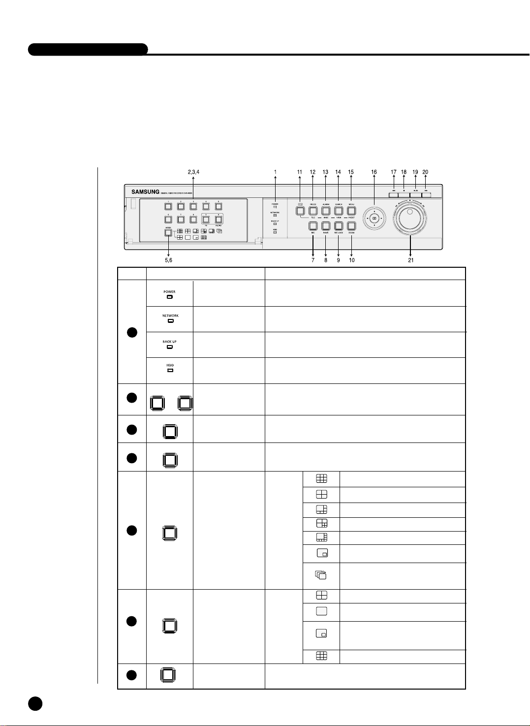
Part Names and Functions
1-3
No Name Function
Channel Button
Play Back
Channel Button
Power LED
Network LED
Back Up LED
HDD Access
LED
Split Screen
Selection
Button
Mode Selection
Button
REC Button
Display
Mode
Search
Audio Setup
Button
Displays power on/off condition.
Displays both network connection and data transmission conditions.
Displays Back Up Mode.
Indicates Normal Access to HDD.
Upon Access to HDD, LED repeats on and off.
Selects Single Channel in the Display Mode.
Used for Number Input Button in the Number Input Mode.
Recording starts as set in the Normal Record Mode
while LED is on.
5
1
2
3
4
...
1 8
9
0
MODE
6
7
MODE
REC
Displays the Play Back screen.
Sets up Audio On/Off.
9 Displays Split Screen.
8 Displays Split Screen.
4 Displays Split Screen.
6 Displays Split Screen.
7 Displays Split Screen.
Displays PIP(Picture In Picture)
Screen.
Auto Sequence Mode
Enters Single Channel Screen
by the time set in MENU.
4 Displays Split Screen.
Displays the selected channel
in Full Screen.
Displays both LIVE Channel and
Play Channel in PIP Screen
simultaneously.
9 Displays Split Screen.
Page 11

1-4
PANIC Button
REC LOCK
Button
PANIC
REC LOCK KEY
No Name Function
ALARM(WIDE)
MENU(PRESET)
Button
ZOOM Button
PTZ Button
SEARCH
(
VIEW
) Button
FREEZE(TELE)
Button
Direction
Control Button
Search
Function Key
Video/Audio set in the system records signals realtime. The recording resolution is Level 8 with a normal size.
Locks the REC key motion.
Sets up Digital Zoom(x2).
Performs the TELE, WIDE, PRESET, and VIEW function by pressing the PTZ button.
Performs the FREEZE function in the DISPLAYMode.
Performs the TELE function by pressing the PTZ.
Cancels the preset ALARM function to set up a new ALARM
function
.
Performs the WIDE function by pressing the PTZ
Indicates the Search method.
Performs the VIEW setup function by pressing the PTZ.
Displays the system setup menu or enters an upper menu.
Performs the PRESET setup function by pressing the PTZ.
Changes or edits the left setup value for the
detailed menu item setup.
Moves the cursor up in a menu or increases the
setup value for the detailed menu item setup.
Changes or edits the right setup value for the
detailed menu item setup.
Moves the cursor down in a menu or decreases
the setup value for the detailed menu item
setup.
Acts as the Enter key for the menu setup.
Views the fast rewinding search screen.
Stops file searching.
Toggles during playback to activate
PLAY/PAUSE or PLAY.
Views the fast forwarding search screen.
JOG : Used for the Forward/Reverse
Frame search.
Shuttle : Performs the Play/Reverse Play
/FF/REW function.
8
9
10
11
12
13
14
15
16
17
18
19
20
21
PTZ
FREEZE
TELE
ALARM
WIDE
SEARCH
VIEW
MENU
PRESET
ZOOM
➛
❿
❷
➛
Fast
Reverse
STOP
PLAY/PAUSE
Fast
Forward
JOG/
SHUTTLE
JOG SHUTTLE
Page 12

SHR-4080P USER’S MANUAL
1-5
13
1
2
3
5 6 7 8 9 10 11
4
12
Caution
Caution
Do not play DVR on the carpet or other soft material to prevent clogging of the air
ventilator.
To play DVR on the cabinet or rack, be sure to check the ventilation condition.
No Name Function
Composite Video Signal Input Port (BNC Style
Connector)
You may use THROUGH port to transmit a video
signal to the other video equipment.
Audio Signal Input Port (RCA Jack)
SPOT Out Output Port (BNC Style Connector)
Composite Video Signal Output Port (BNC Style
Connector)
Audio Signal Output Port (RCA Jack)
VGA Video Signal Output Port
S-VIDEO Video Signal Output Port
Network Connection Port
SCSI Type Device Connection Port
IEEE1394 Type Device Connection Port
- ALARM IN 1~8 : Alarm Input Port
- ALARM RESET IN : Alarm Reset Port
- ALARM OUT1~4 : Alarm Output Port
- TX+, TX-, RX+, RX- : RS-485 Communication
Port
AC 100~230V Power Socket Support
VIDEO IN
THROUGH
AUDIO IN
SPOT
VIDEO OUT
AUDIO OUT
VGA
S-VIDEO
NETWORK
SCSI
IEEE1394
ALARM
AC-IN
5
6
7
8
9
10
11
12
13
1
2
3
4
Page 13

Chapter 2 Installation
2
Page 14

1
Installation Environment Setup
2-1
Do not play DVR on the carpet or other soft material to prevent clogging of the air
ventilator. To play DVR on the cabinet or rack, be sure to check the ventilation condition.
You shall pay attention to the following before you use the product.
1. Do not use it outdoor.
2. Do not let water or liquid in the connection part or the product itself.
3. Do not impose excessive shock or force.
4. Do not pull out the power plug unreasonably.
5. Do not disassemble the product on your own.
6. Do not exceed the rated input or output range.
7. Use certified power cord only.
8. Match a product with an input ground with a power cord with a ground.
SHR-4080P USER’S MANUAL
Page 15

2
Checking Product & Accessory
2-2
Upon delivery of a product, you shall unwrap the product and put it on the even floor
or where you want to use it. Then you shall check if the following items are in it.
■ Main Body
■ User ’s Manual
■ One Power Cord
■ Two Brackets
- Brackets are used to attach the product to the rack.
■ Smart Viewer Software CD (Incl. PDF Manual)
■ 12 Screw Specials
- Please keep screw specials well to be used for HDD addition.
■ 2 EA of RS-485/Alarm Terminal Block
Page 16

SHR-4080P USER’S MANUAL
3
HDD Addition
2-3
You may add up to 3 more HDDs to the product.
However, since the product contains has many parts which may incur electric shock,
accident, or product breakdown and improper installation or setup may disturb HDD
recognition or normal product operation, you shall consult with an expert of the
agency where you bought the product.
[Caution for HDD Addition]
■ Do not let the cable stuck improperly nor uncoated. (This may cause breakdown or fire.)
■ Be careful not to cut yourself by sharp edges of the product.
■ Be careful not to miss the disassembled screws or parts. Imperfect assembly due
to short of screws or parts may cause breakdown or malfunctioning.
[HDD Addition Procedure]
1.Loosen screws on both sides(5 points) and back(1 point) to detach the product cover.
D
IG
IT
A
L V
ID
E
O
R
E
C
O
D
E
R
S
H
R
-40
80
Page 17
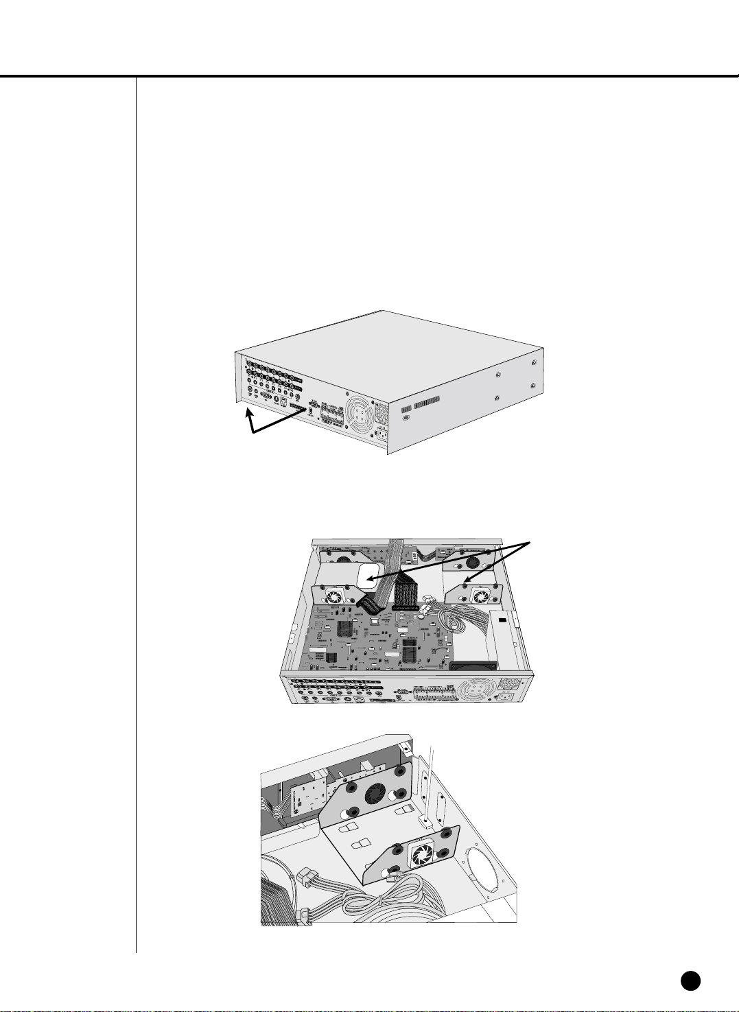
2-4
2.Detach the cover from the product. (Pull out the cover slightly and lift from the back
side to detach.)
3. Abracket is fixed to each side of HDD. Please loosen the screw of the bracket to
which you want to fix HDD.
BRACKET-HDD
Page 18

SHR-4080P USER’S MANUAL
2-5
4.Pull BRACKET-HDD to the product center to detach the fixed part at the bottom to
detach BRACKET-HDD from the product.
5.Tighten 4 SCREW-SPECIALs(BWH,6-32UNC,L10.5), supplied as an accessory to
fix HDD to BRACKET-HDD. (Screw tighten force shall be strong enough to resist
vibration.)
Page 19

2-6
6.
Restore HDD installed BRACKET-HDD.
(Assembly shall be done in the reverse procedure of disassembly as follows. Align the 5 fixing points at the bottom with the BRACKET-HDD fixing holes respectively and push BRACKET-HDD out of the product to align the screw fixing holes. Then, tighten the screws firmly.)
7.Check if BRACKET-HDD has been fixed to the product and connect both the power
supply cable and the signal transmission cable (IDE CABLE) to the HDD.
Signal Transmission
Cable (IDE Cable)
Power Supply Cable
Page 20

SHR-4080P USER’S MANUAL
2-7
8.Check the connector, wiring, and cable fixing condition inside the product and close
the cover.
9.Tighten cover-fixing screws. (5 points on both sides and 1 point in the back side)
✻ You can apply 2 HDDs to each BRACKET-HDD as shown in the figure.
Attention
Attention
For HDD addition, please select the same HDD with the existing HDD fixed to the
product as far as possible. This product can accept 4 more HDDs, 2 at Primary Slot
and 2 at Secondary Slot respectively. Both HDDs attached to Primary Slot and
Secondary Slot shall be set to Master and Slave respectively. Refer to User’s Manual
for Master or Slave Jumper Setting.
In the event of only one HDD installation, it shall be inserted into the Primary slot.
Note
Note
Refer to Appendix 2 to see which HDD specifications are supplied.
Page 21

2-8
Attention
Attention
! Regarding the sub fan, you need additional brackets and sub fans as follows.
The sub fan is shaped like this when viewed from the front and back. Please pay
attention to the fan direction to let wind go through the fan.
@ Fix the fan as follows.
Page 22

SHR-4080P USER’S MANUAL
2-9
# Please install the fan to be seen from the front view of the set.
Page 23

2-10
Fixing the fan to the left.
Page 24

Chapter 3 Connecting
with Other Equipment
3
Page 25

1
Connecting Video, Audio, and Monitor
3-1
SHR-4080P USER’S MANUAL
Page 26

2
Connecting SCSI Device
3-2
● The SCSI interface of SHR-4080P is used for backup or extended storage.
Connect an armored SCSI hard disk drive cable to the high-density 50-pin female
Ultra SCSI port. SCSI device ID adopts 0 through 5 with 6 connections at most.
Caution
Caution
Never connect or disconnect a SCSI device while DVR is turned on.
The system is not able to recognize the SCSI device while DVR is running.
Note
Note
The SCSI bus shall be terminated properly. Otherwise it may not operate.
Refer to Appendix 2 to see which HDD specifications are supplied.
Page 27

SHR-4080P USER’S MANUAL
3
Connecting Network
3-3
● Connecting to Internet through Ethernet(10/100BaseT)
● Connecting Internet through ADSL
Page 28

4
Connecting IEEE1394 Device
3-4
● Connect the IEEE1394 hard disk through the back port of SHR-4080P.
● You can connect up to 6 IEEE1394 armored hard disks by the Daisy-Chain
method.
● After connection, Menu - System - HDD Setup is necessary for recognition and
setup for use.
● It acts as HOT PLUG to connect or disconnect the IEEE1394 device while the sys-
tem is running.
● If you press Connect/Disconnect in Menu - System - HDD Setup, HOT PLUG will
be recognized or deleted.
Note
Note
See 5-8 System (HDD Setup) of User’s Manual.
Caution
Caution
- Wait until the HOT PLUG connected hard disk is stabilized enough (approx. 2 seconds per each hard disk) and click CONNECT in SHR-4080P MENU before use.
- Be sure to click DISCONNECT in SHR-4080P MENU to delete IEEE1394 Device
safely. Failure of clicking DISCONNECT may cause improper operation of IEEE1394
Device.
Caution
Caution
The IEEE1394 Device hard disk shall be set to Master.
Page 29

SHR-4080P USER’S MANUAL
3-5
Note
Note
Refer to Appendix 2 to see which HDD specifications are supplied.
Page 30

5
Connecting Alarm Input/Output
3-6
The Alarm IN/OUT port in the back of SHR-4080P is composed of the following
elements.
● ALARM IN/OUT Connection
Name Function
- ALARM IN1
- ALARM IN2
- ALARM IN3
1 - ALARM IN4 ALARM Input Port
- ALARM IN5
- ALARM IN6
- ALARM IN7
- ALARM IN8
- ALARM RESET IN On receiving an ALARM RESET signal, the
2 system cancels the current ALARM input or
output signal and resumes sensing.
- ALARM OUT1
- ALARM OUT2 ALARM Output Port
3 - ALARM OUT3
- ALARM OUT4
Page 31

SHR-4080P USER’S MANUAL
3-7
● ALARM IN/OUT Connection
Page 32

6
Connecting RS-485 Device
3-8
● Connect RS-485 Device through the back port of SHR-4080P.
● You can install and control the PTZ camera supporting RS-485 communication.
● You can adopt either Half Duplex or Full Duplex method for the connection.
● Baud Rate covers 600, 1200, 2400, 4800, 9600, 19200, and 38400.
Half Duplex Type
Data (–)
Data (+)
Full Duplex Type
Rx(+)
Rx(–)
Tx(–)
Tx(+)
Tx(–)
Tx(+)
Rx(–)
Rx(+)
PTZ Camera SHR-4080P
Rear
Caution
Caution
Check if RS-485 Device is compatible with SHR-4080P first. Then pay attention to
the polarity of RS-485 which has two poles, + and -.
Page 33

Chapter 4 Live
4
Page 34

1
System Motion
4-1
SHR-4080P USER’S MANUAL
● Turn the power on and the following LOGO screen pops up.
● After the LOGO screen appears, the button in front of SHR-4080P blinks 6 times
to initialize the system for operation.
● Upon completion of normal initialization, the Live screen appears accompanying a
beep sound.
● It requires 30 to 40 seconds until the Live screen appears.
Note
Note
A new HDD may require more time for the initialization until the Live screen
appears due to the initialization period of the new HDD.
If the Live screen does not appear at all or the button in front of SHR-4080P repeats
blinking, please check the connection across the product body. If you find any error,
please ask the shop where you bought the product.
Note
Note
If you see no more Live screen, you shall check if video data comes out in Composite
mode or VGA mode.
If you whish to change the video output mode, you shall hold on to the MODE button in front of SHR-4080P and keep pressing the 0 button for 5 seconds. Then, the
front button will repeat on and off.
● The Live screen does not affect the earlier MENU setup. If you reboot the system
after power-off during recording, the Live screen will appear, accompanying
recording.
Page 35

2
Livescreen Mode
4-2
Definition of Live Screen Icon
The Live screen icons of SHR-4080P display the current setup and function status of
each screen.
PTZ
N
CAM_01
CAM_01
V.Loss
: Recording Icon
Each icon represents Normal / Panic / Event(Alarm+Motion) / Schedule Recording.
: Recording Video Size Icon
Each icon represents the recording size of Large(Full D1: 720x576) / Normal(Half D1:
720x288) / Small(CIF: 352x288).
: PTZ Icon
This icon appears when you set up PTZ device with the PTZ icon and turns yellow
when you execute PTZ.
: Audio Icon
This icon represents Audio On/Off status and turns yellow for On. It does not appear
for Video or Audio Disable.
: Sensor In Event Icon
This icon appears in the channel synchronized with the external sensor signal input
with Sensor On.
: Motion Event Icon
This icon appears in the Motion Event channel with Motion Detection On.
: Zoom Icon
This icon appears with Zoom On or Zoom In and disappears when you cancel Zoom On.
: Freeze Icon
This icon appears in the Freeze mode and disappears when you cancel Freeze.
P ES
LNS
PTZ
Page 36

SHR-4080P USER’S MANUAL
4-3
Definition of Live Screen Mode
SHR-4080P receives 8 live images and displays them in the following 8 modes.
● Full Screen(Single) Mode:
Displays the selected channel in a full screen. Then, the channel LED concerned
will be turned on.
● 4, 6, 7, & 8 Split Mode:
Four, six, seven, and eight video channels are split in the screen and each channel LED is turned on. You are able to choose a channel as you want to in each
split mode.
● 9 Split Mode:
Splits all the video input from CH1 to CH8 into 9 screens and LEDs of CH1 to CH8
are all turned on. You are not allowed to choose a channel in this mode.
● PIP(Picture in picture) Mode:
Displays a one-ninth sized screen in the full screen and the channel LED concerned is turned on. You are able to choose a channel as you want to, which is
displayed in the full screen or reduced screen area. You may move the PIP screen
at 5 stages in the Full screen with the or ❷key.
● Auto sequence Mode:
Displays the time when FULL SCREEN has been set to each channel in sequence
and the channel LED concerned is turned on.
CAM_01
CAM_03 CAM_04
CAM_01 CAM_02
CAM_01
CAM_04 CAM_05 CAM_06
CAM_03
CAM_02
CAM_03
CAM_04 CAM_05
CAM_07CAM_06
CAM_01 CAM_02
CAM_01
CAM_05 CAM_06 CAM_07 CAM_08
CAM_04
CAM_03
CAM_02
CAM_01
CAM_02
CAM_01
CAM_01 CAM_02
CAM_03
CAM_06
CAM_05
CAM_08
CAM_04
CAM_07
Single Mode
Quad 1,2 Mode 6 Split Mode
8 Split Mode 9 Split Mode PIP Mode
Auto sequence Mode
7 Split Mode
: Auto Sequence Icon
This icon appears in the Auto Sequence mode.
V.Loss / V.Off : Video Input Status
If there is no more video data input with Video On, [V.Loss] appears in the channel. If
you set Video On/Off to Off, [V.Off] will appear.
Page 37

4-4
Selecting Live Screen Mode
Each mode may be selected by [MODE Button] and [CH1 ~ CH8 Button]. The following figure shows Live Mode of SHR-4080P after converted.
● The default is 9 Split Screen Mode.
● The default of 4 Split Screen Mode is [4 Split 1] Mode to display [CH1 ~ CH4] or [4
Split 2] Mode to display [CH5 ~ CH8].
● You are able to choose other modes than Full Screen Mode with [MODE Button] in
sequence. Whenever you press [MODE Button], the system will enter [9 Split]➝[4
Split 1]➝[4 Split 2]➝[6 Split]➝[7 Split]➝[8 Split]➝[PIP]➝[Auto sequence]➝[9 Split]
Mode one by one.
● If you press [CH1~CH8 Button], you will be able to see the full screen of each
channel.
● The MODE button is used to return to the previous split mode screen from a full
screen mode.
Page 38

3
Live Channel Selection and Audio On/Off Setup
In other split modes than Full Screen Mode, 9 Split Mode, and Auto Sequence Mode,
you may choose a channel to be displayed in each split area on your own. Meanwhile,
the channel whose MENU is set to Audio On can set up Audio On/Off in all Live Modes.
Audio On/Off Setup in Full Screen
In Full Screen Mode, the selected channel Audio is automatically turned on and you
may set up Audio On/Off with the Audio Setup button [0 Button]. Depending on the
Audio On/Off setup condition, the Audio Setup button [0 LED] is turned on or off.
Audio On/Off Setup in 9 Split Mode
If you press [ENTER Button] in 9 Split Mode, the selection cursor in the following figure
will appear and the channel concerned will be selected. If you press the Audio Setup
button [0 Button] with a channel selected, you may set up Audio On/Off for the channel
concerned. Depending on the Audio On/Off setup condition, the Audio Setup button [0
LED] is turned on or off. You are not allowed to choose a channel in this mode.
SHR-4080P USER’S MANUAL
4-5
Channel Selection and Audio On/Off Setup in 4,6,7,8 Split
Mode and PIP Mode
As in 9 Split Mode, the selection cursor will appear if you press [ENTER Button] in both
4,6,7,8 Split Mode and PIP Mode to select a channel. With a channel selected, you may
not also choose a channel on the current screen with the [CH1 ~ CH8] button but also
set up Audio On/Off with the Audio Setup button [ 0 ] as in 9 Split Mode. Depending on
the Audio On/Off setup condition, the Audio Setup button [ 0 ] is turned on or off.
Audio On/Off Setup in Auto Sequence Mode
The default of Auto Sequence Mode is set to Audio On and Audio changes channel by
channel. You may set up Audio On/Off with the Audio Setup button [0 Button] and the
Audio Setup button [0 LED ] is turned on or off depending on the Audio On/Off setup
condition.
CAM_01
CAM_02
CAM_03
CAM_06
CAM_05
CAM_08
CAM_04
CAM_07
Page 39

4-6
4
Freeze and Zoom
Freeze Function
Freeze pauses the video image in Live Screen, only available in Live Mode. You can set
up Freeze On/Off with [FREEZE Button] and [FREEZE LED] is turned on or off depending on the Freeze On/Off setup condition.
Zoom Function
Zoom enlarges the selected area twice, only available in Full Screen Mode.
If you press [ZOOM Button] in Full Screen Mode, the zoomed area will appear now you
are able to adjust the selected area position. If you select an area and press [ENTER
Button], the area will be displayed in double size. If you press [ENTER Button] again,
the previous screen to select Zoom area will appear again and you will be capable of
Zoom Off with [ZOOM Button] after the screen is enlarged. Depending on the Zoom
On/Off setup condition [ZOOM LED] is turned on or off.
Page 40

5
Event Monitoring
Event Monitoring displays the channel synchronized with a specific event
(Sensor/Motion/Video Loss) on the screen when it occurs. Event Monitoring On/Off
and Event Duration setup is available in [Menu]➝[Monitoring].
If you set the Event Monitoring interval to 5 seconds and an event occurs at CH2 in
the beginning as in the following figure, the system will display CH2 in the whole
screen for 5 second. Another event within 5 seconds will be displayed together with
the existing event. In the following figure, both CH1 and CH3 events occur within 5
seconds (for example, in 4 seconds) after the CH2 event, the three events are split
into 4 screens.
Likewise, CH2, CH5, and CH7 events within 5 seconds after both CH1 and CH3
events are integrated with the existing 2 events and all the 5 events are split into 9
screens. Without further event during Event Duration, the system will return to the previous Live Mode.
If you press [ALARM Button] during Event Duration, Event Monitoring will stop. On
sensing an event, [ALARM LED] is turned on. If you press [ALARM Button] now,
[ALARM LED] will go out.
Audio On/Off setup is also available during Event Monitoring and its default is set to
Audio On. In case of event occurrence at a certain channel, Audio of the channel is
On while the lowest channel Audio is on in case of simultaneous occurrence of more
than one event since the lowest channel has the first priority. You may use [CH0
Button] to alter the Audio On/Off setup condition, on the basis of which [CH0 LED] is
turned on or off.
SHR-4080P USER’S MANUAL
4-7
Page 41

4-8
6
Spot-out Monitoring
Spot-out Monitoring has nothing to do with Live Screen Output, monitoring the full
screen of a certain channel. If you select Monitoring in the MENU screen, you can
make a channel among CH1 to CH8 spot out or you can output channels one by one
at an interval as Auto Sequence Mode of Live Mode. The interval is as same as the
forwarding time of Auto Sequence Mode of Live Mode. If you set Spot-out Event
Monitoring to On, you will be able to spot out the event channel. In case of simultaneous event occurrence at more than one channel, the lowest numbered event channel
has the first priority to be spotted out.
Caution
Caution
If the built-in HDD is not connected, or it operates with power applying in error,
( ) indicating "built-in HDD error" is displayed at the top of left.
At this time,
(1) Live screen mode
(2) Monitoring mode by Smart Viewer
operate only and the other functions including recording, search, playback, menu
setup, and PTZ do not operate.
If the above problem is occurred, Be sure to contact a service center to settle the
problem.
Page 42

Chapter 5
Menu Setup
5
Page 43

Before Use
5-1
● Selection
The yellow cursor shows the current window. Use the ,❷,➛, or ❿ key in the
front to move the cursor on your desirous menu. If you press the “Enter” key with
the cursor clicking on your desirable menu, the system will enter the new mode.
Press the “Enter” key to finish selection. On seeing Drop Down Menu, use the
or ❷ key to move the cursor on your desirable menu.
● “OK” or “Cancel” in Menu Setup Window
Once changed, the new menu setup procedure will be finalized by pressing “OK”.
Pressing “Cancel” will cancel the previous setup and return to the upper menu.
● Front “MENU” and “SEARCH” Button
The MENU button or SEARCH button, if pressed first, acts as an entrance button.
Once entering, it reverses the page to the previous one.
● The “>” or “V” mark beside the title copies the line in the arrow direction to the
value of the first line.
● The first page of the menu is structured as follows.
SHR-4080P USER’S MANUAL
Page 44

1
System
5-2
● System Menu has the following items in detail.
● Date
Press the “Enter” key and the ➛ or ❿ key to move to Y/M/D. Use the or ❷ key
to change the date. Press the “Enter” key to come out of the mode.
● Time
Press the “Enter” key and the ➛ or ❿ key to move to H/M/S. Use the or ❷ key
to change the time. Press the “Enter” key to come out of the mode. Once changed,
the date and time will remain unchanged until you press “OK” or “Cancel”.
Date/Time/Language Setup
Page 45

SHR-4080P USER’S MANUAL
5-3
● Date Format
This supplies 3 formats, Year-Month-Date / Date-Month-Year / Month-Date-Year.
● Time Format
This supplies 2 formats, 24 Hour / 12 Hour(AM/PM).
● Language
After you select a language, OSD is expressed in the selected language. The
available languages are added in the list.
● Summer Time
Summer Time sets the watch one hour faster than the local standard time. This
makes the system count for Summer Time in Summer Time regions. Being the
Summer Time setup date, the set goes one hour faster and starts rebooting.
Set to Off, Summer time does not operate. Then, you are unable to enter the right
date menu. Set to On, you can set the start time on the left and the end time on
the right on the basis of ‘~’. Summer Time is allowed to set Month/Date/Time only.
Year/Minute/Second remains inactivated.
Note
Note
[Date/Time Change]
Pressing “OK” after you change date and time, you will be asked by a pop-up window if you really confirm the change. Here, press “Yes” to change the time. Since
Date/Time does not change in backup/recording process, be sure to stop the
backup/recording process before you change Date/Time.
Note
Note
[Summer Time Setup]
Backup in progress will be cancelled. Recording in progress will be suspended for a
moment until rebooting.
Caution
Caution
[Date/Time Change]
If you restore Date/Time to the original value, the data recorded before the restoration may be deleted. For example, if you restore 8 am to 7 am, all the data recorded
between the times will be deleted.
Caution
Caution
[Summer Time Setup]
As the system goes one hour earlier, the data recorded since an hour ago will be
deleted. As Summer Time activates at the preset time, you are recommended to take
the utmost care of preventing any trouble incurred by data deletion or rebooting.
Page 46

5-4
Password
● The Default Password is 4321.
● New Password
This is used to change the system password inside SHR-4080P. You are allowed
to create a password up to 8 digits. Press the “Enter” key and then a channel button from 0 ~ 9 on your left to finish input. If you press the “Enter” key after change,
the system will automatically turn to “New Password Confirm”.
● New Password Confirm
This confirms a new password. You shall be obliged to input New Password in the
above row first. Without New Password input, New Password Confirm input has no
effect.
● Password Lock
Pressing the “Menu” button while it is set to On, you will be asked by a pop-up
window of the password. Pressing the “Menu” button while it is set to Off, you will
enter Menu Mode immediately, not being asked of the password.
● All Key Lock On
If you select this, the system will enter Live Mode immediately. If you press a button in the front, the Password window will pop up. Succeeding in Password input
will be followed by Key Lock cancellation after such a message window pops up.
Note
Note
[All Key Lock On]
If you select this, the system will enter Live Mode immediately and keys will be
locked.
Page 47

SHR-4080P USER’S MANUAL
5-5
Load Factory Default
● This initializes all the menu preset values. The recorded data will not be deleted.
Press “OK” in the confirmation window to start initializing.
System Log
● System Log is used by a controller to check crucial records.
● This displays such contents of a system related log and its execution date/time as
System Start, System Termination, and Menu Setup Change.
● First : Returns to the first Log page.
● Prev : Back to the previous Log page.
● Next : Forwards to the next Log page.
● Last : Moves to the recent Log.
Page 48

5-6
● System Log List
Event Log
● Checks the record regarding Event like Alarm / Motion / Video Loss
● This displays the contents of a log regarding Event its execution date/time.
● First : Returns to the first Log page.
● Prev
: Back to the previous Log page.
● Next : Forwards to the next Log page.
● Last : Moves to the recent Log.
● Event Log List
System Start System Start Panic Record Start Panic Record Start
Login(Admin) Viewer Login (Admin) Panic Record End Panic Record End
Logout(Admin) Viewer Logout (Admin) Time Change Date/Time Change
Login(User) Viewer Login (User) Load Factory Default System Initialization
Logout(User) Viewer Logout (User) System Upgrade System S/W Change
Setup Start (Local) Set: Menu Entering Disk Full No Space for HDD
Setup End (Local) Set: Menu Escape Backup Start Backup Start
Setup (Remote) Viewer:Menu Setup Backup End Backup End
Play Back Start Play Start Backup Stop Backup Stop
Play Back End Play End Backup Fail Backup Failure
Record Start CH[n]
Channel [n] Record Start
ATA HDD Erase ATAData Deleted
Record End CH[n] Channel [n]
Record
End IEEE1394 HDD Erase IEEE1394 Data Deleted
Power Failure Recovery System Restoration
SCSI HDD Erase SCSI Data Deleted
after Power Failure
Video Loss CH[n] Channel [n] Image Disturbance
Alarm Detection CH[n] Channel [n] Alarming
Motion Detection CH[n] Sensing Channel [n] Motion
Page 49

SHR-4080P USER’S MANUAL
5-7
System Information and Setup
● Software Version : Displays the current version. Setup is not available.
● Broadcast Format : Displays the current Format(NTSC/PAL) . Setup is not avail-
able.
● Mac Address : 6 Byte hardware address. Setup is not available.
● HDD Erase
This erases the data in ATA / IEEE1394 / SCSI. Click the checkbox of the device
that you want to erase and press “OK” You are not allowed to erase the data in
Recording or Backup progress.
Note 1
Note 1
Being a physical hard disk inside the SHR4080 main body connected by an IDE
cable, this stores data.
[External HDD]
Being a physical hard disk connected with the port and terminal in the back of the
SHR4080 main body, this stores data.
This can be used as Extended HDD or Backup HDD.
- Extended HDD : Supplements Internal HDD quantity. Connected, it takes the place
of Internal HDD.
- Backup HDD : Backs up the data recorded in the set.
Note 2
Note 2
[ATA]
Usage : Internal HDD
[SCSI]
Usage : External HDD (Extended HDD or Backup HDD)
A physical hard disk connected with the SCSI port in the back of the SHR4080 main
body
[IEEE1394]
Usage : External HDD (Extended HDD or Backup HDD)
A physical hard disk connected with the IEEE1394port in the back of the SHR4080
main body
Page 50

5-8
HDD Setup
Internal
● HDD Information
Displays the number, quantity, and status of ATA, IEEE1394, and SCSI. Setup is
not available.
Status : Internal HDD, External HDD, Backup HDD
● External HDD Setup
1. Backup/External
You are able to determine the usage of IEEE1394 and SCSI.
Not Defined ➝ When the connected HDD usage is not defined. Expressed in
External or Backup.
No Device ➝ When no HDD is connected. You are able to press right TAB after
you connect HDD.
External ➝ When the connected HDD is set to External. It may used as a back
up HDD if you press the “Enter” key and turn to Backup.
Backup ➝ When the connected HDD is set to Backup. It may used as an
External HDD if you press the “Enter” key and turn to External.
Caution
Caution
[HDD Erase]
Data will not be deleted in backup or recording process.
Please be sure to suspend backup or recording before you delete any data.
Page 51

SHR-4080P USER’S MANUAL
5-9
2. Hot Plug - Connect/Disconnect
You may connect or disconnect IEEE1394 Hard Disk while power is supplied to
the SHR-4080P main body.
① As for connecting, connect IEEE1394 Hard Disk with the SHR-4080P main
body and press “Connect”. Pressing “Connect” makes the SHR-4080P main
body recognize all connected IEEE1394 Hard Disks.
➁ As for disconnecting, be sure to press “Disconnect” and detach IEEE1394
Hard Disk from the SHR-4080P main body safely.(Be sure to pause recording
or backup process.) Pressing “Disconnect” cancels and detaches all
connected IEEE1394 Hard Disk.
Disk Mode Setup
● Disk End Mode
Stop : Stops recording when HDD is full during recording.
Overwrite : Deletes the original data and save a new data when HDD is full
during recording.
Please delete the HDD data to change the initial mode.
☛ To delete data, please refer to the following menu. 5-7. System Information and
Setup
● Disk End Beep
On : Beeps when HDD is full during recording.
Off : When HDD is full, the beep sound is not heard.
Caution
Caution
[ IEEE-1394 Hot-Plug Connect/Disconnect Function ]
You may connect or disconnect SCSI while power is supplied to the SHR-4080P main
body. Only IEEE1394 supports the Hot-Plug function.
[Backup HDD]
SCSI and IEEE1394 cannot be used as Backup HDD simultaneously.
IEEE1394 shall be set to External to use SCSI as Backup.
SCSI shall be set to External to use IEEE1394 as Backup.
Page 52

5-10
Remote control Device
MENU for Samsung Integrated Remote Control(SSC-2000)
Remote Control Device
ID Baudrate
Device Samsung System Keybord
Parity Date Stop Duplex
03 4800 None 8 1 Half Duplex
● Device
A Remote Control Device, being connected to the RS485 port.
● ID
Unique ID of SHR-4080P
This unique ID is essential as SSC-2000 can control multi SHR-4080 DVRs.
● Baudrate
Baudrate to communicate with SSC-2000
Be sure to be identical to SSC-2000 Baudrate for communication.
● Parity
Sets up one of None / Even / Odd.
● Data
Sets up either 7 or 8.
● Stop
Sets up either 1 or 2.
● Duplex
Sets up either Half Duplex or Full Duplex.
Caution
Caution
[Disk End Mode Overwrite]
In Overwrite Mode, the previous Event data may be deleted.
Note
Note
If you select Remote Control Device, you may not PTZ Camera with SHR-4080P. The
PTZ button in front of SHR-4080P becomes inactivated.
Press the PTZ button and the PTZ ban icon( ) will appear. It’s because the RS485 port setup was done for Romote Control Device.
Page 53

SHR-4080P USER’S MANUAL
5-11
System Shutdown
● Terminates the work in action safely and turns the power off. Press “OK” in the
confirmation window and plug out when you see “Safe to Power Off”.
Remote Control Device
Caution
Caution
[System Shutdown]
Power-off without terminating the system in the System Shutdown menu may incur
improper motion like
data loss and disk failure. Power-off shall be done in the
System Shutdown menu.
Page 54

5-12
2
Camera
● The detailed Camera Menu items are as follows.
● Video
On : Camera images from a selected channel appear.
Off : Camera images from a selected channel disappear. In this case, you are not
allowed to set Audio/Title/Auto Seq.
● Audio
On : You can hear voices from a selected channel.
Off : You cannot hear voices from a selected channel.
Camera Configuration
Page 55

● Title
You can name the camera of a selected channel.
If you press the Enter key, the Virtual keyboard will come out.
❿Virtual Keyboard
If you move the cursor, you can type text by text.
Up to 15 texts can be typed.
Keyboard cannot be composed of all spaces.
Pressing Caps Lock changes the keyboard that can be selected. (2 Modes)
● You may define the duration of each channel at the Auto Sequence channel in Live
Mode. Achannel, set of Off, does not operate in Auto Sequence Mode.
SHR-4080P USER’S MANUAL
5-13
Page 56

5-14
PTZ Device
● ID
PTZ Camera ID from 0 to 255
● Protocol
A protocol supported by PTZ Camera
The following protocols are now being supported.
Samsung/ Vicon/ Panasonic/ AD/ Philips/ Erna/ PelcoD/ PelcoP/Vcltp/ Diamond/
Kalatel
● Baudrate
Baudrate supported by PTZ Camera, 600/ 1200/ 2400/ 4800/ 9600/ 19200/ 38400
● Parity
Defines one among None, Even, and Odd.
● Data
Defines either 7 or 8.
● Stop
Defines either 1 or 2.
● Serial Mode
Defines either Half Duplex or Full Duplex.
Caution
Caution
The above items shall be aligned with the PTZ Camera setup condition.
For the details, please refer to User’s Manual of the PTZ Camera manufacturer.
Page 57

Screen Setup
SHR-4080P USER’S MANUAL
5-15
● This is a window to adjust Brightness/Contrast/Color for the camera image of each
channel. Put the cursor on the channel that you want to adjust and set up
Brightness/Contrast/Color. Once selected, the channel appear in the PIP area on
the right. Press the or ❷ key to adjust the value from 0 to 100.
● If you select CH ✓, all the channel values will become the same as the finally
selected channel value.
● “Default” resets the current channel to the basis value of 50.
Note
Note
[Screen Setup Change]
During backup or recording process, the Screen Setup information remains
unchanged.
Be sure to stop backup or recording process before you change the information.
Page 58

5-16
3
Monitoring
● Event Monitoring
You are able to set to Off/3sec/5sec/10sec/20sec/30sec/Continuous.
① Off : Event Monitoring does not operate to turn to the screen where an event
occurs.
➁ 3sec/ 5sec/ 10sec/ 20sec/ 30sec : For the period, the screen is seen before the
next screen appears.
➂ Continuous : The Event Monitoring screen remains alive until you press the front
“Alarm” button to cancel the screen manually.
● OSG Display
① Date :
The date is displayed on the screen or not depending Date remains On or Off.
➁ Time :
The time is displayed on the screen or not depending
Time
remains On or Off.
➂ Title :
The title is displayed on the screen or not depending
Title
remains On or Off.
➃ Status : Audio/Ptz is displayed on the screen or not depending Status remains
On or Off.
● Spot Out Channel
Spot Out channel is used to let one of two monitors monitor a channel, focusing on
it. Spot Out channel supplies two functions, continuous monitoring of only one
channel and Auto Sequence to display all the channels one by one.
① Auto Seq. setup ranges from Ch1 to Ch8.
➁ Set to Auto Seq., Spot Out channels are displayed in turn.
➂ Auto Seq. Duration is as same as determined for Camera Configuration.
● Spot Out Event Monitor
Determines if event monitoring will be executed for Spot Out channels.
① Off : dose not event monitoring in Spot out channel.
➁ 3sec/ 5sec/ 10sec/ 20sec/ 30sec : Duration options on the screen before it
scrolls down.
➂ Continuous : Once scrolled down, the screen remains displayed until you delete
“Alarm” LED in front manually.
Page 59

● Monitor Out
You are not allowed to connect VGA MONITOR and Composite MONITOR simultaneously. Consequently, the user are obliged to choose either Composite Output
or VGA Output.
① Composite : Output comes out of the “Composite Out” port.
➁ VGA : Output comes out of the “ VGA Out” port.
Any change from Composite to VGA or vice versa reboots the system
automatically.
● PB( Playback ) Channel Position
Designates the position of a channel to be played back in Play Back 9 Split Mode.
Right Down : Designates a location on the bottom right corner.
Center : Designates a location in the center.
SHR-4080P USER’S MANUAL
5-17
Caution
Caution
[Monitor Out]
Set to Composite Output, VGA does not come out.
Set to VGA, Composite Output does not come out.
If you hold on to the MODE button in Live Mode and keep pressing the 0 button for
5 seconds, the status will change from VGA to COMPOSITE or vice versa accompanying rebooting.
Page 60

5-18
4
Record Mode
If you press the front “REC” key, the mode to be recorded will be determined.
☛ For Event Recording Mode value setup, refer to 5-18. Event Record
Mode Setup Menu.
● Mode
On : Pressing the REC key starts recording the current channel.
Off : Even pressing the REC key does not affect current channel recording.
The default is set to “On”.
● Video Size
Determines the size of a screen to be recorded.
Full D1 : 720x576 (L) ➝ Large
Half D1 : 720x288 (N) ➝ Normal
CIF : 352x288 (S) ➝ Small
Note
Note
[Monitor Out]
You are not allowed to set up Video sized “Full D1” and “25ips” of Rate simultaneously. The system does not support both at once.
Note
Note
[Monitor Out]
You are not allowed to set up “25ips” of Rate and Video sized “Full D1” simultaneously. The system does not support both at once.
● Quality
Recording resolution will be determined.
Choose one from Level 1(Low) to Level 8 (High).
Level 8 supplies the best resolution
● Rate
Determines Frame Rate to be recorded. Frame Rate means the number of screen
recorded every second.
Set to 25ips, the system records too many screens per second and play continues
intermittently since recording is more detailed. This is appropriate for concentrated
monitoring zone setup.
25 ips/ 12.5 ips/ 8.33 ips/ 6.25 ips/ 5 ips/ 2.5 ips/ 1 ips
Page 61

5
Event Mode
● The detailed items of Event Record Menu are as follows.
Evnet Record Mode
Determines a mode to be recorded when an event occurs.
● V. Size (Video Size )
Determines the size of a screen to be recorded.
Full D1 : 720x576 (L) ➝ Large
Half D1 : 720x288 (N) ➝ Normal
CIF : 352x288 (S) ➝ Small
SHR-4080P USER’S MANUAL
5-19
Note
Note
[Monitor Out]
Simultaneous setup of "Full D1" in Video Size and "25ips" in Rate is prohibited. This
is not supported by the system.
Page 62

5-20
● Quality
Recording resolution will be determined.
Choose one from Level 1(Low) to Level 8 (High). Level 8 supplies the best resolution
● Rate
Determines Frame Rate to be recorded. Frame Rate means the number of screen
recorded every second.
Set to 25ips, the system records too many screens per second and play continues
intermittently since recording is more detailed. This is appropriate for concentrated
monitoring zone setup.
25 ips/ 12.5 ips/ 8.33 ips/ 6.25 ips/ 5 ips/ 2.5 ips/ 1 ips
● PreAlarm
● PostAlarm
Records the situation until Alarm is issued.
Off : No recording
5sec/ 10sec/ 20sec/ 30sec : The recording time options before Alarm issue
Records the situation since Alarm is issued.
Off : No recording
5sec/ 10sec/ 20sec/ 30sec/1min/3min/5min/10min/20min :
To this, the recording time after Alarm issue is set.
Note
Note
[Monitor Out]
You are not allowed to set up “25ips” of Rate and Video sized “Full D1” simultaneously. The system does not support both at once.
Pre Alarm Section
Event occurred point of time
Post Alarm Section
Event occurred point of time
Page 63

Alarm
● Sensor State
Off : Sensor does not operate.
① N.O(Normal Open) Sensor : Sensor remains open all the time and if closed, an
alarm will be issued. (A Contact)
➁ N.C(Normal Close) Sensor : Sensor remains closed all the time and if open, an
alarm will be issued. ( B Contact)
● Cam
Determines a camera which will synchronize with the current sensor.
The default is currently set to the sensor number. A sensor shall be synchronized
with at least a camera. Multi-synchronization is possible.
SHR-4080P USER’S MANUAL
5-21
OK Cancel
Sensor Sensor State
Alarm-Out
Cam
Beep-Out
1 N.O
None
1
10sec
2 Off
10sec
3 Off
10sec
4 Off 10sec
5 Off
10sec
6 Off
10sec
7 Off
None
1 10sec
8 Off
None
0 10sec
OK Cencel
CHO4
CHO7
CHO2
CHO5
CHO8
CHO3
CHO6
All
CHO1
Alarm
● Alarm-Out
Arranges Alarm-Out when Alarm Sensor sounds.
At this moment, this supports 5 Alarm Outs. Choose an alarm-out that you want to
synchronize with the current sensor. Multi-choice is possible.
● Beep-Out
Determines Alarm-Out Duration. Alarm-Out continues for the determined duration.
Off/ 3sec/ 5sec/ 10sec/ 20sec/ 30sec/ 1min/ 2min
Page 64

5-22
Motion Detecting
● M.D State
Off : Motion Detection does not operate
On : Motion Detection starts operation.
● Area
Select the Motion Detection zone. It is composed of 45x48 sized Block. You are
forbidden to determine 4 block rows(Up/Down/Left/Right) to allow them to be
displayed in all monitors.
❿ Select All : Selects the whole area.
❿ Select One : Selects a block every time. Selection is done by a toggle system.
❿ Select Quarter : Split the whole area into 4 pieces, which enables selecting a
fourth of the whole area.
❿ Clear All : Cancels the whole area.
❿ Save & Exit : Saves and exits.
❿ Exit : Exits without saving.
Page 65

● Sensitivity
Determines Motion sensing sensitivity. Sensitivity grade consists of Low ➝
Medium ➝ Very High in the ascending order.
● Alarm-Out
Selects Alarm-Out scope when Motion occurs.
At this moment, this supports 5 Alarm Outs. Choose an alarm-out that you want to
synchronize with the current motion channel. Multi-choice is possible.
● Beep-Out
Determines Alarm-Out Duration. Alarm-Out continues for the determined duration.
Off/ 3sec/ 5sec/ 10sec/ 20sec/ 30sec/ 1min/ 2min
Video Loss
SHR-4080P USER’S MANUAL
5-23
● Video Loss State
Off : Video Loss does not operate.
On : Video Loss starts operation.
● Alarm-Out
Selects Alarm-Out scope when the current Video Loss occurs.
At this moment, this supports 5 Alarm Outs. Choose an alarm-out that you want to
synchronize with the current motion channel. Multi-choice is possible.
● Beep-Out
Determines Alarm-Out Duration. Alarm-Out continues for the determined duration.
Off/ 3sec/ 5sec/ 10sec/ 20sec/ 30sec/ 1min/ 2min
Page 66

5-24
6
Record Schedule
You may select a time when recording starts automatically.
Selection by the day or by the time is available.
The default is set to “None”.
● Pressing “CH > “ copies the value of Channel 1 to all the channels.
● The horizontal axis numbered from 0 to 23 represents the time value.
The vertical axis numbered from S to H represents the day value. (H :Holiday)
Selection by the day or by the time is available.
● Pressing “ALL” converts the overall setting of the selection window into
Continuous➝Event➝Both➝None.
● Continuous Recording
Recording starts automatically on the preset time.
Recording follows the condition established in 5-17.Record Mode of MENU.
☛ Refer to 7-3 Record Schedule of MENU.
● Event Recording
Recording starts automatically when Event occurs to Alarm/Motion Detection/Video
Loss within a designated time.
Recording follows the condition established in 5-18.Event Record Mode Setup of
MENU.
☛ Refer to 7-4 Event Recording of MENU.
Page 67

● Both(Continuous, Event)
On occurrence of Event, Continuous Recording is replaced with Event Recording
Mode.
● Holiday
If you press “Holiday”, a calendar pops up and you are able to designate holidays.
Move to a date and press “Enter” to complete designation.
Press “Enter” once more to cancel designation.
“H” at the bottom of the table means a holiday.
SHR-4080P USER’S MANUAL
5-25
Page 68

5-26
7
Backup
● Sel Tap is not checked in the beginning.
Once checked, Sel Tap activates “Start” and free space is displayed in the Free
Space zone.
● Set the date and time that you want to back up and press “Start” to start Backup.
When you change Start Date/Time or End Date/Time, free space keeps updated in
the Free Space zone.
● Set to First On, Backup is set to the date of the initial data and the time is inactivated.
● Set to First Off, Backup cancels Dim so that you can set a date on your own.
● Set to Last On, Backup is set to the date of the initial data and the time becomes dim.
● Set to Last Off, Backup cancels Dim so that you can set a date on your own.
● Without Backup Device, Warning sign pops up.
Select and connect Backup Device in 5-8.HDD Setup of MENU and proceed with
Backup.
● With more than 2 Backup Devices connected, Warning sign pops up.
More than one Backup Device is prohibited in Backup process.
Backup setup is allowed for either SCSI or IEEE1394 of 5-8.HDD Setup in MENU.
● Press “Stop” to stop Backup.
● Pressing Cancel during the Backup returns to the upper menu but this does not
affect Backup process.
Note
Note
[Backup Device]
Without Backup Device or with more than one Backup Device, Backup does not
start. Check if only Backup Device is connected before you proceed with Backup.
Caution
Caution
[In Backup Process]
Pressing Cancel returns to the upper menu but this does not affect Backup process.
Press Stop to suspend Backup. Backup may possibly slow the speed of the set.
Page 69

8
Network
● Connection Mode
Designates the kind of the network connected to the main body of SHR-4080P.
Static IP : When the main body is connected to the network with Static IP.
Dynamic IP : When the main body is connected to the network with Dynamic IP
supplied by DHCP.
ADSL(PPPoE) : When the main body is connected to the ADSLnetwork with PPPoE.
● Bandwidth
Designates the network speed to which the main body of SHR-4080P is connected.
Unlimited / 2 Mbps / 1 Mbps / 600 Kbps / 300 Kbps
● Admin Password
The password for the connection between Smart Viewer and the set with the authority
of Admin. The password can be as long as 8 digits.
Press "Enter" and the left number keys from 0 to 9 for setup.
● User Password
The password for Smart Viewer’s access to the set with the authority of general user.
● IP (Port)
So sets up the IPAddress and Port number as to connect the main body of SHR-4080P
with the network. If the Connection Mode is set to Static IP, you shall type in IP yourself.
If the connection mode is Dynamic IP or ADSL(PPPoE), the IP allocated by the DHCP
server or ADSLcompany will be automatically displayed. In case of failure of DHCP or
ADSL connection, 000.000.000.000 will be displayed. Then, press OK to retry connection to get a new IP. If you continue to fail in DHCP or ADSLconnection, keep the main
body of SHR-4080P off for a while and turn it on for retry. The Port number indicates the
4 ports by which the main body attempts network connection. The default is 554, 555,
556, 557. You may change the Port number under circumstances. The Port number will
be altered in group of 4 consecutive numbers. If you allocate different Port numbers to
each main body and IP Router while you use IP Router to connect multi SHR-4080Ps,
you can compose a network through port forwarding.
SHR-4080P USER’S MANUAL
5-27
Netwrok
Connection Mode
Bandwidth
Admin Password
User Password
IP(Port)
Gateway
Subnet Mask
DNS
ADSL User ID
Password
Static IP
2 Mbps
*************
*************
192.168.001.201(554.555.556.557)
192.168.001.001
255.255.255.000
168.126.063.001
ID
*************
Caution
Caution
When the main body is connected to the network using high speed LAN, set to 1
Mbps or 2 Mbps. When the main body is connected to the network supporting low
bandwidth such as ADSL, set below 600 Kbps. If you set Bandwidth high though the
main body is connected to a slow network, the network load will get heavy therefore
the connection with Smart Viewer or video monitoring may be instable.
Page 70

5-28
Note
Note
If you want to connect IP Router with the main body of SHR-4080P, you shall designate
a port for SHR-4080P in the IP Router setup menu.
The main body of SHR-4080P uses 4 ports for TCP communication.
In addition, if you want to use the DHCP function backed by IP Router to allocate
Dynamic IP to the main body of SHR-4080P, you shall designate a port for the IP which
SHR-4080P has been allocated by the IP Router setup menu.
If you use IP Router, you are recommended to rather determine IP and Port numbers to
be allocated to the main body of SHR-4080P from the IP Router setup menu, set the
connection mode to Static IP for the main body of SHR-4080P, and input the determined IP and Port number in IP Router than use the DHCP function.
Please refer to the IP Router User’s Manual or call the manufacturer to set up IP Router.
Caution
Caution
If you set the main body network bandwidth to 300Kbps and enter the ADSL mode
by Viewer, only 4CH monitoring and 1CH search are available but Audio is not.
Caution
Caution
Be sure to set up IP/Port/SubnetMask/Gateway/DNS to let Smart Viewer connect
with the main body of SHR-4080P.
Wrong IP/Port/Gateway/SubnetMask/DNS may prevent Smart Viewer from being
connected to the main body of SHR-4080P.
Please call the network manager or ADSL company to get each setting value.
● Gateway
Determines Gateway Address in the SHR-4080P main body.
● Subnet Mask
Determines Subnet Mask Address in the SHR-4080P main body.
● DNS
Sets up DNS Address in the main body of SHR-4080P. The default of DNS is
168.126.63.1. Generally, you don ’t have to alter the DNS default but you may be hard to
connect to the network sometimes if you use DHCP or ADSL. In this case, call the network manager or ADSLcompany to set up a new DNS address.
● ADSL User ID
If the main body of SHR-4080P is connected with the ADSL(PPPoE) network, input
User ID subscribed to the ADSLcompany. You may input User ID with a Virtual keyboard as long as 40 digits irrespective of alphabets, numbers, or symbols.
● Password
If the main body of SHR-4080P is connected to the ADSL(PPPoE) network, input the
user password subscribed to the ADSLcompany. You may input the password with a
Virtual keyboard as long as 40 digits irrespective of alphabets, numbers, or symbols.
Page 71

Chapter 6
PTZ Camera Control
6
Page 72

1
PTZ Camera Control Mode
6-1
● Select a proper PTZ Device Configuration value in MENU to enter PTZ Control
Mode.
● Selected in MENU, the symbol( ) of PTZ is displayed on the channel in the
screen.
● If you press the Enter( ) button among direction keys in front of Split Screen,
a blue bar will appear in the monitor screen. Use direction keys to move this bar
until you reach the channel with the PTZ symbol and press the PTZ button in front
of SHR-4080P to enter PTZ Camera Control Mode.
If you succeed in entering PTZ Camera Control Mode, the PTZ symbol on the
monitor screen will turn yellow from white while the PTZ button in front of SHR4080P will turn blue. PTZ Camera Control Mode supports Pan, Tilt, and Zoom
operation.
SHR-4080P USER’S MANUAL
PTZ
➛
PTZ
TELE WIDE
VIEW
PRESET
Page 73

6-2
● Other PTZ Camera Control Modes perform its control in a single screen. Press the
channel selection button in the left front to select the channel whose Menu selected PTZ and then press the PTZ button. If you succeed in entering Single Screen
PTZ Camera Control Mode, the PTZ symbol on the screen will turn yellow from
white while the PTZ button will turn blue. Single Screen PTZ Camera Control
Mode supports Pan, Tilt, and Zoom operation basically and Preset, Camera Menu,
and other functions additionally.
● Press the PTZ button in Live Mode to cancel PTZ Camera Control Mode. After
cancellation, the PTZ symbol on the screen will turn white from yellow while the
PTZ button will lose its blue light.
Note
Note
If you select Remote Control Device, you may not control PTZ Camera with SHR4080P. It’s because the PTZ button in front of SHR-4080P remains inactivated.
Press the PTZ button and the PTZ ban icon( ) will appear. It’s because the RS485 port setup was done for Romote Control Device.
Page 74

SHR-4080P USER’S MANUAL
2
Basic Operation of PAN, TILT, & ZOOM
6-3
● PAN
Press the LEFT or RIGHT button in front SHR-4080P in PTZ Camera Control
Mode to control PTZ Camera horizontally.
● TILT
Press the UP or DOWN button in front SHR-4080P in PTZ Camera Control Mode
to control PTZ Camera vertically.
PTZ
TELE WIDE
VIEW
PRESET
PTZ
TELE WIDE
VIEW
PRESET
● ZOOM
Press the TELE/WIDE button in front SHR-4080P in PTZ Camera Control Mode to
zoom in or out PTZ Camera.
PTZ
TELE WIDE
VIEW
PRESET
Page 75

3
PRESET Setup
6-4
● Records a certain position of PTZ Camera.
● Memorizes up to 20 PTZ Camera positions at the moment.
● Press the SET button in front of SHR-4080P in Single Screen PTZ Camera Control
Mode to set up Preset.
● After PRESET setup, press ENTER.
PTZ
TELE WIDE
VIEW
PRESET
Note
Note
For AD Protocol PTZ Camera, this memorizes only 7 positions.
Page 76

SHR-4080P USER’S MANUAL
6-5
● Move the cursor right and press ENTER in PTZ Control Mode first. Then, press
Enter to run P/T/Z/ Motion Mode in the PIP screen and press Enter again to cancel
P/T/Z/ Motion Mode.
● Press Enter at the Position Name position to see Virtual Keyboard. Type Position
Name and press OK to save Position and Position Name.
● Press Del to delete both Position and Position Name with the number.
● Press Del✓ on the top to delete all Positions and Position Names in memory.
Page 77

4
Camera Menu Setup
6-6
● Camera Menu is a menu supplied by PTZ Camera itself. This Menu sets up sever-
al conditions of PTZ Camera.
● Press the SET button in front of SHR-4080P in Single Screen PTZ Camera Control
Mode to select Camera Menu.
● Press the SET button in front of SHR-4080P to return to the upper menu from SET
button Camera Menu.
Note
Note
Either Panasonic or Samsung Protocol Camera only is authorized for Camera Menu
setup.
PTZ
TELE WIDE
VIEW
PRESET
Page 78

SHR-4080P USER’S MANUAL
5
Preset View
6-7
● Preset setup allows your movement to a certain saved position of PTZ Camera.
● Press the VIEW button in front of SHR-4080P in Single Screen PTZ Camera
Control Mode to select Preset.
● Control the cursor until it reaches a Preset position number that you want to move
to and you can check the right movement through in PIP Screen on your right.
PTZ
TELE WIDE
VIEW
PRESET
(For example, Samsung Protocol)
Page 79

6
Other View
6-8
● Press the VIEW button in front of SHR-4080P in Single Screen PTZ Camera
Control Mode to supply PTZ Camera. This is a very special function.
● After you select a function, press Enter. Then the function will be checked and
start running.
● If you select other function while this function is in action, the previous function will
be unchecked and the current function will be checked.
● If you put P/T/Z/ in operation or enter Preset Setup or Camera Menu Setup Menu
while this function is in action, the function in action will be suspended and
unchecked.
● Restart of SHR-4080P System in action has no effect. The function continues its
duty and remains checked.
PTZ
TELE WIDE
VIEW
PRESET
(For example, Samsung Protocol)
Preset Auto Pan Scan Pattern EXIT Preset Auto Pan Sequence Sort EXIT
Preset Auto Scan Frame Scan Pattern EXIT
Samsung
Panasonic Pelco
Note
Note
Samsung, Panasonic, PelcoP, or PelcoD Protocol PTZ Camera supplies this function.
Samsung : Auto Pan / Scan / Pattern
Panasonic : Auto Pan / Sequence / Sort
Pelco(P,D) : Auto Scan / Frame Scan / Pattern
Page 80

Chapter 7 Recording
7
Page 81

1
PANIC (Emergency Recording)
7-1
● Pressing the button records all the images input so far.
PANIC Recording specification is Normal Size, Level 8 Quality, and 25 ips. During
PANIC Recording, LED lights on and a recording icon appears on the screen.
During recording in HDD, HDD LED in front blinks.
● During PANIC Recording, you may stop PANIC Recoding by pressing the button
then LED lights out.
SHR-4080P USER’S MANUAL
Page 82

2
REC (Normal Recording)
7-2
● Pressing REC the button starts recording as set in Record Mode of MENU. Then,
REC LED lights on and a recording icon appears on the screen. During recording
in HDD, HDD LED in front blinks.
● During REC Recording, you may stop REC Recoding by pressing the REC button
then REC LED lights out.
● If you press the REC LOCK button during REC Recording, REC LOCK LED will
light on and the REC button will be locked. Cancel REC LOCK first and press the
REC button to cancel REC.
Page 83

SHR-4080P USER’S MANUAL
3
Record Schedule
7-3
● While “Continuous Recording” or “Both” is selected for Record Schedule in MENU,
Timer Recording automatically starts. Otherwise, Timer Recording remains inactivated. During Timer Recording, Recording Icon appear on the screen. During
recording in HDD, HDD LED in front blinks.
● While Event Recording is selected, recording starts at every event. If it’s the case,
recording will be done according to the Event Record setup of the channel in the
small [ EVENT Record Mode Setup ] elements among [ EVENT RECORD ] items
in MENU.
Note
Note
Even in case of an event, Event Recording will not start unless Event Recording or
Both is selected in Record Schedule.
Page 84

4
Event Recording
7-4
● Alarm
Sensor State in Event Record Alarm of MENU shall be set to N.O (Normal Open)
or N.C (Normal Close)
● Motion Detection
M.D State in Event Record Motion Detection of MENU shall be set to On.
● Video Loss
Video Loss State in Event Record Video Loss of MENU shall be set to On.
● Event Record Mode Setup
When Event occurs, it designates recording type. In particular, depending on
PreAlarm Off or PostAlarm Off, PreAlarm or PostAlarm Recording is disabled
respectively.
Page 85

Chapter 8
Search and Play
8
Page 86

Before Use
8-1
● Pressing the SEARCH button shows Search Menu on the screen as seen above.
● CALENDAR uses a calendar to search video files at the preset time.
● Event Search searches video files recorded by Event.
● Date/Time inputs a day and time on which the system searches video files.
● Go To First searches video files from the oldest one.
● Go To Last searches video files from the latest one.
● Backup Data Search searches backed-up video files.
SHR-4080P USER’S MANUAL
Note
Note
During Event Recording, the Search or Play button has no power to let you enter the
Search mode. On entering the Search mode, ( ) will appear.
Page 87

1
Calendar Search
8-2
● Be sure to designate both the channel and the date first. Then press “Start” to initi-
ate search.
● Uses a calendar to search video files at the preset time. Four channels as a maxi-
mum are in the range of search.
● Use the key and ➛,❿key to select up to 4 channels. Then a date when one
or more selected channels have video files recorded will be displayed in thick blue.
● Use the ❷key until you reach the Year/Month setup line and use both the
key and the ➛,❿ key to set up Year/Month.
● If you choose a day with more than a video file recorded by the key, a
checkbox will appear on the right of the date number and the checkbox will be
checked.
● Use the ❷key until you reach the Time bar and use the key to set up Time.
● If you want to start search, use the ❷key until you reach [START] and input the
key. If you want to cancel search, use the key until you reach [CANCEL]
and input the key.
● The Time bar appears every 30 minutes.
➛
➛
➛
➛
➛
Page 88

SHR-4080P USER’S MANUAL
8-3
● Searches Normal Recording, Panic Recording, Sched.(Schedule) Recording,
Alarm Recording, Motion Recording, and VLoss(Video Loss) Recording by the
time.
● You shall select a channel to search to see the Event information of the channel.
● On the basis of the Event information for each channel, the system searches the
video file for the event. Only one channel is allowed for video search.
● If you use both the key and the ➛,❿key to select a channel, the system will
show the list of event for the selected channel only.
● After channel selection, you may use the , ❷, key to choose an event out
of the list. The checkbox on the left of the selected event number will be checked.
● If you want to start search, use the ❷key until you reach [START] and input the
key. If you want to cancel search, use the key until you reach [EXIT] and
input the key. If you wish to view the event list of the next screen, choose
[NEXT] and input the key and if you wish to view the event list of the previous screen, choose [PREV] and input the key.
➛
➛
➛
➛
➛
➛
2
Event Search
Page 89

3
Date/Time Search
8-4
● Use the Day/Time information to search video files at the time as you desire. Up to
4 channels can be searched at once.
● After you select a channel with the , ❷, key, the checkbox on the right of
the selected event number will be checked.
● Use the ❷key until you reach the Search Time setup line. Input the key to
change the search time. Search Time change will be done by the
Year/Month/Day/Hour/Minute/ Second unit with the , ❷key. For your convenience, you may hold on a key to change the value continuously.
● If you want to start search, use the ❷key until you reach [START] and input the
key. If you want to cancel search, use the key until you reach [CANCEL]
and input the key.
● The time information 2004-03-10 08:38:58 on the bottom left corner represents
the time when play starts.
➛
➛
➛
➛
Page 90

SHR-4080P USER’S MANUAL
8-5
● Searches the oldest one among recorded video files. Up to 4 channels can be
searched at once.
● After you select a channel with the , ❷, key, the checkbox on the right of
the selected channel number will be checked.
● If you want to start search, use the ❷key until you reach [START] and input the
key. If you want to cancel search, use the key until you reach [CANCEL]
and input the key.
➛
➛
➛
4
Go to First Search
Page 91

5
Go to Last Search
8-6
● Searches the latest one among recorded video files. Up to 4 channels can be
searched at once.
● After you select a channel with the , ❷, key, the checkbox on the right of
the selected channel number will be checked.
● If you want to start search, use the ❷key until you reach [START] and input the
key. If you want to cancel search, use the key until you reach [CANCEL]
and input the key.
● If you start Go To Last Search during recording, the system will search the video
image right at the time of entering Search.
➛
➛
➛
Page 92

SHR-4080P USER’S MANUAL
6
Backup Data Search
8-7
● Searches a video file for the preset time making use of the Day/Time information
among recorded video files. Up to 4 channels can be searched at once.
● After you select a channel with the , ❷, key, the checkbox on the right of
the selected channel number will be checked.
● Use the ❷key until you reach the Search Time setup line. Input the key to
change the search time. Search Time change will be done by the
Year/Month/Day/Hour/Minute/ Second unit with the , ❷key. For your convenience, you may hold on a key to change the value continuously.
● If you want to start search, use the ❷key until you reach [START] and input the
key. If you want to cancel search, use the key until you reach [CANCEL] and
input the key.
● The time information 2004-03-06 17:47:27 on the bottom left corner represents
the time when play starts.
➛
➛
➛
➛
Page 93

Note
Note
- Pressing the PLAY button( ) does not affect play as far as the user stays in
MENU. Be sure to escape from MENU to start play.
● Press the STOP button( ) to stop play. If you press the Playback/PAUSE
button( ), recording will resume from the point where the previous recording
stops. When the data position reaches the end of HDD during play, play will be
paused.
7
Play
8-8
● Press the PLAY/PAUSE button( ) to play the data recorded in HDD.
● This chooses out a channel with the oldest data among recorded channels and
plays the data from the first part of the channel. If you used the SEARCH button
for play just before, the system would remember the information of the played
channel until you click the PLAY/PAUSE button( ) again, then the system
plays the previous channel.
If you press the PLAY/PAUSE button( ), the Search Menu will appear as far
as you never tried Play.
❿
II
❿
II
❿
II
❿
II
❿
II
■
Page 94

SHR-4080P USER’S MANUAL
8-9
● Definition Play Screen Mode
If you press the Mode key, the play screen will be characterized by 4 Split, Single,
PIP, and 9 Split Screen. If you select one channel in Search, 4 Split Screen will not
appear.
① 4 Split Screen : If you select more than a channel, 4 Split Screen will appear.
➁ Single Screen : This appears when you select one channel in Search. If you
press [ENTER Button] in this screen, a blue bar will appear. Put
the cursor on the channel concerned and press the Mode button
then the selected channel appears in Single Screen. If you press
the ZOOM button, the selected area will be enlarged by twice.
(Refer to 4-6, Zoom Function.)
➂ PIP Screen : If you press the Mode button while Single Screen plays, PIP Screen
will appear(The large screen displays the channel in play while the
small screen on the bottom right corner displays a Live channel in
PIP type). Use the UP and DOWN key to move small PIP
screen(Live Channel) vertically. If you press [ENTER Button], a blue
bar will appear in Live Screen and if you press the Channel button,
you will be able to turn to the channel selected by Live Screen.
➃ 9 Split Screen : If you press the Mode button in PIP Screen, 9 Split Screen (Live
8 channels + Play 1 channel) will appear. Adjust the Menu setup
to relocate Play Screen in the center or on the bottom right corner. Pressing the [Monitoring ➝ PB Channel Position mode
button in MENU proceeds to 4 Split Screen or Single Screen
again.
4 Split Screen
Single Screen
PIP Screen
9 Split Screen
Page 95

8-10
● Play at Faster Speed
If you press the LEFT or RIGHT button( / ) or use the shuttle during
play, you will be able to see the screen at the x2, x4, x8, x16, x32, and x64 speed
either forwardly or reversely.
● Viewing Still Screen
If you press the LEFT or RIGHT button( / ) or use the jog shuttle with
the system paused, you will be able to see still screens forwardly or reversely.
During reverse search, the interval between cuts varies depending on the recording specification.
● Audio On/Off
If you press the “0” button in other screen than 4 Split Screen(i.e. Single Screen,
PIP Screen, and 9 Split Screen), you will be able to turn Audio of the channel in
play on or off. In 4 Split Screen, Audio is not activated.
➛➛
➛➛
❿❿
❿❿
Note
Note
If Event Recording begins activating during Playback, Playback will be paused to
enter the Live mode.
Page 96

Chapter 9 Backup
9
Page 97

1
Backup Start
9-1
● To proceed with Backup, an armored HDD(IEEE1394 HDD,SCSI) shall be con-
nected for backup purpose.
① Input the time when Backup will start and end in MENU.
➁ When the file size to be backed up exceeds that of the armored HDD, Backup
does not start.
➂ Pressing START begins backing up the whole channel data until the preset
time at the armored HDD.
➃ During Backup process, Backup LED in front of SHR-4080P turns green.
SHR-4080P USER’S MANUAL
Note
Note
Pressing Cancel does not cancel or pause Backup but rise to the upper menu. Backup
continues.
Page 98

2
Backup STOP
9-2
● If you select Stop during Backup process, Backup will stop immediately.
① As soon as Backup stops or ends, Backup LED in front of SHR-4080P lights out.
➁ If you change the time of the system or shuts down it, Backup in progress will
stop.
Page 99

SHR-4080P USER’S MANUAL
3
Backup Play
9-3
● Press the SEARCH button in front of SHR-4080P and select Backup Search to
play the backup data.
● Select a channel and time and press Start to play a data.
Note
Note
Backup is not available during Backup
Refer to 8-7 Backup Search of User’s Manual.
Page 100

Chapter 10
Smart Viewer
10
 Loading...