

Page 1
DIGITAL VIDEO RECORDER
SHR-3010
User’s Manual
To use this product safely, have to read “Important Safety Introductions”, and then
be well aware of the contents.
GB
D
F
ES
I
Page 2

GB
iii
GB
ii
DIGITAL VIDEO RECORDER
Important Safety Instructions
1. Read these instructions.
2. Keep these instructions.
3. Heed all warnings.
4. Follow all instructions.
5. Do not use this apparatus near water.
6. Clean only with dry cloth.
7. Do not block any ventilation openings. Install in accordance with the
manufacturer’s instructions.
8. Do not install near any heat sources such as radiators, heat registers, or other
apparatus (including amplifiers) that produce heat.
9. Do not defeat the safety purpose of the polarized or grounding-type plus.
A polarized plug has two blades with one wider than the other. A grounding type
plug has two blades and a third grounding prong. The wide blade or the third prong
are provided for your safety. If the provided plug does not fit into your outlet,
consult an electrician for replacement of the obsolete outlet.
10. Protect the power cord from being walked on or pinched particularly at plugs,
convenience receptacles, and the point where they exit from the apparatus.
11. Only use attachments/accessories specified by the manufacturer.
12. Use only with cart, stand, tripod, bracket, or table specified by
the manufacturer, or sold with the apparatus. When a used,
caution when moving the cart/apparatus combination to avoid
injury from tip-over.
13. Unplug this apparatus. When a cart is used, use caution when
moving the cart/apparatus combination to avoid injury from tip-over.
14. Refer all servicing to qualified service personnel. Servicing is required when the
apparatus has been damaged in any way, such as power-supply cord or plug is
damaged, liquid has been spilled or objects have fallen into the apparatus, the
apparatus has been exposed to rain or moisture, does not operate normally, or has
been dropped.
To prevent damage which may result in fire or electric shock hazard, do not expose
this appliance to rain or moisture.
This device complies with part 15 of the FCC Rules. Operation is subject to the
following two conditions.
1) This device may not cause harmful interference, and
2) This device must accept any interference that may cause undesired operation.
CAUTION
Danger of explosion if battery is incorrectly replaced.
Replace only with the same or equivalent type recommended by the manufacturer.
Dispose of used batteries according to the manufacturer’s instructions.
CAUTION
RISK OF ELECTRIC
SHOCK DO NOT OPEN
CAUTION : TO REDUCE THE RISK OF ELECTRIC SHOCK, DO
NOT REMOVE COVER (OR BACK). NO USER
SERVICEABLE PARTS INSIDE. REFER SERVICING
TO QUALIFIED SERVICE PERSONNEL.
This symbol indicates high voltage is
present inside. It is dangerous to make
any kind of contact with any inside part
of this product.
This symbol alerts you that important
literature concerning operation and
maintenance has been included with
this product.
Page 3

Contents
iii
v
1
2
3
1-1
1-2
1-3
1-7
1-8
2-1
2-2
2-3
2-4
3-1
3-4
3-9
3-14
3-15
3-18
3-22
3-23
3-24
3-25
3-26
iv
iv v
Important Safety Instructions
Contents
I. Summary
1. Introduction
2. Characteristics
3. Name and Function of Each Part
4. Unpacking
5. HDD Addition
II. Connection with Other Devices
1. Connection to External Devices
2. Connection with Multiplexer
3.
System Connection for Alarm Recording
4. Connection with PC for Use
III. Basic Method to Use
1. Booting the System
2. Basic Screen Viewing
3. Menu View
4. Setting of Date, Time and Screen
5. Record Setup
6. Alarm Record Setup
7. Reservation Record Setup
8. System Setup
9. Communication Setup
10. System Information
11. SCSI HDD BACKUP
IV. Record
1. Basic Record
2. Record Lock
3. Alarm Record
4. Reservation Record
V. Retrieval and Playback
1. Retrieval Menu View
2. Retrieval by Data and Time
3.
Recorded Data List View
4. Alarm Record Retrieval
5. Power On/Off Status List View
6. Basic Playback
7. Various Screen View Using
JOG/SHUTTLE
VI. Others
1. Product Standards
2. Appearance Drawing
Appendices
1. Chech Points before Call Service
2. Q&A
4
4-1
4-3
4-4
4-5
5
5-1
5-3
5-4
5-5
5-6
5-7
5-9
6
6-1
6-2
7
7-1
7-3
~
GB GB
Page 4

1
I. Summary
GB
Page 5

1-2
GB
1-1
DIGITAL VIDEO RECORDER
1
Introduction
2
Characteristics
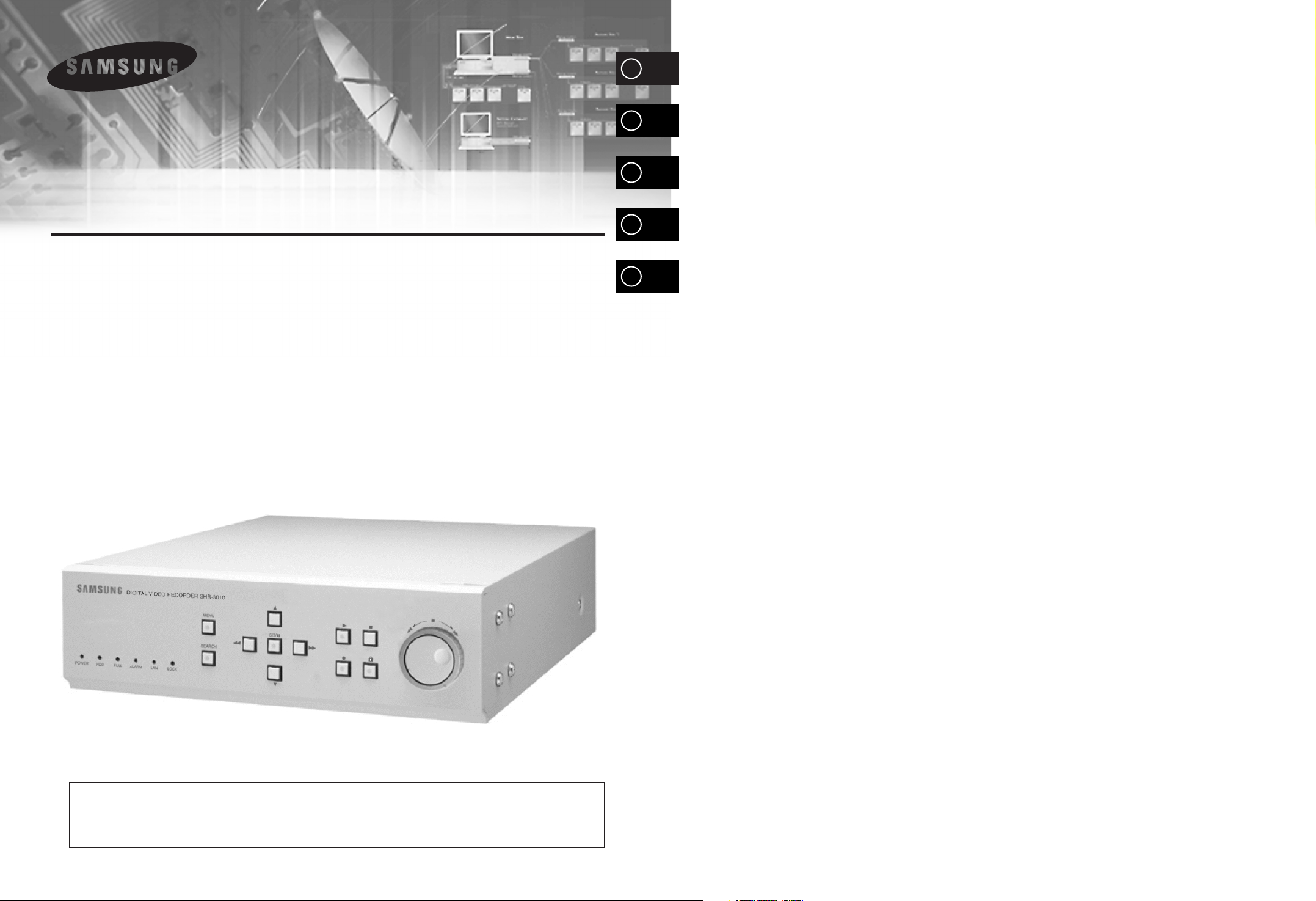
The Digital Video Recorder SHR-3010 is a Digital Time Lapse Recorder to utilize its
HDD as a recording media. How to use it is simple and therefore existing users of
Time Lapse VCR can also access to it since it is built with Jog/Shuttle. You can also
perform continuous recording on the HDD and directly view image recorded without
turning videotapes as in the existing Time Lapse VCR. SHR-3010 can record both
image and sound simultaneously, directly control the system from an external PC, and
back up data with an external SCSI HDD.
■ Upon booting the system, it recognizes automatically whether the incoming
signal is NTSC or PAL signal.
■ Adjusting screen quality in 4-steps
● Very High, High, Normal, Low
■ Variously changing numbers of recording fields per second.
● NTSC: 60 ~ 0.50 Fields/sec
● PAL: 50 ~ 0.50 Fields/sec
■ Simultaneous recording and regeneration
■ Reservation recording by using timers
■ Recording by alarm
■ Motion detection function and alarm occurrence or recording available in
motion detection
■ Multiplexer link
■ Various regeneration speed
● Frame Advance by Jog
● 1/5, 1/2, 1, 2, 5, 10, 20 baud rate (forward, backward)
■ Convenient retrieval function
● Date & Time Search, Alarm Event Search, Record Event Search
■ Convenient operation by using Jog/Shttle
■ Remote monitoring and control via LAN
● Network Interface: Ethernet (10/100BaseT)
● Protocol: TCP/IP
● Web Server: Image capture and remote monitoring through a Viewer Program installed at
PC
■ Automatic booting of system in power failure recovery during recording mode,
and starting of recording
■ Remote control by series communication
● RS232 1 port
● RS485 2 ports (connection of up to 32 sets)
●
Camera PAN/TILT/ZOOM Control of LAN VIEWER PROGRAM via Controlling RS-485
■ The recorded state and remnant hard disk space are displayed as bars on the
screen and especially in the play mode, the part currently being played of the
total hard disk capacity is displayed in the bar.
■ You can record video and audio at the same time.
■ Besides English, multi-language support provides German, French, Spanish,
and Italian.
■ You can back up data with SCSI.
■ You can control the camera and select channels with the Remote Viewer
Program. (For SAMSUNG model only :SCC-641, 643 Camera, SCC-421 Series
(4201, 4203, 4301, 4303) Camera, SDM-160 Multiplexer)
GB
Page 6
No Name Function
DOWN ( )
SET/STILL
( )
RIGHT ( )
PLAY ( )
RECORD ( ● )
REC LOCK( )
STOP ( ■ )
JOG/SHUTTLE
( / )
Used when moving cursor to the lower item of menu or
reducing values in setting-up details of menu.
Used when temporarily stopping during play or desiring to see
still screen. Plays a role as Enter in menu setup.
Used when fast forwarding during play of recorded image or
desiring to see still screens sequentially, or changing or editing
the left settings in setting-up details of menu.
Plays recorded data.
Records current live image.
Prevents other keys from being entered during record.
Stops play or record.
Used when moving cursor in menu setup or changing values
in setting-up details of menu. In addition, used when viewing
frames one by one during temporary stop in data play mode or
changing play speed.
1-3 1-4
DIGITAL VIDEO RECORDER
3
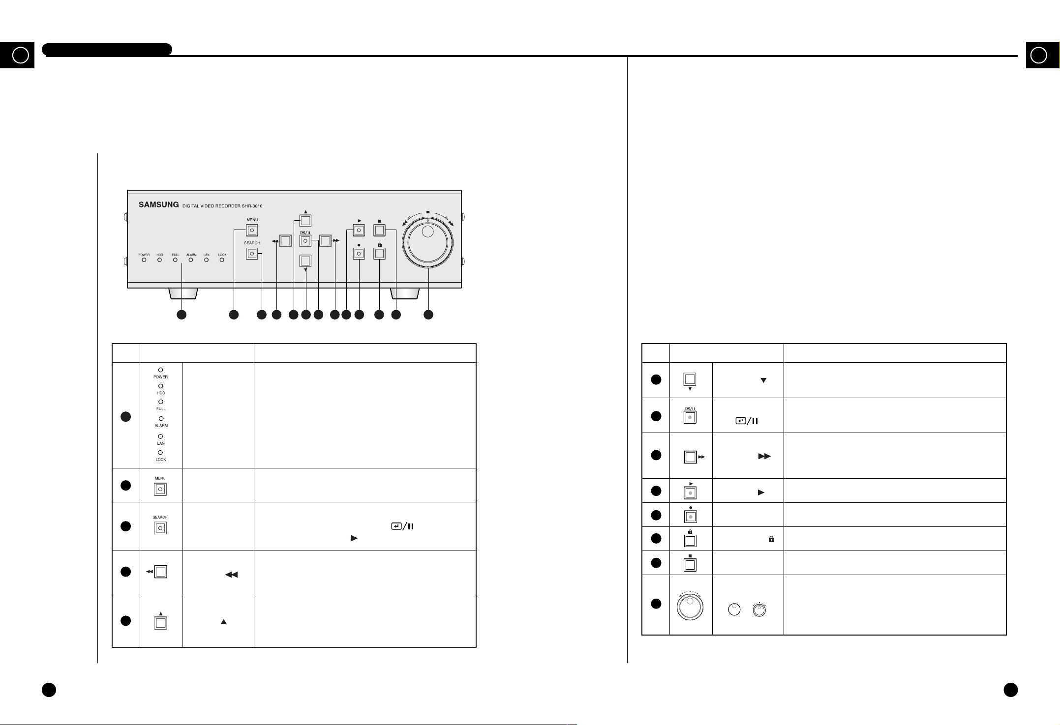
Name and Function of Each Part
GBGB
Front View
1 2 93 7 8 10 11 13124 5 6
No Name Function
STATUS
DISPLAY LED
Displays system status.
●
POWER : Checks power On.
●
HDD : Checks normal access to HDD.
●
FULL : Check if the hard disk is full.
●
ALARM : Check Alarm turns operates.
●
LAN : Checks LAN normally operates.
●
LOCK : Checks Recording Lock function
operates.
Used when displaying menu for setting-up systems or
entering from the sub menu to the top menu.
Displays recorded data lists. You can play it if selecting
each of them, pressing SET/STILL( ) button and
then pressing the PLAY( ) button.
Used when desiring to rewind during play of recorded image
or see still screen in reverse, or changing or editing the left
settings in setting-up details of menu.
Used for rewinding during play of recorded image or see
still screen in reverse or changing or editing the left
settings in setting-up details of menu.
SEARCH
MENU
LEFT ( )
UP ( )
1
2
3
4
5
6
7
8
9
10
11
12
13
Page 7
GB
1-6
GB
1-5
DIGITAL VIDEO RECORDER
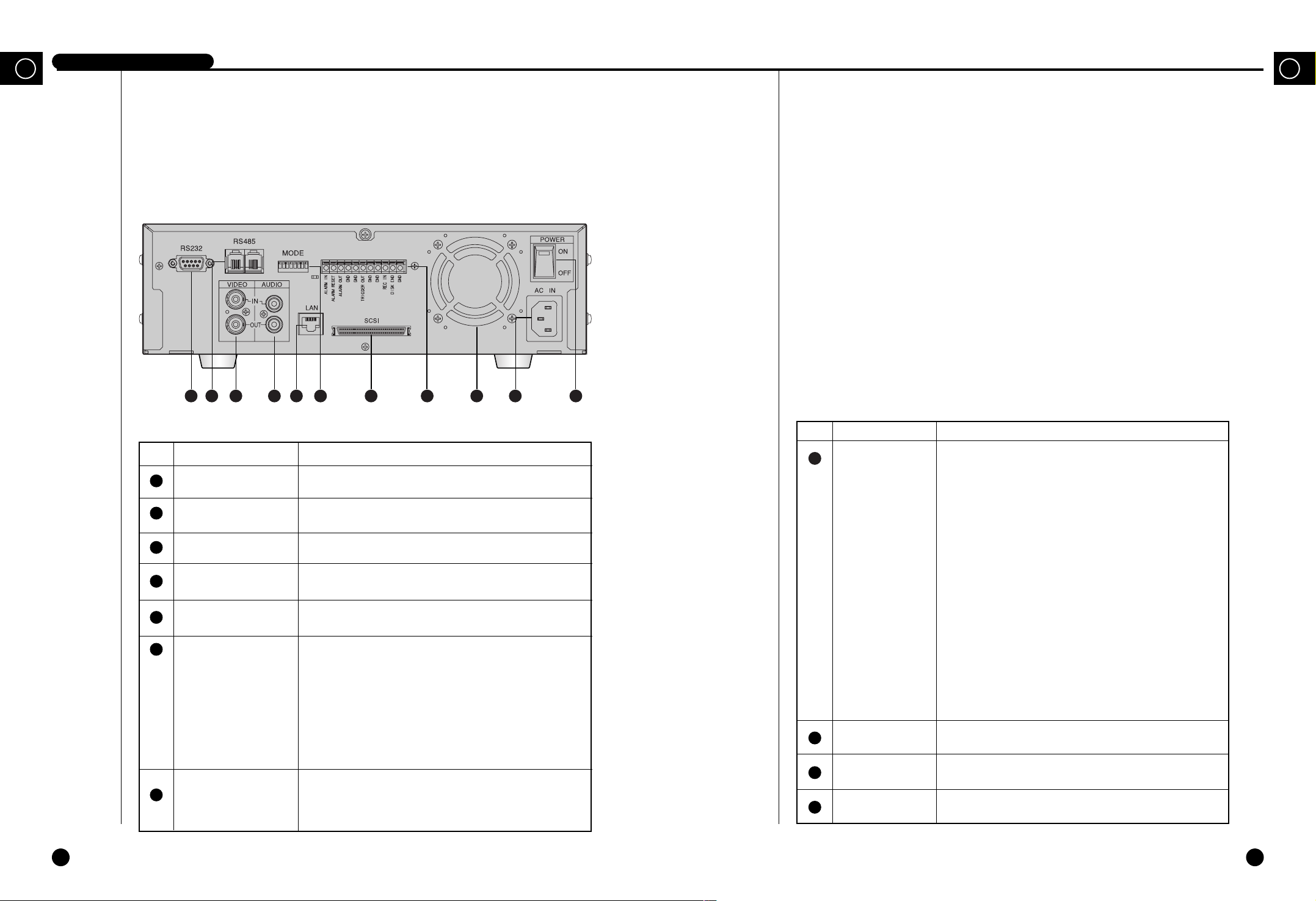
Rear View
1
2
3
4
5
No Name Function
EXTERNAL I/O
PORT
FAN
AC IN
POWER
●
ALARM IN: In the N.C. (Normally Closed) mode, the system
recognizes an alarm when a High (5V) signal is input for over
0.5 seconds. In the N.O. (Normally Open) mode, the system
recognizes an alarm when a Low (0V) signal is input for over
0.5 seconds. (Please refer to “➁ ALARM DETECT TYPE”
on p. 3-18.)
●
ALARM RESET: The alarm mode is cleared when a Low (0V)
signal is input for over 0.5 seconds.
●
ALARM OUT: A High (5V) signal is output during alarm
recording.
●
TRIGGER OUT: This signal is for switching the recording
output screen of the Multiplexer.
●
REC IN: The system begins recording when a Low (0V) signal
is input for over 0.5 seconds.
●
DISK END: If the DISK END MODE of the RECORD
MODE SETUP is set to STOP, a Low (0V) signal is output for
about 1 second when the HDD becomes full during recording.
(Please refer to “➃ DISK END MODE” on p. 3-16.)
Fan
Connects power cable.
Power On/Off button.
8
9
10
11
1 2 3 4 7 95 108 116
No Name Function
RS232 PORT
RS485 PORT
VIDEO IN/OUT
AUDIO IN/OUT
LAN
MODE
SCSI
Serial Port for remote control.
Serial Port for remote control.
Composite image signal I/O terminal (BNC Style Connector).
Audio Signal Input/Output Jacks (RCA Jacks).
LAN Cable Connection Terminal.
It is the DIP switch to set System ID, Direct Communication,
Termination, etc.
●
1~5 : System ID.
●
6 : Not Use.
●
7 : Termination On/Off (Of all the directly connected
systems, it sets the last system as On).
●
8 : Not Use.
SCSI Connector for Data Backup
6
7
Page 8
Caution
Caution
The above contents can be changed without notice in order to improve the
performance or function of the product.
1-7
1-8
DIGITAL VIDEO RECORDER
4
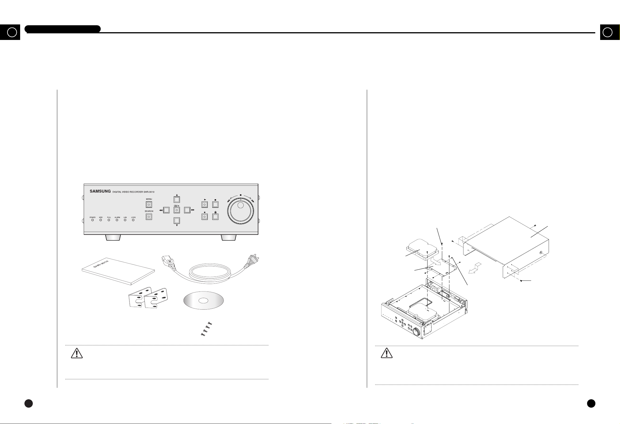
Unpacking
GBGB
5
HDD Addition
When purchasing product, first remove packing and put it on a flat floor or at a place to use it.
Then, ensure all following contents are included:
◗ Main body
◗ User’s Manual
◗ 1 power cord
◗ 2 Rack Mount Adapter
◗ SCREW-MACHINE (PH, UNC6-32, L4.2, WHT) x 4
◗ Remote Viewer Program Installation CD
Mounting HDD
1. Unfasten the SCREW-SPECIAL (BWH, M4, L8, WHT) 11 EA attached to the left, right,
and rear of the product, and then remove the CABINET-TOP from the product.
2. Unfasten the SCREW-TAPTITE (BH, M3, L6 WHT) 3 EA to remove the HDD from the
BRACKET-HDD as shown in the picture.
3. Attach the HDD to the BRACKET-HDD as shown in the picture, and fasten the SCREW-
MACHINE (PH, UNC6-32 L4, WHT) 4 EA supplied as ACCESSORY.
4. Place the HDD with the BRACKET-HDD inside the product, and fasten the SCREW-
TAPTITE (BH, M3, L6 WHT) 3 EA.
5. Connect the Power Supply Cable and the AT-Bus Interface Cable. (Refer to “Cable
Connection” on page 1-10.)
6. Put the CABINET-TOP back on, and fasten the SCREW-SPECIAL (BWH, M4, L8,
WHT).
Caution
Caution
Basically, a product with two HDDs has two HDDs attached to the HDD brackets
as it is introduced to the market. And a product with a single HDD is supplied
with an extra HDD bracket aside from the HDD bracket for attaching the HDD.
HDD
BRACKET- HDD
SCREW-MACHINE(PH, UNC6-32, L4, 2, WHT)
SCREW-SPECIAL(BWH, M4, L8, WHT)
SCREW-TAPTITE(BH, M3, L6, WHT)
CABINET-TOP
Page 9
GB
1-10
GB
1-9
DIGITAL VIDEO RECORDER
Mode setup and cable connection
Set a HDD mode and connect cables after mounting the HDD to product.
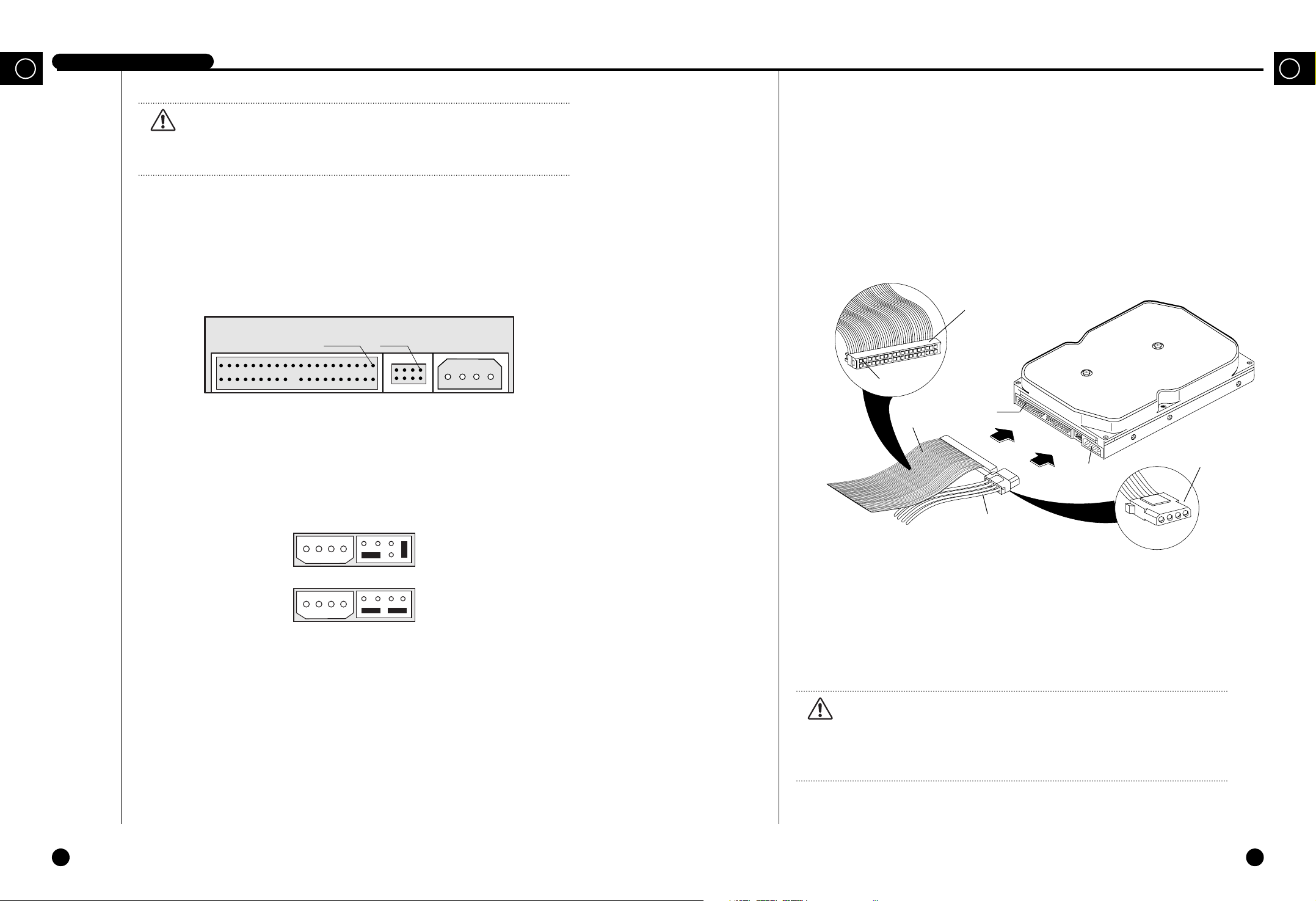
Below is shown drawing of Power Connector and AT-Bus Interface Connector and
Configuration Jumper Block of HDD.
Setting of HDD mode is performed in a Configuration Jumper Block.
When mounting two hard disk drives on the product, one should be set in the Master Mode
and the other in the Slave Mode. Basically, since the hard disk drive mounted on the product
is in the Master Mode, when mounting a new hard disk drive it can be set in the Slave
Mode. For example, mode is set as follows in case of Samsung Spinpoint V40 HDD:
40-Pin AT-Bus
Interface Connector
8-Pin Configuration
Jumper Block
Pin 1 Pin 1
4 3 2 1
4-Pin DC
Power Connector
Master Mode
Slave Mode
AT-Bus Interface Cable and Power Supply Cable are connected to AT-Bus Interface
Connector are connected by referring to following drawing to ensure the HDD mounted on
product can properly operate.
If successfully mounting the HDD on the product and then booting the system, the system
recognizes that a new HDD is mounted and starts to operate after formatting the first HDD.
Caution
Caution
We recommend Samsung Electronics’ Spinpoint V40 SV4002H or SV8004H as a
HDD for this product. When installing an additional HDD, please be sure to
inquire at the store where you purchased this product.
AT-Bus
Interface
Connector
AT-Bus
Interface
Cable
Power Supply
Cable
(4Pin)
DC Power
Connector
40Pin
Header
40Pin
Bevel
Caution
Caution
Please be sure to turn the system off before you replace or add the HDD. If not,
the HDD may poorly operate or the life may be reduced.
Page 10

II. Connection with
Other Devices
2
GB
Page 11
2-2
GB
2-1
1
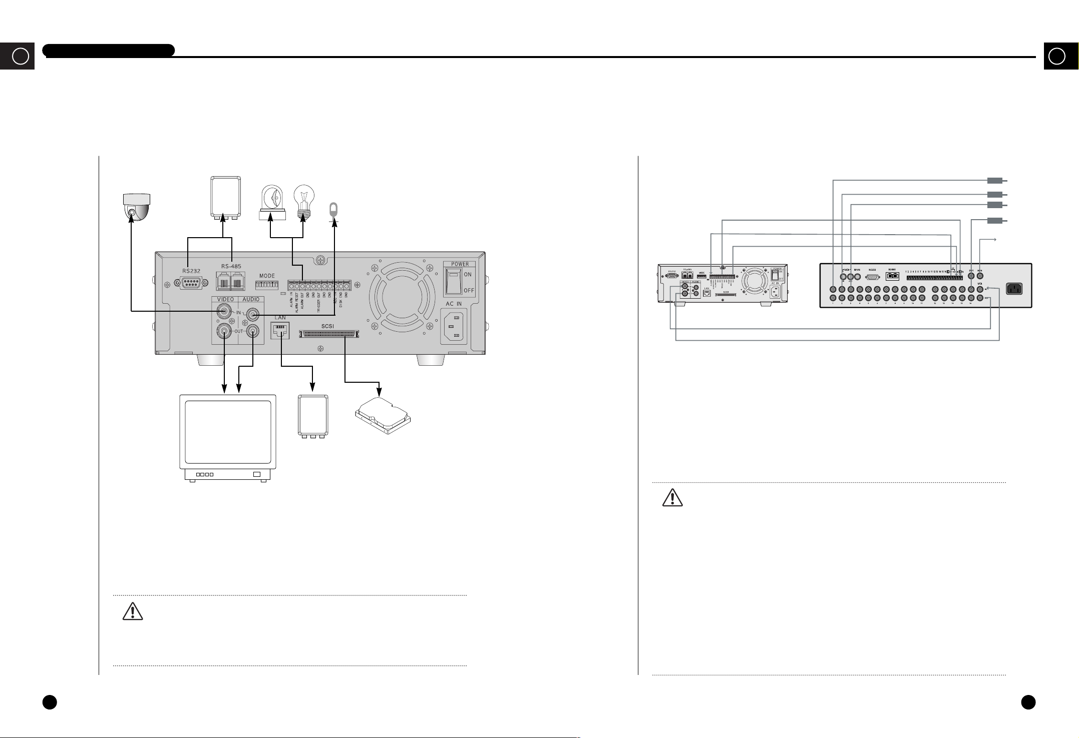
Connection to External Devices
2
Connection with Multiplexer
(e.g. connection to SDM-160)
DIGITAL VIDEO RECORDER
CAMERA RX SIREN LIGHT
VIDEO OUT
(NTSC/PAL MONITOR)
LAN
AUDIO OUT
SHR-3010 VIDEO RECORDER
■ This unit can be connected to external devices such as a camera for video signal input, a
microphone for audio signal input, and an NTSC or PAL monitor for video and audio signal
output.
■ It can be connected to external devices such as an alarm according to the user’s request.
■ It can be connected to a PC through a LAN or Serial connection for remote control.
■ Your may back up data with a backup device using SCSI for the purpose of data backup.
Caution
Caution
– A CRT monitor capable of displaying an NTSC or PAL video signal must be used
with this unit. An ordinary computer monitor cannot be used.
– The backup device of this equipment is applicable only to SCSI HDDs.
AC IN
CAMERA
1
2
3
.
.
.
16
MONITOR
OUT
TRIGGER OUT
ALARM IN
GND
SHR-3010 VIDEO RECORDER
SDM-160 DIGITAL MULTIPLEXER
VIDEO IN
VIDEO OUT
■ SDM-160 is a Multiplexer for NTSC, and SDM-160P is a Multiplexer for PAL.
■ For details on the functions of SDM-160, please refer to the user’s guide of SDM-160.
■ Connect this unit’s video signal input jack to the video signal output jack of SDM-160 and
connect this unit’s video signal output jack to the video signal input jack of SDM-160.
■ Connect the alarm output jack (ALARM OUT) of SDM-160 to this unit’s alarm input jack
(ALARM IN), and connect the VTI jack of SDM-160 to this unit’s trigger output jack
(TRIGGER OUT).
■ Connect both GND terminals together.
■ You do not have to connect the alarm out (ALARM OUT) and alarm reset (ALARM
RESET) terminals of this unit.
Caution
Caution
- Be sure to connect the trigger output terminal (TRIGGER OUT) of this unit to the
Multiplexer. Otherwise, a normal recording cannot be made.
(For the connection method, please refer to the user’s guide for the Multiplexer
you want to use.)
- If the system’s recording field rate is set to 0.50 ~ 15 FPS (Fields Per Second) for
the input NTSC video signal and to 0.50 ~ 12.5 FPS for the input PAL video
signal, be sure to set the Multiplexer in such a way that the recording output
screen is switched by the Trigger Pulse. (For settings related to the recording
field rate, please refer to “
##
PICTURE RATE” on p. 3-15.)
- If the system’s recording filed rate is set to 30 FPS for the input NTSC video
signal and to 25 FPS for the input PAL video signal, a half of the input video
channels may not be recorded depending on the type of Multiplexer. In this case,
set the recording field rate to 60 FPS for NTSC and to 50 FPS for PAL.
GB
MICROPHONE
Page 12

2-3 2-4
DIGITAL VIDEO RECORDER
3
System Connection for Alarm Recording
GBGB
4
Connection with PC for Use
<Rear Side Connection Terminal of SHR-3010>
<Outside Product>
ALARM IN
ALARM RESET
ALARM OUT
TRIGGER OUT
GND
■ Alarm recording is a function for recording the input video when an alarm signal is input
while a device with alarm output is connected to this unit.
■ Connect to the corresponding terminals, as the numbers may be different for external
devices.
■ For external devices, if the alarm input (ALARM INPUT) and alarm cancel (ALARM
CANCEL) are not available, you can leave them unconnected.
GND
TRIGGER IN
ALARM IN
ALARM CANCEL
ALARM OUT
1
1
2
3
6
1
1
2
3
4
5
2 3 4 5 6 7 8 9 10 11 1 2 3 4 5
Connection with RS-232C
A. Communication Method
● Data Code: ASCII Code
● Protocol: 8 bit Data, 1 Stop bit, None Parity
● Transmission speed: 4800, 9600, 19200, 38400 bps
B. RS-232C terminal (D-SUB 9 Pin) and Pin specifications
51
69
Pin No Pin Specifications
2 TXD (Transmitted Data)
3 RXD (Received Data)
5 SG (Signal Ground)
1, 4, 6~9 NO Connection
Page 13

GB
2-6
GB
2-5
DIGITAL VIDEO RECORDER
Connection with RS-485
Remote control is allowed through connection with RS-485 (up to 1.2km).
A. Communication method
● Data transmission method: Start-Stop Synchronized Serial Interface
● Protocol: 8 bit Data, 1 Stop bit, None Parity
● Transmission speed: 4800, 9600, 19200, 38400 bpss
B. RS-485 terminal and Pin specifications
C. Data Format (Samsung Protocol)
DATA +
DATA -
9 Byte Fixed
( ) : Byte numbers
Start Code (A0H)
(1)
Data Byte Type Contents Remarks
Byte 1 Start Code 0xA0 Start of Data Packet
Byte 2 Sender Addr. Transmission Address Source Range (0x00 ~ 0xFF)
Byte 3 Target Addr. Reception Address Destination Range (0x00 ~ 0xFF)
Byte 4 Only Image Recorder Command 0x0A
Byte 5 Key Function Range (0x01 ~ 0xFF)
Byte 6 Command 0xFF 0xFF
Byte 7 0xFF 0xFF
Byte 8 0xFF 0xFF
Byte 9 Check Sum Lower byte of (0xFFFF - (values adding Byte 2 ~ Byte 8))
Start Addr.
(1)
Target Addr.
(1)
Command
(5)
Check Sum
(1)
D. Code value by key
Function Byte 1 Byte 2 Byte 3 Byte 4 Byte 5 Byte 6, 7, 8 Byte 9
Response
(Byte 5)
[SET COMMAND]
MENU 0xA0 Src.Addr Dest.Addr. 0x0A 0x01 0xFF Check Sum 0x01
SEARCH 0xA0 Src.Addr Dest.Addr. 0x0A 0x02 0xFF Check Sum 0x02
SET/STILL 0xA0 Src.Addr Dest.Addr. 0x0A 0x03 0xFF Check Sum 0x03
UP 0xA0 Src.Addr Dest.Addr. 0x0A 0x04 0xFF Check Sum 0x04
DOWN 0xA0 Src.Addr Dest.Addr. 0x0A 0x05 0xFF Check Sum 0x05
LEFT 0xA0 Src.Addr Dest.Addr. 0x0A 0x06 0xFF Check Sum 0x06
RIGHT 0xA0 Src.Addr Dest.Addr. 0x0A 0x07 0xFF Check Sum 0x07
PLAY 0xA0 Src.Addr Dest.Addr. 0x0A 0x08 0xFF Check Sum 0x08
STOP 0xA0 Src.Addr Dest.Addr. 0x0A 0x09 0xFF Check Sum 0x09
RECORD 0xA0 Src.Addr Dest.Addr. 0x0A 0x0A 0xFF Check Sum 0x0A
REC LOCK 0xA0 Src.Addr Dest.Addr. 0x0A 0x0B 0xFF Check Sum 0x0B
F.Shuttle 1 0xA0 Src.Addr Dest.Addr. 0x0A 0x0C 0xFF Check Sum 0x0C
F.Shuttle 2 0xA0 Src.Addr Dest.Addr. 0x0A 0x0D 0xFF Check Sum 0x0D
F.Shuttle 3 0xA0 Src.Addr Dest.Addr. 0x0A 0x0E 0xFF Check Sum 0x0E
F.Shuttle 4 0xA0 Src.Addr Dest.Addr. 0x0A 0x0F 0xFF Check Sum 0x0F
F.Shuttle 5 0xA0 Src.Addr Dest.Addr. 0x0A 0x10 0xFF Check Sum 0x10
F.Shuttle 6 0xA0 Src.Addr Dest.Addr. 0x0A 0x11 0xFF Check Sum 0x11
F.Shuttle 7 0xA0 Src.Addr Dest.Addr. 0x0A 0x12 0xFF Check Sum 0x12
F.Shuttle 8 0xA0 Src.Addr Dest.Addr. 0x0A 0x13 0xFF Check Sum 0x13
R.Shuttle 1 0xA0 Src.Addr Dest.Addr. 0x0A 0x14 0xFF Check Sum 0x14
R.Shuttle 2 0xA0 Src.Addr Dest.Addr. 0x0A 0x15 0xFF Check Sum 0x15
R.Shuttle 3 0xA0 Src.Addr Dest.Addr. 0x0A 0x16 0xFF Check Sum 0x16
R.Shuttle 4 0xA0 Src.Addr Dest.Addr. 0x0A 0x17 0xFF Check Sum 0x17
R.Shuttle 5 0xA0 Src.Addr Dest.Addr. 0x0A 0x18 0xFF Check Sum 0x18
R.Shuttle 6 0xA0 Src.Addr Dest.Addr. 0x0A 0x19 0xFF Check Sum 0x19
R.Shuttle 7 0xA0 Src.Addr Dest.Addr. 0x0A 0x1A 0xFF Check Sum 0x1A
R.Shuttle 8 0xA0 Src.Addr Dest.Addr. 0x0A 0x1B 0xFF Check Sum 0x1B
R.JOG 0xA0 Src.Addr Dest.Addr. 0x0A 0x1C 0xFF Check Sum 0x1C
F.JOG 0xA0 Src.Addr Dest.Addr. 0x0A 0x1D 0xFF Check Sum 0x1D
E. Others
● Above data format and transmission speed may be changed depending on future
development conditions.
● PC operates as Master, and Target Set as Slave in transmission/reception of data.
● No status other than Set Key Function should be received. Provided, however, that con
tents recorded in a set should be always received for alarm function
(Some delay can be happen due to communication speed).
Page 14

III. Basic Method
to use
3GB3-2
Page 15

GB
3-1
DIGITAL VIDEO RECORDER
1
Booting the System
Power On
There is a power switch on the upper right hand side behind the system. Pull the power
switch up to boot the system. Then, the LED on front of the system is turned on, a blue
screen with the following message will appear and the system is booted.
When you turn the system on, a blue screen appears and starts searching HDD. The message
in the screen tells any HDD exists in the main body. The main body can contain 2 HDDs,
one is installed properly but the other is not yet installed.
If the second HDD is installed, the message, ‘HDD DETECTED =>2 OK’ will be displayed.
When booting is finished, the following Live screen will appear.
Recognizing incoming video signal
SHR-3010 system can automatically recognize whether the video signal connected at the input port
is NTSC or PAL signal upon booting the system.
When you turn the system on, it will recognize if the image signal is NTSC or PAL automatically to
set itself to the signal.
If the system power is turned on without connecting video signals to the input port, the
system remembers the last signal and the system is configured accordingly. For example, if the past
video signal connected to the input port was an NTSC signal, the system is configured to fit NTSC
signals and for PAL, the same process is applied to fit PAL signals. However, if suddenly a type of
video signal that is different from the video signal currently connected to the input port is connected,
the screen will malfunction. In short, this is a case where PAL signal is connected to a system
configured to satisfy NTSC signals or the other way around. In these cases, system power should be
turned off, the new signal connected and then the system turned back on in order to be configured to
recognize the new signal.
If you power on the system without attaching the hard disk drive, you will get an error message
indicating that no hard disk drive was found.
GB
HDD DETECTED => 1 OK
HDD DETECTED => 2 NOT EXIST
2001-09-15 17:14:55
HDD DETECTED => 1 NOT EXIST
HDD DETECTED => 2 NOT EXIST
1
Page 16

3-4
GB
3-3
DIGITAL VIDEO RECORDER
GB
Power Off
Push the power switch down in order to turn off the system.
When the system power is turned off during recording, recording will be resumed next time
the system power is turned on and booting is complete.
Caution
Caution
Wait at least 3 seconds after turning off the system power before turning it back on.
Otherwise, the system may malfunction.
And the system will automatically keep on searching for a hard disk drive as shown below.
If you attach a hard disk drive at this time, the system will recognize the hard disk drive, the
boot process will end, and a live screen will appear.
2
Basic Screen Viewing
If system is in the recording state icon will blink. However, it does not blink in the
Live Screen state.
If the system is in the recording state due to alarm, icon appears. In this state,
icon continually blinks.
If the system is in the recording state due to Motion Detection, icon appears.
In this state, icon continually blinks.
If the system is in the recording state due to the timer, icon appears.
If the system in the recording lock state, icon appears.
It occurs when the system is connected to remote viewer program through the LAN.
If the system is in a state of recording, 1 icon will blink. However, it does not blink in
the Live Screen state. It shows in which hard disk drive the video data is stored.
If there is only one hard disk drive installed in the system, there is always one icon.
But if there are two hard disk drives installed, data is stored in the second hard disk
after the first hard disk is full and then, the icon changes as in 2 .
The SCSI HDD was detected through the SCSI connector behind the main body.
The upper pointer shows the relative location of the recorded data being stored inside
the hard disk and the lower pointer shows the relative location of the data currently
being played back. The following pointer will be hidden in the general live screen and
recording screen.
You can change the above system status display position. The user will mark the position in the
top left and right corner. (Select LEFT or RIGHT in STATUS POSITION of the
CLOCK/DISPLAY MODE SET UP menu. Please refer to Page 3-14 for the details)
Viewing Full Screen
Here comes the description of all the icons and status in the screen.
1
2001-08-22 18:19:12
√X2 2001-09-24 00:23:44
SYSTEM UNSTABLE OR HDD NOT EXIST
RESET HDD DEVICE(S)
>TRY TO FIND HDD
>HDD NOT FOUND
Page 17

3-6
GB
3-5
DIGITAL VIDEO RECORDER
GB
It shows the current date and time as configured by the system.
You can change the display position of date and time. You shall designate the position
in the top right or left corner by yourself. (Just choose LEFT or RIGHT in the
CLOCK/DISPLAY MODE SETUP menu. Please refer to Page 3-14 for the details)
If the system is in the playback mode, icon appears. And if the system is in the
pause state, it changes to this icon
❙❙
. In addition, stored data can be played back at
various speeds; when played in the forward direction at speeds other than the normal
speed, the speed is shown on the right side of the icon and if it is played in the
reverse direction at speeds other than the normal speed, icon appears and the right side
of this icon shows the speed. Possible speeds in the system for forward and reverse
directions are 1/5, 1/2, 1, 2, 5, 10, 20 times normal speed.
It shows the recorded date and time of the data currently being played back.
You can change the recording date and time display position. The user will mark the
position in the bottom left and right corner. (Select LEFT or RIGHT in TIME MARK
POSITION of the RECORD MODE SET UP menu. Please refer to Page 3-15 for the
details.)
2001-08-22 18:19:12
2001-09-24 00:23:44
X2
Live Screen Viewing
The normal Live screen looks like this.
2001-09-15 07:14:55
If system is in the recording state icon will blink. However, it does not blink in the
Live Screen state.
If the system is in a state of recording, 1 icon will blink. However, it does not blink
in the Live Screen state. It shows in which hard disk drive the video data is stored. If
there is only one hard disk drive installed in the system, there is always one icon. But
if there are two hard disk drives installed, data is stored in the second hard disk after
the first hard disk is full and then, the icon changes as in 2 .
It shows the relative location of the recorded data inside the hard disk.
It shows the current date and time as configured by the system.
1
2001-09-15 07:14:55
1
Page 18

3-8
GB
3-7
DIGITAL VIDEO RECORDER
GB
Playback screen Viewing
The normal Playback screen looks like this.
Viewing Screen during recording
The normal recording screen looks like this.
2001-08-22 18:19:12
If the system is executing the recording function, icon blinks.
If the system is in the recording state due to alarm, icon appears. In this state,
icon continually blinks.
If the system is in the recording state due to Motion Detection, icon appears.
In this state, icon continually blinks.
If the system is in the recording state due to the timer, icon appears.
If the system in the recording lock state, icon appears.
It occurs when the system is connected to remote viewer program through the LAN.
2001-09-24 00:23:44
The upper pointer shows the relative location of the recorded data being stored inside
the hard disk and the lower pointer shows the relative location of the data currently
being played back.
If the system is in the playback mode, icon appears. And if the system is in the
pause state, it changes to this icon
❙❙
. In addition, stored data can be played back at
various speeds; when played in the forward direction at speeds other than the normal
speed, the speed is shown on the right side of the icon and if it is played in the
reverse direction at speeds other than the normal speed, icon appears and the right side
of this icon shows the speed. Possible speeds in the system for forward and reverse
directions are 1/5, 1/2, 1, 2, 5, 10, 20 times normal speed.
It shows the recorded date and time of the data currently being played back.
2001-09-24 00:23:44
1
Page 19

3-10
GB
3-9
DIGITAL VIDEO RECORDER
GB
Change of Settings
① Move to desired menu item by using an UP( ) or a DOWN( ) button.
➁ You can change settings by pressing the SET/STILL( ) button.
➂ Press the UP( ) or DOWN( ) button in order to change settings.
➃ Settings will be changed if pressing the SET/STILL( ) button after selecting
desired
settings.
Move to Parent Menu or Menu End
Press the MENU button to move to the parent menu from the lower mode or end the menu.
Note
Note
In general, you can use the UP( ) or DOWN( ) button to change the setting, but
you can also use the JOG( ).
Menu Enter
Press a MENU button. Then, following screen appears.
Menu Move
Move to desired menu item by using an UP( ) or a DOWN( ) button. In this case, a
highlighted cursor is displayed in the selected item. The sub menu item is displayed if
pressing a SET/STILL( ) button. Selections appear in the left side and settings for
selected matters appear in the right side.
3
Menu View
Note
Note
You can go into the menu only when the system is in the Live screen mode. If the
system is in the recording mode or playback mode, you cannot go into the menu.
To go into the menu, first stop the recording or playback.
Note
Note
In general, you can use the UP( ) or DOWN( ) button to move to the desired
menu item, but you can also use the JOG( ). Turn the JOG( ) counterclockwise
to move the cursor downward, turn it clockwise to move the cursor upward.
MAIN MENU
CLOCK/DISPLAY MODE SETUP
RECORD MODE SETUP
ALARM RECORD SETUP
TIMER RECORD SETUP
SYSTEM SETUP
COMMUNICATION SETUP
SYSTEM INFORMATION
BACKUP SETUP
Page 20

3-12
GB
3-11
DIGITAL VIDEO RECORDER
GB
➃ Similarly, press the UP( ) or DOWN( ) button so current minute is displayed.
Then if pressing the LEFT( ) or RIGHT( ) button, the cursor is changed so hour or
second is changed. For example, press the RIGHT( ) button to change seconds and
setup by pressing the UP( ) or DOWN( ) button so current second is displayed.
➄ The cursor is changed as follows if pressing the SET/STILL( ) button after setting
all hours. You may change other settings by pressing the LEFT( ) or RIGHT( )
button.
Example of menu setting (in case of changing time)
① Press the MENU button and then press the SET/STILL( ) button when the cursor
points out the CLOCK/DISPLAY MODE SETUP. Then following screen appears.
➁ Press the DOWN( ) button so the cursor points out TIME.
Then if pressing the SET/STILL( ) button, the cursor is changed so hour may be
changed.
➂ Press the UP( ) or DOWN( ) button so current time (hour) is displayed.
Then if pressing the RIGHT( ) button, the cursor is changed so minute may be
changed.
CLOCK/DISPLAY MODE SETUP
DATE 2001-12-07
TIME 12:00:00
DATE DISPLAY TYPE YYYY-MM-DD
DATE & TIME DISPLAY ON
DATE & TIME POSITION RIGHT
STATUS DISPLAY ON
STATUS POSITION LEFT
CLOCK/DISPLAY MODE SETUP
DATE 2001-12-07
TIME 12:00:00
DATE DISPLAY TYPE YYYY-MM-DD
DATE & TIME DISPLAY ON
DATE & TIME POSITION RIGHT
STATUS DISPLAY ON
STATUS POSITION LEFT
CLOCK/DISPLAY MODE SETUP
DATE 2001-12-07
TIME 09:00:00
DATE DISPLAY TYPE YYYY-MM-DD
DATE & TIME DISPLAY ON
DATE & TIME POSITION RIGHT
STATUS DISPLAY ON
STATUS POSITION LEFT
CLOCK/DISPLAY MODE SETUP
DATE 2001-12-07
TIME 09:34:00
DATE DISPLAY TYPE YYYY-MM-DD
DATE & TIME DISPLAY ON
DATE & TIME POSITION RIGHT
STATUS DISPLAY ON
STATUS POSITION LEFT
CLOCK/DISPLAY MODE SETUP
DATE 2001-12-07
TIME 12:00:00
DATE DISPLAY TYPE YYYY-MM-DD
DATE & TIME DISPLAY ON
DATE & TIME POSITION RIGHT
STATUS DISPLAY ON
STATUS POSITION LEFT
Page 21

3-14
GB
3-13
DIGITAL VIDEO RECORDER
GB
4
Setting of Date, Time and Screen
The following illustrates the intial setting of the CLOCK/DISPLAY MODE SETUP menu.
① DATE
Set the current date.
② TIME
Time can be entered in the form of 24 hours.
➂ DATE DISPLAY TYPE
There are 3 date forms to be displayed. You can set in a convenient manner to see.
[YYYY-MM-DD/DD-MM-YYYY/MM-DD-YYYY]
➃ DATE & TIME DISPLAY
Set to ON to display the date and time on the screen, or set to OFF to not display them.
[ON/OFF]
➄ DATE & TIME POSITION
Set the location on the screen where the date and time will be displayed. Set to LEFT to
display it on the top left of the screen, or set to RIGHT to display it on the top right of the
screen. [LEFT/RIGHT]
➅ STATUS DISPLAY
Set to ON to display the system status, such as recording, system lock, to which HDD the
data is being stored, remaining HDD capacity, and playback information when playing the
recorded video; or set to OFF to not display them. [ON/OFF]
➆ STATUS POSITION
Set the location on the screen where the system status will be displayed. Set to LEFT to
display it on the top left of the screen, or set to RIGHT to display it on the top right of the
screen. [LEFT/RIGHT]
Caution
Caution
Be sure to set the date and time to the current date and time.
① CLOCK/DISPLAY MODE SETUP ➄ SYSTEM SETUP
② RECORD MODE SETUP ➅ COMMUNICATION SETUP
➂ ALARM RECORD SETUP ➆ SYSTEM INFORMATION
➃ TIMER RECORD SETUP ⑧ BACKUP SETUP
Each menu item
Caution
Caution
Upon shipment from the factory, the values of the menu are set as follows.
CLOCK/DISPLAY MODE SETUP
DATE 2002-01-01
TIME 12:00:00
DATE DISPLAY TYPE YYYY-MM-DD
DATE & TIME DISPLAY ON
DATE & TIME POSITION RIGHT
STATUS DISPLAY ON
STATUS POSITION LEFT
SYSTEM SETUP
PASSWORD ****
PASSWORD LOCK OFF
HDD ERASE OFF
FACTORY RESET OFF
MENU SCREEN DARK GRAY
LANGUAGE ENGLISH
COMMUNICATION SETUP
BAUD RATE 115,200
NETWORK ACCESS ON
IP ADDRESS 0. 0. 0. 0
GATEWAY 0. 0. 0. 0
SUBNET MASK 0. 0. 0. 0
NETWORK USER ID ****
NETWORK USER PWD ****
BACKUP SETUP
TIME RANGE
FROM RECORD EVENT LIST
FROM ALARM EVENT LIST
SEARCH & PLAY OF BACKUP
OVERWRITE OFF
SCSI ERASE OFF
SYSTEM INFORMATION
HDD1 HDD2
CAPACITY(GB) 80.00 NO
OVERWRITE(#) 00000 NO
VERSION SHR301 3.11
MAC ADDRESS ff-ff-ff-ff-ff-ff
RECORD MODE SETUP
AUDIO RECORD OFF
PICTURE QUALITY NORMAL
PICTURE RATE 30.00FPS
DISK END MODE STOP
DISK END BUZZER ON
RECORD TIME MARK ON
TIME MARK POSITION RIGHT
ALARM RECORD SETUP
ALARM ENABLE OFF
ALARM DETECT TYPE N.O.
ALARM BUZZER ON
MAIN ALARM TIME 10SECOND
PRE ALARM TIME LIMIT 2SECOND
POST ALARM TIME LIMIT OFF
MAIN ALARM PICTURE RATE 30.00FPS
MOTION DETECTION OFF
SET AREA & SENSITIVITY
TIMER RECORD SETUP
TIMER DAY START END FIELD RATE
OFF --- --:-- --:-- --.-OFF --- --:-- --:-- --.-OFF --- --:-- --:-- --.-OFF --- --:-- --:-- --.-OFF --- --:-- --:-- --.-OFF --- --:-- --:-- --.-OFF --- --:-- --:-- --.-OFF --- --:-- --:-- --.-OFF --- --:-- --:-- --.--
CLOCK/DISPLAY MODE SETUP
DATE 2002-01-01
TIME 12:00:00
DATE DISPLAY TYPE YYYY-MM-DD
DATE & TIME DISPLAY ON
DATE & TIME POSITION RIGHT
STATUS DISPLAY ON
STATUS POSITION LEFT
Page 22

3-16
GB
3-15
DIGITAL VIDEO RECORDER
GB
Note
Note
The following table shows how long it takes to fill the 40GB HDD with respect to each field
rate when the video signal is NTSC and PAL respectively.
(Recording time for each field rate may slightly vary depending on the type of input
video singal.)
➃
DISK END MODE
● If you select STOP, recording will stop when you consume the full HDD space.
● If you select CONTINUE, the new data will be recorded while overwriting the existing
data in the HDD from the oldest one. The relative positions where the recorded data are
being stored in the HDD will be indicated on the screen in a bar format. If the DISK
END MODE is set to STOP, in addition, the remaining HDD capacity will be indicated
in percentage (%). Also, if the DISK END MODE is set to STOP, HDD FREE SPACE
will be shown at the bottom of the menu, but if it is set to CONTINUE, it will not be
shown. [STOP/CONTINUE]
5
Record Setup
The following illustrates the intial setting of the RECORD MODE SETUP menu.
① AUDIO RECORD
Set to ON to record video and audio at the same time, or set to OFF to record video only.
Audio is input and recorded at 6.3 Kbps regardless of the recording field rate of the video
[ON/OFF].
② PICTURE QUALITY
Picture quality is divided into four levels. Set to VERY HIGH for the best picture quality,
or set to HIGH, NORMAL, or LOW in the descending order of qualty. The user can select
the desired quality. [VERY HIGH/HIGH/NORMAL/LOW]
➂ PICTURE RATE
Set the picture rate for the input video. If the input video signal is NTSC, a maximum of
60 FPS (Fields Per Second) can be recorded; if it is PAL, a maximum of 50 FPS can be
recorded.
1) NTSC
[60.00FPS/30.00FPS/15.00FPS/10.00FPS/7.50FPS/5.00FPS/2.50FPS/
1.00FPS/0.50FPS]
2) PAL
[50.00FPS/25.00FPS/12.50FPS/8.33FPS/6.25FPS/5.00FPS/2.50FPS/
1.00FPS/0.50FPS]
RECORD MODE SETUP
AUDIO RECORD OFF
PICTURE QUALITY NORMAL
PICTURE RATE 30.00FPS
DISK END MODE STOP
DISK END BUZZER ON
RECORD TIME MARK ON
TIME MARK POSITION RIGHT
Picture Rate
Time-Lapse Mode
VERY HIGH HIGH NORMAL LOW
60.00 FPS 11 H 15 H 20 H 26.0 H
30.00 FPS 22.0 H 30.0 H 40.0 H 52.0 H
15.00 FPS 33.0 H 60.0 H 80.0 H 104.0 H
10.00 FPS 44.0 H 90.0 H 120.0 H 156.0 H
NTSC
7.50 FPS 66.0 H 120.0 H 160.0 H 207.0 H
5.00 FPS 100.0 H 180.0 H 240.0 H 310.0 H
2.50 FPS 200.0 H 360.0 H 480.0 H 610.0 H
1.00 FPS 500.0 H 900.0 H 1200.0 H 1500.0 H
0.50 FPS 1000.0 H 1800.0 H 2400.0 H 3000.0 H
50.00 FPS 13.2 H 15.0 H 20.0 H 24.0 H
25.00 FPS 26.4 H 30.0 H 40.0 H 48.0 H
12.50 FPS 52.8 H 60.0 H 80.0 H 96.0 H
8.33 FPS 79.2 H 90.0 H 120.0 H 144.0 H
PAL
6.25 FPS 105.0 H 120.0 H 160.0 H 192.0 H
5.00 FPS 132.0 H 150.0 H 200.0 H 240.0 H
2.50 FPS 262.0 H 300.0 H 400.0 H 480.0 H
1.00 FPS 660.0 H 750.0 H 1000.0 H 1200.0 H
0.50 FPS 1320.0 H 1500.0 H 2000.0 H 2400.0 H
Page 23

3-18
GB
3-17
DIGITAL VIDEO RECORDER
GB
6
Alarm Record Setup
The following illustrates the intial setting of the ALARM RECORD SETUP menu.
① ALARM ENABLE
You shall select ON to start recording in the event of alarming and select OFF to prevent
recording in the event of alarming. If you set the ALARM ENABLE to ON and exit the menu,
the system will begin recording whenever alarm occurs. To force stop the recording during the
alarm recording, press and hold the STOP(
■) button for 3 seconds. Then, the recording by the
current alarm will be stoppted, and the alarm recording will not be performed for the next 5
seconds even if alarm occurs. To completely stop the alarm recording, go into the menu
within that 5 seconds to set the ALARM ENABLE to OFF. If no action is performed by the
user for 5 seconds, the system returns to the alarm recording mode. [ON/OFF]
② ALARM DETECT TYPE
Set to N. C. (Normally Close) when the alarm input is Active High, and set to N.O.(Normally
Open) when the alarm input is Active Low. [N.C./N.O.]
➂ ALARM BUZZER
Set to ON to have the system activate the Buzzer when a motion is deteced in the input
video or when alarm occurs, or set to OFF to keep the Buzzer inactive. [ON/OFF]
➃ MAIN ALARM TIME
Set the duration for which alarm recording is to be performed when a motion is detected in the
input video or when alarm occurs. The value can be set from 0 seconds to 5 minutes when you
set to OFF. If you set to AUTO, the alarm recording is performed only during when the alarm
signal is Active.
[5MINUTE/4MINUTE/3MINUTE/2MINUTE/1MINUTE/30SECOND/20SECOND/
10SECOND/AUTO/OFF]
➄ DISK END BUZZER
If set to ON, the Buzzer will sound when the HDD is full during the recording; if set to
OFF, the Buzzer will not sound. [ON/OFF]
➅ RECORD TIME MARK
If set to ON, the recording time will be displayed during playback; if set to OFF, it will not
be displayed. [ON/OFF]
➆ STATUS DISPLAY
Set the location on the screen where the time of recording will be displayed during
playback. Set to LEFT to display it on the bottom left of the screen, or set to RIGHT to
display it on the bottom right of the screen. [LEFT/RIGHT]
ALARM RECORD SETUP
ALARM ENABLE OFF
ALARM DETECT TYPE N.O.
ALARM BUZZER ON
MAIN ALARM TIME 10SECOND
PRE ALARM TIME LIMIT 2SECOND
POST ALARM TIME LIMIT OFF
MAIN ALARM PICTURE RATE 30.00FPS
MOTION DETECTION OFF
SET AREA & SENSITIVITY
Page 24

3-20
GB
3-19
DIGITAL VIDEO RECORDER
GB
⑧ MOTION DETECTION
The DVD will start recording images whenever it detects any movement only when ALARM
ENABLE is set to ON. At this time, you can set the detailed items about the motion detection
in the SET AREA & SENSITIVITY menu. To force stop the recording started by the motion
detection, press and hold the STOP(
■ ) button for 3 seconds. Then, the recording started by the
motion detection will be paused for 5 seconds, during which time you should go into the menu
and set the MOTION DETECTION to OFF to completely stop the recording. If no action is
performed by the user for 5 seconds, the system resumes the recording started by motion
detection. [ON/OFF]
⑨ SET AREA & SENSITIVITY
1) AREA
Areas for motion detection are 4 in total and you can set the LEVEL, SIZE, and MOVE
for each area. When you go into SET AREA & SENSITIVITY menu, the following
screen appears and the cursor is positioned at the AREA item. At this time, press the
UP( ) or DOWN( ) button to select the desired area (AREA 0 ~ AREA 3), and press
the SET/STILL( ) button to move the cursor to the LEVEL item to set the
sensitivity level for the selected area. [0/1/2/3]
2) LEVEL
Sensitivity to motion can be set from LOW to HIGH+, or to OFF. Closer to HIGH, more
resensitive to motion, closer to LOW, more insensitive to motion.
Press the UP( ) or DOWN( ) buttion to set the sensitivity level, and press the
SET/STILL( ) button to move the cursor to the SIZE item to set the size of the motion
detection area.
[OFF/LOW/LOW+/MIDDLE/MIDDLE+/HIGH/HIGH+]
Caution
Caution
When performing the recording started by motion detection, the recording time is
determined by the the time set in MAIN ALARM TIME, PRE ALARM TIME LIMIT, and
POST ALARM TIME LIMIT as it was the case in the alarm recording.
➄ PRE ALARM TIME LIMIT
The pre-alarm recording is an important function which enables you to find out about the situation
immediately before a motion is detected in the input video or before alarm occurs. Set how much
video data you want to record before the motion is detected or alarm is triggered. About 2 seconds
to 10 seconds of video data are stored in the system’s SDRAM at all times. When a motion is detected or alarm is triggered, as much data as it is set in the PRE ALARM TIME LIMIT is taken from
the SDRAM and written to the HDD as it simultaneously begins the alarm recording. However, since
the capacity of the SDRAM is limited, the field rate of the pre-alarm recording will decrease as the
time set in the PRE ALARM TIME LIMIT is increased.
[10SECOND/8SECOND/6SECOND/4SECOND/2SECOND/OFF]
➅ POST ALARM TIME LIMIT
Set the amount of video data you want to record immediately after a motion is detected in
the input video or alarm is triggered. The system records as long as the time set in the
MAIN ALARM TIME, and then records more data as long as the time set in the POST
ALARM TIME LIMIT.
[5MINUTE/4MINUTE/3MINUTE/2MINUTE/1MINUTE/30SECOND/20SECOND/
10SECOND/OFF]
➆ MAIN ALARM PICTURE RATE
Set the main alarm recording field rate. If the input video signal is NTSC, a maximum of
60 FPS can be recorded; if PAL, a maximum of 50 FPS can be recorded.
1) NTSC
[60.00FPS/30.00FPS/15.00FPS/10.00FPS/7.50FPS/5.00FPS/ 2.50FPS/
1.00FPS/0.50FPS]
2) PAL
[50.00FPS/25.00FPS/12.50FPS/8.30FPS/ 6.25FPS/5.00FPS/2.50FPS/
1.00FPS/0.50FPS]
Caution
Caution
If the system is currently recording, the PRE ALARM TIME LIMIT settings will not be
applied even when alarm occurs. The PRE ALARM TIME LIMIT settings are applied
only if the system is not currently recording.
Note
Note
The following illustrates the temporal relationship among the main alarm recording
time (MAIN ALARM TIME), pre-alarm recording time (PRE ALARM TIME LIMIT), and
post alarm recording time (POST ALARM TIME LIMIT) based on the time of alarm
occurrence.
Alarm Occurrence
PRE ALARM TIME LIMIT MAIN ALARM TIME POST ALARM TIME LIMIT
AREA=0 LEVEL=OFF [SIZE][MOVE]
AREA 0
AREA 1
AREA 2 AREA 3
Page 25

3-22
GB
3-21
DIGITAL VIDEO RECORDER
GB
7
Reservation Record Setup
The following illustrates the intial setting of the TIMER RECORD SETUP menu.
● Timer recording enables the system to automatically record when you are not present so that
the recording is performed on the desired day at the desired time with the desired field rate.
First position the cursor at the line where TIMER row is set to OFF to set it to ON, select
the desired day from the DAY row, and enter the recording start and end time into START
and END row respectively. Also, set the field rate to be applied during recording in the
FIELD RATE row. If you set the DAY from SUN to SAT, the timer recording setting is
applied only to the corresponding days, but if you set it to DAILY, the timer recording
setting is applied to all days of the week. FIELD RATE can be set from 0.50 FPS to 60 FPS
if the input video signal is NTSC and from 0.50 FPS to 50 FPS if it is PAL. Once the timer
recording is set, the recording will be made on the corresponding day for the duration of
entered time. Other recording settings, except the field rate, follow the basic recording
settings. To force stop the recording, press and hold the STOP(
■ ) button for 3 seconds.
Then, the recording will pause for 5 seconds. If no action is performed by the user for 5
seconds, the system determines whether the timer recording setup time is elapsed and
resumes the recording it not. To completely stop the recording, go into the menu within 5
seconds to set the TIMER item of the corresponding line to OFF.
Timer recording can be set for up to 11 different times.
3) SIZE
Set the size of the area currently selected. Press the UP( ) button to increase the size of
the area vertically, or press the DOWN( ) button to decrease the size of the area vertically.
Press the RIGHT( ) button to increase the size of the area horizontally, or press the
LEFT( ) button to decrease the size of the area horizontally. After setting the size, press
the SET/STILL( ) button to move the curstor so that you can set the MOVE item.
4) MOVE
Set the position of the area currently selected. Press the UP( ) or DOWN( ) button to
change the position of the area vertically, or press the LEFT( ) or RIGHT( ) button
to change the position of the area horizontally. After setting them all up, press the
SET/STILL( ) button to move the cursor to the AREA item so that you can set each
item for other areas.
AREA=2 LEVEL=OFF [SIZE][MOVE]
AREA 2
AREA=2 LEVEL=MIDDLE [SIZE][MOVE]
AREA=2 LEVEL=MIDDLE [SIZE][MOVE]
TIMER RECORD SETUP
TIMER DAY START END FIELD RATE
OFF --- --:-- --:-- --.-OFF --- --:-- --:-- --.-OFF --- --:-- --:-- --.-OFF --- --:-- --:-- --.-OFF --- --:-- --:-- --.-OFF --- --:-- --:-- --.-OFF --- --:-- --:-- --.-OFF --- --:-- --:-- --.-OFF --- --:-- --:-- --.--
Page 26

3-24
GB
3-23
DIGITAL VIDEO RECORDER
GB
9
Communication Setup
The following illustrates the intial setting of the COMMUNICATION SETUP menu.
① BAUD RATE
Sets data transmission rate in RS-232C communication.
[4,800/9,600/19,200/38,400/115,200]
② NETWORK ACCESS/IP ADDRESS/GATEWAY/SUBNET MASK
If the system is connected to a LAN, it can be controlled from the remote surveillance program installed on a remote PC. To connect to a LAN, set the NETWORK ACCESS to ON,
and configure the IP ADDRESS, GATEWAY, SUBNET MASK, etc. to suit the user’s net-
work environment. Then, connect the LAN Cable to the LAN Cable connection terminal on
the back of the system and reboot the system. If at least one from the IP ADDRESS,
GATEWAY, and SUBNET MASK is modified, the system must be rebooted to apply the
modified setting to the system.
➂ NETWORK USER ID/NETWORK USER PWD
In order to access the system through a LAN from a remote surveillance program installed
on a remote PC, the user ID and password must be entered. At this time, the user ID and
password entered match the ones set in the NETWORK USER ID and NETWORK USER
PWD, you can connect to the system; otherwise, you cannot gain access. Both are 4-digit
numbers and the initial set values are 0000.
➃ PAN/TILT TYPE (Remote Control of Camera)
The remote monitoring program installed in the PC can control Pan/Tilt/Zoom of the camera
through the LAN cable. You shall choose a camera to be controlled. But the camera using
the SEC protocol can be controlled. Please refer to the Remote Monitoring Program User’s
Manual for the detailed camera control by the remote monitoring program.
8
The following illustrates the intial setting of the SYSTEM SETUP menu.
① PASSWORD
Set the system password. You can enter a 4-digit number and the initial set value is 0000.
② PASSWORD LOCK
If you set this to ON, you can ask for a password, which is set in the PASSWORD, each
time the MENU button is pressed or the recording lock cancellation is attempted during the
recording, and stop the respective operation if wrong password is entered. If set to OFF, you
do not have to enter password for each case metioned above. [ON/OFF]
➂ HDD ERASE
If you set to ON and exit the menu, the system will delete all data stored on the HDD.
[ON/OFF]
➃ FACTORY RESET
If you set to ON and finish the menu, all settings will be restored to their factory default settings. However, the data on the HDD will not be deleted. [ON/OFF]
➄ MENU SCREEN
If this is set to DARK GRAY, the background of the screen becomes darker when the
MENU button is pressed and you will not be able to see the characters clearly. If set to OFF,
you can see the current video clearly even when the MENU button is pressed.
[DARK GRAY/OFF]
➅ LANGUAGE (MULTI-LANGUAGE SUPPORT)
Besides English, multi-language support provides German, French, Italian, and Spanish.
You can conveniently set the desired language. The default language is set to English.
[ENGLISH/DEUTSCH/FRANÇAIS/ESPAÑOL/ITALIANO]
Caution
Caution
Verify once again that is is OK to delete the data, as deleted data cannot be restored.
System Setup
SYSTEM SETUP
PASSWORD ****
PASSWORD LOCK OFF
HDD ERASE OFF
FACTORY RESET OFF
MENU SCREEN DARK GRAY
LANGUAGE ENGLISH
COMMUNICATION SETUP
BAUD RATE 115,200
NETWORK ACCESS ON
IP ADDRESS 0. 0. 0. 0
GATEWAY 0. 0. 0. 0
SUBNET MASK 0. 0. 0. 0
NETWORK USER ID ****
NETWORK USER PWD ****
PAN/TILT TYPE SCC-641
Page 27

3-26
GB
3-25
DIGITAL VIDEO RECORDER
GB
11
SCSI HDD BACKUP
You shall connect this DVR to an external SCSI HDD with a connector to backup or replay the
video or audio signal stored in the main body HDD. The external SCSI HDD is the only backup
device of this DVR.
Here comes the BACKUP SETUP menu.
BACKUP SETUP backups or replays the video or audio signal stored in the main body HDD
in the external SCSI HDD through the SCSI.
(1) TIME RANGE
If you choose TIME RANGE in the BACKUP SETUP menu, the detailed TIME RANGE
setup screen will appear. You shall designate the start and finish time of backup on your own
so that TIME RANGE can save the video and audio signal in the SCSI HDD only in the
designated period.
Press the JOG( ) or UP( ), DOWN( ) button to move the cursor. The selected items will
be highlighted. Then press the SET/STILL button( ) and the LEFT( ) or RIGHT( )
button to move to the next selection item(DATE or TIME). Then press the JOG( ) or UP( ),
DOWN( ) button to type in the date, start time, and finish time of the image to be backed up
and press the SET/STILL button( ) to wrap up the selection.
BACKUP SETUP
TIME RANGE
FROM RECORD EVENT LIST
FROM ALARM EVENT LIST
SEARCH & PLAY OF BACKUP
OVERWRITE OFF
SCSI ERASE OFF
TIME RANGE
FROM DATE 2003.01.01
TIME 12:00:00
TO DATE 2003.01.01
TIME 12:00:00
[START]
SYSTEM HDD 70.8GB / 80.8 GB [1]
SCSI HDD 15.1GB / 18.1 GB [1]
10
System Information
The following illustrates the intial setting of the SYSTEM INFORMATION menu.
● It displays the basic system information.
Because you can connect maximum of 2 HDD’s, if the capacity for each (GB: Giga Byte)
and the DISK END MODE of the RECORD MODE SETUP menu are set to OVER-
WRITE, you can find out in the CAPACITY(GB) and OVERWRITE(#) the information
about how many times a HDD is currently being overwritten.
VERSION indicates the software version installed on the system and MAC ADDRESS indicates the MAC Address entered in the system.
SYSTEM INFORMATION
HDD1 HDD2
CAPACITY(GB) 80.00 NO
OVERWRITE(#) 00000 NO
VERSION SHR301 3.11
MAC ADDRESS ff-ff-ff-ff-ff-ff
Page 28

3-28
GB
3-27
DIGITAL VIDEO RECORDER
GB
⑧ Backup Screen
FROM 2003 - 04 - 02 22 : 16 : 32 (Displaying the backup start time)
The TIME RANGE screen displays the backup start time.
TO 2003 - 04 - 02 23 : 00 : 00 (Displaying the backup finish time)
The TIME RANGE screen displays the backup finish time.
CUR 2003 - 04 - 02 22 : 30 : 32 (Displaying the current backup time)
The TIME RANGE screen displays the current backup time.
COPY 50 %DONE(Displaying the backed-up capacity)
The TIME RANGE screen displays how much capacity has been backed up.
CANCEL = [STOP]
You shall press the STOP [ ] button to stop the backup process. If not, the system will
backup the selected capacity by 100% and stop the process automatically. Then it escapes
from the SCSI and shows the LIVE screen.
–
During the SCSI backup process, you may not record or replay data in the DVR main body HDD
nor you may communicate through LAN.
– The date and time in the backup screen indicates the time when the main body starts recording in
the HDD.
– The backup process continues until the end of the SCSI HDD. Then replace the SCSI HDD or use
the same SCSI HDD to continue recording. If you use the same SCSI HDD, the system will return
to the initial part of the SCSI HDD while overwriting the existing image record data.
BACKUP
FROM 2003-04-02 22:16:32
TO 2003-04-02 23:00:00
CUR 2003-04-02 22:30:32
COPY 50% DONE
CANCEL=[STOP]
2003-04-03 09:16:12
Caution
Caution
① FROM DATE 2003 . 01 . 01 (Backup Start Date)
You can set the date to start backing up the video and audio signal saved in the HDD in the
SCSI HDD.
② TIME12 : 00 : 00 (Backup Start Date)
You can set the date to start backing up the video and audio signal saved in the HDD in the
SCSI HDD.
➂ TO DATE 2003 . 01 . 01 (Backup Finish Date)
You can set the date to finish backing up the video and audio signal saved in the HDD in the
SCSI HDD.
➃ TIME 12 : 00 : 00 (Backup Finish Date)
You can set the date to finish backing up the video and audio signal saved in the HDD in the
SCSI HDD.
➄ SYSTEM HDD 70.8GB/80.8GB[1] (Total space and free space of the main body
HDD)
It displays the DVR main body HDD space. The current message reads a HDD with the
80.8GB capacity(Free Space [70.8GB]/Total HDD Space [80.8GB]) and [1] indicates the
system can contain 2 HDDs in full but it is now using the first HDD. Here, the text, ‘70.8GB’
indicates the system consumed 10GB out of the total 80.8GB capacity.
➅ SCSI HDD 15.1GB /18.1GB [1] (Total space and free space of external SCSI
HDD)
It displays the number and capacity of the SCSI HDD connected to the SCSI Jack behind the
main body. The current message reads a HDD with the 18.1GB capacity(Free Space
[15.1GB]/Total SCSI HDD Space [18.1GB]) and [1] indicates the system can contain 2
external HDDs in full but it is now using the first HDD. Here, the text, ’15.1GB’ indicates
the system consumed 3GB out of the total 18.1GB capacity.
➆ START (Starting Backup)
After you type in the start and finish date/time of backup, press the JOG( ) or UP( ),
DOWN( ) button to move to START. Then you will see START highlighting. If you press
the SET/STILL button( ) now, a text, ‘SEARCH’ will pop up to search the image data
from the HDD to be backed up. Now, backup process will begin.
1
Page 29

3-30
GB
3-29
DIGITAL VIDEO RECORDER
GB
(3) FROM ALARM EVENT LIST (Backup by the alarm event list)
FROM ALARM EVENT LIST BACK UP is used to back up the video and audio data at
the time of alarm event created by alarm or movement detection in the external SCSI HDD
from the main body HDD. The following screen shows the detailed setup procedure of
FROM ALARM EVENT LIST and the EVENT(RECORD START), date, and time in the
following screen are based on the HDD recording. If you press the MENU button, the
MENU screen will pop up to escape the FROM RECORD EVENT LIST screen.
Press the JOG( ) or UP( ), DOWN( ) button to move the cursor. The selected items
will be highlighted. Once you move to the EVENT LIST part to be backed up, press the
SET/STILL button( ) then the following screen will appear. The following screen
shows an example when you select ID 01 in the above screen.
Please refer to Page 3-26
, ‘The TIME RANGE Handling Method’ for the detailed usage of
the above screen.
Set the date and time according to the usage of TIME RANGE and press the JOG( )
or UP( ), DOWN( ) button to move the cursor with [START] in the above screen.
Then if you press the SET/STILL button( ), the backup screen will popup to start
backup process.
Please refer to Page 3-28
for the detailed usage of the backup screen.
ALARM EVENT BACKUP
ID EVENT DATE TIME
01 RECORD START 2003-04-02 13:27:39
02 RECORD START 2003-04-02 13:29:50
03 RECORD START 2003-04-02 14:00:30
04 RECORD START 2003-04-02 15:01:35
EXIT = [MENU] SELECT = [SET/STILL]
TIME RANGE
FROM DATE 2003.04.02
TIME 13:27:39
TO DATE 2003.04.02
TIME 13:27:39
[START]
SYSTEM HDD 70.8GB / 80.8 GB [1]
SCSI HDD 15.1GB / 18.1 GB [1]
(2)FROM RECORD EVENT LIST (Backup by the record event list)
When you press the RECORD key in the main body HDD for recording or you have
recorded data for long, the event list will be created at an interval. If you use this function
for recording, you will be able to locate the backup position more conveniently than TIME
RANGE BACKUP. The following screen illustrates the detailed setup screen of FROM
RECORD EVENT LIST and the EVENT(RECORD START), time, and date are based on
the HDD recording. If you press the MENU button, the MENU screen will pop up to escape
the FROM RECORD EVENT LIST screen.
Press the JOG( ) or UP( ), DOWN( ) button to move the cursor. The selected items
will be highlighted. Once you move to the EVENT LIST part to be backed up, press the
SET/STILL button( ) then the following screen will appear. The following screen
shows an example when you select ID 01 in the above screen.
Please refer to Page 3-26
, ‘The TIME RANGE Handling Method’ for the detailed usage of
the above screen.
Set the date and time according to the usage of TIME RANGE and press the JOG( )
or UP( ), DOWN( ) button to move the cursor with [START] in the above screen.
Then if you press the SET/STILL button( ), the backup screen will popup to start
backup process.
Please refer to Page 3-28
for the detailed usage of the backup screen.
RECORD EVENT BACKUP
ID EVENT DATE TIME
01 RECORD START 2003-04-02 13:27:39
02 RECORD START 2003-04-02 13:29:50
03 RECORD START 2003-04-02 14:00:30
04 RECORD START 2003-04-02 15:01:35
EXIT = [MENU] SELECT = [SET/STILL]
TIME RANGE
FROM DATE 2003.04.02
TIME 13:27:39
TO DATE 2003.04.02
TIME 13:27:39
[START]
SYSTEM HDD 70.8GB / 80.8 GB [1]
SCSI HDD 15.1GB / 18.1 GB [1]
Page 30

3-32
GB
3-31
DIGITAL VIDEO RECORDER
GB
(6) SCSI ERASE (SCSI HDD Recording Deletion Mode Setup)
SCSI ERASE in the BACKUP SET UP menu is used to erase all the image signal backed
up in the SCSI HDD. Press the JOG( ) or UP( ), DOWN( ) button to move the cursor
until SCSI ERASE is highlighted. Then, if you press the SET/STILL( ) button, the
system will start erasing the image signal while the screen turns yellow.
DELECT FILES 42% indicates 42% of the current SCSI HDD image signal has been
erased. Upon completion, the system converts to the LIVE screen automatically.
[OFF/ON]
(5) OVERWRITE
Whether you set it to OFF or ON when the SCSI HDD is full of data during the data backup
process, the system pauses backup or continues backup while overwriting the existing data
respectively. Then, the oldest data will be overwritten first. [OFF/ON]
ERASE SCSI DATA
DELETE FILES 42%
Reference
-SCSI Backup Speed : 3MByte/sec
Ex) How long does it take to back up the image data with 10 minite lap time in the SCSI HDD if the data
was recorded in;
1)VERY HIGH/60 FIELD : 10 min.
2)HIGH/60/ FIELD : approx. 7 min.
3)NORMAL/60 FIELD : approx. 5 min.
4)NORMAL/30 FIELD : approx. 2.5min.
5)LOW/30 FIELD : approx. 2min.
(4) SEARCH & PLAY OF BACK UP (Backup image search and replay)
SEARCH & PLAY OF BACK UP is used for the search and replay of the backup data in
the SCSI HDD. The following screen shows the detailed setup procedure of SEARCH &
PLAY OF BACK UP and the EVENT(RECORD START), date, and time in the following
screen are based on the HDD recording. If you press the MENU button, the MENU screen
will pop up to escape the FROM RECORD EVENT LIST screen.
If you use SEARCH & PLAY OF BACK UP, you can select and replay only images that
you want to from the backup device memory. Press the JOG( ) or UP( ), DOWN( )
button to move the cursor. The selected items will be highlighted. Once you move to the
EVENT LIST part to be backed up, press the SET/STILL button( ) then the screen
will search the image recording the selected EVENT from the SCSI HDD and display a still
image at the time. Then, If you press the PLAY ( ) button, the SCSI HDD will replay the
image and if you use JOG( ) or SHUTTLE( ) or press the LEFT( ) or RIGHT
( ) button, you will be able to choose Still Screen, Slow Screen, or Fast Screen, which
enables convenient image signal search. During the SCSI plays, the message, ‘SCSI PLAY’
appears at the screen bottom. If you want to escape from SCSI PLAY, press the STOP [ ]
button, then the Live screen pops up. Now, the message, ‘SCSI SELECTED
EXIT=[STOP]’ appears at the screen bottom to indicate the system selected the SCSI HDD.
In short, if you press the PLAY( ) button when you see the above message, the image
signal backed up in the SCSI HDD will be played. If you want to escape from the SCSI
completely, press the STOP [ ] button.
SEARCH & PLAY OF BACKUP
ID EVENT DATE TIME
01 RECORD START 2003-04-02 13:27:39
02 RECORD START 2003-04-02 13:29:50
03 RECORD START 2003-04-02 14:00:30
04 RECORD START 2003-04-02 15:01:35
EXIT = [MENU] SELECT = [SET/STILL]
Page 31

IV. Record
4
GB
Page 32

4-2
GB
4-1
DIGITAL VIDEO RECORDER
1
Basic Record
Basic Record
① CURRENT IMAGE RECORD
Press the RECORD(● ) button to record current image. If doing so, the light of the
RECORD(
● ) button turns on and record starts while following message appears on the
screen. Settings related with record are done in the RECORD MODE SETUP menu.
If the incoming video signal is disconnected during recording, recording will be stopped.
But, if the incoming video signal is reconnected, the system recognizes this and start to
record again. In addition, when pressing RECORD(
● ) button without connecting any video
signals to the input port, the following Message is shown on the screen and the system will
not carry out the recording function.
Note
Note
- Recording is possible both when the system is in the Live screen mode or in the
playback mode. However, whereas the Live screen currently showing will be
recorded when the system is in the Live screen mode, the video that is currently
being input separate from the screen currently being played will be recorded when
the system is in the playback mode.
- While the user is in the menu, pressing the RECORD(
●
) button will not start the
recording. To start the recording, first exit the menu.
② RECORD STOP
Press the STOP(■ ) button for 3 seconds to stop recording. Then, the light will go off in
the RECORD(
●) button and recording will stop with the following message on the
bottom of the screen.
GB
Note
Note
Menu screen will not be displayed even if the MENU button is pressed during recording. If
the MENU button is pressed during the recording, the following message will appear. To view
the menu screen, the recording must be stopped.
2001-08-22 18:19:12
O
RECORD ON
O
2001-08-22 18:19:12
O
NO VIDEO INPUT
O
2001-08-22 18:19:12
O
RECORD OFF
O
2001-08-22 18:19:12
O
PLEASE STOP RECORD
O
1
1
1
1
Page 33

4-3 4-4
DIGITAL VIDEO RECORDER
2
Record Lock
GBGB
3
Alarm Record
Record Lock
Press the REC LOCK button during recording to lock the recording. Then, the LOCK status
indicator LED and the REC LOCK button will light up. At this time, pressing the STOP(
■ )
button will not stop the recording. An icon appears on the top left of the screen when in
the Recording Lock mode.
(Please refer to “Viewing Screen during Recording” on p. 3-5.)
Record Lock Release
Press the REC LOCK button while in the Recording Lock mode to cancel the Recording
Lock. Then, the lights in the LOCK status indicator LED and REC LOCK button will turn
off. At this time, pressing the STOP(
■ ) button will stop the recording. If the PASSWORD
LOCK of the SYSTEM SETUP menu is set to ON, you must enter a password to cancel
the recording lock. At this time, if the password entered matches the one set in the PASSWORD of the SYSTEM SETUP menu, then the recording lock will be cancelled; other-
wise, it will not be cancelled.
Record in Alarm Occurrence
There is an alarm input terminal (ALARM IN) on the external I/O port at the back panel of
the SHR-3010 system. Connect here the alarm output terminal of an external device, such as
Multiplexer. (For detailed information on connections, please refer to “3. System
Connection for Alarm Recording” on p. 2-3.) Next, set the ALARM ENABLE of the
ALARM RECORD SETUP menu to ON to begin recording whenever alarm is triggered.
Also, set the MOTION DETECTION of the ALARM RECORD SETUP menu to ON to
begin the alarm recording whenever a motion is detected within the area set in the SET
AREA & SENSITIVITY.
Release of Alarm Record
If the system is not in the alarm recording mode, in order to cancel the alarm recording
mode, set the ALARM ENABLE and MOTION DETECTION of the ALARM RECORD
SETUP menu to OFF. To force stop the recording during the recording started by an alarm,
press and hold the STOP(
■ ) button for 3 seconds. Then, the recording by the current alarm
will be stoppted, and the alarm recording will not be performed for the next 5 seconds even
if alarm occurs. To completely stop the alarm recording, go into the menu within those 5
seconds to set the ALARM ENABLE to OFF. If no action is performed by the user for 5
seconds, the system returns to the alarm recording mode.
Page 34

V. Retrieval and
Playback
54-5
DIGITAL VIDEO RECORDER
4
Reservation Record
GB
Reservation Record Setup
You can enter the day, time, and field rate for the timer recording in the TIMER RECORD
SETUP menu so that the recording will be made on the set day for the set amount of time.
Reservation Record Cancel
If the system is not in the timer recording mode, in order to cancel the timer recording, set
the TIMER row of the line you want to cancel to OFF in one of the timer recording list set
in the TIMER RECORD SETUP menu. However, if you want to force stop the timer
recording during the recording, press and hold the STOP(
■ ) button for 3 seoncs. Then, the
recording will pause for 5 seconds. If no action is performed by the user for 5 seconds, the
system determines whether the timer recording setup time is elapsed and resumes the record-
ing it not. To completely stop the recording, go into the menu within 5 seconds to set the
TIMER item of the corresponding line to OFF.
Caution
Caution
To stop the recording when you are recording by pressing the RECORD(●) button ,
shortly press the STOP(
■
) button. However, if you want to stop the recording which
isthe alarm or motion recording or timer recording, you should press and hold the
STOP(
■
) button for 3 seconds. This is to give the user an opportunity to change themenu settings to completely stop the recording after pressing and holding the
STOP(
■
) button for 3 seconds to force stop the recording. Because if the system is in
the recording mode by alarm or motion detection, or in the timer recording mode,
there is no special method for the user to arbitrarily stop the recording and the user
cannot go into the menu during the recording, unless an alarm or motion is not
detected or the timer recording setting time is not elapsed.
GB
Page 35

5-25-1
DIGITAL VIDEO RECORDER
1
Retrieval Menu View
Retrieval Menu Enter
Press the SEARCH button to retrieve recorded data.
If doing so, following screen appears.
Menu Move
Use the UP( ) or DOWN( ) button to move to the desired menu item. At this time, a
highlighted cursor is shown by the selected item. Then, press the SET/STILL( ) button
to go into a sub-menu. In the sub-menu, you can enter enquiries for data search or select and
play back the desired data from the list of recorded data.
Retrieval Condition Enter and List Item Select
Enter enquiries for data search in the DATA & TIME SEARCH menu, and select one from
the list of recorded data in the RECORD EVENT SEARCH and ALARM EVENT
SEARCH menus. The method of entering enquiries for data search or selecting one from the
list is same as in a regular menu.
Note
Note
- All recorded data can be searched if the system is in the Live screen mode, the
recording mode, or the playback mode.
- If in in the playback mode, when you try to search the recorded data to play back,
a newly searched data is played back regardless of which data has previosly been
played back.
- While the user is in the menu, pressing the SEARCH button will not take you to the
search menu. To go into the search menu, first exit the menu.
Upper Menu Move and Menu End
Press the SEARCH button to move from the lower menu to the upper menu or end menu.
Each Menu Item
① CLOCK/DISPLAY MODE SETUP ➂ ALARM EVENT SEARCH
② RECORD EVENT SEARCH ➃ POWER EVENT LIST
Caution
Caution
- When you go into the DATE & TIME SEARCH menu, the current date and time
will be displayed by the DATE and TIME fields. Enter the desired date and time to
search the recorded data.
- No list will be displayed when you go into the RECORD EVENT SEARCH, ALARM
EVENT SEARCH, and POWER EVENT LIST menus because there is no data in the
HDD when it is first shipped from the factory.
GB GB
SEARCH MENU
DATE & TIME SEARCH
RECORD EVENT SEARCH
ALARM EVENT SEARCH
POWER EVENT LIST
DATE & TIME SEARCH
DATE 2002-01-01
TIME 00:00:00
[SEARCH START]
EXIT=[SEARCH] SEARCH=[SET/STILL]
ALARM EVENT SEARCH [01/03]
ID EVENT DATE TIME
01 ALARM START 2001-05-11 09:23:55
02 ALARM START 2001-05-14 15:22:13
03 ALARM START 2001-05-14 15:30:00
EXIT=[SEARCH] SEARCH=[SET/STILL]
RECORD EVENT SEARCH [01/04]
ID EVENT DATE TIME
01 RECORD START 2001-09-24 00:23:28
02 RECORD START 2001-09-24 00:30:00
03 RECORD START 2001-09-24 01:49:31
04 RECORD START 2001-09-24 02:00:00
EXIT=[SEARCH] SEARCH=[SET/STILL]
POWER EVENT LIST [01/08]
ID EVENT DATE TIME
01 POWER OFF 2001-09-24 00:00:52
02 POWER ON 2001-09-24 00:07:38
03 POWER OFF 2001-09-24 00:11:56
04 POWER ON 2001-09-24 00:23:24
05 POWER OFF 2001-09-24 00:39:12
06 POWER ON 2001-09-24 01:47:06
07 POWER OFF 2001-09-24 02:52:10
08 POWER ON 2001-09-24 02:55:37
EXIT=[SEARCH]
Page 36

5-3 5-4
DIGITAL VIDEO RECORDER
2
Retrieval by Date and Time
GBGB
Following screen appears and light of the PLAY( ) button flickers if pressing the SET/STILL
( ) button after entering date and time to retrieve and placing the cursor at search.
You can play retrieval data if pressing the PLAY( ) button. Press the STOP( ■ ) button to stop
play. Following screen is a screen appearing when pressing the PLAY( ) button. Date and time
below the screen show when currently played data are recorded and figures at the far end shows
which times of frame of the relevant second.
3
Recorded Data List View
The data on the HDD will be displayed as a list based on the recording start time. The list will
be updated every 30 minutes. Therefore, the system will create a new list at every half-hour on
the hour during the recording.
The system begins the recording when the RECORD(
●) button is pressed, or when a motion is
detected or alarm is triggered, or when the timer recording time is up, here the list of the data
recorded by motion detection or alarm occurrenceis not displayed.
Position the cursor at one of items on the list of the recorded data and press the SET/STILL
( ) button, then the following screen appears and the PLAY( ) button flashes.
At this time, if you press the PLAY( ) button, the selected data will be played back. To stop
the playback, press the STOP(
■ ) button for 3 seconds. The below screen is the screen when
pressing the PLAY( ) button.
DATE & TIME SEARCH
DATE 2002-01-01
TIME 00:00:00
[SEARCH START]
EXIT=[SEARCH] SEARCH=[SET/STILL]
O
SEARCH
O
»
2001-09-24 00:30:00
2001-09-24 00:34:28
O
SEARCH
O
»
2001-09-24 00:23:28
√ 2001-09-24 00:23:44
RECORD EVENT SEARCH [01/04]
ID EVENT DATE TIME
01 RECORD START 2001-09-24 00:23:28
02 RECORD START 2001-09-24 00:30:00
03 RECORD START 2001-09-24 01:49:31
04 RECORD START 2001-09-24 02:00:00
EXIT=[SEARCH] SEARCH=[SET/STILL]
1
1
1
1
Page 37

5-5 5-6
DIGITAL VIDEO RECORDER
4
Alarm Record Retrieval
GBGB
Among the data on the HDD, the ones that were recorded when a motion was detected or alarm
was triggered will be displayed as a list based on the recording start time.
Other information is same as in “3. Recorded Data List View” on p. 5-4.
Note
Note
If the list of the recorded data cannot be shown in a screen, you can use the LEFT( )
or RIGHT( ) button to view the list in pages. Press the LEFT( ) button to move
to the previous page, or press the RIGHT( ) button to move to the next page.
5
Power On/Off Status List View
Dates and times the system power had been turned On and Off will be shown in order.
ALARM EVENT SEARCH [01/03]
ID EVENT DATE TIME
01 ALARM START 2001-05-11 09:23:55
02 ALARM START 2001-05-14 15:22:13
03 ALARM START 2001-05-14 15:30:00
EXIT=[SEARCH] SEARCH=[SET/STILL]
POWER EVENT LIST [01/08]
ID EVENT DATE TIME
01 POWER OFF 2001-09-24 00:00:52
02 POWER ON 2001-09-24 00:07:38
03 POWER OFF 2001-09-24 00:11:56
04 POWER ON 2001-09-24 00:23:24
05 POWER OFF 2001-09-24 00:39:12
06 POWER ON 2001-09-24 01:47:06
07 POWER OFF 2001-09-24 02:52:10
08 POWER ON 2001-09-24 02:55:37
EXIT=[SEARCH]
Page 38

5-7 5-8
DIGITAL VIDEO RECORDER
6
Basic Playback
GBGB
Press the PLAY( ) button to immediately play back the data recorded on the HDD. Then, the
PLAY ( ) button lights up, the following screen appears, and the beginning of the recorded
data is played back in turn.
To stop the playback, press the STOP(
■ ) button. Press the PLAY( ) button again to resume
playback from where you last stopped. The following message will appear and the playback
will stop when the data reaches the end of the HDD during playback. Press the PLAY( )
button again to play back from the beginning of the data.
Note
Note
- They can all be played back if the system is in the Live screen mode or in the
recording mode.
- While the user is in the menu, pressing the PLAY( ) button will not start the
playback. To start the playback, first exit the menu.
The light of SET/STILL( ) button turns and the light of the PLAY( ) button flickers if
pressing the SET/STILL( ) button during play. And following screen appears and it reaches
a temporary still status. In this case, you can see a still screen per frame forward or backward if
pressing the RIGHT( ) or LEFT( ) button.
To play back again, pres the SET/STILL( ) or PLAY( ) button.
Note
Note
Menu screen will not be displayed even if the MENU button is pressed during play
back. If the MENU button is pressed during playback, the following message will
appear. To view the menu screen, the playback must be stopped.
O
PLAY
O
√
2001-09-24 00:23:44
2001-09-24 02:24:03
O
DATA END
O
»
2001-09-24 00:33:42
2001-09-24 02:24:03
O
PLEASE STOP PLAY OR STILL
O
1
1
1
1
Page 39

Temporay Stil Screen View
Press the SET/STILL( ) button during playback.
(For details on the pause mode, refer to “6. Basic Playback” on p. 5-7.)
View by Field
In order to view still images one field at a time, press the RIGHT( ) or LEFT( ) but-
ton during the pause mode, or turn the JOG( ) during the playback or pause mode. Press
the RIGHT( ) button or turn the JOG ( ) to the right to view still images one field at a
time in the forward direction, or press the LEFT( ) button or turn the JOG( ) to the
left to view them in the reverse direction.
To play back again, pres the SET/STILL( ) or PLAY( ) button.
Note
Note
JOG( ) and SHUTTLE( ) are displayed on below figure.
5-9
5-10
DIGITAL VIDEO RECORDER
7
Various Screen View Using JOG/SHUTTLE
GBGB
Play in Various Speed
The data recorded on the HDD will be played back as it is recorded. For example, if the
PICTURE QUALITY of the RECORD MODE SETUP is set to NORMAL and if the record-
ing is made with the PICTURE RATE set to 5.00FPS, then a Normal quality video will be
played back at 5 FPS as it is recorded.
To vary the playback speed, press the LEFT( ) or RIGHT( ) button during playback,
or turn the SHUTTLE( ) during playback or pause mode. The playback speed increases
when the RIGHT( ) button is pressed during playback and decreases the LEFT( )
button is pressed.
Turning the SHUTTLE( ) to the right changes the playback speed in the order of 1/5,
1/2, 1x, 2x, 3x, 5x, 10x, and 20x speeds in the forward direction, and turning it to the left
changes the playback speed in the order of 1/5, 1/2, 1x, 2x, 3x, 5x, 10x, and 20x speeds in
the reverse direction. Release the SHUTTLE( ) to return to the previous mode again.
Supported playback speeds are 1/5, 1/2, 1x, 2x, 3x, 5x, 10x, and 20x in forward and reverse
directions.
JOG
SHUTTLE
Page 40

VI. Others
6
GB
Page 41

6-2
GB
6-1
1
Product Standards
Rated Voltage AC 110 ~ 240V, 50/60 Hz
Power Consumption 26W
HDD 80 GB Basic Installation
(Simultaneous Installation of Max. 2 HDDs)
BACKUP External SCSI II Interface(SCSI HDD)
Video Input Composite Video, BNC Jack - 1CH (1.0 Vp-p, 75Ω)
Video Output Composite Video, BNC Jack - 1CH (1.0 Vp-p, 75Ω
Audio Input RCA Jack - 1 CH (-8 dBm, 600Ω)
Audio Output RCA Jack - 1 CH (-6 dBm, 600Ω)
Video Compression Method
Motion JPEG
Audio
Compression Method
G.723 (6.3 Kbps, 2.835 MB/h)
Video Resolution 720 x 240 [NTSC], 720 x 288 [PAL]
Picture Quality Very High/High/Normal/Low
Recording Field Rate 60 ~ 0.50 Fields/sec [NTSC], 50 ~ 0.50 Fields/sec [PAL]
Alarm Record Time 10, 20, 30 sec, 1, 2, 3, 4, 5 min
Remote Control RS232, RS485, LAN
Operation Temperature 0 °C ~ 40 °C
Storage Temperature -20 °C ~ 60 °C
Operating Humidity 20% ~ 85% RH
Storage humidity 20% ~ 95% RH
Size 300(W) x 95(H) x 350(D) mm
Weight Approx. 5.7 Kg
DIGITAL VIDEO RECORDER
2
Appearance Drawing
350mm 95mm
300mm
GB
Page 42

VII. Appendices
7
Page 43

7-2
GB
7-1
1
Check Points before Call Service Center
DIGITAL VIDEO RECORDER
If the system malfunctions, please check the following instruction before you call the service
center or the shop where you bought the system.
Trouble Check Points
• Unable to supply power.
• The POWER LED in front of the system
remains off and the system is not running
• After power supply, the screen is all black.
• After booting, the screen is all blue
• After power supply, no further progress
available after booting menu screen
• No voice
• Unable to record.
• The RECORD button ( ) can't activate
recording.
– Check the power cable connection behind the
system, power supply, and power switch.
– Check the power cable connection of the system and
monitor and power supply.
– Check the connection between camera output port
and system image signal input port and between
monitor image signal input port and system image
signal output port.
– Check the camera output.
– Check the BNC Cable connected to the system.
– Please call the service center or the shop where you
bought the product for investigation or repair.
– Check the connection between microphone voice
output port and system voice signal input port and
between monitor voice signal input port and system
voice signal output port.
– Check the voice signal output.
– Check the connected cable.
– Without input signal, the system can't perform
recording. Please check if the camera output port is
well connected.
– As long as the free HDD space ratio remains 0%
and the FULL indicating LED in front the of system
remains on, the system will not start recording.
– To start recording as it is like above, you should set
the DISK END MODE in the RECORD MODE
SETUP menu to CONTINUE and press the
RECORD / button( ).
– To start recording while the DISK END MODE is
set to STOP, you should set the CLEAR ALL DATA
in SYSTEM SETUP menu to ON and terminate the
menu. Then, all the current data will be deleted. Now,
you should press the RECORD button() to start
recording.
However, as the deleted data can not be recovered by
all means, you should check again before deleting.
Trouble Check Points
• Abnormal recording and playing after
connected to the Multiplexer
• No voice during play
• The screen trembles vertically during play.
• Interval between image and voice during
play
• Garbled screen during play
– Check the connection between Multiplexer image
output port and system image signal input port and
between Multiplexer image signal input port and
system image signal output port.
– Check the connection between system trigger output
port(Trigger Out) and Multiplexer.
– For the details of the Multiplexer, please refer to the
Multiplexer User's Manual.
– If the AUDIO RECORD in the RECORD MODE
SETUP menu is set to OFF, only images will be
recorded. You should set it to ON to record both
image and voice.
– No voice will be supplied to the Still screen or Play
mode at high or low speed.
– Screen trembling often occurs during recording or
playing at high or low speed, which is a normal
symptom.
– Absolutely normal according to the system standard
– This device can transmit both NTSC and PAL
signals to the input image signal.
– If the current system is initialized to the PAL signal
though the recorded data in the past was the NTSC
signal or vice versa, the screen will be garbled by
recording the previous data whatever because both
signals are different with each other.
For the normal data retrieving, you should turn off
the system, connect the signal of the same kind as
recorded earlier to the input port, and reboot the
system. Then, data retrieval will be performed in
normal condition.
Page 44

7-3
DIGITAL VIDEO RECORDER
2
Q & A
GB
Question Answer
• Does recording continues after power cut
during recording.
• What would become of the system if
disconnected with the input image signal
during recording?
• What shall I do to stop recording manually
while the system is detecting movements or
in recording mode as set by the alarm.
• When system is in Reservation Recording
state, how to stop the recording
intentionally?
• What am I supposed to do if I forget the
system password or network ID and
password?
• May I use an itentical IP Address for more
than 2 systems?
– Without power supply, the system can't perform
recording. But if the system was recording before
power cut, it will resume recording upon power
supply.
– Without connection with the input image signal, the
system can't keep recording. But the system will
resume recording upon the supply of normal input
image signal.
– Press the STOP button ( ) for 3 seconds.
Then, recording will be paused for 5 seconds and
you shall enter the menu to change the recording
setup in the meantime. If you want to stop the alarm
recording, you shall set the ALARM ENABLE of
the ALARM RECORD SETUP menu to OFF. If you
want to stop the reserved recording, you shall set the
TIMER of the ALARM RECORD SETUP menu to
OFF. Without your action against the system for 5
seconds, the system will return to the previous
mode.
– You should turn the power on and off while holding
on to the STOP button( ).
Then, the system setting value will be initialized as
it had just before factory shipment.
– Yes, but as long as the 2 systems are not connected
to LAN simultaneously. Connecting the system to
LAN one by one is to be connected to the remote
monitoring program by PC. If you want to connect
the other system to LAN to be connected to the
remote monitoring system by PC, you shall
disconnect the system currently connected to LAN
from the remote monitoring system by PC and
connect the system to LAN. Then resume
connection in at least one minute. Otherwise, you
may not be connected.
Page 45

www.securitysamsung.com
AB68-00377A
Printed in Korea
 Loading...