

Page 1

Real Time DVR
SHR-2040/2041/2042 User’s Manual
English
Page 2

SHR-2040/2041/2042 USER’S MANUAL
Safety Regulations
Please be sure to keep the following in mind for the right use of the product to
pre-vent proprietary risk or damage.
■ Do not use multiple plugs at once.
● This may cause abnormal heat generation or fire
■ Do not put a vase, flowerpot, cup, cosmetics, medicine, or vessel
with water around you.
● This may cause fire.
■ Do not bend the power cord forcibly nor put a heavy material on it.
● This may cause fire.
■ Do not touch the power plug with wet hands.
● This may cause electric shock.
■ Insert the power plug firmly enough not to shake.
● This imperfect connection may cause fire.
■ Keep the product off humidity, dust, or soot.
● This may cause fire or electric shock.
■ Do not put metals(coin, hair pin, metal piece, etc.) or inflammable
materials(match, paper, etc.) in the ventilation hole.
● This may cause fire.
■ Keep the surrounding temperature between 0˚C to 40˚C and keep the
product off humidity.
● This may cause breakdown.
■ Secure sufficient ventilation.
● This may cause abnormal operation due to high temperature.
■ Keep the product off direct ray of light or heat from the heating
device
● This may cause fire.
■ Do not disassemble, repair, or remodel the product.
● This may cause fire, electric shock, or injury due to abnormal operation.
■ Do not pull out the power cord.
● This may destroy the power cord, eventually, cause fire or
electric shock.
■ Plug out in the event of thunder or lightning.
● This may cause fire.
■ Keep your children off the battery after you take it out of the product.
They tend to swallow it unconsciously.
● If your children swallow it, please see the doctor immediately.
ii
■ Install the product at a safe place or attach the product to the wall or
ceiling with a stand firmly enough not to fall to the ground.
● This may injure people.
English
Page 3
Before we start
This User’s Manual describes the basic usage of SHR-2040/2041/2042.
This Manual contains all the matters necessary for using SHR-2040/2041/2042 such as brief
instruction, part name, function, connecting other equipment, and menu setup of
SHR-2040/2041/2042.
- SEC retains the copyright on this User’s Manual.
- This User’s Manual cannot be copied without SEC’s prior written approval.
- We are not liable for any or all losses to the product incurred by your use of
non-standard product or violation of User’s Manual.
- If you want to open the system case to touch the inside, please consult with an expert who
works for the shop where you bought the product.
- You may download open source codes from the following website.
(See CCTV Part of http://www.samsung.com)
- Before installing any external device such as external memory or HDD, please check the
compatibility of the device with Samsung DVR. The list of the compatible devices with
Samsung DVR can be obtained from your vendor.
- Apparatus shall not be exposed to dripping or splashing and no objects filled with liquids,
such as vases, shall be placed on the apparatus.
- The Mains plug is used as a disconnect device and shall stay readily operable at any time.
WARNING
[Battery]
As wrong exchange of the battery in SHR-2040/2041/2042 may cause explosion, you shall use
the certified battery for SHR-2040/2041/2042.
The battery specification is as follows.
-Normal Voltage : 3V
-Normal Capacity : 170mAh
-Continuous Standard Load : 0.2mA
-Operating Temperature : -20 to +85˚C
(-4 to +185˚F)
[System Shutdown]
- Power-off without terminating the system in the System Shutdown menu may incur improper
motion like data loss and disk failure. Also it can cause a dysfunction to the hard disk while
using the product. Power-off shall be done in the System Shutdown menu.
[Operation warranty temperature]
- Operation warranty temperature of this device is 0°C to 45°C(32°F to 104°F) If the device is
left under the warranty temperature for a long time, it cannot be operated. When using the
device after leaving for a long time in the low temperature, please use it after keeping in the
normal temperature for a few times. Especially the warranty temperature of the embedded
HDD is 5°C to 55°C(41°F to 131°F), therefore it cannot be operated in the low temperature.
This Perchlorate warning applies only to primary CR (Manganese Dioxide)
Lithium coin cells in the product sold or distributed ONLY in California USA
“Perchlorate Material - special handling may apply,
See www.dtsc.ca.gov/hazardouswaste/perchlorate.”
CALIFORNIA USA ONLY
Standards Approvals
Note :
This equipment has been tested and found to comply with the limits for a Class
A digital device, pursuant to part 15 of the FCC Rules.
These limits are designed to provide reasonable protection against harmful
interference when the equipment is operated in a commercial environment.
This equipment generates, uses, and can radiate radio frequency energy and, if
not installed and used in accordance whit the instruction manual, may cause
harmful interference to radio communications. Operation of this equipment in a
residential area is likely to cause harmful interference in which case the user
will be required to correct the interference at his own expense.
English
iii
Page 4

Contents
ii
iii
1
1-1
1-2
1-3
2
2-1
2-3
2-4
3
3-1
3-3
3-5
3-6
3-8
Safety Regulations
Before we start
Standards Approvals
Chapter 1 Overview
1. Introduction
2. Features
3. Part Names and Functions
Chapter 2 Installation
1. Installation Environment Setup
2. Checking Product & Accessory
3. HDD Addition
Chapter 3 Connecting with other device
1. Connecting the Video, Audio, and Monitor
2. Connecting the Network
3. Connecting the USB
4. Connecting the Alarm Input/Output
5. Connecting the RS-485 Device
iv
English
4
4-1
4-2
4-5
4-6
4-7
4-8
Chapter 4 Live
1. System Operation
2. Live Screen Mode
3. Live Channel Selection and Audio On/Off Setup
4. Freeze and Zoom
5. Event Monitoring
6. Spot-out Monitoring
Page 5

5
5-1
5-2
5-12
5-16
5-18
5-20
5-25
5-27
5-28
5-32
Chapter 5 Menu Setup
Before Use
1. System
2. Camera
3. Monitoring
4. Recording Mode
5. Event Record Mode
6. Record Schedule
7. Backup
8. Network
9. Network Setup
6
6-1
6-3
6-4
6-6
6-7
6-8
7
7-1
7-2
7-3
8
8-1
8-2
8-3
8-4
8-5
8-6
8-7
8-8
Chapter 6 PTZ Camera Control
1. PTZ Camera Control Mode
2. Basic Operation of PAN, TILT, & ZOOM
3. Preset Setup
4. Camera Menu Setup
5. Preset View
6. Other View
Chapter 7 Recording
1. REC (Normal Recording)
2. Schedule Recording
3. Event Recording
Chapter 8 Search and Play
Before Use
1. Calendar Search
2. Event Search
3. Date/Time Search
4. Go to First Search
5. Go to Last Search
6. Backup
7. Playback
English
v
Page 6

9
9-1
9-2
9-3
9-4
9-7
9-8
9-9
9-23
9-30
Chapter 9 Smart Viewer
1. Introduction
2. Feature
3. PC Specification(Recommendation)
4. Smart Viewer Installation
5. Smart Viewer Program Execution
6. Smart Viewer Initial Screen
7. Monitoring Mode
8. Search Mode
9. Setup Mode
10
10-1
10-4
10-6
10-9
10-11
10-14
Appendix
1. Product Specification
2. Outline Drawings
3. Factory Default
4. SHR-2040/2041/2042 Smart Viewer
Frame Specification for the Playback
5. Troubleshooting(FAQ)
6. Open source license report on the product
vi
English
Page 7

Chapter 1
Overview
Page 8

SHR-2040/2041/2042 USER’S MANUAL
1
Introduction
The Digital Video Recorder(DVR) compresses the 4 channel of camera input data into the
MPEG4 video file and the 4 channel of voice input data into the ADPCM audio file in the real
time to record them in the Hard Disk or retrieve them from the Hard Disk simultaneously.
In addition, it transfers the Video/Audio out through a network in the real time and it is able to
monitor the Video/Audio remotely by your PC.
1-1
English
Page 9

2
Features
■ 4 CH Composite Input Connectors
■ NTSC / PAL Video Source Compatible
( NTSC : SHR-2040 / SHR-2041 / SHR2042,
SHR-2040N / SHR-2041N / SHR-2042N
PAL: SHR-2040P / SHR-2041P / SHR2042P )
■ Able to record the CIF sized (NTSC-352 x 240 / PAL-352 x 288) video at the speed of
120 ips(NTSC)/100ips(PAL)(Image Per Second)
■ 4 CH Loop Through Video Connectors
■ Hard Disk Overwrite Mode
■ Large Quantity Hard Disk Backup by USB2.0
■ Backup function by the USB2.0 memory and exterior CD/DVD writer
(SHR-2042 supports the internal CD-RW.)
■ Able to record, play, and transmit both audio and video files to Windows Network
Viewer(Smart Viewer) simultaneously
■ Able to record and play the audio 4CH
■ Variable Search Mode (Time/Date, Event, Schedule)
■ Variable Recording Mode (Time Lapse, Event, Schedule)
■ Extended Hard Disk Connection (USB2.0)
■ Alarm Interface function (Input : 4, Output : 2, Reset : 1)
■ Remote Monitoring function by Windows Network Viewer(Smart Viewer)
English
1-2
Page 10
SHR-2040/2041/2042 USER’S MANUAL
3
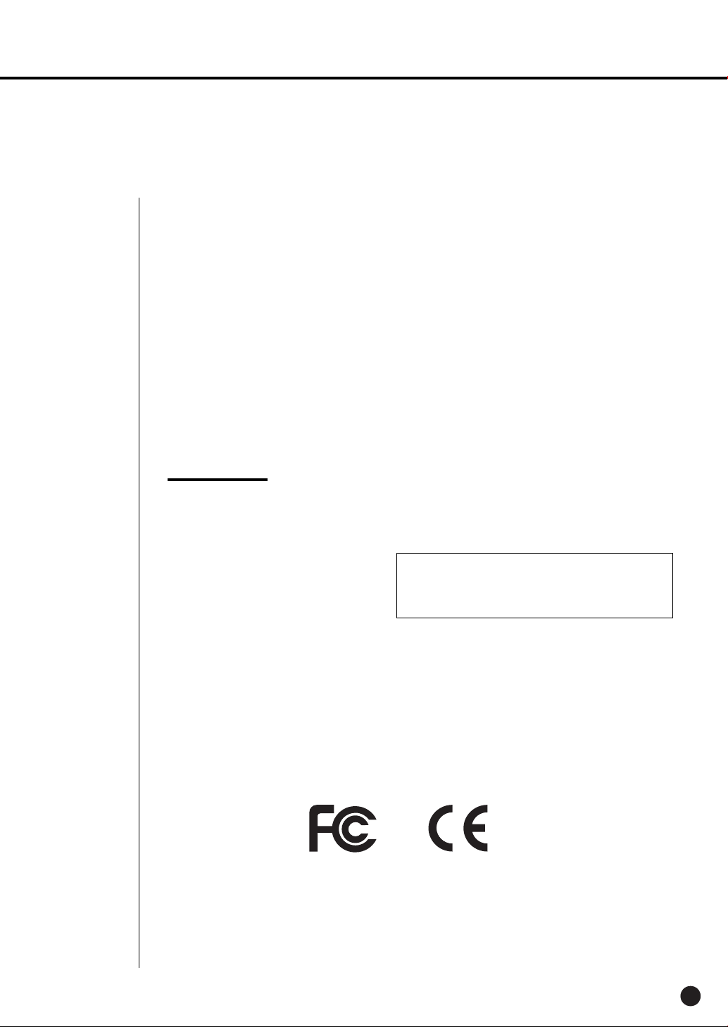
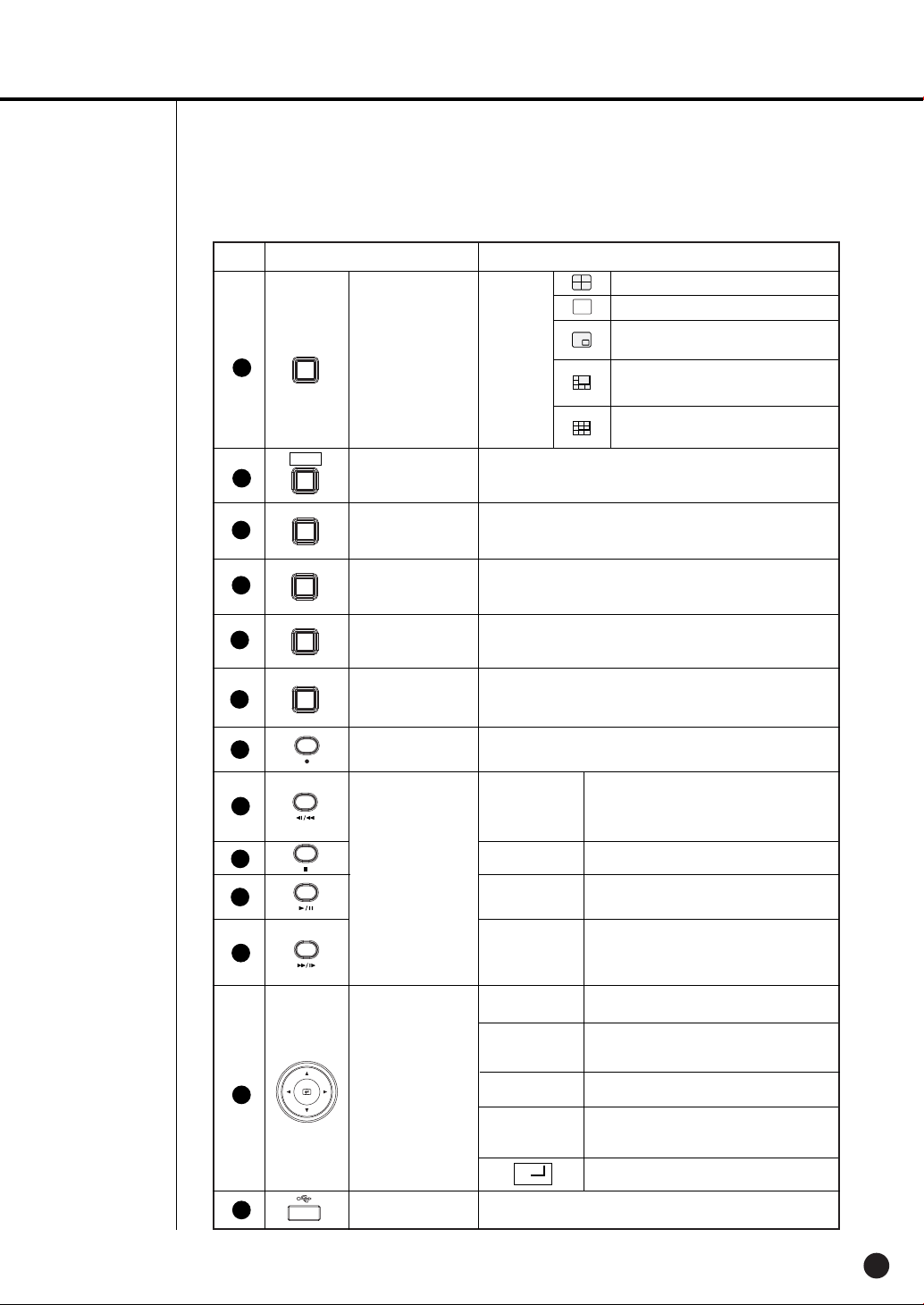
Part Names and Functions
[SHR-2040]
No. Name Function
Power LED
Alarm LED
HDD Access
1
1 4
2
3
4
5
...
AUDIO
ALARM
MODE
LED
Network LED
Backup LED
Rec LED
Channel Button
Audio Setup
Button
Alarm Setup
Button
Split Screen
Selection Button
Displays power on/off condition.
lights on when an event occurs.
Displays Normal Access to HDD. Upon Access to HDD, LED
repeats on and off.
Displays both network connection and data transmission conditions.
Displays Back Up Mode.
Displays the record condition.
Selects a channel in the Single Mode. Used for number
input button in the number input mode.
Sets the Audio On/Off.
Cancels the alarm when the Alarm button is selected.
Displays 4 split screen.
Display
Mode
Displays PIP(Picture in Picture) screen.
The single channel screen is changed
according to the time set on the menu.
Displays 4 split screen.
1-3
English
MODE
6
Mode Selection
Button
Search
Displays both LIVE Channel and Playback
Channel in the PIP Screen simultaneously.
Displays 6 split screen.
(1 CH playback screen and 4 CH live screen)
Displays 9 split screen.
(4 CH playback screen and 4 CH live screen)
Page 11
No. Name Function
7
PTZ
PTZ Button
Performs the TELE, WIDE, PRESET, and VIEW function.
12
13
14
15
16
10
11
17
ZOOM
8
9
TELE
FREEZE
WIDE
SEARCH
VIEW
MENU
PRESET
ZOOM(TELE)
Button
FREEZE(WIDE)
Button
SEARCH(VIEW)
Button
MENU (PRESET)
Button
RECORD
Search Function
Key
Direction Button
Key
Sets up Digital Zoom(x2).
( Performs the TELE function by pressing the PTZ button.)
Performs the FREEZE function in the DISPLAY Mode.
( Performs the WIDE function by pressing the PTZ button.)
Displays the search method.
( Performs the VIEW function by pressing the PTZ button.)
Displays the system setup menu or enters to the upper
menu.( Performs the PRESET setup function by pressing
the PTZ.)
Records the record setup set in the normal record mode.
Fast/Step
Reverse
STOP
PLAY/PAUSE
Fast/Step
Forward
¦
¦
Fast Reverse: Used for the fast rewinding
search in the playback mode.
Step Reverse: Used for the 1 step reverse
search during the pause.
Used for the search stop in the playback mode.
Toggles in the playback mode to activate
PLAY/PAUSE.
Fast Forward: Used for the fast-forwarding
search in the playback mode.
Step Forward: Used for the 1 step-forwarding
search during the pause.
In case of setting the details of Menu, it is
used as Direction Key. (For PTZ Operation)
In case of setting the details of Menu, it
increases the value or it is used as Direction
Key. (For PTZ Operation)
In case of setting the details of Menu, it is
used as Direction Key. (For PTZ Operation)
In case of setting the details of Menu, it
decreases the value or it is used as Direction
Key. (For PTZ Operation)
Acts as the Enter key for the menu setup.
18
USB Port
Connects the USB type device.
English
1-4
Page 12
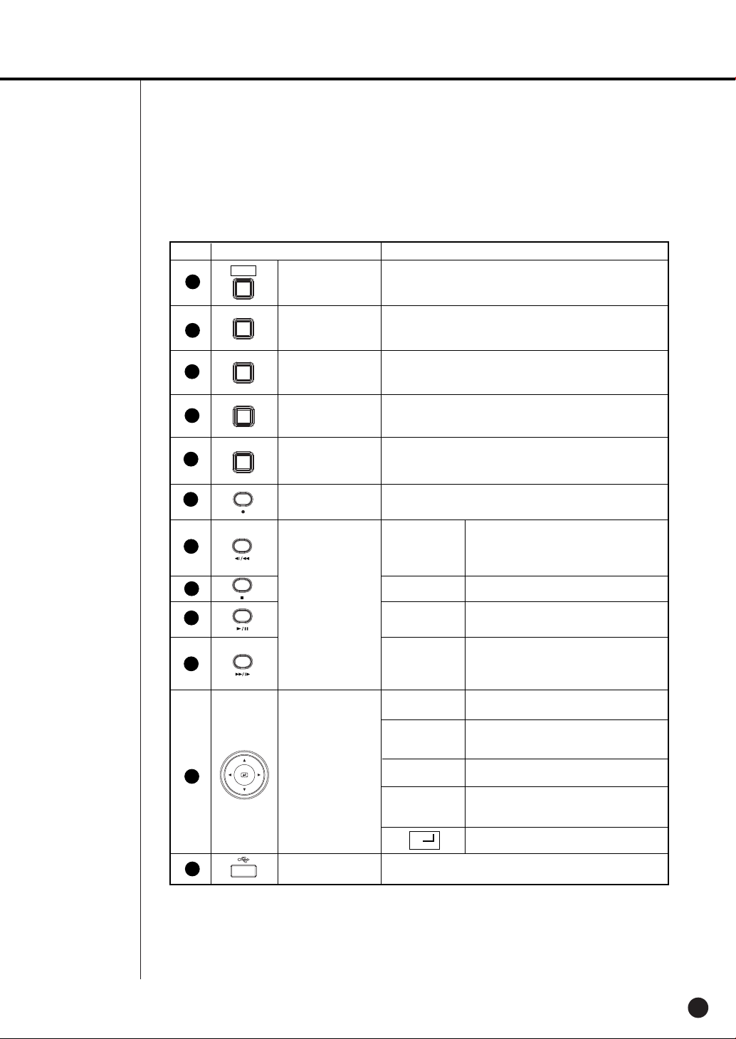
SHR-2040/2041/2042 USER’S MANUAL
[SHR-2041]
[SHR-2042]
No. Name Function
Power LED
Alarm LED
HDD Access
1
LED
Network LED
Backup LED
Rec LED
2
1 4
3
4
5
6
...
AUDIO
ALARM
MODE
Eject Button
Channel Button
Audio Setup
Button
Alarm Setup
Button
Split Screen
Selection Button
Displays power on/off condition.
lights on when an event occurs.
Displays Normal Access to HDD. Upon Access to HDD, LED
repeats on and off.
Displays both network connection and data transmission conditions.
Displays Back Up Mode.
Displays the record condition.
Performs the OPEN/CLOSE of CD/RW.
Selects a channel in the Single Mode. Used for number
input button in the number input mode.
Sets the Audio On/Off.
Turns off the alarm LED and stops the sound when an
alarm is issued.
Alarm icon disappears when the alarm button is used.
Displays 4 split screen.
Display
Mode
Displays PIP(Picture in Picture) screen.
Auto Sequence Mode: The single channel screen
is changed according to the time set on the menu.
1-5
English
Page 13
No. Name Function
Displays 4 split screen.
Displays the selected channel to the Single Mode
Displays both LIVE Channel and Playback
Channel in the PIP Screen simultaneously.
Displays 6 split screen.
(1 CH playback screen and 4 CH live screen)
Displays 9 split screen.
(4 CH playback screen and 4 CH live screen)
11
12
10
MODE
7
PTZ
8
ZOOM
9
TELE
FREEZE
WIDE
SEARCH
VIEW
MENU
PRESET
Mode Selection
Button
PTZ Button
ZOOM(TELE)
Button
FREEZE(WIDE)
Button
SEARCH(VIEW)
Button
MENU (PRESET)
Button
Search
Performs the TELE, WIDE, PRESET, and VIEW function.
Sets up Digital Zoom(x2).
( Performs the TELE function by pressing the PTZ button.)
Performs the FREEZE function in the DISPLAY Mode.
( Performs the WIDE function by pressing the PTZ button.)
Displays the search method.( Performs the VIEW function
by pressing the PTZ button.)
Displays the system setup menu or enters to the upper
menu.( Performs the PRESET setup function by pressing
the PTZ.)
13
14
15
16
17
18
19
RECORD
Search Function
Key
Direction Button
Key
USB Port
Records the record setup set in the normal record mode.
Fast/Step
Reverse
STOP
PLAY/PAUSE
Fast / Step
Forward
¦
¦
Connects the USB type device.
Fast Reverse: Used for the fast rewinding
search in the playback mode.
Step Reverse: Used for the 1 step reverse
search during the pause.
Used for the search stop in the playback mode.
Toggles in the playback mode to activate
PLAY/PAUSE.
Fast Forward: Used for the fast-forwarding
search in the playback mode.
Step Forward: Used for the 1 step-forwarding
search during the pause.
In case of setting the details of Menu, it is
used as Direction Key. (For PTZ Operation)
In case of setting the details of Menu, it
increases the value or it is used as
Direction Key. (For PTZ Operation)
In case of setting the details of Menu, it is
used as Direction Key. (For PTZ Operation)
In case of setting the details of Menu, it
decreases the value or it is used as
Direction Key. (For PTZ Operation)
Acts as the Enter key for the menu setup.
English
1-6
Page 14
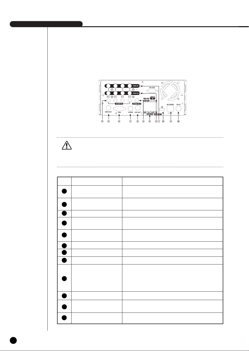
SHR-2040/2041/2042 USER’S MANUAL
Caution
Caution
Do not play DVR on the carpet or other soft material to prevent clogging of the air ventilator.
To play DVR on the cabinet or rack, be sure to check the ventilation condition.
[SHR-2040]
No. Name Function
12
10
11
1
2
3
4
5
6
7
8
9
VIDEO IN
THROUGH
AUDIO IN
AUDIO OUT
VIDEO OUT
VGA
S-VIDEO
SPOT OUT
ALARM
USB
NETWORK
DC-IN
Composite Video Signal Input Port (BNC Style Connector)
You may use THROUGH port to transmit a video signal to the
other video equipment.
Audio Signal Input Port (RCA Jack)
Audio Signal Output Port (RCA Jack)
Composite Video Signal Output Port (BNC Style Connector)
VGA Video Signal Output Port
S-VIDEO Video Signal Output Port
SPOT Out Output Port (BNC Style Connector)
- ALARM IN 1~4 : Alarm Input Port
- ALARM RESET IN : Alarm Reset Port
- ALARM OUT1~2 : Alarm Output Port
- TX+, TX-, RX+, RX- : RS-485 Communication
USB connection Port
Network Connection Port
12V Power Socket Support
1-7
English
Page 15

[SHR-2041/2042]
Caution
Caution
Do not play DVR on the carpet or other soft material to prevent clogging of the air ventilator.
To play DVR on the cabinet or rack, be sure to check the ventilation condition.
No. Name Function
12
10
11
1
2
3
4
5
6
7
8
9
VIDEO IN
THROUGH
AUDIO IN
AUDIO OUT
VIDEO OUT
VGA
S-VIDEO
SPOT OUT
ALARM
USB
NETWORK
AC-IN
Composite Video Signal Input Port (BNC Style Connector)
You may use THROUGH port to transmit a video signal to the
other video equipment.
Audio Signal Input Port (RCA Jack)
Audio Signal Output Port (RCA Jack)
Composite Video Signal Output Port (BNC Style Connector)
VGA Video Signal Output Port
S-VIDEO Video Signal Output Port
SPOT Out Output Port (BNC Style Connector)
- ALARM IN 1~4 : Alarm Input Port
- ALARM RESET IN : Alarm Reset Port
- ALARM OUT1~2 : Alarm Output Port
- TX+, TX-, RX+, RX- : RS-485 Communication
USB connection Port
Network Connection Port
(NTSC) AC 110~220V Power Socket Support
(PAL) AC 100~230V Power Socket Support
English
1-8
Page 16

Page 17

Chapter 2
Installation
Page 18
SHR-2040/2041/2042 USER’S MANUAL
1
Installation Environment Setup
Do not play DVR on the carpet or other soft material to prevent clogging of the air ventilator.
To play DVR on the cabinet or rack, be sure to check the ventilation condition.
You should pay attention to the following before you use the product.
1. Do not use it outdoor.
2. Do not let water or liquid in the connection part or the product itself.
3. Do not impose excessive shock or force.
4. Do not pull out the power plug unreasonably.
5. Do not disassemble the product on your own.
6. Do not exceed the rated input or output range.
7. Use certified power cord only.
8. Use the power cord with a ground for the product with an input ground.
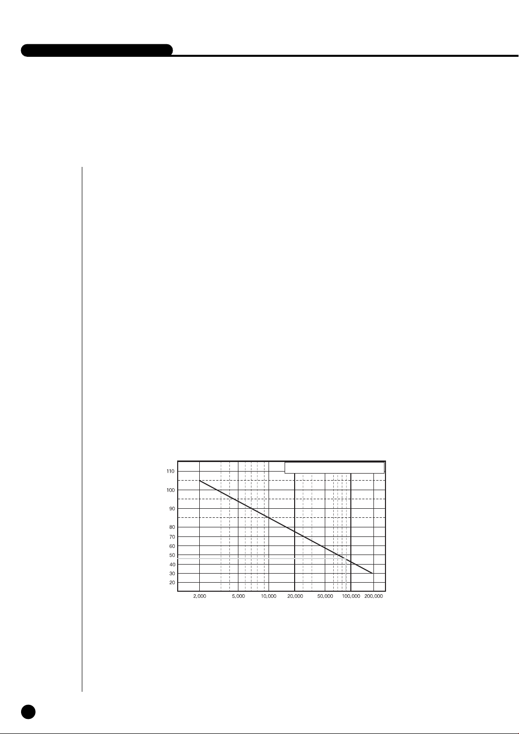
Samsung Digital Video Recorder (hereafter “DVR”) is a high-tech security equipment
that contains a high-capacity HDD and top-notch circuits. High temperature inside or
outside of the product may cause reduced life and deteriorated performance (see
graph 1 below), leading to a malfunction. So please follow the instructions below to
proceed with the installation.
2-1
English
Temperature
(Unit:°C)
One Year:24 HR X 365 DAY = 8,760 HR
Life (Unit:HOURS)
<Graph 1 : Correlation between temperature and product life>
Page 19
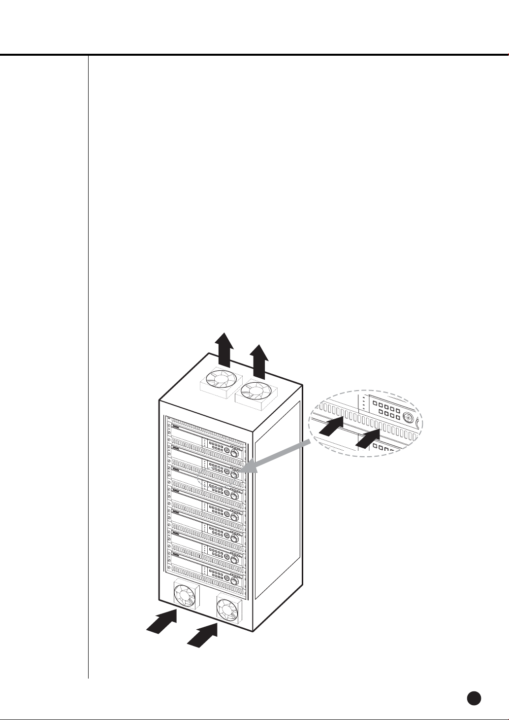
<Instructions for the rack mounting of Samsung DVR>
1. The rack on which the DVR is mounted should not be sealed off.
2. And it also can allow air circulation through the vent.
3. As in the figure to the right, we recommend the product should be stacked up with other
DVRs or rack-mounting devices at a certain space or you install a vent system to
accommodate airflow.
4. For forming a natural convection, the air intake hole should be positioned at the bottom and
the emission at the top.
5. We recommend you install each of the air intake and emission holes with a fan motor for
sufficient airflow.
(The air intake fan should be equipped with a filter to block dust and other impurities from
inflow.)
6. The temperature inside the rack and around the DVR should stay between 0°C and 40°C
(32°F and 104°F).
English
2-2
Page 20
SHR-2040/2041/2042 USER’S MANUAL
2
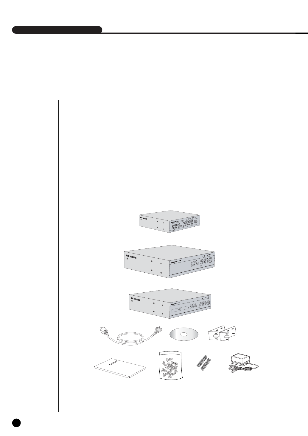
Checking Product & Accessory
Upon delivery of a product, you shall unwrap the product and put it on the even floor or where
you want to use it. Then you shall check if the following items are in it.
■ Main Body
■ User’s Manual
■ One Power Cord
■ Two Brackets
- These are not supplied in SHR-2040.
- Brackets are used to attach the product to the rack.
■ Smart Viewer Software CD (PDF Manual included)
■ Special Screws
- SHR-2041 : SCREW-SPECIAL 12EA
- SHR-2042 : SCREW-SPECIAL 4EA
- SHR-2040 : SCREW 4EA (Code : 6001-000742)
- Please keep special screws for HDD addition.
■ 2 EA of RS-485/Alarm Terminal Block
Main Body
SHR-2040
2-3
English
Main Body
SHR-2041
Main Body
Power Cord
User’s Manual
WARNING) SHR-2040 set must use the adapter we provide.
Adapter : ADP-5412
SHR-2042
Screw
CD
RS-485/Alarm
Terminal Block
Bracket
Adapter
(Only 2040)
Page 21
3
HDD Addition
Caution
Caution
[Checking HDD Data]
Please, pay attention to Following information to minimize the chance of losing HDD data.
- Remember that you should protect HDD from any impact or misuse as this may cause damaged.
- The Manufacturer is not responsible for missing data or defects caused by the user’s mishandling.
Note: Adding Extra HDD. Check in advance that the HDD is compatible with the manufacturer’s DVR.
Examples that can cause loss of data or damage HDD.
- Any outside Impact on the case which could happen whilst disassembling or setting up the DVR.
- Power cut or incorrect shutdown whilst the DVR is operating.
- Refer to page 5-11 : how to turn off DVR
- Moving or causing any impact on the DVR during operation. Please, back up events as soon as possible to minimize
disappointment should HDD data be lost.
SHR-2040 HDD ADDITION
The user can add 1 HDD to this product. However, there are many factors that can cause electrical shock, accidents, and malfunctioning of the device inside of the product. When the user
does not correctly install or apply the proper settings, the device may not recognize the HDD or
the device will not run. Therefore, before adding any HDDs, it is recommended that the user
contacts a specialist where they purchased the product.
[Caution when adding a HDD]
■ When adding HDDs, pay attention so that the cable doesn’t get caught between unsuitable places
or the cable’s insulation doesn’t come off. (This may cause a malfunction or fire.)
■ When adding HDDs, be careful not to receive any injury from the pointed edges inside the product.
■ Pay attention so as not to lose the disassembled screws or accessories.
If the screws or accessories are not put together, the product will either malfunction or won’t be
able to operate.
■ Check the compatibility list of HDDs before installing additional HDDs. The list of the compatible
devices with Samsung DVR can be obtained from your vendor.
■ If you contact the RTC battery while adding hard disks, the battery failure may happen. In this
case, you will encounter failures when setting the time and operating DVR.
■ If you don’t connect fan power cables after adding hard disks, the fan failure message appears on
the screen. This can cause operation failures because it raises the temperature inside your DVR.
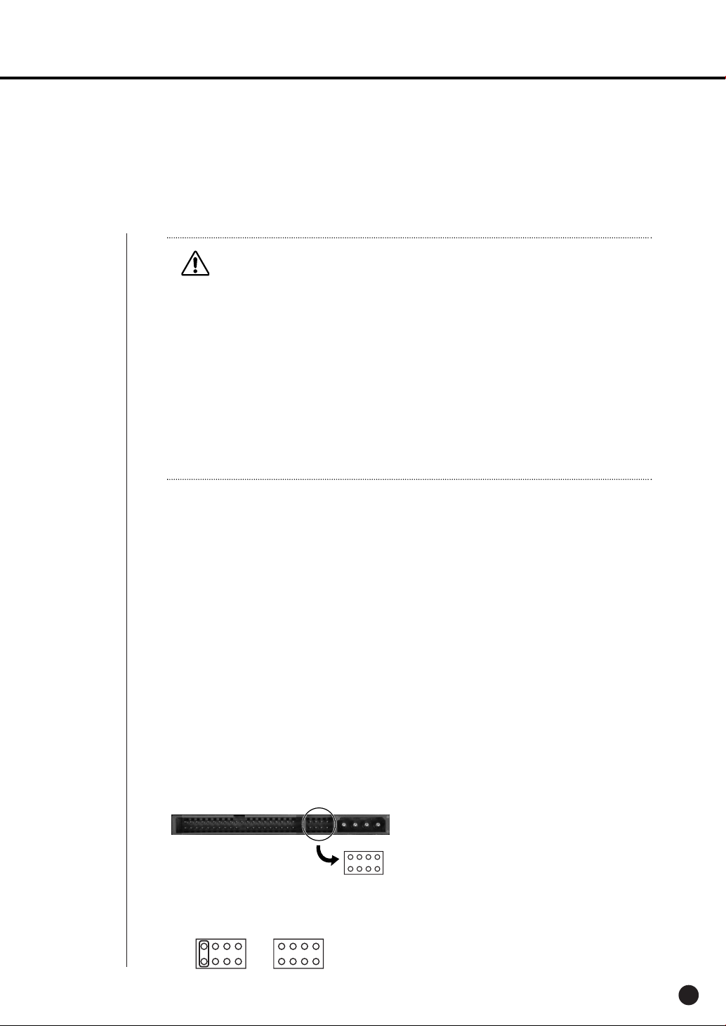
[Setting the Jumper]
The jumper setting method is illustrated on the surface of the purchased HDD.
Using SAMSUNG hard disk, the jumper setting method is as follows:
• HDD jumper for Primary Master and Primary Slave.
English
2-4
Page 22
SHR-2040/2041/2042 USER’S MANUAL
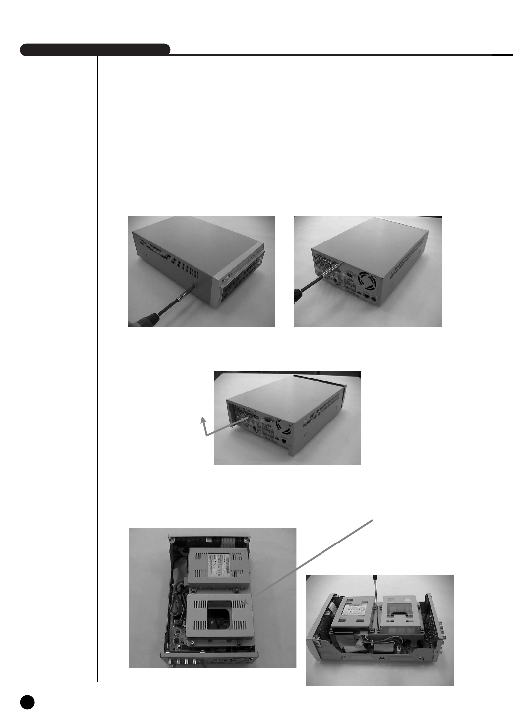
[How to Add a HDD]
1. To remove the product’s cover, take out the screws on the left and right sides (2 spots each)
and on the back (3 spots).
2. Remove the cover from the product. (Remove the cover by first lifting its back part upward
after sliding the cover slightly backward.)
3. There is bracket-HDD mounted on the back where you can mount a HDD, and you have to
remove the screws (4 spots) that are holding the bracket that you want to mount an HDD onto.
BRACKET-HDD
2-5
English
Page 23
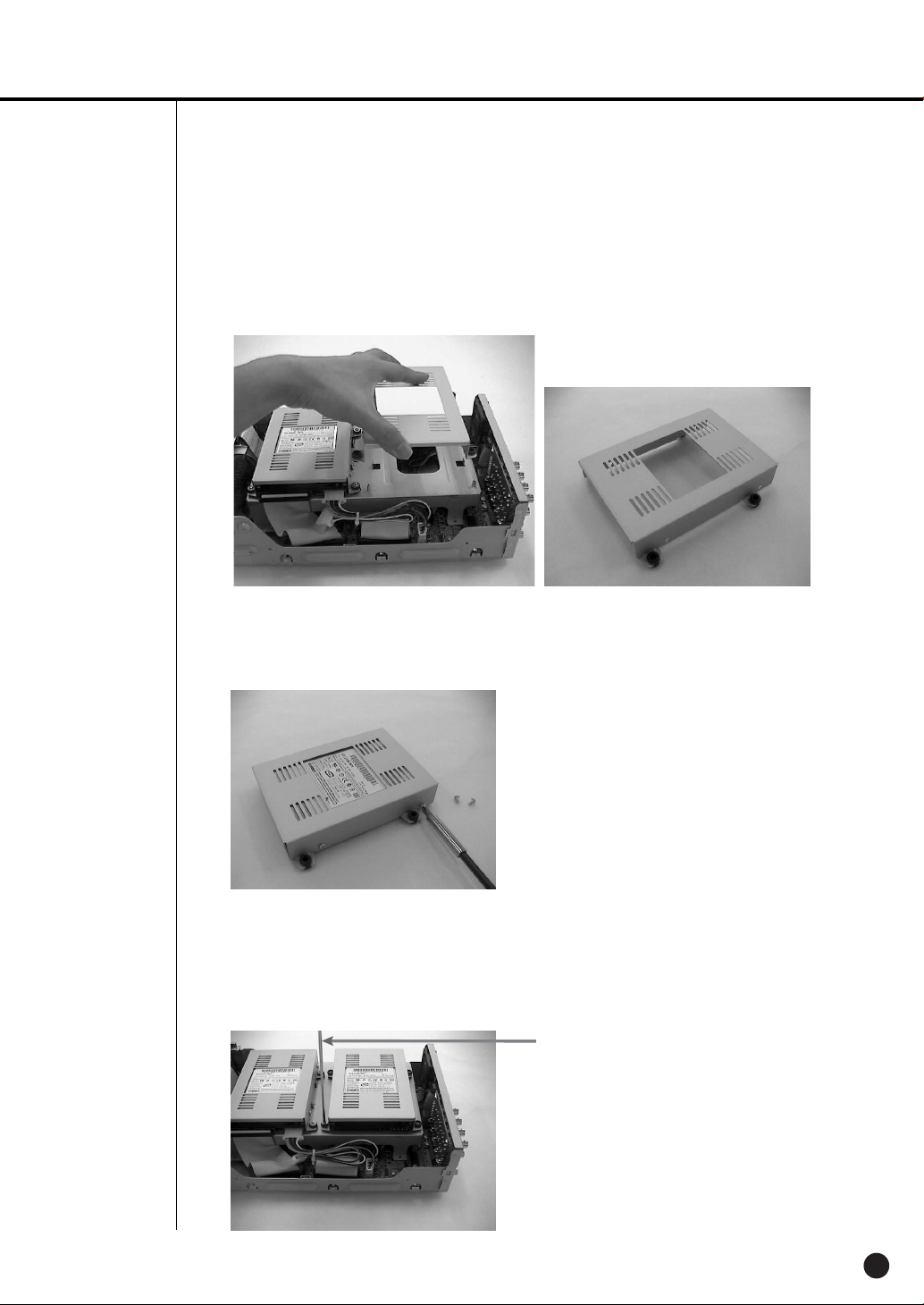
4. Remove the bracket-HDD from the product by lifting it upward from the product.
5. Mount the HDD to the bracket-HDD with the SCREW-TAPTITE (BW, +, S, M3, L6, ZPC)
(4 spots) that was provided as an accessory. (The screws have to be tightened so that it
doesn’t vibrate loose.)
6. Re-mount the built-in HDD bracket-HDD to the place where it was separated from.
The work order for mounting the BRACKET-HDD is in reverse from when disassembling it.
Tighten the screw after the BRACKET-HDD’s mounting holes are perfectly aligned with four
mounting spots on the bottom.)
SCREWDRIVER
English
2-6
Page 24
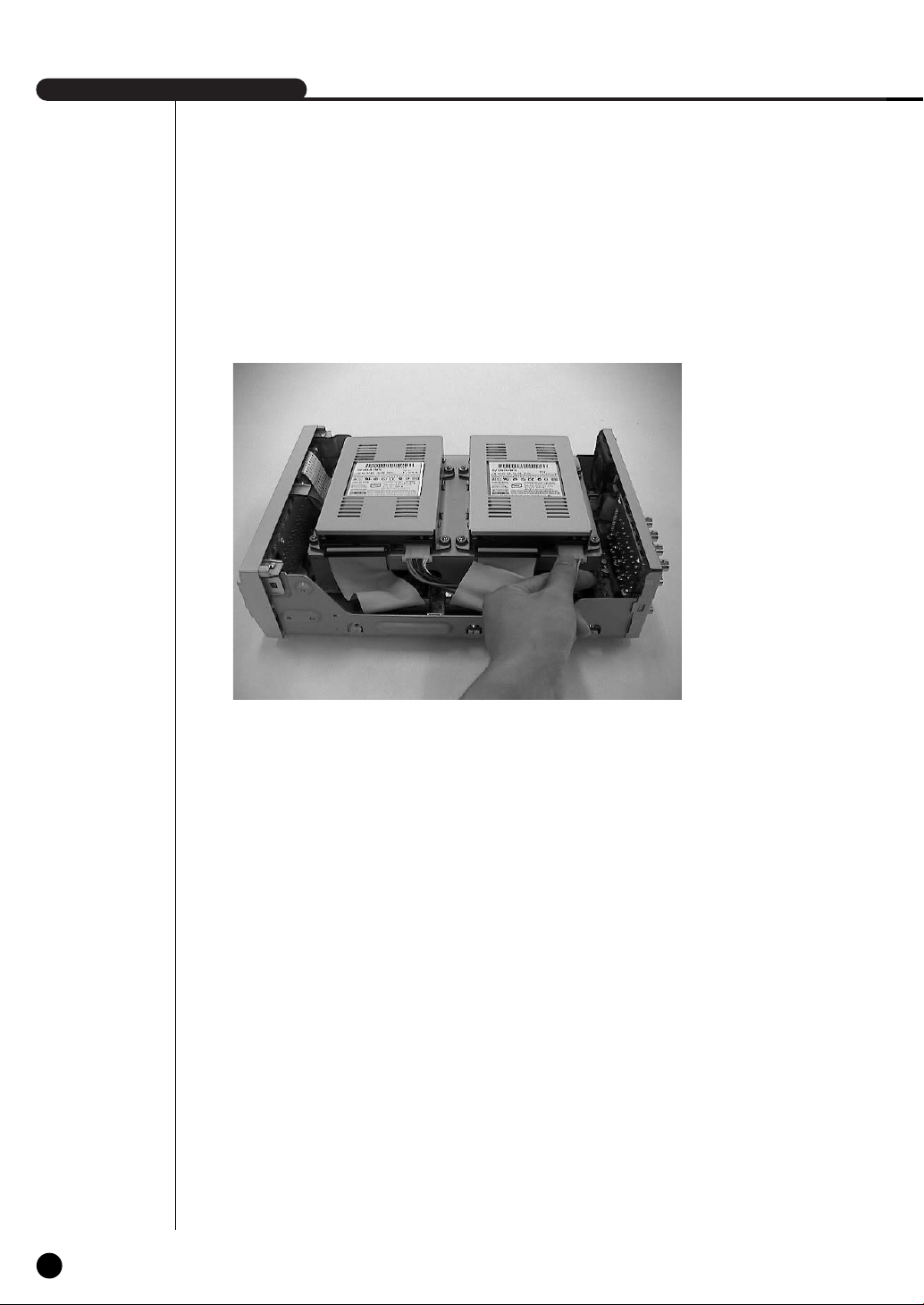
SHR-2040/2041/2042 USER’S MANUAL
7. Make sure that the bracket-HDD is mounted stably inside the product, then connect the
power supply cable and signal transmission cable (IDE cable) to the HDD.
2-7
8. Check if there is any problem with connector or wiring inside of the product for connecting
and mounting then close the cover.
9. Tighten cover mounting screws. (The left and right side each has 2 spots and the back side
has 3 spots)
English
Page 25
SHR-2041 HDD ADDITION
The user can add 3 HDDs to this product.
However, there are many factors that can cause electrical shock, accidents, and malfunctioning
of the device inside of the product. When the user does not correctly install or apply the proper
settings, the device may not recognize the HDD or the device will not run. Therefore, before
adding any HDDs, it is recommended that the user contacts a specialist where you purchased
the product.
[Caution when adding a HDD]
■ When adding HDDs, pay attention so that the cable doesn’t get caught between unsuitable places
or the cable’s insulation doesn’t come off. (This may cause a malfunction or fire.)
■ When adding HDDs, be careful not to receive any injury from the pointed edges inside the product.
■ Pay attention so as not to lose the disassembled screws or accessories.
If the screws or accessories are not put together, the product will either malfunction or will be inop
erable.
■ Check the compatibility list of HDDs before installing additional HDDs. The list of the compatible
devices with Samsung DVR can be obtained from your vendor.
■ If you contact the RTC battery while adding hard disks, the battery failure may happen. In this
case, you will encounter failures when setting the time and operating DVR.
■ If you don’t connect fan power cables after adding hard disks, the fan failure message appears on
the screen. This can cause operation failures because it raises the temperature inside your DVR.
[Setting the Jumper]
The jumper setting method is illustrated on the surface of the purchased HDD.
Using SAMSUNG hard disk, the jumper setting method is as follows:
• HDD jumper for Primary Master and Primary Slave.
• Jumper setting for Secondary Master and Secondary Slave.
[How to Add a HDD]
1. To remove the product’s cover, take out the screws on the left and right sides (5 spots each)
and on the back (1 spot).
English
2-8
Page 26

SHR-2040/2041/2042 USER’S MANUAL
2. Remove the cover from the product. (Remove the cover by first lifting its back part upward
after sliding the cover slightly backward.)
3. There is a bracket (bracket-HDD) mounted on the right and left sides where you can mount
the HDD, and you have to remove the screws that are holding the bracket that you want to
mount an HDD onto.
BRACKET-HDD
SCREWDRIVER SCREWDRIVER
2-9
English
Page 27

4. Remove the bracket-HDD from the product by separating the power supply cable, signal
transmission cable (IDE cable), and fan cable then pulling it toward the center of the product
to separate its fixed part from the bottom.
5. Mount the HDD to the bracket-HDD with the SCREW-SPECIAL (BWH, 6-32UNC, L10.5)
(4 spots) that was provided as an accessory. (The screws have to be tightened so that it
doesn’t vibrate loose.)
English
2-10
Page 28

SHR-2040/2041/2042 USER’S MANUAL
6. Re-mount the built-in HDD bracket-HDD to the place where it was separated from.
Place the bracket-HDD so that all five mounting spots on the bottom and the bracket-HDD’s
mounting holes are perfectly aligned, then slide it toward the outside of the product and tigh
ten the screws.
7. Make sure that the bracket-HDD is mounted stably inside of the product, then connect the
power supply cable, signal transmission cable (IDE cable), and fan cable to the HDD.
MASTER HDD
SLAVE HDD
8. Check if there is any problem with connector or wiring inside of the product for connecting
and mounting then close the cover.
9. Tighten cover mounting screws. (The left and right side each has 5 spots and the back side
has 1 spot)
2-11
English
Caution
Caution
When mounting an additional HDD, the primary master has to be mounted.
Page 29

SHR-2042 HDD ADDITION
The user can add up to 2 HDDs to this product.
However, there are many factors that can cause electrical shock, accidents, and malfunctioning
of the device inside of the product. When the user does not correctly install or apply the proper
settings, the device may not recognize the HDD or the device will not run. Therefore, before
adding any HDDs, it is recommended that the user contacts a specialist where they purchased
the product.
[Caution when adding a HDD]
■ When adding HDDs, pay attention so that the cable doesn’t get caught between unsuitable places
or the cable’s insulation doesn’t come off. (This may cause a malfunction or fire.)
■ When adding HDDs, be careful not to receive any injury from the pointed edges inside the product.
■ Pay attention so as not to lose the disassembled screws or accessories.
If the screws or accessories are not put together, the product will either malfunction or will be inop
erable.
■ Check the compatibility list of HDDs before installing additional HDDs. The list of the compatible
devices with Samsung DVR can be obtained from your vendor.
■ If you contact the RTC battery while adding hard disks, the battery failure may happen. In this
case, you will encounter failures when setting the time and operating DVR.
■ If you don’t connect fan power cables after adding hard disks, the fan failure message appears on
the screen. This can cause operation failures because it raises the temperature inside your DVR.
[Setting the Jumper]
The jumper setting method is illustrated on the surface of the purchased HDD.
Using SAMSUNG hard disk, the jumper setting method is as follows:
• HDD jumper for Primary Master and Primary Slave.
• Jumper setting for Secondary Master (CD-RW) and Secondary Slave.
[How to Add a HDD]
1. To remove the product’s cover, take out the screws on the left and right sides (5 spots each)
and on the back (1 spot).
English
2-12
Page 30
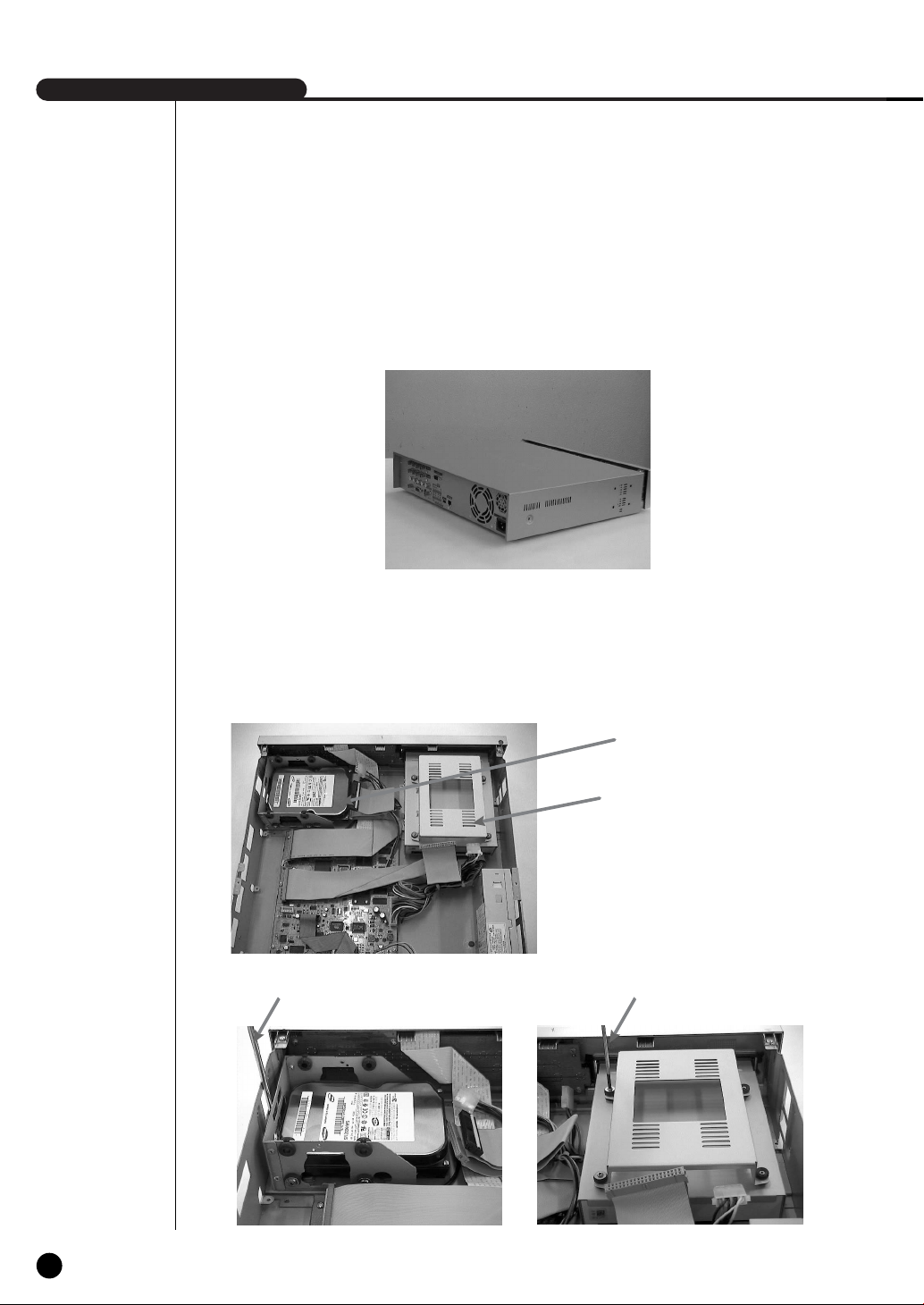
SHR-2040/2041/2042 USER’S MANUAL
2. Remove the cover from the product. (Remove the cover by first lifting its back part upward
after sliding the cover slightly backward.)
3. There is a bracket (bracket-HDD) mounted on the right and left sides where you can mount
the HDD, and you have to remove the screws that are holding the bracket that you want to
mount an HDD onto.
BRACKET-HDD(A)
BRACKET-HDD(B)
SCREWDRIVER SCREWDRIVER
2-13
English
Page 31

4. Remove the bracket-HDD (A) from the product by disconnecting the power supply cable,
signal transmission cable (IDE cable), and fan cable then pulling it toward the center of the
product to disconnect its fixed part from the bottom. Remove the bracket-HDD (B) by lifting it
up after removing the screws.
5. Mount the HDD to the bracket-HDD with the (A)SCREW-SPECIAL (BWH,6-32UNC,L10.5)
and (B)SCREW-TAPTITE (BH,+,S,M3,L6,ZPC) (4 spots) that was provided as an accessory.
(The screws have to be tightened so that it doesn’t vibrate loose.)
English
2-14
Page 32

SHR-2040/2041/2042 USER’S MANUAL
6. Re-mount the built-in HDD bracket-HDD to the place where it was removed from.
Place the bracket-HDD(A) so that all the five fixing areas in the bottom and the
bracket-HDD’s fixing holes can perfectly aligned, then slide it outward of the product and
tighten the screws. For the bracket-HDD (B), place it so that all the four fixed areas at the
bottom and the bracket-HDD’s fixed holes can perfectly aligned, then tighten the screws.)
7. Make sure that the bracket-HDD is mounted stably inside of the product, then connect the
power supply cable and signal transmission cable (IDE cable) to the HDD.
MASTER HDD
SLAVE HDD
2-15
English
Page 33

8. Check if there is any problem with connector or wiring inside of the product for connecting
and mounting then close the cover.
9. Tighten cover mounting screws. (The left and right side each has 5 spots and back side has
1 spot)
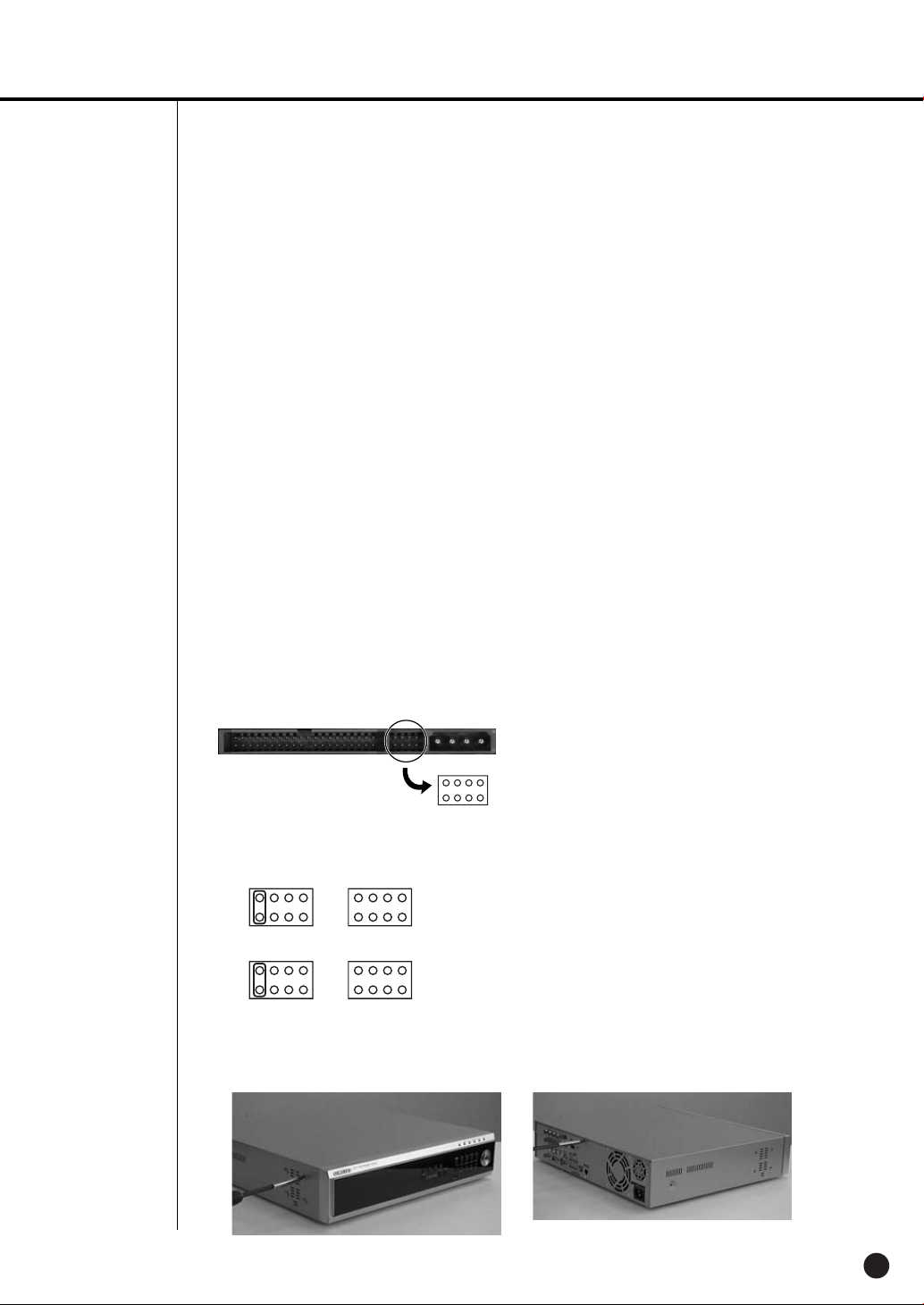
Caution
Caution
When mounting an additional HDD, the primary master has to be mounted.
The HDD has to be set as the primary master, and the CD-RW has to be set as the secondary
master.
When adding a HDD, please add the same kind of HDD that you used for this product.
For HDD addition, please select the same HDD with the existing HDD fixed to the product as
far as possible.
- Jumper settings when mounting 2 SHR-2040 HDDs
Due to the limited space, set the jumper for both HDDs to the master mode for the
SHR-2040.
➝ 1st HDD : Master mode (Primary IDE Cable),
2nd HDD : Master mode (Secondary IDE Cable)
- Extra precaution is necessary for the SHR-2042. The built-in CD-RW is set up as the
secondary mater.
➝ 1st HDD : Master mode (Primary IDE Cable),
2nd HDD : Slave mode (Primary IDE Cable),
3rd HDD : Slave Mode (Secondary IDE Cable)The internal CD-RW is connected to the
secondary master.) respectively
Both HDDs attached to Primary Slot and Secondary Slot should be set to Master and Slave
respectively. Refer to User’s Manual for Master or Slave Jumper Setting.
In the event of only one HDD installation, it shall be inserted into the Primary slot.
English
2-16
Page 34

SHR-2040/2041/2042 USER’S MANUAL
WARNING
! Regarding the sub fan, you need additional brackets and sub fans as follows.
The sub fan is shaped like this when viewed from the front and back. Please pay attention to
the fan direction to let wind go through the fan.
2-17
@ Fix the fan as follows
English
Page 35

# Please install the fan which is seen at the right from the front view of SHR-set as follows.
$ The cable should be out from the left hole.
English
2-18
Page 36

Page 37

Chapter 3
Connecting with
other device
Page 38

SHR-2040/2041/2042 USER’S MANUAL
1
Connecting the Video, Audio, and Monitor
3-1
[SHR-2040]
English
Page 39

[SHR-2041/2042]
English
3-2
Page 40

SHR-2040/2041/2042 USER’S MANUAL
2
Connecting the Network
● Connecting to Internet through Ethernet(10/100BaseT)
[SHR-2040]
3-3
● Connecting to Internet through ADSL
[SHR-2040]
English
Page 41

● Connecting to Internet through Ethernet(10/100BaseT)
[SHR-2041/2042]
● Connecting to Internet through ADSL
[SHR-2041/2042]
English
3-4
Page 42

SHR-2040/2041/2042 USER’S MANUAL
3
Connecting the USB
1. There are two USB connecting ports on the front and back of SHR-2040/2041/2042.
2. USB Hard Disk, USB CD/DVD, and USB Memory are connected through the front and back
ports of SHR-2040/2041/2042.
3. Only one USB device can be connected with each USB connecting port.
4. If the USB HDD is connected to the system, it should be detected and set through
Menu - System - HDD setup before the operation.
5. It supplies the function of HOT PLUG, which connects/removes the USB device, during the
system operation.
Note
Note
See 5-8 System (HDD Setup) of User’s Manual.
Caution
Caution
- USB port on the front and back of SHR-2040/2041/2042 cannot be connected to same kinds
of USB device. (For example, the case is that 2 CD-RW devices or 2 USB Memories are used
by connection with the front and back of system.)
- If you use the USB Memory on SHR-2040/2041/2042, it should be composed of the format
being supported by SHR-2040/2041/2042. Although you format it with FAT32 format on PC,
it will be re-formatted, in case of (when) connecting with SHR-2040/2041/2042.
3-5
English
Caution
Caution
- The hard disk of USB device should be set to Master.
Page 43

4
Connecting the Alarm Input/Output
The Alarm IN/OUT port in the back of SHR-2040/2041/2042 is composed of the following
elements.
● ALARM IN/OUT Connection
Name Function
- ALARM IN1
1 - ALARM IN2
- ALARM IN3
- ALARM IN4
ALARM Input Port
2 - ALARM RESET IN
3 - ALARM OUT1
- ALARM OUT2
On receiving an ALARM RESET signal, the
system cancels the current ALARM input and
output signal and then resumes sensing.
ALARM Output Port
English
3-6
Page 44

SHR-2040/2041/2042 USER’S MANUAL
● ALARM IN/OUT Connection
3-7
English
Page 45

5
Connecting the RS-485 Device
● Connect the RS-485 Device through the back port of SHR- SHR-2040/2041/2042.
● You can install and control the PTZ camera supporting the RS-485 communication.
● You can adopt either Half Duplex or Full Duplex method for the connection.
PTZ device SHR-2040/2041/2042
Half Duplex Type
Data (–)
Data (+)
Full Duplex Type
Rx(+)
Rx(–)
Tx(–)
Tx(+)
● Baud Rate supports 600 / 1200 / 2400 / 4800 / 9600 / 19200 / 38400.
Caution
Caution
Check if RS-485 device is compatible with SHR-2040/2041/2042 first.
Then pay attention not to change the polarity(+, -) of RS-485 when connecting it.
Rear
Tx(–)
Tx(+)
Rx(–)
Rx(+)
English
3-8
Page 46

Page 47

Chapter 4
Live
Page 48

SHR-2040/2041/2042 USER’S MANUAL
1
System Operation
● Turn the power on and the following LOGO pops up on the screen.
● After the LOGO appears, all of LED in the front flickers 6 times to initialize the system for
operation.
● Upon completion of normal initialization, the Live screen appears accompanying a beep
sound.
● It requires 30 to 40 seconds until the Live screen appears.
Note
Note
4-1
English
If a new HDD is installed, it may require more time to be appeared the Live screen due to the
initialization time of a new HDD.
If the Live screen does not appear continuously or the LED in front repeats flickering, please
check the connection between inside and outside. If the system does not operate in normal,
contact with the shop where you bought the product.
● The Live screen does not affect the earlier MENU setup. If you reboot the system
after power-off during recording, the Live screen will appear, accompanying recording.
Note
Note
If the Live screen dose not appear, check if the Video Out comes out in Composite mode or
VGA mode.
Page 49

2
Live Screen Mode
Definition of Live Screen Icon
The Live screen icons display the current setup and function status of each screen.
V.Loss
CAM_01
: Recording Icon
Each icon represents Normal / Event (Alarm + Motion) / Schedule Recording.
: Recording Video Size Icon
Each icon represents the recording size of Large / Normal / CIF.
- Large : Full D1 - (NTSC) 720X480 (PAL) 720X576
- Normal : Half D1 - (NTSC) 720X240 (PAL) 720X288
- CIF : CIF - (NTSC) 352X240 (PAL) 352X288
(Full D1 is supported only when “1 CH DVR support”)
: Recording lock icon
It indicates record lock while in record setup.
This icon appears while recording with the recording lock set.
You have to enter a password to cancel the recording.
CAM_01
: PTZ Icon
This icon appears when setting the PTZ device with the PTZ icon and changes to
yellow color when operating the PTZ.
: Audio Icon
This icon represents the Audio On/Off status and changes to yellow color at the
Audio On. It does not appear in the Video mode or Audio Disable.
: Sensor In Event Icon
This icon appears in the channel linked with the external sensor signal when inputting
the signal at the Sensor On.
: Motion Event Icon
This icon appears in the Motion Event channel at the Motion Detection On.
: Zoom Icon
This icon appears at the Zoom On or Zoom In and disappears when canceling the Zoom On.
: Freeze Icon
This icon appears in the Freeze mode and disappears when canceling the Freeze.
: HDD Recording Disk Full Icon
This icon appears when the recording space is full in the HDD.
English
4-2
Page 50

SHR-2040/2041/2042 USER’S MANUAL
: Auto sequence Icon
This icon appears in the auto sequence mode.
: Backup Playback Icon
This icon appears when the backup data is played.
: Fan Error Icon
This icon appears when the fan stops.
: No HDD icon
This icon appears when there is a dysfunctional hard disk.
V.Loss / V.Off : Video Input Status
If there is no more video data input in the Video On, [V.Loss] appears in the channel.
If you set Video On/Off to Off, [V.Off] will appear.
Definition of Live Screen Mode
The system receives 3 live images and displays them in the following 3 modes.
CAM_01
CAM_03
● 4 Split Mode:
● PIP(Picture In Picture) Mode:
● Auto sequence Mode:
CAM_02
CAM_04
4 Split Mode
CAM_01
PIP Mode Auto sequence Mode
➞➞
CAM_02
Four channels are split in the screen separately.
You are able to choose a channel as you want to in each split mode.
Displays a one-fourth sized screen in the full screen. You are able to choose a channel as
you want to, which is displayed in the full screen and reduced screen area. You may move
the PIP screen at 5 stages in the Full screen with the ,key.
Displays the full screen of each channel in sequence according to the setup time.
4-3
English
Page 51

Selecting Live Screen Mode
Each mode may be selected by [MODE Button] and [CH1 ~ CH4 Button].
The following figure shows Live Mode after converted.
● The default setup is 4 Split Screen Mode.
● You are able to choose other modes than Full Screen Mode by the [MODE] button in
sequence. Whenever you press the [MODE] button, the system will change [4Split] ➝ [PIP]
➝ [auto sequence] ➝ [4 Split] in sequence.
● If you press [CH1~CH4 button], you will be able to see the full screen of each channel.
● The MODE button is used to return to the previous split mode screen from a full screen
mode.
English
4-4
Page 52

SHR-2040/2041/2042 USER’S MANUAL
3
Live Channel Selection and Audio On/Off Setup
In other split modes than Full Screen Mode and Auto Sequence Mode, you can choose a channel
to be displayed in each split area on your own. In addition, the channel being set to Audio On can
be set to Audio On/Off in all Live Modes.
Audio On/Off Setup in the Full Screen
In full screen mode, the selected channel’s Audio automatically turns on, and you can set the
audio on and off as you toggle the audio button. Depending on the Audio On/Off setup
condition, the Audio icon of the channel changes to the Yellow/white color.
Audio On/Off Setup in the 4 Split Mode
If you press [ENTER] Button in the 4 Split Mode, the selection cursor in the following figure
will appear and the channel concerned will be selected. If you press the Audio button in the status
of being selected a channel, you can set Audio On/Off for the channel concerned. Depending on
the Audio On/Off setup condition, the Audio icon of the channel changes to the Yellow/white color.
CAM_01 CAM_02
4-5
English
CAM_03 CAM_04
Channel Selection and Audio On/Off Setup in the PIP Mode
As in the 4 Split Mode, if you press [ENTER] button in the PIP Mode, the selection cursor appears
and the concerned channel is selected. With being selected a channel, you can select a channel
on the current screen by the [CH1 ~ CH4] button and set Audio On/Off by the Audio button as in
the 4 Split Mode. Depending on the Audio On/Off setup condition, the Audio icon of the channel
changes to the Yellow/white color.
Note
Note
Audio On/Off of 4 split mode cannot be set in the playback screen.
Page 53

4
Freeze and Zoom
Freeze Function
Freeze function pauses the video image in the Live Screen, it is only available in the Live Mode.
You can set freeze to on or off with the [FREEZE] button.
Zoom Function
Zoom function enlarges the selected area to double size, and it is only available in the
single mode.
If the [ZOOM] button is pressed in the single mode, the Zoom area appears. Use the
UP/DOWN/LEFT/RIGHT key to adjust the position of Zoom area. After selecting the Zoom area,
press the [Enter] button to display the selection area in double size. You can adjust the video
image position with the UP/DOWN/LEFT/RIGHT key at the Zoom in state. For Zoom off at the
Zoom in state, use the [ZOOM] button.
[ZOOM LED] is turned on or off depending on the Zoom On/Off setup condition.
English
4-6
Page 54

SHR-2040/2041/2042 USER’S MANUAL
5
Event Monitoring
Event monitoring displays the channel synchronized with a event on the screen when a special
event (Sensor/Motion/Video Loss) occurs. Event monitoring On/Off and event duration setup is
available in [Menu] ➝ [Monitoring] mode.
If you set the event monitoring interval to 5 seconds and an event occurs at CH2 in
the beginning as following figure, the system will display CH2 in the full screen for 5 second.
If another event occurs within 5 seconds, it is displayed together with the existing event. As the
following figure, both CH1 and CH3 events occur within 5 seconds (for example, after 4
seconds) after occurring CH2 event, these three events are split into 4 screens.
If the new event does not occurs during the event duration, the system will return to the
previous Live mode. Pressing the [ALARM] button during the event duration makes the event
monitoring stop. On occurring an event, [ALARM LED] is turned on. Press the [ALARM] button
to turn [ALARM LED] off.
The alarm setup is initialized and the event icon disappears, and the event monitoring is off if it
is on when pressing the [ALARM] button. After the alarm goes off, if the event recording,
pre-event time, and post-event time have been set, then the event recording will go on for the
duration of the setup time.
4-7
English
Note
Note
The Alarm LED does not turn off even though the event recording is finished. To turn the
Alarm LED off, press the [ALARM] button.
Page 55

6
Spot-out Monitoring
Spot-out Monitoring has nothing to do with Live Screen Output, it monitors the full screen of a
certain channel. If you select the Monitoring in the MENU, the one channel among CH1 ~ CH4
is output with a Spot-out or channels are output one by one at an interval as Auto Sequence
Mode in the Live Mode. Live screen icon does not appear in the spot-out monitoring.
The interval is as same as the Auto Sequence time in the Live Mode. If the Spot-out Event
Monitoring is On, it is possible to see the event channel with Spot-out. In case of simultaneous
event occurrence at more than one channel, the lowest numbered event channel has the first
priority to be spotted out.
Caution
Caution
If the built-in HDD is not connected, or it operates with power applying in error,(
indicating "built-in HDD error" is displayed at the top of left.
At this time,
(1) Live screen mode
(2) Monitoring mode by Smart Viewer
operate only and the other functions including recording, search, playback, menu
setup, and PTZ do not operate.
If the above problem is occurred, be sure to contact a service center to settle the problem.
Caution
Caution
If the fan in a set does not operate or has a problem, a fan error message pops up in the live
screen as below picture. And the fan error icon appears at the top of left . If it is, check
the fan in the set. The icon at the top of left disappears automatically if the fan recovers its
operation.
Fan Information
A error occurs in the fan.
Refer to the manual.
)
English
4-8
Page 56

Page 57

Chapter 5
Menu Setup
Page 58

SHR-2040/2041/2042 USER’S MANUAL
Before Use
● User validation for entering the MENU window
Press the “MENU” key to enter the Menu Setup window. Select Menu out of Menu, Backup,
and Shutdown in the Setup field. (You can also perform the Backup and Shutdown functions
after this user validation checkup.) The ID is fixed to Admin because only the user with
Admin privilege can enter the Menu window. Input the Admin password you have defined
and select OK.
● Selection
The yellow cursor shows the current window. Use the ,,¦, key in the front to move
the cursor on your desirous menu. If you press the “Enter” key with the cursor clicking on
your desirable menu, the system will enter the new mode.
Press the “Enter” key to finish the selection. On seeing Drop Down Menu, use the or
key to move the cursor on your desirable menu.
● “OK” or “Cancel” in Menu Setup Window
Once changed, the new menu setup procedure will be finalized by pressing “OK”.
Pressing “Cancel” will cancel the new setup and return to the upper menu.
● Front “MENU” and “SEARCH” Button
The MENU button or SEARCH button, if pressed first, acts as an entrance button.
Once entering, it reverses the page to the previous one. When the MENU button is pressed
in any of the Setup menus, it changes to the upper menu. If you press the MENU button in
Live mode, the password window appears for user validation.
● The “>” or “V” mark beside the title copies the line in the arrow direction to the value of the
first line.
● The first page of the menu is structured as follows.
5-1
English
Page 59

1
System
● System Menu has the following items in detail.
Date/Time/Language Setup
● Date
Press the “Enter” key and the ¦, key to move to Y/M/D.
Use the , key to change the date.
Press the “Enter” key to come out of the mode.
● Time
Press the “Enter” key and the ¦, key to move to H/M/S.
Use the , key to change the time.
Press the “Enter” key to come out of the mode.
Once changed, the date and time will remain unchanged until you press “OK” or
“Cancel”.
English
5-2
Page 60

SHR-2040/2041/2042 USER’S MANUAL
Note
Note
[Date/Time Change]
Pressing “OK” after you change date and time, you will be asked by a pop-up window
if you really confirm the change. Here, press ”Yes” to change the time. Since Date/Time does
not change in backup process, be sure to stop the backup process before you change
Date/Time. If the date or time is changed, the system reboots.
Caution
Caution
[Date/Time Change]
If the Date/Time changes to the original value, the data recorded before the change may be
deleted. For example, if the time is changed from 8 am to 7 am, all the data recorded between
7 am and 8 am will be deleted.
● Date Format
The system supports 3 formats, YYYY-MM-DD / DD-MM-YYYY / MM-DD-YYYY.
● Time Format
The system supports 2 formats, 24 Hour / 12 Hour(AM/PM).
● Language
After selecting a language, OSD is expressed in the selected language.
The available language is added in the list.
● DST (Daylight Saving Time)
DST sets the clock one hour ahead the local standard time. This setting enables
the system to display the time adjusted for DST. If the DST is set to Off, it does not
apply. To set the DST, enter the start time and end time on the right. It allows you
to set month, week (e.g. 1st, 2nd, 3rd, 4th, last), day, and time.
Note
Note
[On DST Setup]
Backup in progress will be cancelled. Recording in progress will be suspended for a moment
until rebooting.
Caution
Caution
[Ending DST]
As the system goes one hour earlier, the data recorded since an hour ago will be deleted.
As DST activates at the preset time, you are recommended to take the utmost care of
preventing any trouble incurred by data deletion or rebooting.
5-3
English
Page 61

Password
The factory default password for Admin and user privileges is "4321." In case of user
privilege, you can select any of 5 users (User1 to User5) and assign user access
rights for the selected user. If you press Setup in User Authority, all the access rights
are selected.
● The Default Password is 4321.
● New Password
This is used to change the system password inside SHR-2160/2162/2080/2082.
You are allowed to create a password up to 8 digits. Press the “Enter” key and a
channel button from 1~9,10(operates as 0) at the left. Press the “Enter” key after
change to move to “New Password Confirm”.
● New Password Confirm
This confirms a new password. You shall be obliged to input New Password in
the above row first. Without New Password input, New Password Confirm input
has no effect.
● Password Lock
If it is set to On, a pop-up window for user validation (You have to fill in the Setup,
ID, and Password fields.) appears every time you select a menu. If it is set to Off,
you can enter menus without entering the password.
● Record Lock
If the Record Lock is set to On, a pop-up window, asking for the password appears
while disabling the recording.
● User Authority
You can select any of Search, Backup, PTZ, and Shutdown. As an example, if the
user has no access right for Search, the user cannot enter the Search menu.
● All Key Lock On
If you select this, the system will enter the live mode immediately. If you press any
button on the front panel or remote control, the password input window appears. If
the correct password is input, the lock function is deactivated.
Note
Note
[All Key Lock On]
If you select this, the system immediately switches to the live mode and all buttons are locked.
English
5-4
Page 62

SHR-2040/2041/2042 USER’S MANUAL
Load Factory Default
● It used to initialize all the menu setup values. The recorded data will not be deleted.
Press “OK” in the confirmation window to start initializing.
System Log
● System Log is used to check the important record by an administrator.
● It displays such contents of a system related log and its execution date/time as System
Start, System Termination, and Menu Setup Change.
● First : Moves to the first Log page.
● Prev : Moves to the previous Log page.
● Next : Moves to the next Log page.
● Last : Moves to the recent Log page.
5-5
English
Page 63

Event Log
● It used to check the record regarding Event like Alarm / Motion / Video Loss.
● It displays the contents of a log regarding event and its execution date / time.
● First : Returns to the first Log page.
● Prev : Back to the previous Log page.
● Next : Forwards to the next Log page.
● Last : Moves to the recent Log.
● Event Log List
Video Loss CH[N] Means the occurrence of Channel [N] Video Loss.
Alarm Detection CH[N] Means the occurrence of Channel [N] alarm.
Motion Detection CH[N] Means the occurrence of Channel [N] Motion.
English
5-6
Page 64

SHR-2040/2041/2042 USER’S MANUAL
System Information and Setup
This setup window provides the following setting items:
●
Software Version: Displays the current software version. The value cannot be changed.
● Broadcast Format: Displays the current broadcast format (NTSC/PAL). The value
cannot be changed.
● Mac Address: 6-Byte hardware address. The value cannot be changed.
● USB S/W Upgrade
You can update the software using an USB device. If there is no device, None is
displayed. If the USB memory has an upgrade software, its version is displayed.
To upgrade the software stored in the USB device, select the check box on the
right and press OK.
5-7
English
Caution
Caution
[USB S/W Upgrade]
Download the software to upgrade at http://www.samsung.com, CCTV Part.
If the USB memory to upgrade has a format not being supported by DVR set, the upgrade is
impossible.
In this case, use the “device erase” of menu 5-7 system information and setup.
Only one file to upgrade is allowed in the USB Memory.
Storage Setup
You can configure the storage device related settings.
Page 65

● Device Information
Displays the number, capacity, and usage of ATA and USB devices. The displayed
values are not changed. You can remove the data in HDD or USB memory after
checking in the Erase box.
● Disk End Mode
Stop: Stops recording when the disk is full while recording is still in progress.
Overwrite: Deletes the previously recorded data to store new data when the disk is
full during recording.
● Disk End Beep
On: Beeps when the disk is full while recording.
Off: Although the disk is full while recording, it doesn't make beep sound.
Note 1
Note 1
[Internal HDD]
This is a physical hard disk connected with the IDE cable inside the SHR-2160/2162/2080/2082 main
body, and stores data.
[External HDD]
This is a physical hard disk connected with the port and terminal in the back of the
SHR-2160/2162/2080/2082 main body, and stores data.
This can be used as Extended HDD or Backup HDD.
- Extended HDD : Supplements Internal HDD quantity. Connected, it takes the place
- Backup HDD : Backs up the data recorded in the set.
of Internal HDD.
Note 2
Note 2
[ATA]
Usage : Internal HDD
This is a physical hard disk connected with the IDE cable inside the SHR-2160/2162/2080/2082 main
body.
[USB]
Usage : External HDD(Extended HDD or Backup HDD)
It is physical hardware that is connected to the front/back part of the SHR-2160/2162/2080/2082 with
the USB port.
Caution
Caution
[Device Erase]
Data will not be deleted in the backup mode.
Please be sure to stop the backup before you delete a data. In the recording mode, suspend
the recording and delete a data.
English
5-8
Page 66

SHR-2040/2041/2042 USER’S MANUAL
Caution
Caution
When the Disk end mode is set to Overwrite and the HDD overwrites the data that was previously backed up, the backup start time may be changed or the backup process may be cancelled.
[Disk Overwrite]
When Overwrite is selected, the previous event data is to be deleted and the mode is also
changed.
Export/Import the Configuration
This menu is used to export or import the DVR-related settings to/from the USB memory.
5-9
The related settings are as the following:
● Mode: You can select any of Import and Export.
● File Name or File Open: The file naming is YYMMDD00 by default. “00” is the
serial number so it increases by 1. If you want to change the file naming,
press the ENTER button. The virtual keyboard appears for you to change the
input value. In case of Import, the name of the import file that is included in
the inserted USB appears. When the importing completes, your DVR
automatically reboots.
● Include S/W Settings: In case of Export, it remains checked. But with Import,
you can change the selection. Import/Export function does not affect for the
Motion Detection Setup Area and Record Schedule.
English
Page 67

Remote control Device
Device Samsung System Keyboard
Cancel
Remote Control Device
OK
ID Baudrate Parity Date Stop Duplex
000 9600 None 8 1 Half Duplex
● MENU for the use of Samsung system keyboard
● Device
A Remote Control Device, being connected to the RS485 port.
● ID
This is a private ID of SHR-2040/2041/2042.
This private ID is essential for SSC-2000 because SSC-2000 can control many
SHR-2040/2041/2042 DVRs.
● Baudrate
Baudrate to communicate with SSC-2000
It should be same to SSC-2000 Baudrate for communication.
● Parity
Sets up one of None / Even / Odd.
● Data
Sets up either 7 or 8.
● Stop
Sets up either 1 or 2.
● Duplex
Sets up either Half Duplex or Full Duplex.
Note
Note
You cannot use the PTZ device device and remote control device at the same time, because of
communication problems.
In PTZ control mode, DVR's PTZ mode is canceled when remote control mode is connected,
and the remote control device is disconnected when the DVR changes to PTZ mode while
controlling the DVR with a remote control device.
Refer to the remote control device manual on how to control the DVR's PTZ device in the
remote control device.
English
5-10
Page 68

SHR-2040/2041/2042 USER’S MANUAL
System Shutdown
● Terminates the work in action safely and turns the power off. Press “OK” in the confirmation
window and plug out when you see “Safe to Power Off”.
Caution
Caution
[System Shutdown]
Power-off without terminating the system in the System Shutdown menu may incur
improper motion like data loss and disk failure. Power-off shall be done in the System
Shutdown menu.
5-11
English
Page 69

2
CancelOK
g
Cam Video Audio Title Auto Seq
1 On Off CAM_01 5sec
2 On Off CAM_02 5sec
3 On Off CAM_03 5sec
4 On Off CAM_04 5sec
Camera
● The detailed Camera Menu items are as follows.
Camera Config.
● Video
On : Camera images from a selected channel appear.
Off : Camera images from a selected channel disappear.
Covert1 : Displays the information except for the Video information of selected channel.
Covert2 : Does not display the any information.
Audio/Cam name/Auto sequence setup are impossible in the Off channel.
● Audio
On : Makes the sound of selected channel on.
Off : Makes the sound of selected channel off.
English
5-12
Page 70

SHR-2040/2041/2042 USER’S MANUAL
● Title
You can name the camera of selected channel.
If you press the [Enter] key, the Virtual keyboard will come out.
Virtual Keyboard
If you move the cursor, you can type text by text.
Up to 15 texts can be typed.
Keyboard cannot be composed of all spaces.
Pressing Caps Lock changes the keyboard that can be selected. (2 Modes)
5-13
● Auto Sequence
You are allowed to set the duration of each channel at the Auto Sequence channel in the
Live Mode.
A channel, set to Off, does not operate in the Auto Sequence Mode.
English
Page 71

PTZ Device
● ID
It is an ID for PTZ Camera and available to set from 0 to 255.
● Protocol
It is supported by the PTZ device.
The following protocols are now being supported.
Samsung / Vic. / Pan. / AD / Phi. / Ern. / Pel-D / Pel-P / Vcl. / Dia. / Kal. /Tech.
● Baurate
Baurate is supported by the PTZ device. 600 / 1200 / 2400 / 4800 / 9600 / 19200 / 38400
● Parity
It is set to the one of None, Even, and Odd.
● Data
It is set to either 7 or 8.
● Stop
It is set to either 1 or 2.
● Duplex
It is set to either Half Duplex or Full Duplex.
Caution
Caution
The above items shall be same to the PTZ device setup.
For the details, please refer to User Manual of the PTZ device manufacturer.
English
5-14
Page 72

SHR-2040/2041/2042 USER’S MANUAL
Screen Setup
● It is a window to set Brightness/Contrast/Color for the camera image of each channel.
Put the cursor on the channel that you want to adjust and set Brightness/Contrast/Color.
Once selected, the channel appears in the right PIP area. Use the or button to adjust
the value from 0 to 100.
● If you select CH >, all the channels will have the same values as the selected channel.
● “Default value” resets the current channel to the basic value of 50.
5-15
English
Page 73

3
CancelOK
Monitoring
Event Monitoring Duration Off
OSG Display Date On
Time On
Title On
Status On
Spot Out Channel CH1
Spot Out Event Monitor Off
Monitor Out Composite Out
Monitoring
● Event Monitoring
It is possible to set to Off / 3sec / 5sec / 10sec / 20sec / 30sec / Continuous.
① Off : Event Monitoring does not operate to turn to the screen where an event occurs.
➁ 3sec / 5sec / 10sec / 20sec / 30sec : Sets the duration time of screen in the Auto
Sequence mode.
➂ Continuous : The Event Monitoring screen remains alive until you press the “Alarm”
button in the front to cancel the screen manually.
● OSG Display
① Date :
➁ Time :
➂ Cam name : The Cam name is displayed on the screen when it is on, and not displayed
➃ Status :
The date is displayed on the screen when it is On, and not displayed when it is Off.
The time is displayed on the screen when it is On, and not displayed when it is Off
when it is off.
Audio/Ptz is displayed on the screen when it is on, and not displayed when it is off.
.
● Spot Out Channel
Spot Out channel is used to let one of two monitors monitor a channel, focusing on it.
Spot Out channel supplies two functions, continuous monitoring of only one channel and
Auto Sequence to display all the channels one by one.
① Auto Sequence setup ranges from Ch1 to Ch 4.
➁ In the Auto Sequence mode, Spot Out channels are displayed in turn.
➂ Duration time for Auto Sequence is as same as set for Camera setup.
● Spot Out Event Monitor
Sets if event monitoring will be executed for Spot Out channels.
① Off : The event monitoring dose not operate in the Spot Out channel.
➁ 3sec / 5sec / 10sec / 20sec / 30sec : Sets the duration time of screen in the Auto
➂ Continuous : Once scrolled down, the screen remains displayed until you delete “Alarm”
LED in the front manually.
Sequence mode.
English
5-16
Page 74

SHR-2040/2041/2042 USER’S MANUAL
● Monitor
You are not allowed to connect VGA OUT and Composite / S-Video OUT
simultaneously. Consequently, the user is obliged to choose either Composite Output
or S-Video Output.
①
Composite :
➁
VGA : Makes the output come out through the “VGA Out” port.
When changing the output from Composite to VGA or from VGA to Composite, the
system reboots automatically.
● Multi-channel change
You can set changes for a split screen.
You can set it to 3, 5, 10, 20, or 30 seconds.
● 1 CH Support
1 CH DVR is supported. If 1 CH Support is On, 1 CH is supported.
If 1 CH Support is Off, 4 CH is supported.
If 1 CH Support is On, a set reboots and support 1 CH.
Makes the output come out through the “Composite / S-Video OUT” port.
Caution
Caution
[Video Out]
When setting the Composite Output, VGA output does not come out.
When setting the VGA Output, Composite Output does not come out.
If you press the No. 1 button for 5 seconds in the Live Mode with keeping the MODE button
pressed, the system will change from VGA to COMPOSITE or from COMPOSITE to VGA and
reboot.
[1 CH support]
In the case of 1 CH support, the event monitoring, Spot out channel, Spot out event
monitoring cannot be set.
Full D1/Half D1/CIF is supported for the video size in the 1 CH.
If the Full D1 is set and 1 CH support Off is selected, the video size in the 4 CH set to CIF.
In the 1 CH setup, the system value is initialized.
[Video Output]
VGA output : 640 X 480 (60Hz)
5-17
English
Page 75

4
Recording Mode
Record Mode
●
Details for Record Mode Menu are as follows.
NTSC
If you press the front “REC” button, the mode value to be recorded will be set.
☛
For the setup of Event Recording Mode value, refer to 5-20. Event Recording
Mode Setup Menu.
● Mode
On : The current channel is recorded if the REC button is pressed.
Off : The current channel is not recorded even thought the REC button is pressed. The
default value is set to “On”.
● Quality
It sets the Quality.
Set to the one among Very High / High / Standard / Low
PAL
● Rate
It sets the Rate means the number of screen recorded every second.
If it is set to 15.00 ips(NTSC) / 12.50 ips(PAL), the system records too many screens per
second and the playback continues intermittently since recording is more detailed.
This is appropriate for concentrated monitoring zone setup.
IIn case of NTSC, select one out of 30.00 ips / 15.00 ips / 10.00 ips / 7.50 ips / 5.00 ips /
3.00 ips / 1.00 ips. In case of PAL, select one out of 25.00 ips / 12.50 ips / 8.33 ips /
6.25 ips / 5.00 ips / 2.50 ips / 1.00 ips. The Recording Menu will be activated depending on
Video On/Off in the Camera Setup (Menu5-12). When less than 2 cameras are activated at
HALF D1, the frame rate of recording may start from 30.00 IPS and when more than
3.00 cameras are activated at Half D1, the frame rate of recording may start from
15.00 ips(NTSC) / 12.50 ips(PAL). CIF supports from 30.00 ips(NTSC) / 25.00 ips(PAL)
regardless of the number of activated camera.
● Video size
The Video size is displayed at the bottom of left.
● When changing to a 1-channel DVR, it only supports 30.00 ips in the Full D1
resolution.
English
5-18
Page 76

SHR-2040/2041/2042 USER’S MANUAL
Record Video size Mode
● Video size
It sets the video to be recorded.
Half D1 : (NTSC) 720x240(N) ➝ Normal
(PAL) 720x288(N) ➝ Normal
CIF : (NTSC) 352x240(C) ➝ CIF
(PAL) 352x288(C) ➝ CIF
● Auto Deletion
If you click the [off] button, you can select from on/off.
Select “On” to move to the Date selection button and to limit the search date.
If you select “Off”, you cannot move to the Date selection button and to limit the search
date.
The date is limited from 1 to 99 days.
Note
Note
To select Full D1, set 1 CH Support to On in the monitoring mode.
5-19
English
Page 77

5
MENU
Event Record Mode
● The detailed items of Event Record Menu are as follows.
MENU
Event Record Mode setup
NTSC
PAL
● Event Record Mode setup
Sets a mode to be recorded when an event occurs.
● V. Size (Video Size )
Sets the size of a screen to be recorded.
Half D1 : (NTSC) 720x240(N) ➝ Normal
(PAL) 720x288(N) ➝ Normal
CIF : (NTSC) 352x240(C) ➝ CIF
(PAL) 352x288(C) ➝ CIF
English
5-20
Page 78

SHR-2040/2041/2042 USER’S MANUAL
● Quality
Quality will be determined.
Select the one among Very High / High / Standard / Low
● Rate
Sets the Rate the number of screen recorded every second.
It you set to 15.00 ips, the system records too many screens per second and play continues
intermittently since recording is more detailed. This is appropriate for concentrated
monitoring zone setup.
In case of NTSC, select the one of 30.00 ips / 15.00 ips / 10.00 ips / 7.50 ips / 5.00 ips
/ 3.00 ips / 1.00 ips.
In case of PAL, select the one of 25.00 ips / 12.50 ips / 8.33 ips / 6.25 ips / 5.00 ips / 2.50 ips
/ 1.00 ips.
● The Event Recording setup menu will be activated depending on Video On / Off in Camera
Setup (Menu5-12).
● When the video size in the Camera Setup Menu is set to Half D1 and less than 2 cameras
are activated, the frame rate of recording may start from 30.00 ips(NTSC) / 25.00 ips(PAL)
and when the video size in the recording mode is set to Half D1 and more than 3 cameras
are activated, the frame rate of recording may start from 15.00 ips(NTSC) / 12.50 ips(PAL).
CIF supports from 30.00 ips(NTSC) / 25.00 ips(PAL) regardless of the number of activated
camera.
5-21
English
● Pre-Event(PreEve)
Pre-Event Section
Event time
Records the situation until Alarm is issued.
Off : No recording
5sec / 10sec / 20sec / 30sec : The recording time options before Alarm issue
● Post-Event(PostEve)
Event time
Post-Event Section
Records the situation since Alarm is issued.
Off : No recording
5sec / 10sec / 20sec / 30sec / 1min / 3min / 5min / 10min / 20min : Sets the recording time after an event occurs.
● Video size
The Video size is displayed at the bottom of left 5-19.
● When changing to a 1-channel DVR, it only supports 30 ips in the Full D1 resolution.
Page 79

Alarm Detection Setup
● Off : Sensor does not operate.
① N.O(Normal Open) Sensor : Sensor remains open all the time and if closed,
an alarm will be issued. (A Contact)
➁ N.C(Normal Close) Sensor : Sensor remains closed all the time and if open,
an alarm will be issued. (B Contact)
● Cam
Sets a camera that will synchronize with the current sensor. The default value is currently
set to the sensor number. A sensor shall be synchronized with at least a camera.
Multi-selection is possible.
● Alarm-out
Sets the Alarm-Out when Alarm Sensor sounds.
5 Alarm Outs are supported un the present.
Choose an alarm-out that you want to synchronize with the current sensor.
Multi-selection is possible.
● Duration
Sets the Alarm-Out Duration. Alarm-Out continues for the set value.
Off / 3sec / 5sec / 10sec / 20sec / 30sec / Continuous
English
5-22
Page 80

SHR-2040/2041/2042 USER’S MANUAL
Motion Detection Setup
● Motion Detection Mode
Off : Motion Detection does not operate
On : Motion Detection operates.
● Area
Selects the Motion Detection area. It is composed of 45x40(NTSC)/45x48(PAL) sized Block.
It is impossible to set 4 block rows(Up/Down/Left/Right) to allow them to be displayed in all
monitors.
Select All : Selects the whole area.
Select Block : Selects a block every time. Selection is done by a toggle system.
Select Quarter : Splits the whole area into 4 pieces, which enables selecting a fourth of
the whole area.
Clear All : Cancels the whole area.
Save & Exit : Saves and exits.
Exit : Exits without saving.
5-23
English
Page 81

● Sensitivity
Sets the sensitivity of motion detection. Sensitivity: 1(L), 2, 3, 4, 5, 6, 7, 8, 9, 10(H).
● Alarm-Out
Sets the Alarm-Out when Motion occurs.
5 Alarm Outs are supported.
Select an alarm-out that you want to synchronize with the current motion channel.
Multi-selection is possible.
● Duration
Sets the Alarm-Out Duration. Alarm-Out continues for the determined duration.
Off / 3sec / 5sec / 10sec / 20sec / 30sec / Continuous
Video Loss Detection Setup
● Video Loss State
Off : Video Loss does not operate.
On : Video Loss operates.
● Alarm-Out
Selects the Alarm-Out when the current Video Loss occurs.
3 Alarm Outs are supported in the present. Select an alarm-out that you want to
synchronize with the current motion channel. Multi-selection is possible.
● Duration
Sets Alarm-Out Duration. Alarm-Out continues for the determined duration.
Off / 3sec / 5sec / 10sec / 20sec / 30sec / Continuous
English
5-24
Page 82

SHR-2040/2041/2042 USER’S MANUAL
6
Record Schedule
This setup selects a time to record automatically.
Selection by the day or by the time is available.
The default value is set to “Event Record”.
● Press “CH >” copies the value of Channel 1 to all the channels.
● The horizontal axis numbered from 0 to 23 represents the time value.
The vertical axis numbered from S to H represents the day value. (H : Holiday)
Selection by the day or by the time is available.
5-25
● Pressing “ALL” converts the overall setting of the selection window into
Continuous ➝ Event Record ➝ Schedule/Event Record.
● Record Schedule
Recording starts automatically on the preset time.
Recording follows the condition that set in 5-18.Record Mode.
☛ Refer to 7-2 Record Schedule.
● Event Recording
Recording starts automatically when an event (Alarm/Motion Detection/Video Loss)
occurs within a setup time.
Recording follows the condition that set in 5-20. Event Record Mode setup.
☛ Refer to 7-3 Event Recording.
● Schedule Record is yellow, Event Record is Blue, and Schedule/Event
Record is red.
English
Page 83

● Schedule / Event Record
On occurrence of Event, Continuous Recording is replaced with Event Recording Mode.
● Holiday
If you press “Holiday”, a calendar pops up and you are able to designate holidays.
Move to a date and press “Enter” to complete designation.
Press “Enter” once more to cancel designation.
“H” at the bottom of the table means a holiday.
English
5-26
Page 84

SHR-2040/2041/2042 USER’S MANUAL
7
Backup
● If there is a device, the free space and the backup device is displayed.
● Select a date, time, and camera No. to backup, and press “Start”.
●
When you change Start Date/Time or End Date/Time, free space keeps updated in the Free Space zone.
But the Select/Free values are displayed when you have marked the Check box.
● A file name is composed of Folder/File Name. A folder is composed of the backup
date(YYYYMMDD) while a file name is composed of the time(HHMM). A file may be renamed by the
virtual keyboard. It can display up to 4 letters for a file name.
● When there is no file name, the default name is hhmm.
The backup menu’s virtual keyboard does not support special keys or the space bar.
● If there is no backup device, Warning sign pops up. Select and connect Backup Device in 5-8.HDD
Setup and proceed the backup.
● Press the “Stop” to stop the backup.
●
Pressing Cancel during the Backup returns to the upper menu but this does not affect the backup process.
● A USB CD/DVD and built-in CD can only set up AVI. You can play back an AVI backup in a PC.
The USB memory can be set up for AVI check.
Caution
Caution
[In Backup Process]
If you press Exit while the backup is in progress, the screen goes to the upper menu but it does not affect the backup process. Press “Stop”
to stop the backup.
- When backing up to USB CD/DVD or memory, you must use a smaller capacity than the device’s true capacity. (Part of the capacity
is used for the system)
- It doesn’t support backing up with memory cards, flash cards, and memory sticks such as SD, CF, MMC, etc. Also, it doesn’t support
USB backup with the adapters of the devices listed above.
- A USB CD/DVD and built-in CD can only set up AVI. You can play back an AVI backup in a PC.
- The USB memory can be set up for AVI check.
When there is no file name, the default name is hhmm.
The back up menu’s virtual keyboard does not support special keys or the space bar.
- The file name is created with the start time of backup data. (YYYYMMDD)/(HHMM+ four digits of the serial number)
The backup file can be separated in the following conditions:
- Different units in file size (1GB for DVD, 2GB for others)
- Change in recording conditions
- Discontinuous recording data
- When the CD or DVD is malfunctioning, the USB CD/DVD or built-in CD tray opens and closes, the backup will fail. In this case
when the backup fails due to media malfunction, try to backup again after changing to a new media.
The speed of the set may down during the backup.
5-27
English
arning
WWarning
The backup data could be damaged by the state of writing surface of disk in the case of CD/DVD backup.
Note
Note
- SHR-2042 supports the internal CD-R/W.
- In case of AVI backup, the backup playback is available in the PC, but it is not available in the DVR.
Codec is required to play an AVI backup file, which is also copied along with the installation file in the AVI backup process. Run a codec setup file,
“MP4Codec.exe”, to install the codec on the PC.
"INDEX.xml" is included in the AVI backup file, which enables you to check and enjoy a desired file at your convenient time.
- In case of USB external HDD and USB Flash Memory, the backup is available only with formatting FAT32 partition.
To format FAT32, Format the device as FAT32 in the PC or erase the device in the Storage Setup menu, which enable to backup files.
- In case of back-up devices, please check the compatibility list of the storage devices. The list of the compatible devices with Samsung DVR can be
obtained from your vendor.
- The backup of the AVI format may take longer depend on a number of the channel and the DVR operation environment (e.g. recording, network)
Page 85

8
Network
IP Setup
● Connection Mode
Designates the kind of the network connected to the main body of SHR-2040/2041/2042.
Static IP : When the main body is connected to the network with Static IP.
Dynamic IP : When the main body is connected to the network with Dynamic IP supplied
by DHCP.
ADSL(PPPoE) : When the main body is connected to the ADSL network with PPPoE.
● Bandwidth
Designates the network speed to which the main body of SHR-2040/2041/2042 is
connected.
Unlimited / 2 Mbps / 1.5 Mbps / 1 Mbps / 800 Kbps / 600 Kbps / 500 Kbps / 400 Kbps /
300 Kbps / 128 Kbps
If the connection is made via ADSL, you can only select a bandwidth of 600 kbps or less.
Caution
Caution
1. If the main body of SHR-2040/2041/2042 is connected to a high-speed network like LAN, you
are recommended to set the bandwidth to higher than 1 Mbps.
2. If the device is connected to a network with ADSL or low bandwidth, set the bandwidth not to exceed
600kbps, and set the recording mode not to exceed CIF (standard).
Setting up to a high bandwidth or recording mode on a network environment supporting
low bandwidth may cause a network overload, therefore connection with the smart viewer
or image monitoring may not operate properly.
3. When connection mode is set to ADSL, the IP settings page's bandwidth is set at 300kbps and the protocol setting page's protocol adapter is set to TCP.
Note
Note
In case of ADSL, the Protocol type is fixed to TCP.
● Admin Password
Used for the connection between Smart Viewer and the set with the authority of Admin.
The password can be input 8 digits in maximum.
Press "Enter" and the left numeric keys from 1 to 4 for setup.
The default password for ADMIN is 4321.
● User Password
Used for the connection between Smart Viewer and the set with the authority of user.
The password can be input 8 digits in maximum.
Press "Enter" and the left numeric keys from 1 to 4 for setup.
The default password for USER is 4321.
English
5-28
Page 86

SHR-2040/2041/2042 USER’S MANUAL
● IP
Sets the IP address for the main body of SHR-2040/2041/2042 to connect with the network.
If the Connection Mode is set to Static IP, you shall type in IP yourself.
If the connection mode is Dynamic IP or ADSL(PPPoE), the IP allocated by the DHCP server or
ADSL company will be automatically displayed. In case of failure of DHCP or ADSL connection,
000.000.000.000 will be displayed. Then, press OK to retry connection to get IP. If you continue to
fail in DHCP or ADSL connection, keep the main body of SHR-2040/2041/2042 off for a while and
turn it on for retry.
● Gateway
Sets the Gateway Address in the SHR-2040/2041/2042 main body.
● Subnet Mask
Sets the Subnet Mask Address in the SHR-2040/2041/2042 main body.
● DNS
Sets the DNS Address in the main body of SHR-2040/2041/2042. The default value of DNS is
168.126.63.1. Generally, you don’t have to alter the DNS default but you may be hard to
connect to the network sometimes if you use DHCP or ADSL.
In this case, call the network manager or ADSL company to set up a new DNS address.
● ADSL User ID
If the main body of SHR-2040/2041/2042 is connected with the ADSL(PPPoE) network, input
User ID subscribed to the ADSL company. You may input User ID with a Virtual keyboard as long
as 40 digits irrespective of alphabets, numbers, or symbols.
● Password
If the main body of SHR-2040/2041/2042 is connected to the ADSL(PPPoE) network, input the
user password subscribed to the ADSL company. You may input the password with a Virtual
keyboard as long as 40 digits irrespective of alphabets, numbers, or symbols.
Caution
Caution
Be sure to set IP/Port/SubnetMask/Gateway/DNS to let Smart Viewer connect with the main
body of SHR-2040/2041/2042.
Wrong IP/Port/Gateway/SubnetMask/DNS may prevent Smart Viewer from being connected
to the main body of SHR-2040/2041/2042.
Please call the network manager or ADSL company to get each setting value.
5-29
English
Caution
Caution
In case of ADSL, the audio is not played in the SmartViewer.
Page 87

Transfer Protocol Settings
● You may select either TCP or UDP for the protocol type.
If you select ADSL from the IP setup page, only TCP is available.
While TCP is selected, Audio transmission is not available.
● The available Port(TCP) ranges from 554 to 998 and the port number will be changed
by 4. Once the first digit is determined, the following 3 digits will change accordingly.
● The available Port(UDP) ranges from 8000 to 9760 and the port number will be
changed by 160. Once the first digit is determined, the remaining digits will change
accordingly.
● Unicast is set to the default value and Multicast can be selected in Unicast / Multicast.
● Multicast IP will be activated and its setup is available only when Multicast is selected
from Multicast/Unicast.. Select a number from 224.0.0.0 to 239.255.255.255 for the DClass IP address.
● TTL will be also activated and the value from 1 to 255 can be set only when Multicast
is selected from Multicast / Unicast. The default value is 5.
● DDNS Setup
- You may select the DDNS Site as Off, Samsung DDNS, dyndns.com, no-ip.com, or
changeip.com.
- If you select Off, the IP will not be registered in DDNS.
- If you select Samsung DDNS, the IP will be registered in the DDNS operated by
Samsung. Select MAC Address as the Address Type in the Setup ➝ Site Setup ➝
DVR regis tration window of the SmartViewer, and enter the MAC Address of, then
you can connect remotely using the Samsung DDNS.
- dyndns.com, no-ip.com, and changeip.com are free Public DDNS websites that a
URL can be allocated by registering a Dynamic IP.
Become a member of the desired website, register the URL, and then set up your
Host Name, User Name, and User Password.
Select URL as the Address Type in the Setup ➝ Site Setup ➝ DVR registration win
dow of SmartViewer, and enter the Host Name (URL) that is allocated by the Public
DDNS website, then you can connect remotely using the URL.
Note
Note
If you set up the Public DDNS (dyndns.com, no-ip.com, or changeip.com), it will take
approximately 30-60 seconds for the IP address of the Host Name (URL) to be updated
in the DNS.
English
5-30
Page 88

SHR-2040/2041/2042 USER’S MANUAL
Note
Note
If you want to connect IP Router with the main body of SHR-2040/2041/2042, you shall
designate a port for SHR-2040/2041/2042 in the IP Router setup menu.
The main body of SHR-2040/2041/2042 uses 4 ports for TCP communication.
In addition, if you want to use the DHCP function backed by IP Router to allocate Dynamic IP to
the main body of SHR-2040/2041/2042, you shall designate a port for the IP which
SHR-2040/2041/2042 has been allocated by the IP Router setup menu.
If you use IP Router, you are recommended to rather determine IP and Port numbers to be
allocated to the main body of SHR-2040/2041/2042 from the IP Router setup menu, set the
connection mode to Static IP for the main body of SHR-2040/2041/2042, and input the
determined IP and Port number in IP Router than use the DHCP function.
Please refer to the IP Router User’s Manual or call the manufacturer to set up IP Router.
Callback Settings
● The Callback function is used to forward a callback message to the IP where SmartViewer
is in action in case Alarm, Motion Detection, or Video Loss event occurs.
● On/Off : Off is default but you may choose On.
● IP Address : IP setting is available only when On is selected from On/off Setting.
Select the IP address of PC where SmartViewer is in action.
● Port(UDP) : You may choose one from 7900 to 7999 and the number changes by 1.
Selects the Port value for the Callback Connection menu from SmartViewer Setup.
● Retrial : You may choose one from 1 to 20 and the number changes by 1.
Caution
Caution
5-31
- Though Callback is set to ON, any Callback message will be created unless Alarm, Motion
Detection, and Video Loss are set by EventRecord.
- Unless the Callback button is clicked, SmartViewer does not receive any Callback message.
English
Page 89

9
Network Setup
Port Setup for SmartViewer Connection
● The Port value for DVR registration of SmartViewer (Setup ➝ Site Setup) shall be as
same as that of the set (TCP).
● If you want to use the IP Router, you shall forward the activated Port depending on the
current setting value.
- If set to TCP, allocate 4 ports to the IP Router whose Port(TCP) was set.
- If set to UDP, allocate 4 ports whose Port(TCP) was set and 160 ports whose Port(UDP) was
set to the IP Router.
In the event of TCP Setup from Transfer Protocol Setup Page
● The ports allocated to Port(TCP) will be used for SmartViewer connection control and
stream forwarding.
In the event of UDP Setup from Transfer Protocol Setup Page
● The ports allocated to Port(TCP) will be used for SmartViewer connection control and
the ports allocated to Port(UDP) will be used for stream transfer.
● If you set to Multicast
- Both MultiCast IP and TTL Setup will be activated.
- MultiCast IP means the group address(D-Class IP Address : 224.0.0.0 ~ 239.255.255.255) for
MultiCast Forwarding.
- TTL(Time To Live) indicates how many Routers will be passed for MultiCast Forwarding.
- When you are unable to use Multicast by the Network(LAN or ADSL) characteristic as both Set
and SmartViewer are installed, the message, “Not Connected” will be displayed in the
SmartViewer screen. Please alter the TCP or UDP(Unicast) setting value.
● In the event of poor image from SmartViewer
- When the bandwidth of the network where Set is installed is smaller than the quantity of transfer
stream packet, the image is sometimes poor. Set the IP setup bandwidth lower than the current
setting value. (In case of ADSL, it is recommended 300Kbps or 600Kbps for the bandwidth.)
- If this effort is no use, alter the protocol type to TCP.
English
5-32
Page 90

Page 91

Chapter 6
PTZ Camera Control
Page 92

SHR-2040/2041/2042 USER’S MANUAL
CancelOK
PTZ Device
Half Duplex
Serial Mode:
Cam ID Protocol Baudrate Parity Data Stop
1 002 Samsung 38400 None 8 1
2 001 Vic 38400 None 8 1
3 002 Pan. 19200 None 8 1
4 003 AD 38400 Even 8 1
1
PTZ Camera Control Mode
● Select a proper PTZ camera Configuration value in MENU to enter PTZ Control Mode.
● Selected in MENU, the PTZ symbol( ) is displayed on the channel in the screen.
● If you press the Enter( ) button among direction keys in front of Split Screen, a blue
bar will appear in the monitor screen. Use direction keys to move this bar until you reach
the channel with the PTZ symbol and press the PTZ button in front of SHR-2040/2041/2042
to enter PTZ Camera Control Mode.
If you succeed in entering PTZ Camera Control Mode, the PTZ symbol on the monitor
screen will turn yellow from white while the PTZ button in front of SHR-2040/2041/2042 will
turn blue. PTZ Camera Control Mode supports Pan, Tilt, and Zoom operation.
¦
PTZ
6-1
English
PTZ
TELE WIDE
VIEW
PRESET
Page 93

● Other PTZ Camera Control Modes perform its control in a single screen. Press the channel
selection button in the left front to select the PTZ setting channel and press the PTZ button.
If you succeed in entering Single Screen PTZ Camera Control Mode, the PTZ symbol on
the screen will turn yellow from white while the PTZ button will turn blue. Single Screen PTZ
Camera Control Mode supports Pan, Tilt, and Zoom operation basically and Preset, Camera
Menu, and other functions additionally.
[SHR-2040]
[SHR-2041]
[SHR-2042]
● Press the PTZ button in Live Mode to cancel PTZ Camera Control Mode. After cancellation,
the PTZ symbol on the screen will turn white from yellow while the PTZ button will lose its
blue light.
Note
Note
You cannot use the PTZ device device and remote control device at the same time, because of
communication problems.
In PTZ control mode, DVR's PTZ mode is canceled when remote control mode is connected,
and the remote control device is disconnected when the DVR changes to PTZ mode while
controlling the DVR with a remote control device.
Refer to the remote control device manual on how to control the DVR's PTZ device in the
remote control device.
When using the remote controller (SCC2000), direct camera control is available only for
Samsung Protocol in the remote controller (refer to the SCC2000 user manual). If there is no
PTZ control within the maximum 5 minutes in DVR, the PTZ mode is cancelled automatically.
It is for PTZ control in the remote viewer while not controlling PTZ.
English
6-2
Page 94

SHR-2040/2041/2042 USER’S MANUAL
2
Basic Operation of PAN, TILT, & ZOOM
● PA N
Press the LEFT or RIGHT button in front SHR-2040/2041/2042 in PTZ Camera Control
Mode to control PTZ Camera horizontally.
PTZ
TELE WIDE
● TILT
Press the UP or DOWN button in front SHR-2040/2041/2042 in PTZ Camera Control Mode
to control PTZ Camera vertically.
PTZ
TELE WIDE
VIEW
VIEW
PRESET
PRESET
6-3
English
● ZOOM
Press the TELE/WIDE button in front SHR-2040/2041/2042 in PTZ Camera Control Mode to
zoom in or out PTZ Camera.
PTZ
TELE WIDE
VIEW
PRESET
Page 95

3
Preset Setup
● Records a certain position of PTZ Camera.
● Memorizes up to 20 PTZ Camera positions at the moment.
Note
Note
For AD Protocol PTZ Camera, this memorizes only 7 Presets.
Caution
Caution
When using a remote control device (SCC2000), it is possible to control the camera with the
remote control limited to the Samsung protocol. (refer to SCC2000 user manual) If there is no
PTZ control for 5 minutes from the DVR, PTZ mode is automatically cancelled.
This is to control PTZ with the remote viewer when there is no PTZ control.
● Press the Preset button in front of SHR-2040/2041/2042 in Single Screen PTZ Camera
Control Mode to set up Preset.
PTZ
TELE WIDE
VIEW
PRESET
● After Preset setup, press ENTER.
English
6-4
Page 96

SHR-2040/2041/2042 USER’S MANUAL
● Move the cursor to right and press ENTER in PTZ Control Mode first. Then, press the
“Enter” to run P/T/Z/ operation mode in the PIP screen and press the “Enter” again to
cancel P/T/Z/ Motion Mode.
● Press Enter at the Position Name position to see Virtual Keyboard. Enter the type position
name and press the “OK” to save the position and position name.
● Press the “Del” to delete both Position and Position Name with the number.
● Click the Press Del ✓ on the top to delete all positions and position names in memory.
6-5
English
Page 97

4
Camera Menu Setup
● Camera Menu is a menu supplied by PTZ Camera itself. This Menu sets up several
conditions of PTZ Camera.
Note
Note
Pan. or Samsung Protocol Camera only is authorized for Camera Menu setup.
● Press the Preset button in front of SHR-2040/2041/2042 in Single Screen PTZ Camera
Control Mode to select Camera Menu.
PTZ
TELE WIDE
VIEW
PRESET
● Press the “Preset” button in front of SHR-2040/2041/2042 to return to the upper menu from
camera menu.
English
6-6
Page 98

SHR-2040/2041/2042 USER’S MANUAL
5
Preset View
● Preset setup allows your movement to a certain saved position of PTZ Camera.
● Press the VIEW button in front of SHR-2040/2041/2042 in Single Screen
PTZ Camera Control Mode to select Preset.
PTZ
TELE WIDE
(For example, Samsung Protocol)
● Control the cursor until it reaches a preset position number that you want to move and you
can check it in the right PIP Screen.
VIEW
PRESET
6-7
English
Page 99

6
Other View
● Press the “VIEW” button in front of SHR-2040/2041/2042 in Single Screen PTZ Camera
Control Mode to supply PTZ Camera. This is a very special function.
Note
Note
Samsung, Pan., Pel-P, or Pel-D Protocol PTZ Camera supports this function.
Samsung : Auto Pan / Scan / Pattern
Pan. : Auto Pan / Sequence / Sort
Pel(P,D) : Auto Scan / Frame Scan / Pattern
PTZ
TELE WIDE
VIEW
PRESET
Preset Auto Pan Scan Pattern EXIT Preset Auto Pan Sequence Sort EXIT
Samsung
● After you select a function, press Enter. Then the function will be checked and start running.
● If you select other function during the operation, the previous function will
be unchecked and the current function will be checked.
● If you put P/T/Z/ during the operation or enter the Preset Setup or Camera Menu Setup
during the operation, the function in action will be suspended and unchecked.
● Restarting SHR-2040/2041/2042 system during the operation has no effect.
The function continues its duty and remains checked.
Pan. Pel.
(For example, Samsung Protocol)
Preset Auto Scan Frame Scan Pattern EXIT
English
6-8
Page 100

 Loading...