


Real Time DVR
SHR-2040/2041/2042 User’s Manual

SHR-2040/2041/2042 USER’S MANUAL
ii
Please be sure to keep the following in mind for the right use of the product to
pre-vent proprietary risk or damage.
■ Do not use multiple plugs at once.
● This may cause abnormal heat generation or fire
■ Do not put a vase, flowerpot, cup, cosmetics, medicine, or vessel
with water around you.
● This may cause fire.
■ Do not bend the power cord forcibly nor put a heavy material on it.
● This may cause fire.
■ Do not touch the power plug with wet hands.
● This may cause electric shock.
■ Insert the power plug firmly enough not to shake.
● This imperfect connection may cause fire.
■ Keep the product off humidity, dust, or soot.
● This may cause fire or electric shock.
■ Do not put metals(coin, hair pin, metal piece, etc.) or inflammable
materials(match, paper, etc.) in the ventilation hole.
● This may cause fire.
■ Keep the surrounding temperature between 0˚C to 40˚C and keep the
product off humidity.
● This may cause breakdown.
■ Secure sufficient ventilation.
● This may cause abnormal operation due to high temperature.
■ Keep the product off direct ray of light or heat from the heating
device
● This may cause fire.
■ Do not disassemble, repair, or remodel the product.
● This may cause fire, electric shock, or injury due to abnormal operation.
■ Do not pull out the power cord.
● This may destroy the power cord, eventually, cause fire or
electric shock.
■ Plug out in the event of thunder or lightning.
● This may cause fire.
■ Keep your children off the battery after you take it out of the product.
They tend to swallow it unconsciously.
● If your children swallow it, please see the doctor immediately.
■ Install the product at a safe place or attach the product to the wall or
ceiling with a stand firmly enough not to fall to the ground.
● This may injure people.
Safety Regulations

iii
WARNING
[Battery]
As wrong exchange of the battery in SHR-2040/2041/2042 may cause explosion, you
shall use the certified battery for SHR-2040/2041/2042.
The battery specification is as follows.
-Normal Voltage: 3V
-Normal Capacity: 220mAh
-Continuous Standard Load: 0.2mA
-Operating Temperature: -30 ~ +60˚C
[System Shutdown]
- Power-off without terminating the system in the System Shutdown menu may incur
improper motion like data loss and disk failure. Power-off shall be done in the
System Shutdown menu.
[Operation warranty temperature]
- Operation warranty temperature of this device is 0 ~ 45°…. If the device is left
under the warranty temperature for a long time, it cannot be operated. When using
the device after leaving for a long time in the low temperature, please use it after
keeping in the normal temperature for a few times. Especially the warranty temperature of the embedded HDD is 5 ~ 55°…, therefore it cannot be operated in the low
temperature.
This User’s Manual describes the basic usage of SHR-2040/2041/2042. This Manual
contains all the matters necessary for using SHR-2040/2041/2042 such as brief
instruction, part name, function, connecting other equipment, and menu setup of
SHR-2040/2041/2042.
- SEC retains the copyright on this User’s Manual.
- This User’s Manual cannot be copied without SEC’s prior written approval.
- We are not liable for any or all losses to the product incurred by your use of non-
standard product or violation of User’s Manual.
- If you want to open the system case to touch the inside, please consult with an
expert who works for the shop where you bought the product.
- You may download open source codes from the following website.
(See CCTV Part of http://www.sec.co.kr)
Before we start
Standards Approvals
Note :
This equipment has been tested and found to comply with the limits for a Class
A digital device, pursuant to part 15 of the FCC Rules. These limits are designed
to provide reasonable protection against harmful interference when the
equipment is operated in a commercial environment.
This equipment generates, uses, and can radiate radio frequency energy and, if
not installed and used in accordance whit the instruction manual, may cause
harmful interference to radio communications. Operation of this equipment in a
residential area is likely to cause harmful interference in which case the user
will be required to correct the interference at his own expense.

iv
Safety Regulations
Before we start
Standards Approvals
Chapter 1 Overview
1. Introduction
2. Features
3. Part Names and Functions
Chapter 2 Installation
1. Installation Environment Setup
2. Checking Product & Accessory
3. HDD Addition
Chapter 3 Connecting with Other device
1. Connecting Video, Audio, & Monitor
2. Connecting the Network
3. Connecting the USB
4. Connecting the Alarm Input/Output
5. Connecting the RS-485 Device
Chapter 4 Live
1. System Operation
2. Live Screen Mode
3. Live Channel Selection and Audio On/Off Setup
4. Freeze and Zoom
5. Event Monitoring
6. Spot-out Monitoring
Contents
1
iii
ii
1-1
1-2
1-3
2
2-1
2-2
2-3
3
3-1
3-3
3-5
3-6
3-8
4
4-1
4-2
4-5
4-6
4-7
4-8

v
Chapter 5 Menu Setup
Before Use
1. System
2. Camera
3. Monitoring
4. Recording Mode
5. Event Record Mode
6. Record Schedule
7. Backup
8. Network
9. Network Setup
Chapter 6 PTZ Camera Control
1. PTZ camera Control Mode
2. Basic Operation of PAN, TILT, & ZOOM
3. Preset Setup
4. Camera Menu Setup
5. Preset View
6. Other View
Chapter 7 Recording
1. REC (Normal Recording)
2. Schedule Recording
3. Event Recording
Chapter 8 Search and Play
Before Use
1. Calendar Search
2. Event Search
3. Date/Time Search
4. Go to First Search
5. Go to Last Search
6. Backup
7. Playback
5
6
7
8
5-1
5-2
5-12
5-16
5-18
5-20
5-25
5-27
5-28
5-32
6-1
6-3
6-4
6-6
6-7
6-8
7-1
7-2
7-3
8-1
8-2
8-3
8-4
8-5
8-6
8-7
8-8

vi
Chapter 9 Smart Viewer
1. Introduction
2. Feature
3. PC Specification(Recommendation)
4. Smart Viewer Installation
5. Smart Viewer Program Execution
6. Smart Viewer Initial Screen
7. Monitoring Mode
8. Search Mode
9. Setup Mode
Appendix
1. Product Specification
2. The specification of HDD and peripheral device
3. Outline Drawings
4. Factory Default
5. Smart Viewer Frame Specification for the Playback
6. Troubleshooting(FAQ)
9
10
9-1
9-2
9-3
9-4
9-7
9-8
9-9
9-23
9-30
10-1
10-4
10-5
10-7
10-9
10-11

Chapter 1
Overview
1

1
Introduction
1-1
The Digital Video Recorder(DVR) compresses the 4 channel of camera input data into the
MPEG4 video file and the 4 channel of voice input data into the ADPCM audio file in the real
time to record them in the Hard Disk or retrieve them from the Hard Disk simultaneously.
In addition, it transfers the Video/Audio out through a network in the real time and it is able to
monitor the Video/Audio remotely by your PC.
SHR-2040/2041/2042 USER’S MANUAL

2
Features
1-2
■ 4 CH Composite Input Connectors
■ NTSC / PALVideo Source Compatible
( NTSC : SHR-2040/SHR-2041/SHR2042, SHR-2040N / SHR-2041N / SHR-2042N
PAL: SHR-2040P/SHR-2041P/SHR2042P)
■ Able to record the CIF sized (NTSC-352 x 240/PAL-352 x 288) video at the speed of
120 ips(NTSC)/100ips(PAL)(Image Per Second)
■ 4 CH Loop Through Video Connectors
■ Hard Disk Overwrite Mode
■ Large Quantity Hard Disk Backup by USB2.0
■ Backup function by the USB2.0 memory and exterior CD/DVD writer(SHR-2042 supports
the internal CD-RW.)
■ Able to record, play, and transmit both audio and video files to Windows Network
Viewer(Smart Viewer) simultaneously
■ Able to record and play the audio 4CH
■ Variable Search Mode (Time/Date, Event, Camera)
■ Variable Recording Mode (Time Lapse, Event, Schedule)
■ Extended Hard Disk Connection (USB2.0)
■ Alarm Interface function (Input : 4, Output:2, Reset:1)
■ Remote Monitoring function by Windows Network Viewer(Smart Viewer)

No. Name Function
SHR-2040/2041/2042 USER’S MANUAL
3
Part Names and Functions
1-3
Power LED
HDD Access
LED
Displays Normal Access to HDD. Upon Access to HDD, LED
repeats on and off.
Mode Selection
Button
Search
Audio Setup
Button
Displays power on/off condition.
1
2
3
5
Network LED
Displays both network connection and data transmission conditions.
Backup LED
Displays Back Up Mode.
Alarm LED
lights on when an event occurs.
Rec LED
Displays the record condition.
...
1 4
AUDIO
MODE
6
MODE
Sets the Audio On/Off.
Alarm Setup
Button
4
ALARM
Cancels the alarm when the Alarm button is selected.
The single channel screen is changed
according to the time set on the menu.
Displays 4 split screen.
Displays PIP(Picture in Picture) screen.
Displays 4 split screen.
Displays 9 split screen.
(4 CH playback screen and 4 CH live screen)
Channel Button
Selects a channel in the Single Mode. Used for number
input button in the number input mode.
Split Screen
Selection Button
Display
Mode
Displays both LIVE Channel and Playback
Channel in the PIP Screen simultaneously.
Displays 6 split screen.
(1 CH playback screen and 4 CH live screen)
[SHR-2040]

1-4
No. Name Function
RECORD
MENU (PRESET)
Button
ZOOM(TELE)
Button
PTZ Button
SEARCH(VIEW)
Button
FREEZE(WIDE)
Button
Direction Button
Key
Search Function
Key
Sets up Digital Zoom(x2).
( Performs the TELE function by pressing the PTZ button.)
Performs the TELE, WIDE, PRESET, and VIEW function.
Performs the FREEZE function in the DISPLAY Mode.
( Performs the WIDE function by pressing the PTZ button.)
Records the record setup set in the normal record mode.
Displays the search method.
( Performs the VIEW function by pressing the PTZ button.)
Displays the system setup menu or enters to the upper
menu.( Performs the PRESET setup function by pressing
the PTZ.)
In case of setting the details of Menu, it is
used as Direction Key. (For PTZ Operation)
In case of setting the details of Menu, it
increases the value or it is used as Direction
Key. (For PTZ Operation)
In case of setting the details of Menu, it is
used as Direction Key. (For PTZ Operation)
In case of setting the details of Menu, it
decreases the value or it is used as Direction
Key. (For PTZ Operation)
Acts as the Enter key for the menu setup.
Fast Reverse: Used for the fast rewinding
search in the playback mode.
Step Reverse: Used for the 1 step reverse
search during the pause.
Used for the search stop in the playback mode.
Toggles in the playback mode to activate
PLAY/PAUSE.
Fast Forward: Used for the fast-forwarding
search in the playback mode.
Step Forward: Used for the 1 step-forwarding
search during the pause.
8
9
10
11
12
13
14
15
16
17
18
PTZ
FREEZE
WIDE
TELE
SEARCH
VIEW
MENU
USB Port
Connects the USB type device.
ZOOM
¦
¦
Fast/Step
Reverse
STOP
PLAY/PAUSE
Fast/Step
Forward
7
PRESET

SHR-2040/2041/2042 USER’S MANUAL
1-5
[SHR-2041]
[SHR-2042]
No. Name Function
Channel Button
Selects a channel in the Single Mode. Used for number
input button in the number input mode.
Power LED
HDD Access
LED
Displays Normal Access to HDD. Upon Access to HDD, LED
repeats on and off.
Split Screen
Selection Button
Display
Mode
Audio Setup
Button
Displays power on/off condition.
1
2
3
5
Network LED
Displays both network connection and data transmission conditions.
Backup LED
Displays Back Up Mode.
Alarm LED
lights on when an event occurs.
Rec LED
Displays the record condition.
Eject Button
Performs the OPEN/CLOSE of CD/RW.
...
1 4
AUDIO
MODE
6
Sets the Audio On/Off.
Alarm Setup
Button
4
ALARM
Cancels the alarm when the Alarm button is selected.
Auto Sequence Mode: The single channel screen
is changed according to the time set on the menu.
Displays 4 split screen.
Displays PIP(Picture in Picture) screen.

1-6
Mode Selection
Button
Search
MODE
Displays 4 split screen.
Displays the selected channel to the Single Mode
Displays both LIVE Channel and Playback
Channel in the PIP Screen simultaneously.
Displays 6 split screen.
(1 CH playback screen and 4 CH live screen)
Displays 9 split screen.
(4 CH playback screen and 4 CH live screen)
No. Name Function
RECORD
MENU (PRESET)
Button
ZOOM(TELE)
Button
PTZ Button
SEARCH(VIEW)
Button
FREEZE(WIDE)
Button
Direction Button
Key
Search Function
Key
Sets up Digital Zoom(x2).
( Performs the TELE function by pressing the PTZ button.)
Performs the TELE, WIDE, PRESET, and VIEW function.
Performs the FREEZE function in the DISPLAY Mode.
( Performs the WIDE function by pressing the PTZ button.)
Records the record setup set in the normal record mode.
Displays the search method.( Performs the VIEW function
by pressing the PTZ button.)
Displays the system setup menu or enters to the upper
menu.( Performs the PRESET setup function by pressing
the PTZ.)
In case of setting the details of Menu, it is
used as Direction Key. (For PTZ Operation)
In case of setting the details of Menu, it
increases the value or it is used as
Direction Key. (For PTZ Operation)
In case of setting the details of Menu, it is
used as Direction Key. (For PTZ Operation)
In case of setting the details of Menu, it
decreases the value or it is used as
Direction Key. (For PTZ Operation)
Acts as the Enter key for the menu setup.
Fast Reverse: Used for the fast rewinding
search in the playback mode.
Step Reverse: Used for the 1 step reverse
search during the pause.
Used for the search stop in the playback mode.
Toggles in the playback mode to activate
PLAY/PAUSE.
Fast Forward: Used for the fast-forwarding
search in the playback mode.
Step Forward: Used for the 1 step-forwarding
search during the pause.
8
9
10
11
12
13
14
15
16
17
18
19
PTZ
FREEZE
WIDE
TELE
SEARCH
VIEW
MENU
USB Port
Connects the USB type device.
ZOOM
¦
¦
Fast/Step
Reverse
STOP
PLAY/PAUSE
Fast / Step
Forward
7
PRESET

SHR-2040/2041/2042 USER’S MANUAL
1-7
Caution
Caution
Do not play DVR on the carpet or other soft material to prevent clogging of the air ventilator.
To play DVR on the cabinet or rack, be sure to check the ventilation condition.
No. Name Function
Composite Video Signal Input Port (BNC Style Connector)
You may use THROUGH port to transmit a video signal to the
other video equipment.
Audio Signal Input Port (RCAJack)
Audio Signal Output Port (RCAJack)
Composite Video Signal Output Port (BNC Style Connector)
VGAVideo Signal Output Port
S-VIDEO Video Signal Output Port
SPOT Out Output Port (BNC Style Connector)
- ALARM IN 1~4 : Alarm Input Port
- ALARM RESETIN : Alarm Reset Port
- ALARM OUT1~2 : Alarm Output Port
- TX+, TX-, RX+, RX- : RS-485 Communication
USB connection Port
Network Connection Port
12V Power Socket Support
VIDEO IN
THROUGH
AUDIO IN
AUDIO OUT
VIDEO OUT
VGA
S-VIDEO
SPOT OUT
ALARM
USB
NETWORK
DC-IN
5
6
7
8
9
10
11
12
1
2
3
4
[SHR-2040]

1-8
No. Name Function
Composite Video Signal Input Port (BNC Style Connector)
You may use THROUGH port to transmit a video signal to the
other video equipment.
Audio Signal Input Port (RCAJack)
Audio Signal Output Port (RCAJack)
Composite Video Signal Output Port (BNC Style Connector)
VGAVideo Signal Output Port
S-VIDEO Video Signal Output Port
SPOT Out Output Port (BNC Style Connector)
- ALARM IN 1~4 : Alarm Input Port
- ALARM RESETIN : Alarm Reset Port
- ALARM OUT1~2 : Alarm Output Port
- TX+, TX-, RX+, RX- : RS-485 Communication
USB connection Port
Network Connection Port
(NTSC) AC 100~230V Power Socket Support
(PAL) AC 100~230V Power Socket Support
VIDEO IN
THROUGH
AUDIO IN
AUDIO OUT
VIDEO OUT
VGA
S-VIDEO
SPOT OUT
ALARM
USB
NETWORK
AC-IN
5
6
7
8
9
10
11
12
1
2
3
4
Caution
Caution
Do not play DVR on the carpet or other soft material to prevent clogging of the air ventilator.
To play DVR on the cabinet or rack, be sure to check the ventilation condition.
[SHR-2041/2042]

Chapter 2
Installation
2

1
Installation Environment Setup
2-1
Do not play DVR on the carpet or other soft material to prevent clogging of the air ventilator.
To play DVR on the cabinet or rack, be sure to check the ventilation condition.
You should pay attention to the following before you use the product.
1. Do not use it outdoor.
2. Do not let water or liquid in the connection part or the product itself.
3. Do not impose excessive shock or force.
4. Do not pull out the power plug unreasonably.
5. Do not disassemble the product on your own.
6. Do not exceed the rated input or output range.
7. Use certified power cord only.
8. Use the power cord with a ground for the product with an input ground.
SHR-2040/2041/2042 USER’S MANUAL

2
Checking Product & Accessory
2-2
Upon delivery of a product, you shall unwrap the product and put it on the even floor or where
you want to use it. Then you shall check if the following items are in it.
■ Main Body
■ User’s Manual
■ One Power Cord
■ Two Brackets
- These are not supplied in SHR-2040.
- Brackets are used to attach the product to the rack.
■ Smart Viewer Software CD (PDF Manual included)
■ Special Screws
- Please keep special screws well to be used for HDD addition.
- These are not supplied in SHR2040.
■ 2 EA of RS-485/Alarm Terminal Block
RS-485/Alarm
Terminal Block
Adapter
(Only 2040)
Screw
User’s Manual
Bracket
CD
Power Cord
WARNING) SHR-2040 set must use the adapter we provide.
Adapter: ADP-5412WD
Main Body
Main Body
Main Body
SHR-2042
SHR-2041
SHR-2040

SHR-2040/2041/2042 USER’S MANUAL
3
HDD Addition
2-3
You can add up HDD to the product.(2040-1 HDD/2041-3 HDDs/2042-2 HDDs)
However, since the product contains has many parts which may incur electric shock,
accident, or product breakdown and improper installation or setup may disturb HDD
recognition or normal product operation, you shall consult with an expert of the agency
where you bought the product.
[Caution for HDD Addition]
■ Do not let the cable stuck improperly nor uncoated. (This may cause breakdown or fire.)
■ Be careful not to hurt yourself by sharp edges of the product.
■ Be careful not to miss the disassembled screws or parts. Imperfect assembly due to short of
screws or parts may cause breakdown or malfunctioning.
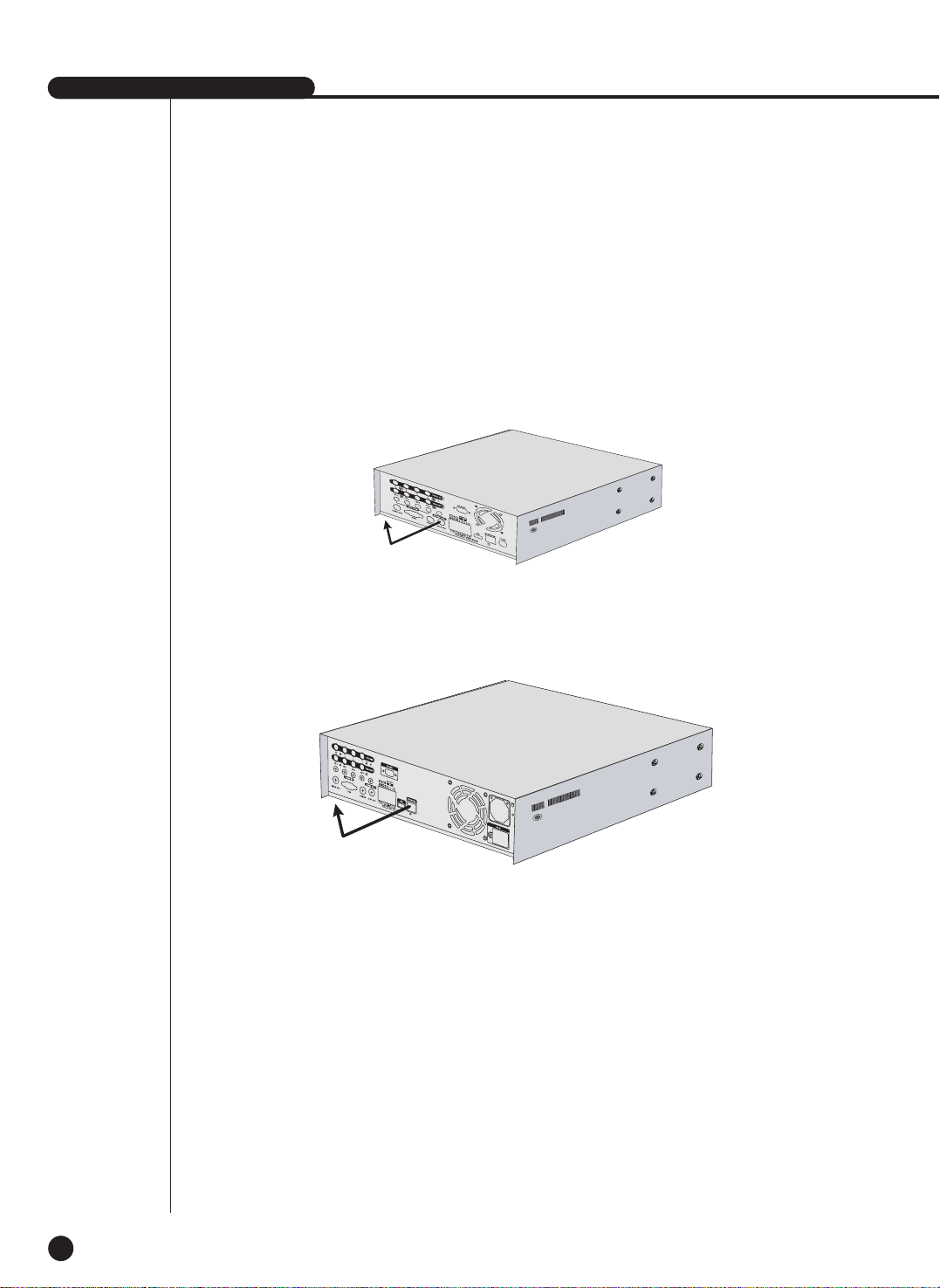
[HDD Addition Procedure]
1. Loosen screws on both sides(5 points) and back(1 point) to detach the product cover.
[SHR-2040]

2-4
[SHR-2041]
[SHR-2042]
SHR-2040/2041/2042 USER’S MANUAL
2-5
2. Detach the cover from the product. (Pull out the cover slightly and lift from the back side to
detach.)
[SHR-2040]
[SHR-2041/2042]

2-6
3. Abracket(BRACKET- HDD) is mounted to each side of product to fix the HDD. Please loosen
the screw of the bracket to which you want to fix HDD.
BRACKET-HDD

SHR-2040/2041/2042 USER’S MANUAL
2-7
4. Pull BRACKET-HDD to the product center to detach the fixed part at the bottom and detach
BRACKET-HDD from the product.
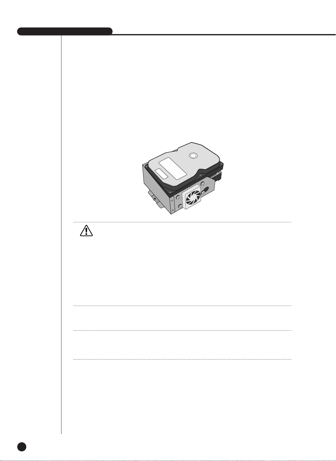
5. Tighten 4 special screws(BWH,6-32UNC,L10.5), supplied as an accessory to fix HDD to
BRACKET-HDD. (Aforce to tighten the screw shall be strong enough to resist vibration.)

2-8
7. Check if BRACKET-HDD has been fixed to the product and connect both the power supply
cable and the signal transmission cable (IDE CABLE) to the HDD.
Signal Transmission Cable
(IDE Cable)
Power Supply Cable
6. Reattach HDD to the original position of BRACKET-HDD.
(Assembly shall be done in the reverse procedure of disassembly as follows. Align the 5
fixing points at the bottom with the BRACKET-HDD fixing holes respectively and push
BRACKET-HDD out of the product to align the screw fixing holes. Then, tighten the screws
firmly.)
SHR-2040/2041/2042 USER’S MANUAL
2-9
8. Check the connector, wiring, and cable fixing condition inside the product and close the
cover.
9. Tighten cover-fixing screws. (5 points on both sides and 1 point in the back side)
✻ You can apply 2 HDDs to each BRACKET-HDD as shown in the figure.
Caution
Caution
For HDD addition, please select the same HDD with the existing HDD fixed to the product as
far as possible.
- SHR-2040 : 1 at Primary Slot and 1 at Secondary Slot respectively
- SHR-2041 : 2 at Primary Slot and 2 at Secondary Slot respectively
- SHR-2042 : 2 at Primary Slot and 1 at Secondary Slot(The internal CD-RW is connected to
the secondary master.) respectively
Both HDDs attached to Primary Slot and Secondary Slot should be set to Master and Slave
respectively. Refer to User’s Manual for Master or Slave Jumper Setting.
In the event of only one HDD installation, it shall be inserted into the Primary slot.
Note
Note
Refer to Appendix 2 to see which HDD specifications are supplied.

2-10
WARNING
! Regarding the sub fan, you need additional brackets and sub fans as follows.
The sub fan is shaped like this when viewed from the front and back. Please pay attention to
the fan direction to let wind go through the fan.
@ Fix the fan as follows

SHR-2040/2041/2042 USER’S MANUAL
2-11
# Please install the fan which is seen at the right from the front view of SHR-set as follows.

2-12
$ The cable should be out from the left hole.

Chapter 3
Connecting with
other device
3
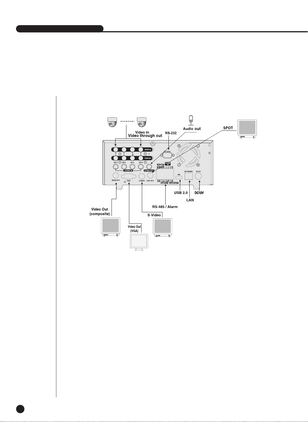
1
Connecting the Video, Audio, and Monitor
3-1
SHR-2040/2041/2042 USER’S MANUAL
[SHR-2040]

3-2
[SHR-2041/2042]
SHR-2040/2041/2042 USER’S MANUAL
3-3
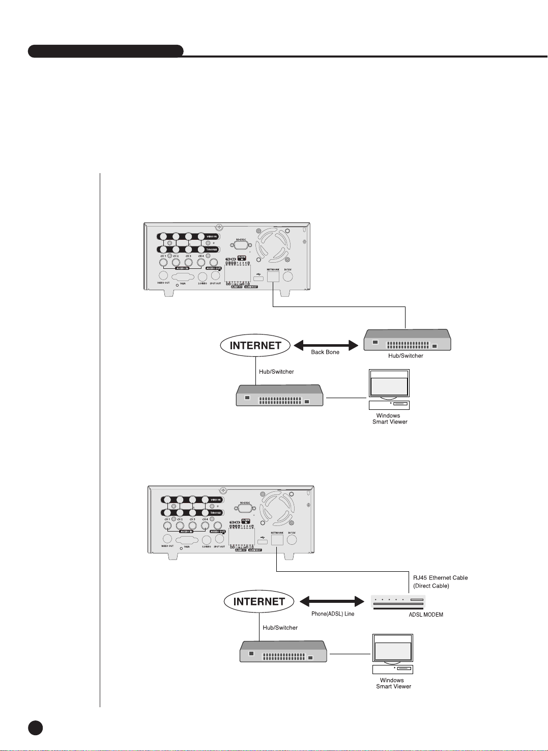
2
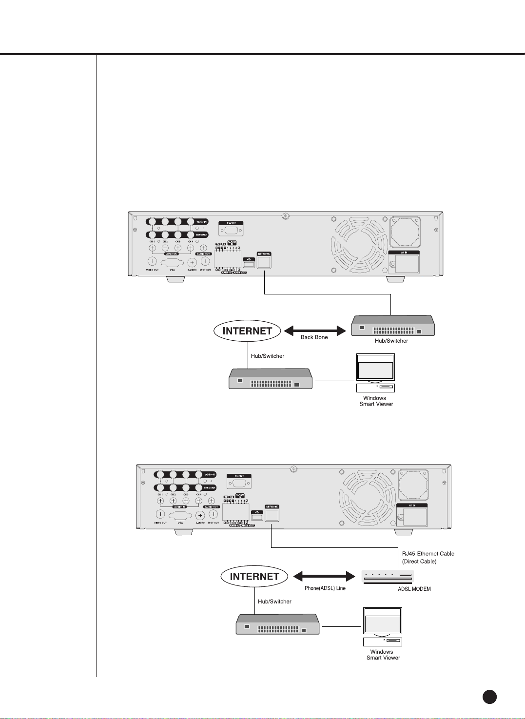
Connecting the Network
● Connecting to Internet through Ethernet(10/100BaseT)
● Connecting to Internet through ADSL
[SHR-2040]
[SHR-2040]
3-4
● Connecting to Internet through Ethernet(10/100BaseT)
● Connecting to Internet through ADSL
[SHR-2041/2042]
[SHR-2041/2042]

1. There are two USB connecting ports on the front and back of SHR-2040/2041/2042.
2. USB Hard Disk, USB CD/DVD, and USB Memory are connected through the front and back
ports of SHR-2040/2041/2042.
3. Only one USB device can be connected with each USB connecting port.
4. If the USB HDD is connected to the system, it should be detected and set through
Menu - System - HDD setup before the operation.
5. It supplies the function of HOT PLUG, which connects/removes the USB device, during the
system operation.
Caution
Caution
- Wait until the USB device connected by hot plug is stabilized enough and click CONNECT
in SHR-2040 / 2041 / 2042 MENU before use.
- USB port on the front and back of SHR-2040/2041/2042 cannot be connected to same kinds
of USB device. (For example, the case is that 2 CD-RW devices or 2 USB Memories are used
by connection with the front and back of system.)
- If you use the USB Memory on SHR-2040/2041/2042, it should be composed of the format
being supported by SHR-2040/2041/2042. Although you format it with FAT32 format on PC,
it will be re-formatted, in case of (when) connecting with SHR- 2040/2041/2042.
Caution
Caution
- The hard disk of USB device should be set to Master.
Note
Note
See 5-8 System (HDD Setup) of User’s Manual.
SHR-2040/2041/2042 USER’S MANUAL
3-5
3
Connecting the USB

3-6
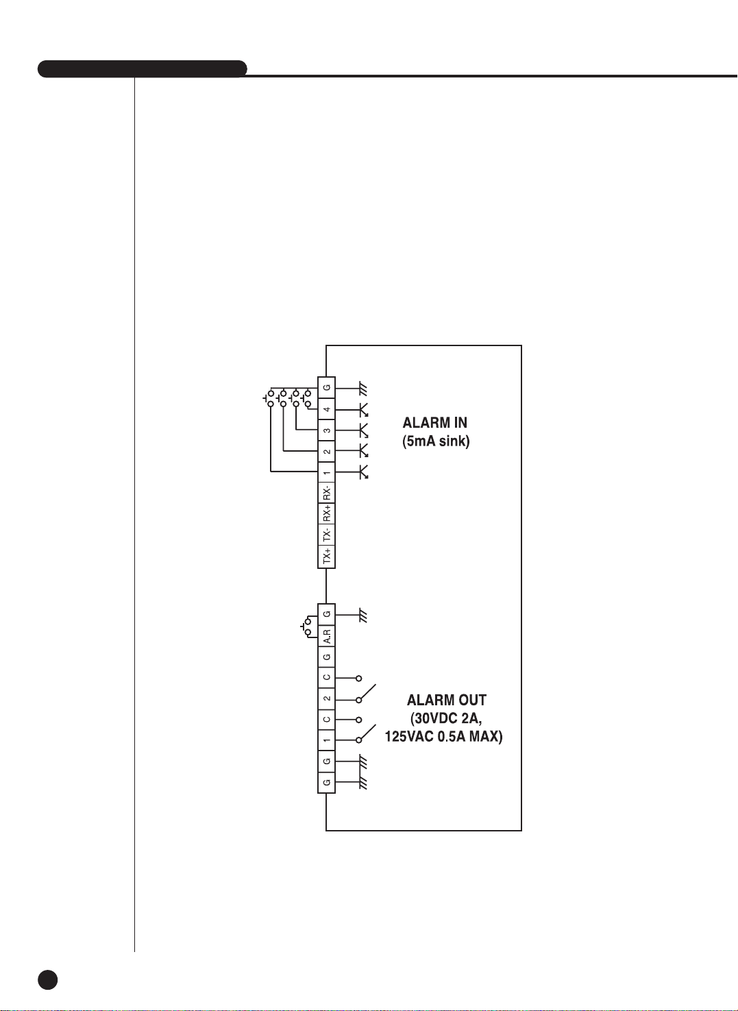
4
Connecting the Alarm Input/Output
The Alarm IN/OUT port in the back of SHR-2040/2041/2042 is composed of the following
elements.
● ALARM IN/OUT Connection
Name Function
- ALARM IN1
1 - ALARM IN2
- ALARM IN3
- ALARM IN4
2 - ALARM RESET IN
3 - ALARM OUT1
- ALARM OUT2
ALARM Input Port
ALARM Output Port
On receiving an ALARM RESET signal, the system cancels the current ALARM input and output
signal and then resumes sensing.
SHR-2040/2041/2042 USER’S MANUAL
3-7
● ALARM IN/OUT Connection
3-8
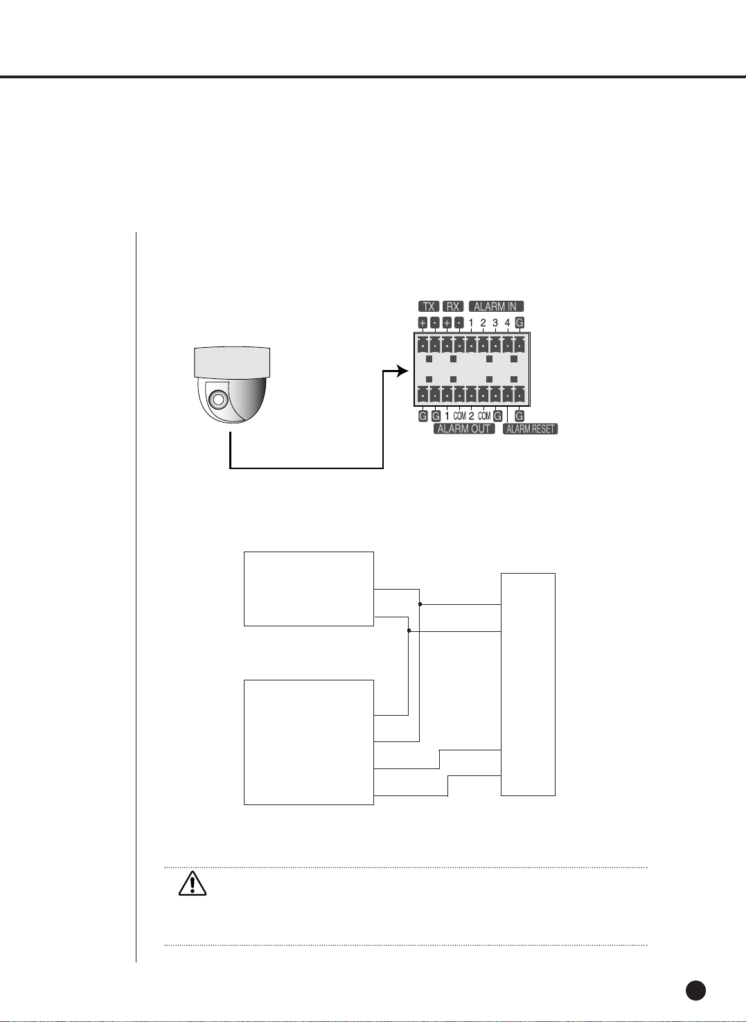
5
Connecting the RS-485 Device
● Connect the RS-485 Device through the back port of SHR- SHR-2040/2041/2042.
● You can install and control the PTZ camera supporting the RS-485 communication.
● You can adopt either Half Duplex or Full Duplex method for the connection.
● Baud Rate supports 600/1200/2400/4800/9600/19200/38400.
Half Duplex Type
Data (–)
Data (+)
Full Duplex Type
Rx(+)
Rx(–)
Tx(–)
Tx(+)
Tx(–)
Tx(+)
Rx(–)
Rx(+)
PTZ device SHR-2040/2041/2042
Rear
Caution
Caution
Check if RS-485 device is compatible with SHR-2040/2041/2042 first. Then pay attention not
to change the polarity(+, -) of RS-485 when connecting it.

Chapter 4
Live
4

1
System Operation
4-1
SHR-2040/2041/2042 USER’S MANUAL
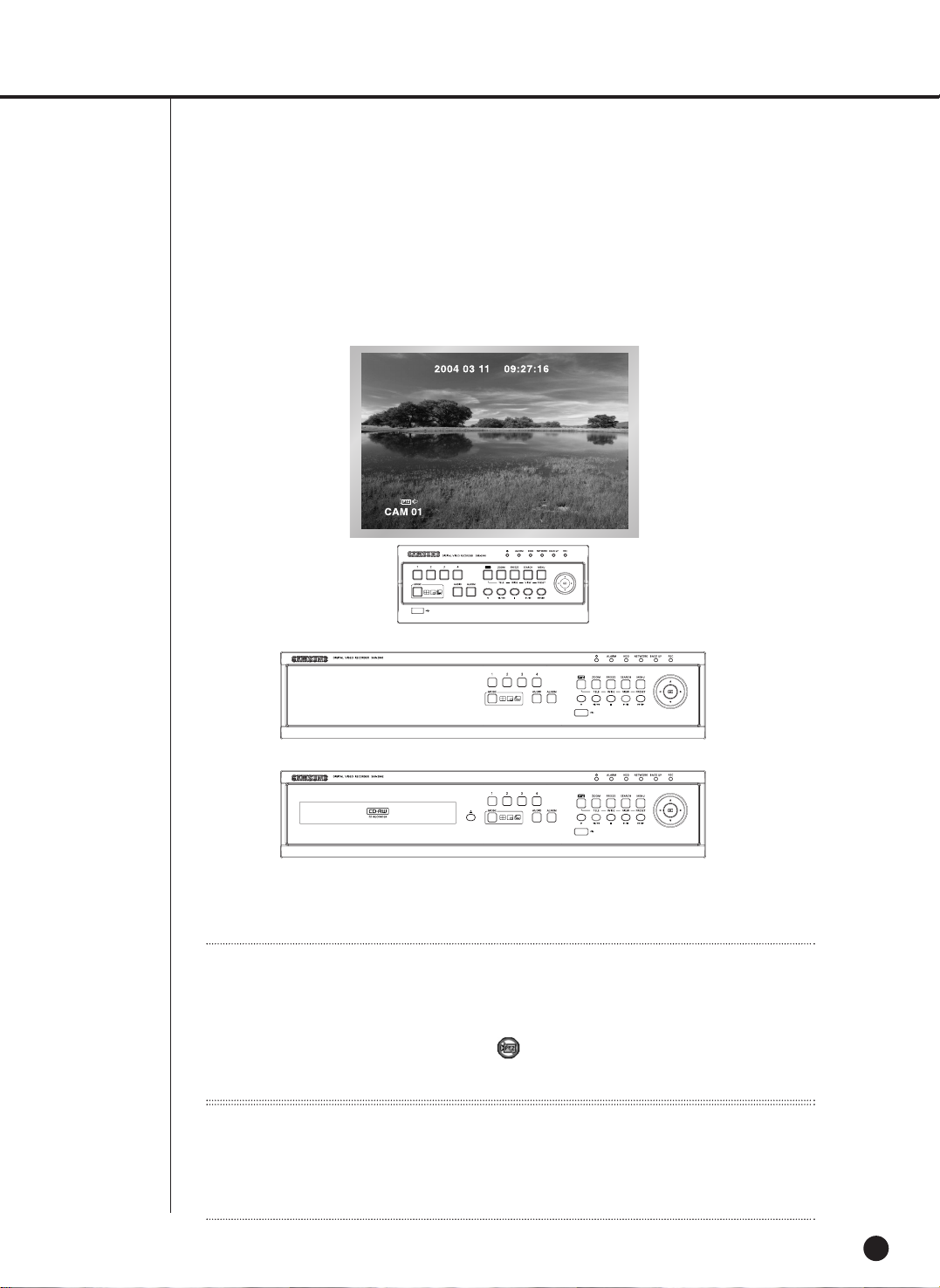
● Turn the power on and the following LOGO pops up on the screen.
● After the LOGO appears, all of LED in the front flickers 6 times to initialize the system for
operation.
● Upon completion of normal initialization, the Live screen appears accompanying a beep
sound.
● It requires 30 to 40 seconds until the Live screen appears.
Note
Note
If a new HDD is installed, it may require more time to be appeared the Live screen due to the
initialization time of a new HDD.
If the Live screen does not appear continuously or the LED in front repeats flickering, please
check the connection between inside and outside. If the system does not operate in normal,
contact with the shop where you bought the product.
Note
Note
If the Live screen dose not appear, check if the Video Out comes out in Composite mode or
VGA mode.
● The Live screen does not affect the earlier MENU setup. If you reboot the system
after power-off during recording, the Live screen will appear, accompanying recording.
2
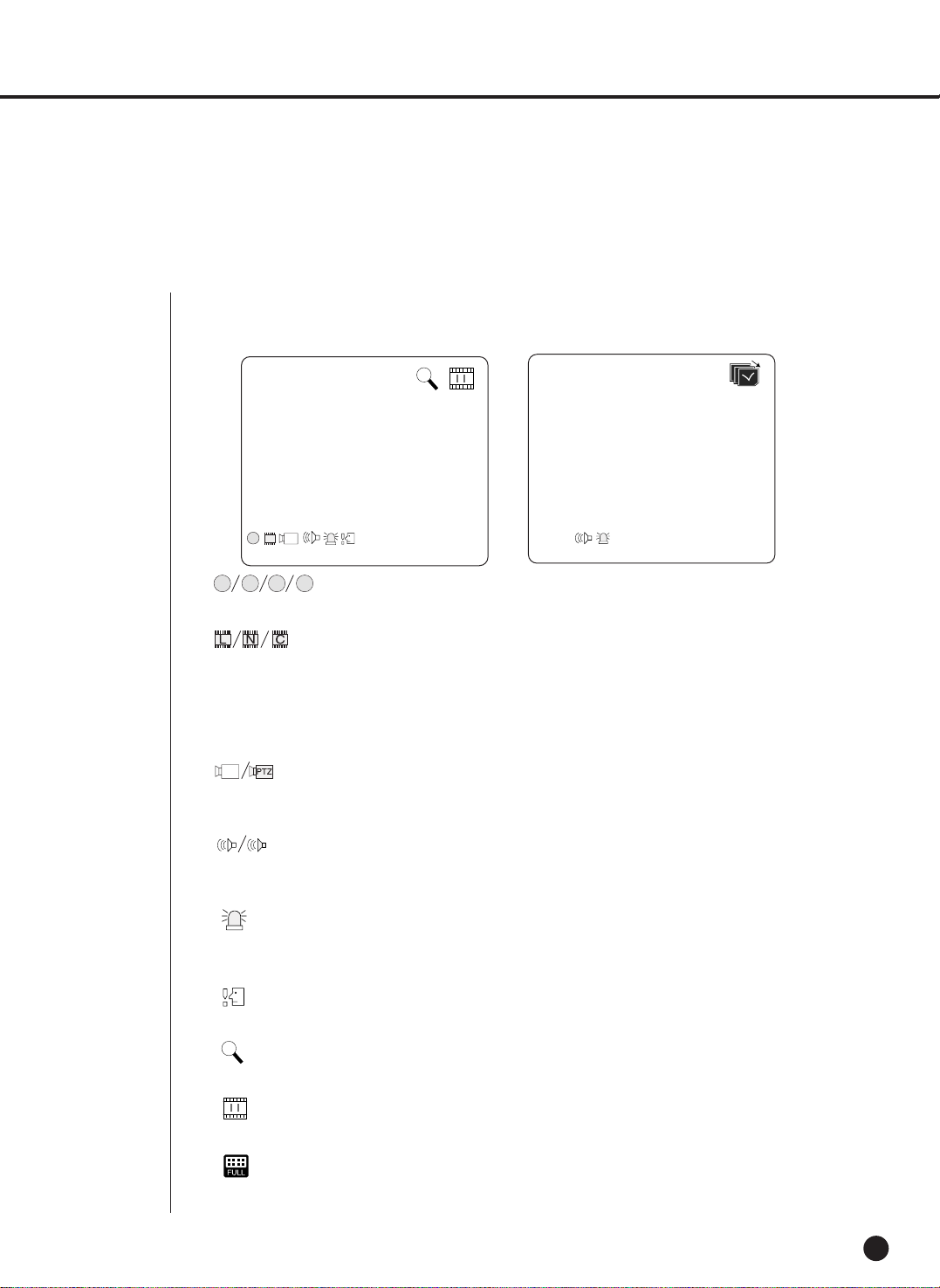
Live screen Mode
4-2
Definition of Live Screen Icon
The Live screen icons display the current setup and function status of each screen.
PTZ
N
CAM_01
CAM_01
V.Loss
: Recording Icon
Each icon represents Normal / Event (Alarm + Motion) / Schedule Recording.
: Recording Video Size Icon
Each icon represents the recording size of Large / Normal / CIF.
- Large : Full D1 - (NTSC) 720X480 (PAL) 720X576
- Normal : Half D1 - (NTSC)720X240 (PAL) 720X288
- CIF : CIF - (NTSC)352X240 (PAL)352X288
(Full D1 is supported only when “1 CH DVR support”)
: PTZ Icon
This icon appears when setting the PTZ device with the PTZ icon and changes to yellow color
when operating the PTZ.
: Audio Icon
This icon represents the Audio On/Off status and changes to yellow color at the Audio On. It
does not appear in the Video mode or Audio Disable.
: Sensor In Event Icon
This icon appears in the channel linked with the external sensor signal when inputting the signal
at the Sensor On.
: Motion Event Icon
This icon appears in the Motion Event channel at the Motion Detection On.
: Zoom Icon
This icon appears at the Zoom On or Zoom In and disappears when canceling the Zoom On.
: Freeze Icon
This icon appears in the Freeze mode and disappears when canceling the Freeze.
: HDD Recording Disk Full Icon
This icon appears when the recording space is full in the HDD.
P ES
PTZ

SHR-2040/2041/2042 USER’S MANUAL
4-3
Definition of Live Screen Mode
The system receives 3 live images and displays them in the following 3 modes.
● 4 Split Mode:
Four channels are split in the screen separately.
You are able to choose a channel as you want to in each split mode.
● PIP(Picture In Picture) Mode:
Displays a one-fourth sized screen in the full screen. You are able to choose a channel as
you want to, which is displayed in the full screen and reduced screen area. You may move
the PIP screen at 5 stages in the Full screen with the ,key.
● Auto sequence Mode:
Displays the full screen of each channel in sequence according to the setup time.
CAM_01
CAM_02
PIP Mode Auto sequence Mode
CAM_03
CAM_04
CAM_01
CAM_02
4 Split Mode
: Auto sequence Icon
This icon appears in the auto sequence mode.
: Backup Playback Icon
This icon appears when the backup data is played.
: Fan Error Icon
This icon appears when the fan stops.
: This icon appears when there is no HDD.
V.Loss / V.Off : Video Input Status
If there is no more video data input in the Video On, [V.Loss] appears in the channel.
If you set Video On/Off to Off, [V.Off] will appear.
➞➞

4-4
Selecting Live Screen Mode
Each mode may be selected by [MODE Button] and [CH1 ~ CH4 Button].
The following figure shows Live Mode after converted.
● The default setup is 4 Split Screen Mode.
● You are able to choose other modes than Full Screen Mode by the [MODE] button in
sequence. Whenever you press the [MODE] button, the system will change
[4Split]➝[PIP]➝[auto sequence]➝[4 Split] in sequence.
● If you press [CH1~CH4 button], you will be able to see the full screen of each channel.
● The MODE button is used to return to the previous split mode screen from a full screen
mode.

3
Live Channel Selection and Audio On/Off Setup
In other split modes than Full Screen Mode and Auto Sequence Mode, you can choose a channel
to be displayed in each split area on your own. In addition, the channel being set to Audio On can
be set to Audio On/Off in all Live Modes.
Audio On/Off Setup in the Full Screen
In the Full Screen Mode, the selected channel Audio is automatically turned on and you can set
up Audio On/Off with toggling the channel button. Depending on the Audio On/Off setup
condition, the Audio icon of the channel changes to the Yellow/white color.
Audio On/Off Setup in the 4 Split Mode
If you press [ENTER] Button in the 4 Split Mode, the selection cursor in the following figure
will appear and the channel concerned will be selected. If you press the Audio button in the status
of being selected a channel, you can set Audio On/Off for the channel concerned. Depending on
the Audio On/Off setup condition, the Audio icon of the channel changes to the Yellow/white color.
SHR-2040/2041/2042 USER’S MANUAL
4-5
Channel Selection and Audio On/Off Setup in the PIP Mode
As in the 4 Split Mode, if you press [ENTER] button in the PIP Mode, the selection cursor appears
and the concerned channel is selected. With being selected a channel, you can select a channel
on the current screen by the [CH1 ~ CH4] button and set Audio On/Off by the Audio button as in
the 4 Split Mode. Depending on the Audio On/Off setup condition, the Audio icon of the channel
changes to the Yellow/white color.
CAM_03 CAM_04
CAM_01 CAM_02
Note
Note
Audio On/Off of 4 split mode cannot be set in the playback screen.

4-6
4
Freeze and Zoom
Freeze Function
Freeze function pauses the video image in the Live Screen, it is only available in the Live Mode.
You can set Freeze On/Off with [FREEZE] Button and [FREEZE LED] is turned on or off
depending on the Freeze On/Off setup condition.
Zoom Function
Zoom function enlarges the selected area to double size, and it is only available in the
single mode.
If the [ZOOM] button is pressed in the single mode, the Zoom area appears. Use the
UP/DOWN/LEFT/RIGHT key to adjust the position of Zoom area. After selecting the Zoom area,
press the [Enter] button to display the selection area in double size. You can adjust the video
image position with the UP/DOWN/LEFT/RIGHT key at the Zoom in state. For Zoom off at the
Zoom in state, use the [ZOOM] button.
[ZOOM LED] is turned on or off depending on the Zoom On/Off setup condition.

5
Event Monitoring
Event monitoring displays the channel synchronized with a event on the screen when a special
event (Sensor/Motion/Video Loss) occurs. Event monitoring On/Off and event duration setup is
available in [Menu]➝[Monitoring] mode.
If you set the event monitoring interval to 5 seconds and an event occurs at CH2 in
the beginning as following figure, the system will display CH2 in the full screen for 5 second.
If another event occurs within 5 seconds, it is displayed together with the existing event. As the
following figure, both CH1 and CH3 events occur within 5 seconds (for example, after 4
seconds) after occurring CH2 event, these three events are split into 4 screens.
If the new event does not occurs during the event duration, the system will return to the
previous Live mode. Pressing the [ALARM] button during the event duration makes the event
monitoring stop. On occurring an event, [ALARM LED] is turned on. Press the [ALARM] button
to turn [ALARM LED] off.
The alarm setup is initialized and the event icon disappears, and the event monitoring is off if it
is on when pressing the [ALARM] button. After alarming, the event recording is continued again
for set time.
SHR-2040/2041/2042 USER’S MANUAL
4-7
Note
Note
The Alarm LED does not turn off even though the event recording is finished. To turn the
Alarm LED off, press the [ALARM] button.

4-8
6
Spot-out monitoring
Spot-out Monitoring has nothing to do with Live Screen Output, it monitors the full screen of a
certain channel. If you select the Monitoring in the MENU, the one channel among CH1 ~ CH4
is output with a Spot-out or channels are output one by one at an interval as Auto Sequence
Mode in the Live Mode. Live screen icon does not appear in the spot-out monitoring.
The interval is as same as the Auto Sequence time in the Live Mode. If the Spot-out Event
Monitoring is On, it is possible to see the event channel with Spot-out. In case of simultaneous
event occurrence at more than one channel, the lowest numbered event channel has the first
priority to be spotted out.
Caution
Caution
If the built-in HDD is not connected, or it operates with power applying in error,(
)
indicating "built-in HDD error" is displayed at the top of left.
At this time,
(1) Live screen mode
(2) Monitoring mode by Smart Viewer
operate only and the other functions including recording, search, playback, menu
setup, and PTZ do not operate.
If the above problem is occurred, be sure to contact a service center to settle the problem.
Caution
Caution
If the fan in a set does not operate or has a problem, a fan error message pops up in the live
screen as below picture. And the fan error icon appears at the top of left . If it is, check
the fan in the set. The icon at the top of left disappears automatically if the fan recovers its
operation.
Fan Information
A error occurs in the fan.
Refer to the manual.

Chapter 5
Menu Setup
5

Before Use
5-1
● Selection
The yellow cursor shows the current window. Use the ,,¦, key in the front to move
the cursor on your desirous menu. If you press the “Enter” key with the cursor clicking on
your desirable menu, the system will enter the new mode.
Press the “Enter” key to finish the selection. On seeing Drop Down Menu, use the or
key to move the cursor on your desirable menu.
● “OK” or “Cancel” in Menu Setup Window
Once changed, the new menu setup procedure will be finalized by pressing “OK”.
Pressing “Cancel” will cancel the new setup and return to the upper menu.
● Front “MENU” and “SEARCH” Button
The MENU button or SEARCH button, if pressed first, acts as an entrance button.
Once entering, it reverses the page to the previous one.
● The “>” or “V” mark beside the title copies the line in the arrow direction to the value of the
first line.
● The first page of the menu is structured as follows.
SHR-2040/2041/2042 USER’S MANUAL
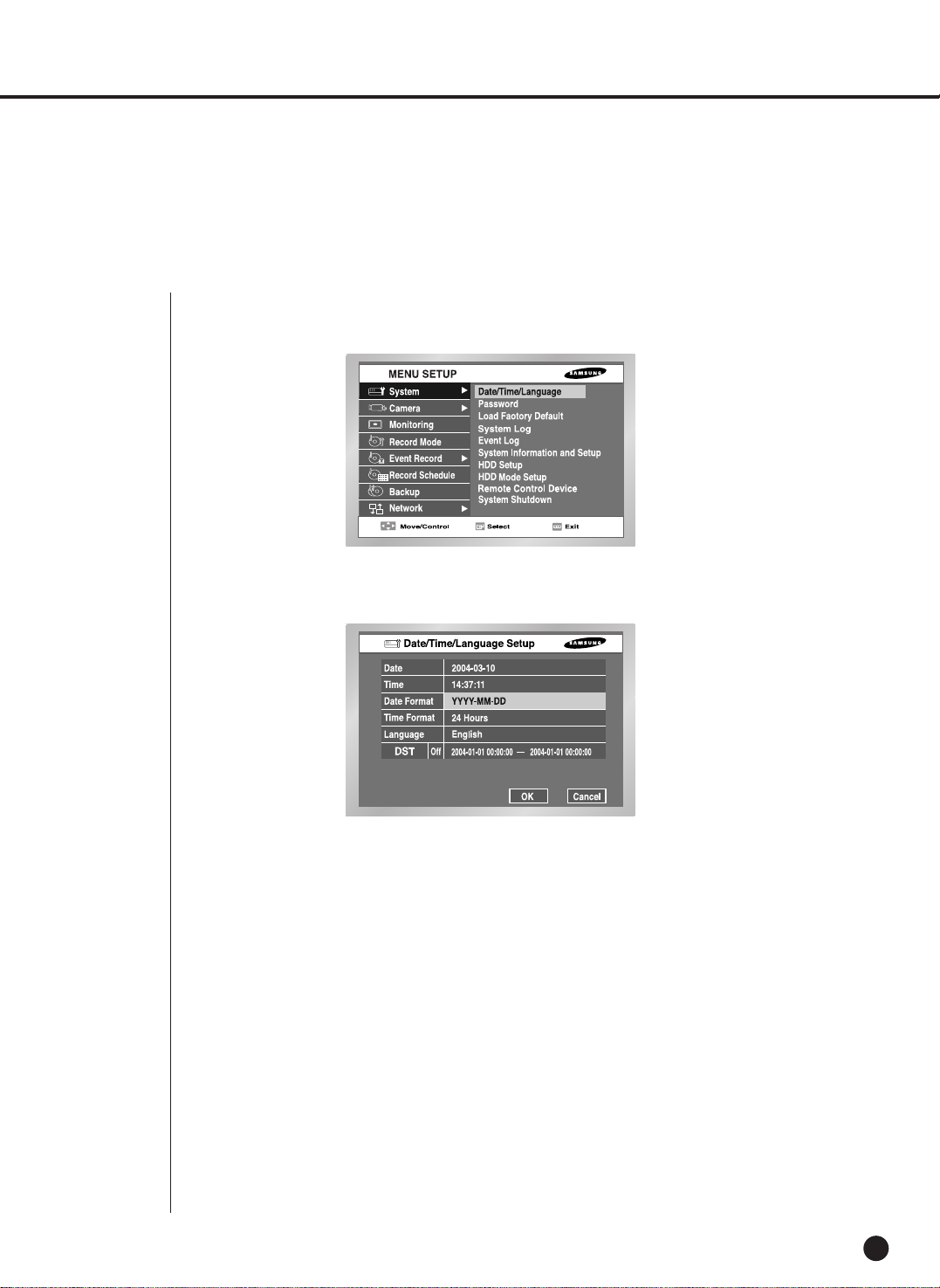
1
System
5-2
● System Menu has the following items in detail.
● Press the “Enter” key and the ¦, key to move to Y/M/D.
Use the , key to change the date.
Press the “Enter” key to come out of the mode.
● Time
Press the “Enter” key and the ¦, key to move to H/M/S.
Use the ¦, key to change the time.
Press the “Enter” key to come out of the mode.
● Once changed, the date and time will remain unchanged until you press “OK” or
“Cancel”.
Date/Time/Language Setup
SHR-2040/2041/2042 USER’S MANUAL
5-3
● Date Format
The system supports 3 formats, YYYY-MM-DD / DD-MM-YYYY / MM-DD-YYYY.
● Time Format
The system supports 2 formats, 24 Hour / 12 Hour(AM/PM).
● Language
After selecting a language, OSD is expressed in the selected language.
The available language is added in the list.
● DST(Daylight Saving Time)
DST sets the watch one hour faster than the local standard time. This menu
makes the system count for DST in DST regions. The system goes one hour faster
and reboots at the setup date.
If the DST is Off, it does not operate. And it is impossible to enter the right date
menu. To setting the DST, enter the start time on the left and the end time on the
right of ‘~’. DST is allowed to set Month/Date/Time only.
Year/Minute/Second remains inactivated.
Note
Note
[Date/Time Change]
Pressing “OK” after you change date and time, you will be asked by a pop-up window
if you really confirm the change. Here, press ”Yes” to change the time. Since Date/Time does
not change in backup process, be sure to stop the backup process before you change
Date/Time. If the date or time is changed, the system reboots.
Note
Note
[On DST Setup]
Backup in progress will be cancelled. Recording in progress will be suspended for a moment
until rebooting.
Caution
Caution
[Date/Time Change]
If the Date/Time changes to the original value, the data recorded before the change may be
deleted. For example, if the time is changed from 8 am to 7 am, all the data recorded between
7 am and 8 am will be deleted.
Caution
Caution
[On DST Operation]
As the system goes one hour earlier, the data recorded since an hour ago will be deleted.
As DST activates at the preset time, you are recommended to take the utmost care of
preventing any trouble incurred by data deletion or rebooting.
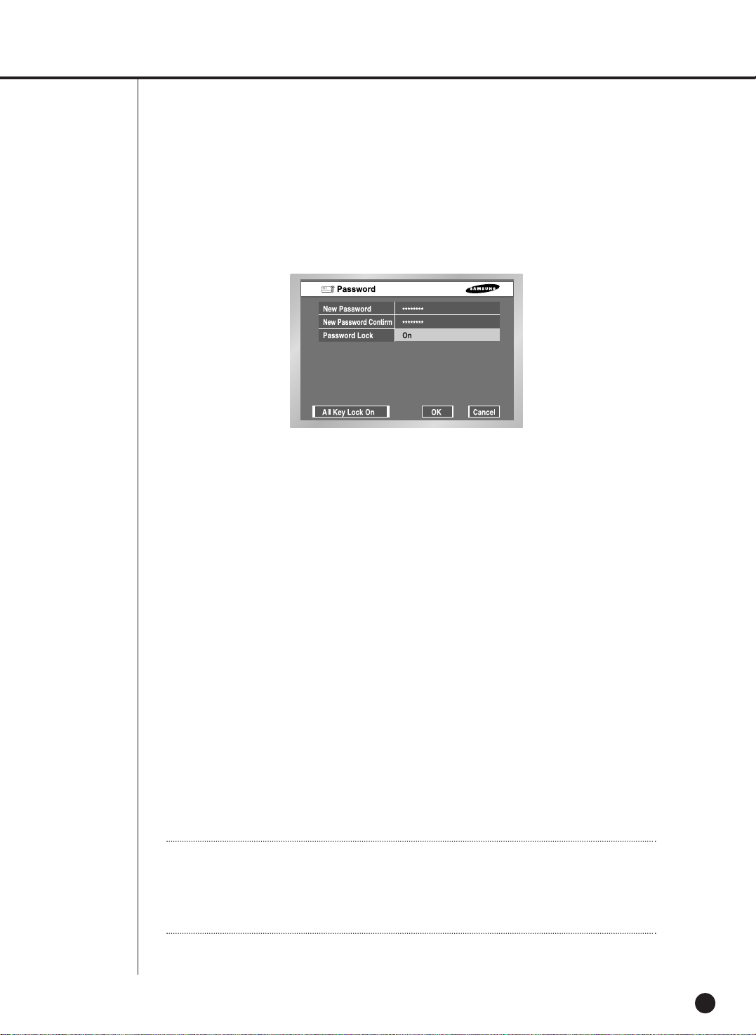
5-4
Password
● The Default Password is 4321.
● New Password
This is used to change the system password inside SHR-2040/2041/2042. You are
allowed to create a password up to 4 digits. Press the “Enter” key and a channel
button from 1 ~ 4 at the left. Press the “Enter” key after change to move to “New
Password Confirm”.
● New Password Confirm
This confirms a new password. You shall be obliged to input New Password in
the above row first. Without New Password input, New Password Confirm input
has no effect.
● Password Setup
If it is set to On, a window for asking the password pops up when pressing the
menu button.
If it is set to Off, you are allowed to enter the menu mode without being asking the
password when you press the menu button.
● All Key Lock On
If you select this, the system will enter the Live Mode immediately. If you press any
button in the front, the Password window will pop up. If the correct password is
input, the lock function is cancelled after popping up a message for the
cancellation of Key Lock.
Note
Note
[All Key Lock On]
If you select this, the system will change to the Live Mode immediately and keys will be
locked.
SHR-2040/2041/2042 USER’S MANUAL
5-5
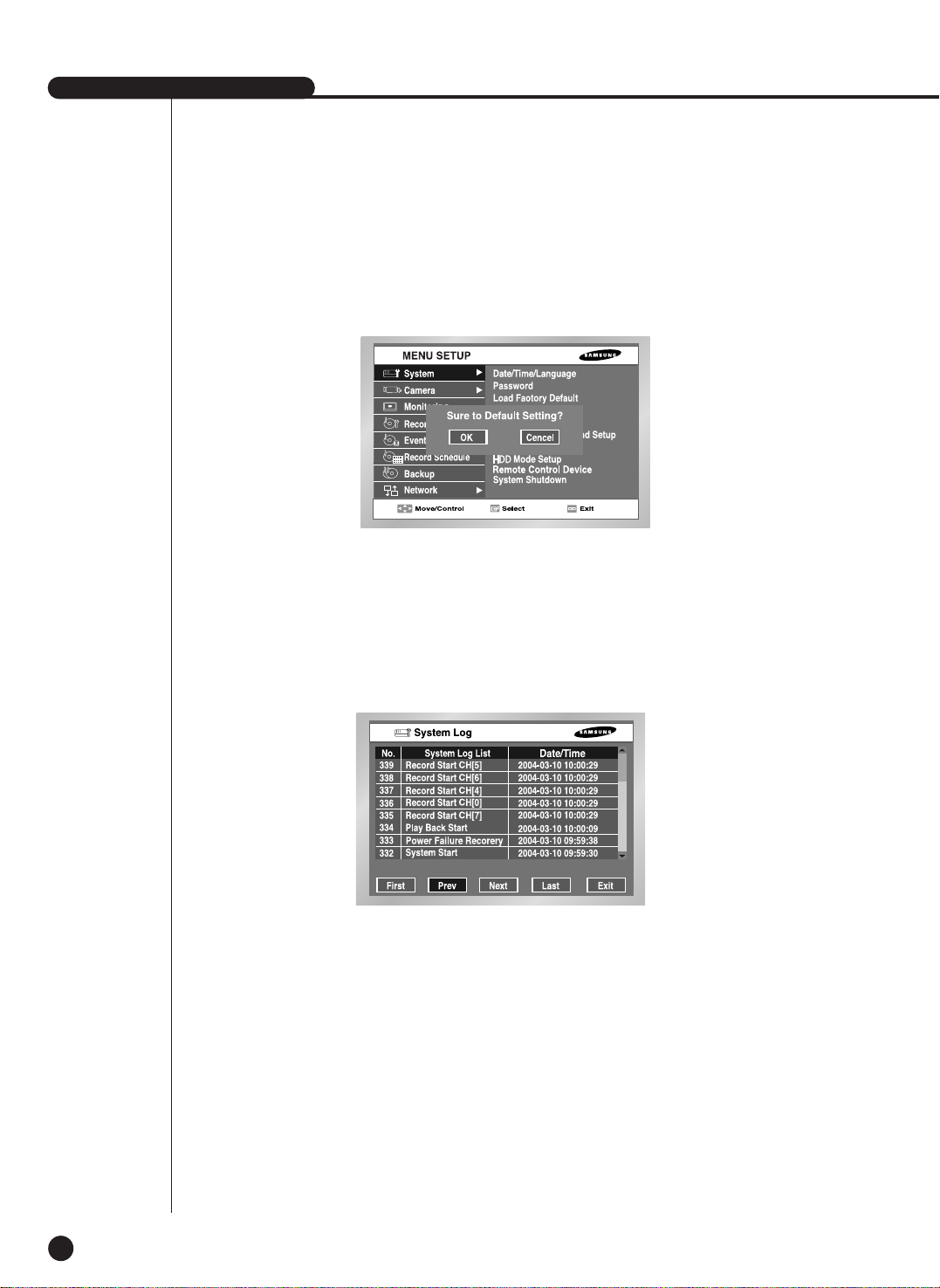
Load Factory Default
● It used to initialize all the menu setup values. The recorded data will not be deleted.
Press “OK” in the confirmation window to start initializing.
System Log
● System Log is used to check the important record by an administrator.
● It displays such contents of a system related log and its execution date/time as System
Start, System Termination, and Menu Setup Change.
● First : Moves to the first Log page.
● Prev : Moves to the previous Log page.
● Next : Moves to the next Log page.
● Last : Moves to the recent Log page.

5-6
● System Log List
Event Log
● It used to check the record regarding Event like Alarm / Motion / Video Loss.
● It displays the contents of a log regarding event and its execution date / time.
● First : Returns to the first Log page.
● Prev : Back to the previous Log page.
● Next : Forwards to the next Log page.
● Last : Moves to the recent Log.
● Event Log List
Video Loss CH[N] Means the occurrence of Channel [N] Video Loss.
Alarm Detection CH[N] Means the occurrence of Channel [N] alarm.
Motion Detection CH[N] Means the occurrence of Channel [N] Motion.
System Start Starts the system.
Login(Admin) Viewer Login (Admin)
Logout(Admin) Viewer Logout (Admin)
Login(User) Viewer Login (User)
Logout(User) Viewer Logout (User)
Setup Start (Local) Set Enters into the menu.
Setup End (Local) Set Comes out of menu.
Setup (Remote): Viewer Sets the menu.
Play Back Start Starts the playback.
Play Back End Ends the playback.
Record Start CH[N]
Starts the Channel [n] recording
.
Record End CH[N]
Ends the channel [n] recording.
Power Failure Recovery
Returns the system after power interruption.
Time Change Changes the Date/Time.
Load Factory Default Initializes the system.
System Upgrade
Changes the system S/W.
Disk Full No Space in the HDD
Backup Start Starts the backup.
Backup End Ends the backup.
Backup Stop Stops the backup.
Backup Fail Backup Failure
ATA HDD Erase Erases the ATA Data.
USB HDD Erase
Erases the USB HDD data.
USB MEMORY Erase
Erases the USB MEMORY data.
Overwrite Playback Stop
Stops the playback by overwrite.
Backup Stop(Overwrite)
Stops the backup by overwrite.
SHR-2040/2041/2042 USER’S MANUAL
5-7
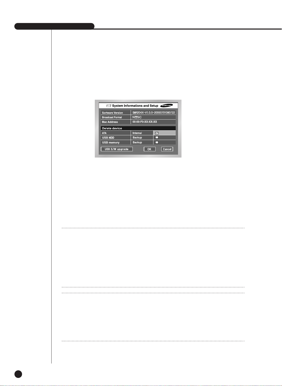
System Information and Setup
● Software Version
: Displays the current version. Setup is not available.
● Broadcast Format
: Displays the current Format(NTSC/PAL) . Setup is not available.
● Mac Address : 6 Byte hardware address. Setup is not available.
● Device Erase
This erases the data in ATA / USB HDD / USB memory. Click the checkbox of the device
that you want to erase and press “OK” You are not allowed to erase the data in Backup
progress.
● USB S/W Upgrade
You can update the program by use of USB device. If there is no device, "USB S/W
Upgrade fail" window pops up.
Note 1
Note 1
[Internal HDD]
This is a physical hard disk connected with the IDE cable inside the SHR2040/2041/2042 main body, and
stores data.
[External HDD]
This is a physical hard disk connected with the port and terminal in the back of the
SHR2040/2041/2042 main body, and stores data.
This can be used as Extended HDD or Backup HDD.
- Extended HDD : Supplements Internal HDD quantity. Connected, it takes the place
of Internal HDD.
- Backup HDD : Backs up the data recorded in the set.
Note 2
Note 2
[ATA]
Usage : Internal HDD
This is a physical hard disk connected with the IDE cable inside the SHR2040/2041/2042 main body.
[USB]
Usage : External HDD(Extended HDD or Backup HDD)
This is a physical hard disk connected with the USB port in the back of the SHR SHR2040/2041/2042
main body,

5-8
HDD Setup
● HDD Information
Displays the number, capacity, and status of ATA and USB device. Setup is not available.
Status : Internal HDD, External HDD, Backup HDD
● External HDD Setup
1. Backup/External type
You are able to determine the usage of USB.
Not Defined ➝ Appears when the usage of connected HDD is not defined.
You can set to External or Backup type.
No Device ➝ Appears when there is no HDD connected. You are able to connect it by
pressing the right connection TAB after connecting HDD
External ➝ Appears when the connected HDD is set to External type. It may used as a
backup HDD if you press the “Enter” key and turn to Backup.
Backup ➝ Appears when the connected HDD is set to Backup. If you press the “Enter”
key and turn to External(Extend), it can be used as an External HDD.
Caution
Caution
[Device Erase]
Data will not be deleted in the backup mode.
Please be sure to stop the backup before you delete a data. In the recording mode, suspend
the recording and delete a data.
Caution
Caution
[USB S/W Upgrade]
Download the software to upgrade at http://www.sec.co.kr, CCTV Part.
If the USB memory to upgrade has a format not being supported by DVR set, the upgrade is
impossible.
In this case, use the “device erase” of menu 5-7 system information and setup.
Only one file to upgrade is allowed in the USB Memory.

SHR-2040/2041/2042 USER’S MANUAL
5-9
HDD Mode Setup
● HDD End Mode
Stop : Stops recording when HDD is full during the recording.
Overwrite : Deletes the original data and save a new data when HDD is full during the
recording.
● HDD End Beep
On : Beeps when the HDD is full in the recording mode.
Off : Although the HDD is full in the recording mode, the beep sound is not heard.
Note
Note
If the HDD is full, the Disk Full Icon( ) is appeared.
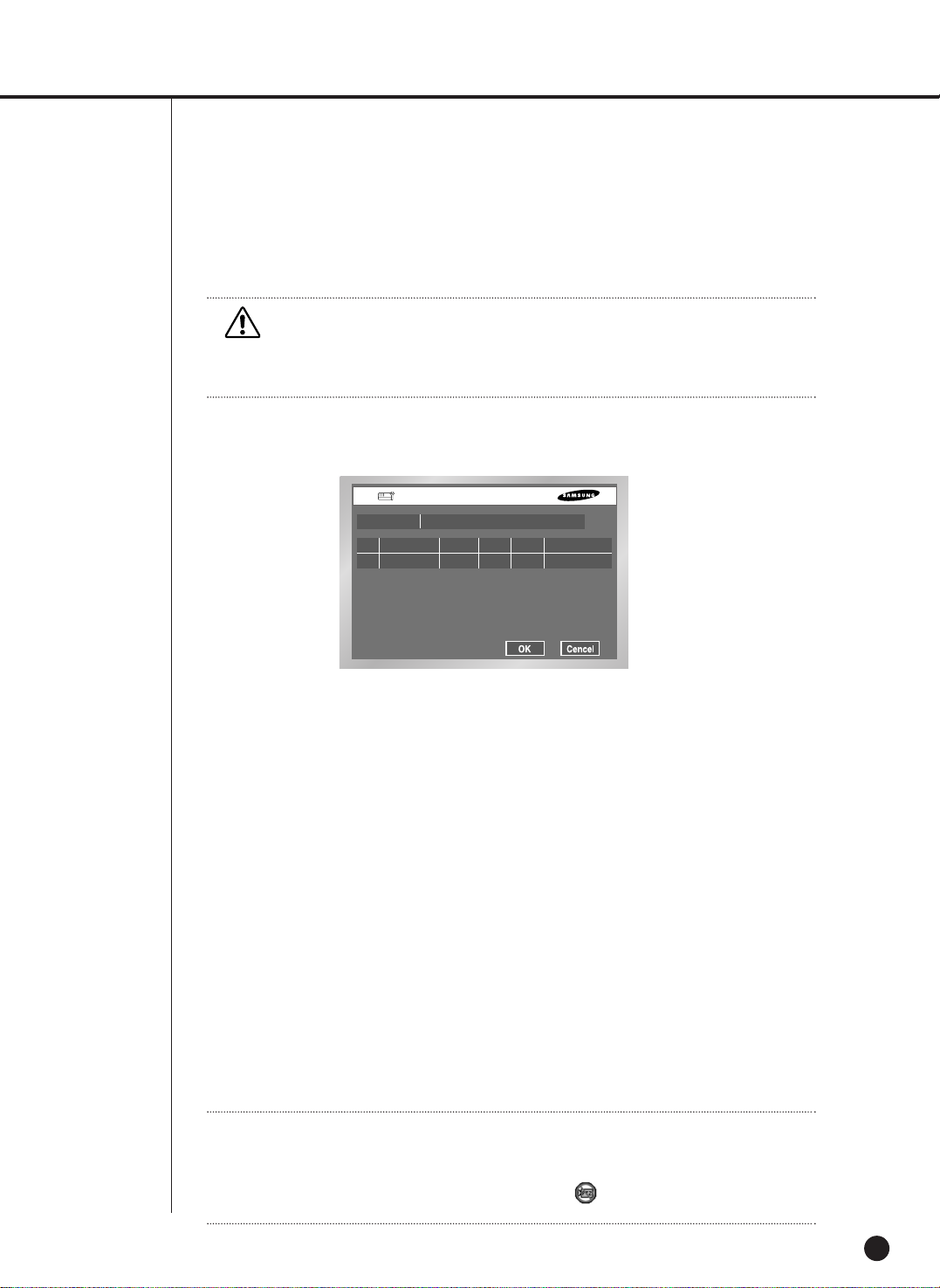
5-10
Remote control Device
● MENU for the use of Samsung system keyboard
Remote Control Device
ID Baudrate
Device Samsung System Keybord
Parity Date Stop Duplex
03 4800 None 8 1 Half Duplex
● Device
A Remote Control Device, being connected to the RS485 port.
● ID
This is a private ID of SHR-2040/2041/2042.
This private ID is essential for SSC-2000 because SSC-2000 can control many
SHR-2040/2041/2042 DVRs.
● Baudrate
Baudrate to communicate with SSC-2000
It should be same to SSC-2000 Baudrate for communication.
● Parity
Sets up one of None / Even / Odd.
● Data
Sets up either 7 or 8.
● Stop
Sets up either 1 or 2.
● Duplex
Sets up either Half Duplex or Full Duplex.
Caution
Caution
[Disk Overwrite]
In the overwrite Mode, the previous Event data is deleted and the mode is changed.
Note
Note
If you select Remote Control Device, you cannot control the PTZ device with
SHR-2040/2041/2042. The PTZ button in the front of SHR-2040/2041/2042 becomes
inactivated. Press the PTZ button and the PTZ ban icon( ) will appear. It’s because the
RS-485 port setup was done for Remote Control Device.

SHR-2040/2041/2042 USER’S MANUAL
5-11
System Shutdown
● Terminates the work in action safely and turns the power off. Press “OK” in the confirmation
window and plug out when you see “Safe to Power Off”.
Remote Control Device
Caution
Caution
[System Shutdown]
Power-off without terminating the system in the System Shutdown menu may incur
improper motion like data loss and disk failure. Power-off shall be done in the System
Shutdown menu.

5-12
2
Camera
● The detailed Camera Menu items are as follows.
● Video
On : Camera images from a selected channel appear.
Off : Camera images from a selected channel disappear.
Covert1 : Displays the information except for the Video information of selected channel.
Covert2 : Does not display the any information.
Audio/Cam name/Auto sequence setup are impossible in the Off channel.
● Audio
On : Makes the sound of selected channel on.
Off : Makes the sound of selected channel off.
Camera Config.

● Title
You can name the camera of selected channel.
If you press the [Enter] key, the Virtual keyboard will come out.
Virtual Keyboard
If you move the cursor, you can type text by text.
Up to 15 texts can be typed.
Keyboard cannot be composed of all spaces.
Pressing Caps Lock changes the keyboard that can be selected. (2 Modes)
SHR-2040/2041/2042 USER’S MANUAL
5-13
● Auto Sequence
You are allowed to set the duration of each channel at the Auto Sequence channel in the
Live Mode.
A channel, set to Off, does not operate in the Auto Sequence Mode.

5-14
PTZ Device
● ID
It is an ID for PTZ Camera and available to set from 0 to 255.
● Protocol
It is supported by the PTZ device.
The following protocols are now being supported.
Samsung / Vic. / Pan. / AD / Phi. / Ern. / Pel-D / Pel-P / Vcl. / Dia. / Kal.
● Baurate
Baurate is supported by the PTZ device. 600/ 1200/ 2400/ 4800/ 9600/ 19200/ 38400
● Parity
It is set to the one of None, Even, and Odd.
● Data
It is set to either 7 or 8.
● Stop
It is set to either 1 or 2.
● Duplex
It is set to either Half Duplex or Full Duplex.
Caution
Caution
The above items shall be same to the PTZ device setup.
For the details, please refer to User Manual of the PTZ device manufacturer.

Screen Setup
SHR-2040/2041/2042 USER’S MANUAL
5-15
● It is a window to set Brightness/Contrast/Color for the camera image of each channel.
Put the cursor on the channel that you want to adjust and set Brightness/Contrast/Color.
Once selected, the channel appears in the right PIP area. Use the or button to adjust
the value from 0 to 100.
● If you mark ✓ in the select CH, all the channel values will become the same as the finally
selected channel value.
● “Default value” resets the current channel to the basic value of 50.

5-16
3
Monitoring
● Event Monitoring
It is possible to set to Off/3sec/5sec/10sec/20sec/30sec/Continuous.
① Off : Event Monitoring does not operate to turn to the screen where an event occurs.
➁ 3sec / 5sec / 10sec / 20sec / 30sec : Sets the duration time of screen in the Auto
Sequence mode.
➂ Continuous : The Event Monitoring screen remains alive until you press the “Alarm”
button in the front to cancel the screen manually.
● OSG Display
① Date :
The date is displayed on the screen when it is On, and not displayed when it is Off.
➁ Time :
The time is displayed on the screen when it is On, and not displayed when it is Off
.
➂ Cam name : The Cam name is displayed on the screen when it is on, and not displayed
when it is off.
➃ Status :
Audio/Ptz is displayed on the screen when it is on, and not displayed when it is off.
● Spot Out Channel
Spot Out channel is used to let one of two monitors monitor a channel, focusing on it.
Spot Out channel supplies two functions, continuous monitoring of only one channel and
Auto Sequence to display all the channels one by one.
① Auto Sequence setup ranges from Ch1 to Ch 4.
➁ In the Auto Sequence mode, Spot Out channels are displayed in turn.
➂ Duration time for Auto Sequence is as same as set for Camera setup.
● Spot Out Event Monitor
Sets if event monitoring will be executed for Spot Out channels.
① Off : The event monitoring dose not operate in the Spot Out channel.
➁ 3sec / 5sec / 10sec / 20sec / 30sec : Sets the duration time of screen in the Auto
Sequence mode.
➂ Continuous : Once scrolled down, the screen remains displayed until you delete “Alarm”
LED in the front manually.

● Monitor
You are not allowed to connect VGA OUT and Composite/S-Video OUT simultaneously. Consequently, the user is obliged to choose either Composite Output or S-Video
Output.
①
Composite :
Makes the output come out through the “Composite / S-Video OUT” port.
➁
VGA : Makes the output come out through the “VGA Out” port.
When changing the output from Composite to VGA or from VGA to Composite, the
system reboots automatically.
● 1 CH Support
1 CH DVR is supported. If 1 CH Support is On, 1 CH is supported. If 1 CH Support is Off,
4 CH is supported.
If 1 CH Support is On, a set reboots and support 1 CH.
SHR-2040/2041/2042 USER’S MANUAL
5-17
Caution
Caution
[Video Out]
When setting the Composite Output, VGA output does not come out.
When setting the VGA Output, Composite Output does not come out.
If you press the No. 1 button for 5 seconds in the Live Mode with keeping the MODE button
pressed, the system will change from VGA to COMPOSITE or from COMPOSITE to VGA and
reboot.
[1 CH support]
In the case of 1 CH support, the event monitoring, Spot out channel, Spot out event
monitoring cannot be set.
Full D1/Half D1/ CIF is supported for the video size in the 1 CH.
If the Full D1 is set and 1 CH support Off is selected, the video size in the 4 CH set to CIF.
In the 1 CH setup, the system value is initialized.
5-18
4
Recording Mode
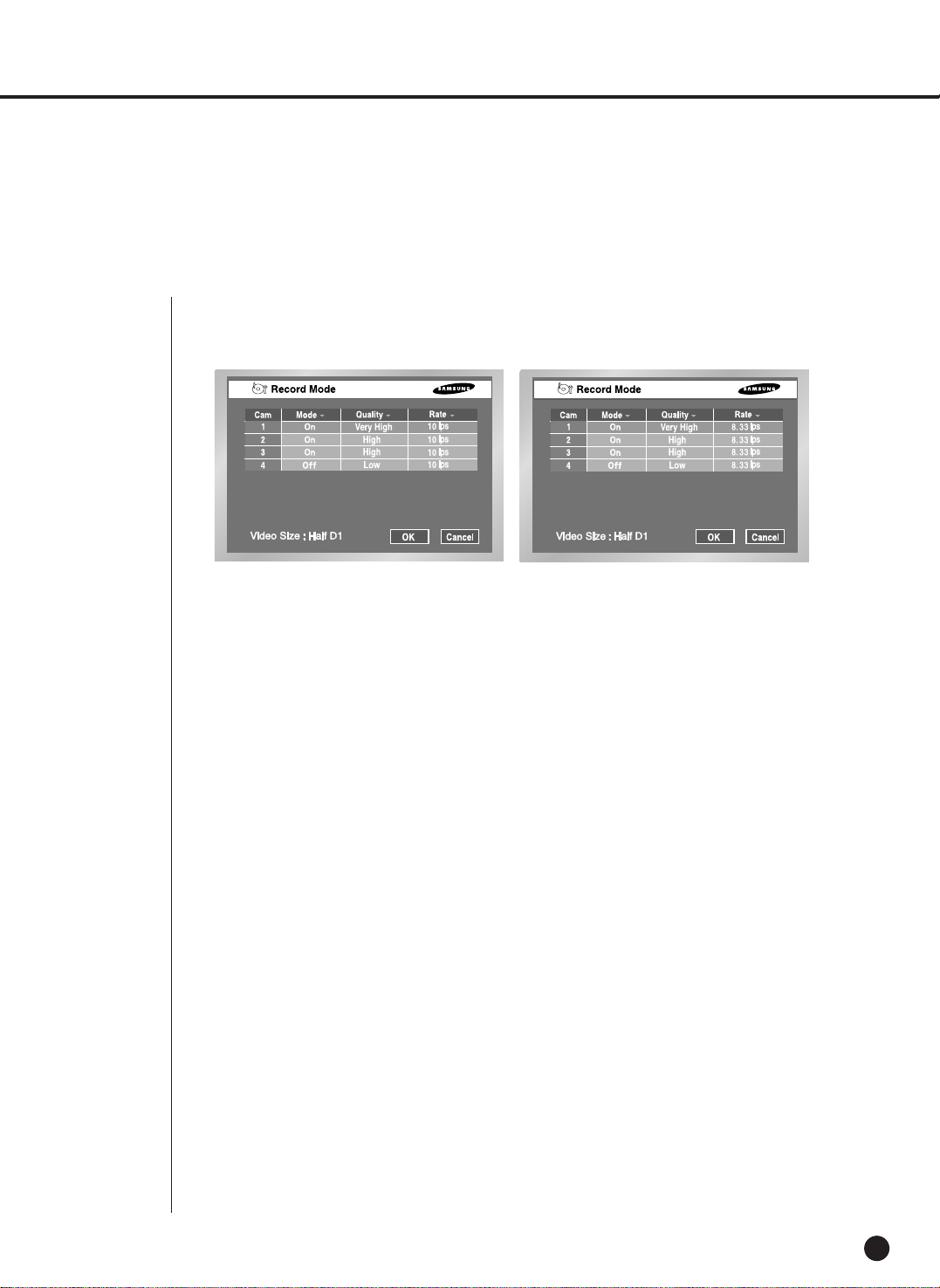
Record Mode
●
Details for Record Mode Menu are as follows.
If you press the front “REC” button, the mode value to be recorded will be set.
☛
For the setup of Event Recording Mode value, refer to 5-20. Event Recording
Mode Setup Menu.
● Mode
On : The current channel is recorded if the REC button is pressed.
Off : The current channel is not recorded even thought the REC button is pressed. The
default value is set to “On”.
● Quality
It sets the Quality.
Set to the one among Very high/High/Normal/Low.
● Rate
It sets the Rate means the number of screen recorded every second.
If it is set to 15 ips(NTSC)/12.5 ips(PAL), the system records too many screens per second
and the playback continues intermittently since recording is more detailed.
This is appropriate for concentrated monitoring zone setup.
IIn case of NTSC, select one out of 30 ips / 15 ips / 10 ips / 7.5 ips / 5 ips / 3 ips / 1 ips. In
case of PAL, select one out of 25 ips / 12.5 ips / 8.33 ips / 6.25 ips / 5 ips / 2.5 ips / 1 ips.
The Recording Menu will be activated depending on Video On/Off in the Camera Setup
(Menu5-12). When less than 2 cameras are activated at HALF D1, the frame rate of
recording may start from 30IPS and when more than 3 cameras are activated at Half D1,
the frame rate of recording may start from 15ips(NTSC) / 12.5ips(PAL). CIF supports from
30ips(NTSC) / 25ips(PAL) regardless of the number of activated camera.
● Video size
The Video size is displayed at the bottom of left.
NTSC
PAL

SHR-2040/2041/2042 USER’S MANUAL
5-19
● Video size
It sets the video to be recorded.
Half D1 : (NTSC) 720x240(N) ➝ Normal
(PAL) 720x288(N) ➝ Normal
CIF : (NTSC) 352x240(C) ➝ CIF
(PAL) 352x288(C) ➝ CIF
● Auto Deletion
Press the [Off] button at the bottom of left to select either OFF or On.
Select “On” to move to the Date selection button and to limit the search date.
If you select “Off”, you cannot move to the Date selection button and to limit the search
date.
The date is limited from 1 to 99 days.
Record Video size Mode
Note
Note
To select Full D1, set 1 CH Support to On in the monitoring mode.
5-20
5
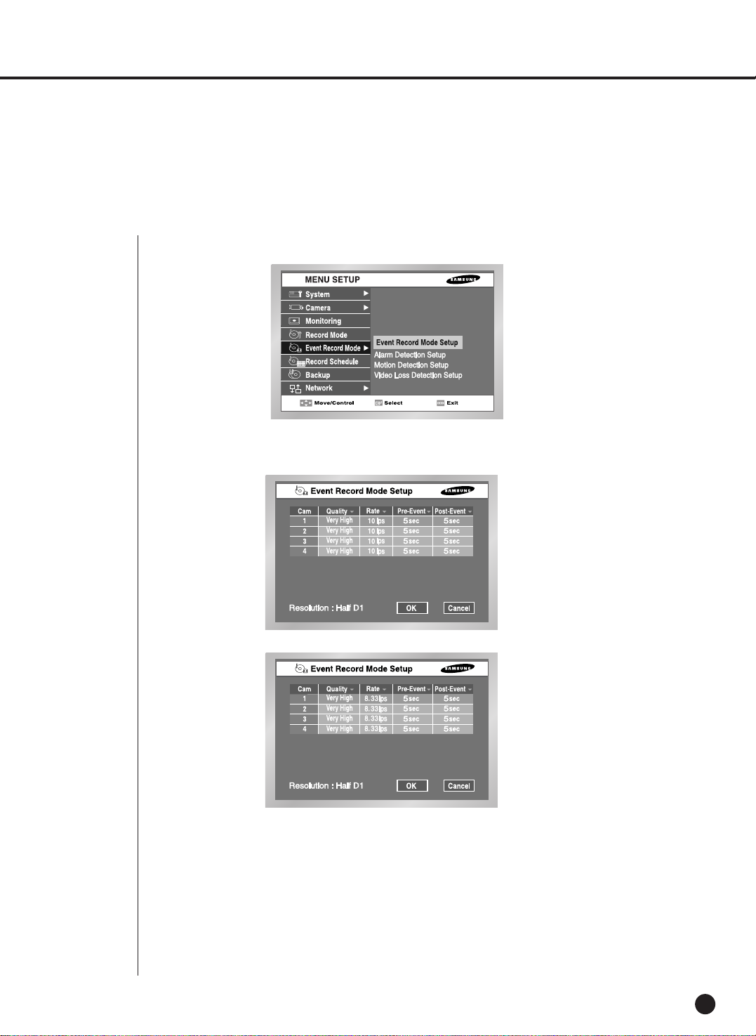
Event Record Mode
● The detailed items of Event Record Menu are as follows.
Event Record Mode setup
● Event Record Mode setup
Sets a mode to be recorded when an event occurs.
● V. Size (Video Size )
Sets the size of a screen to be recorded.
Half D1 : (NTSC) 720x240(N) ➝ Normal
(PAL) 720x288(N) ➝ Normal
CIF : (NTSC) 352x240(C) ➝ CIF
(PAL) 352x288(C) ➝ CIF
NTSC
PAL

SHR-2040/2041/2042 USER’S MANUAL
5-21
● Quality
Quality will be determined.
Select the one among Very High / High / Normal / Low.
● Rate
Sets the Rate the number of screen recorded every second.
It you set to 15ips, the system records too many screens per second and play continues
intermittently since recording is more detailed. This is appropriate for concentrated
monitoring zone setup.
In case of NTSC, select the one of 30 ips / 15 ips / 10 ips / 7.5 ips / 5 ips / 3 ips / 1 ips.
In case of PAL, select the one of 25 ips / 12.5 ips / 8.33 ips / 6.25 ips / 5 ips / 2.5 ips / 1 ips.
● The Event Recording setup menu will be activated depending on Video On/Off in
Camera Setup (Menu5-12).
● When the video size in the Camera Setup Menu is set to Half D1 and less than 2
cameras are activated, the frame rate of recording may start from
30ips(NTSC)/25ips(PAL) and when the video size in the recording mode is set to
Half D1 and more than 3 cameras are activated, the frame rate of recording may
start from 15ips(NTSC) / 12.5ips(PAL). CIF supports from 30ips(NTSC) /
25ips(PAL) regardless of the number of activated camera.
● Pre-Event
● Post-Event
Records the situation until Alarm is issued.
Off : No recording
5sec/ 10sec/ 20sec/ 30sec : The recording time options before Alarm issue
Records the situation since Alarm is issued.
Off : No recording
5sec/ 10sec/ 20sec/ 30sec/1min/3min/5min/10min/20min: Sets the recording time after an event occurs.
● Video size
The Video size is displayed at the bottom of left 5-19.
Pre-Event Section
Event time
Post-Event Section
Event time
5-22
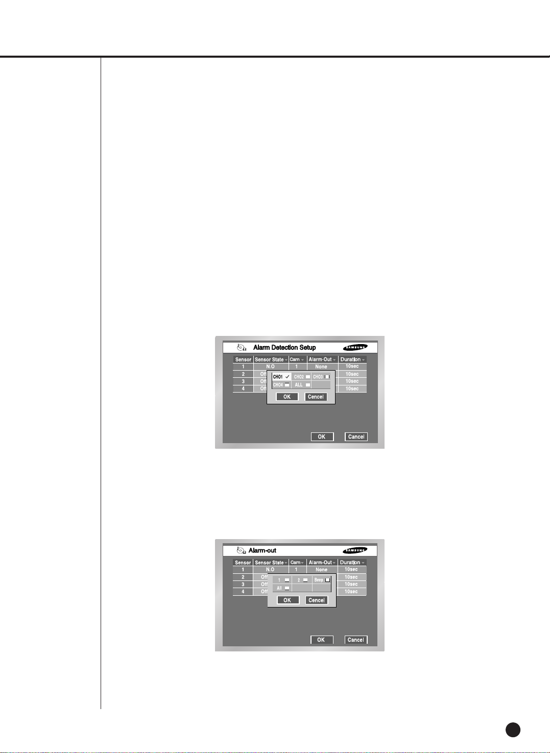
Alarm Detection Setup
● Off : Sensor does not operate.
① N.O(Normal Open) Sensor : Sensor remains open all the time and if closed,
an alarm will be issued. (A Contact)
➁ N.C(Normal Close) Sensor : Sensor remains closed all the time and if open,
an alarm will be issued. (B Contact)
● Cam
Sets a camera that will synchronize with the current sensor. The default value is currently
set to the sensor number. A sensor shall be synchronized with at least a camera.
Multi-selection is possible.
● Alarm-out
Sets the Alarm-Out when Alarm Sensor sounds.
5 Alarm Outs are supported un the present.
Choose an alarm-out that you want to synchronize with the current sensor.
Multi-selection is possible.
● Beep-Out
Sets the Alarm-Out Duration. Alarm-Out continues for the set value.
Off / 3sec / 5sec / 10sec / 20sec / 30sec
SHR-2040/2041/2042 USER’S MANUAL
5-23
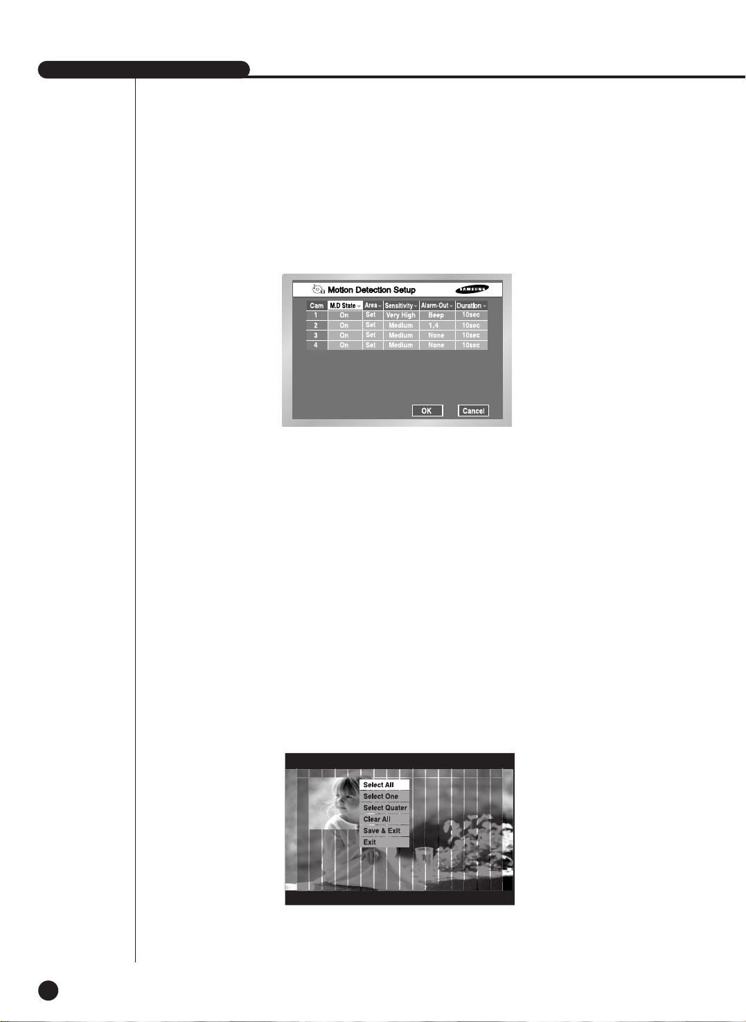
Motion Detection Setup
● Motion Detection Mode
Off : Motion Detection does not operate
On : Motion Detection operates.
● Area
Selects the Motion Detection area. It is composed of 45x40(NTSC)/45x48(PAL) sized Block.
It is impossible to set 4 block rows(Up/Down/Left/Right) to allow them to be displayed in all
monitors.
Select All : Selects the whole area.
Select Block : Selects a block every time. Selection is done by a toggle system.
Select Quarter : Splits the whole area into 4 pieces, which enables selecting a fourth of
the whole area.
Clear All : Cancels the whole area.
Save & Exit : Saves and exits.
Exit : Exits without saving.
5-24
● Sensitivity
Sets the sensitivity of motion detection. Sensitivity grade consists of Low ➝ Medium ➝ Very
High in the ascending order.
● Alarm-Out
Sets the Alarm-Out when Motion occurs.
5 Alarm Outs are supported.
Select an alarm-out that you want to synchronize with the current motion channel.
Multi-selection is possible.
● Beep-Out
Sets the Alarm-Out Duration. Alarm-Out continues for the determined duration.
Off/ 3sec/ 5sec/ 10sec/ 20sec/ 30sec
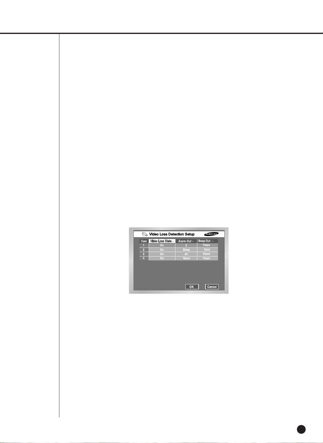
Video Loss Detection Setup
● Video Loss State
Off : Video Loss does not operate.
On : Video Loss operates.
● Alarm-Out
Selects the Alarm-Out when the current Video Loss occurs.
3 Alarm Outs are supported in the present. Select an alarm-out that you want to
synchronize with the current motion channel. Multi-selection is possible.
● Beep-Out
Sets Alarm-Out Duration. Alarm-Out continues for the determined duration.
Off/ 3sec/ 5sec/ 10sec/ 20sec/ 30sec
SHR-2040/2041/2042 USER’S MANUAL
5-25
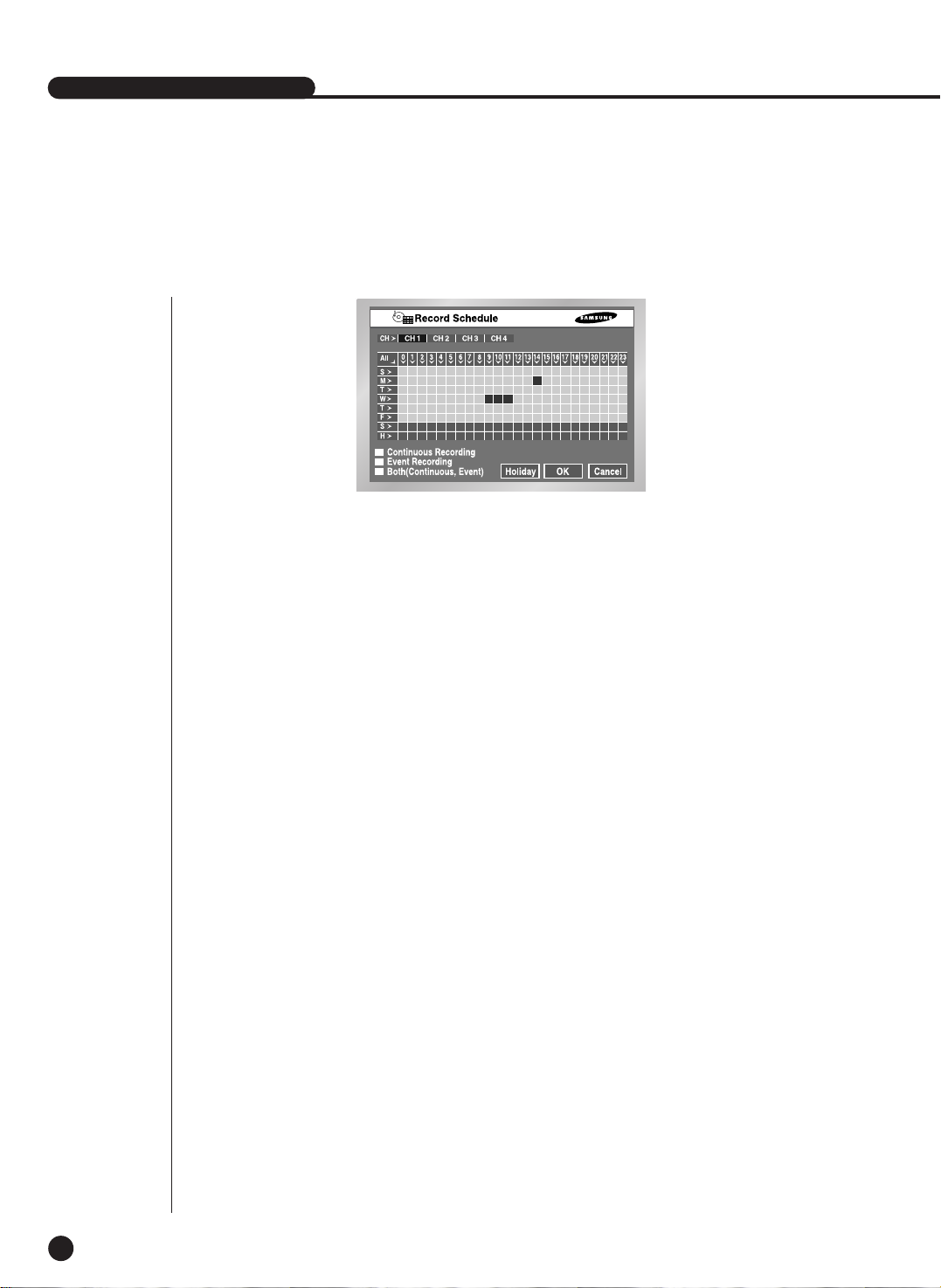
6
Record Schedule
This setup selects a time to record automatically.
Selection by the day or by the time is available.
The default value is set to “Event Record”.
● Press “CH >” copies the value of Channel 1 to all the channels.
● The horizontal axis numbered from 0 to 23 represents the time value.
The vertical axis numbered from S to H represents the day value. (H : Holiday)
Selection by the day or by the time is available.
● Pressing “ALL” converts the overall setting of the selection window into
Continuous ➝ Event Record ➝ Schedule/Event Record.
● Record Schedule
Recording starts automatically on the preset time.
Recording follows the condition that set in 5-18.Record Mode.
☛ Refer to 7-2 Record Schedule.
● Event Recording
Recording starts automatically when an event (Alarm/Motion Detection/Video Loss)
occurs within a setup time.
Recording follows the condition that set in 5-20.Event Record Mode setup.
☛ Refer to 7-3 Event Recording.
● Schedule Record is yellow, Event Record is Blue, and Schedule/Event
Record is red.
5-26
● Schedule / Event Record
On occurrence of Event, Continuous Recording is replaced with Event Recording Mode.
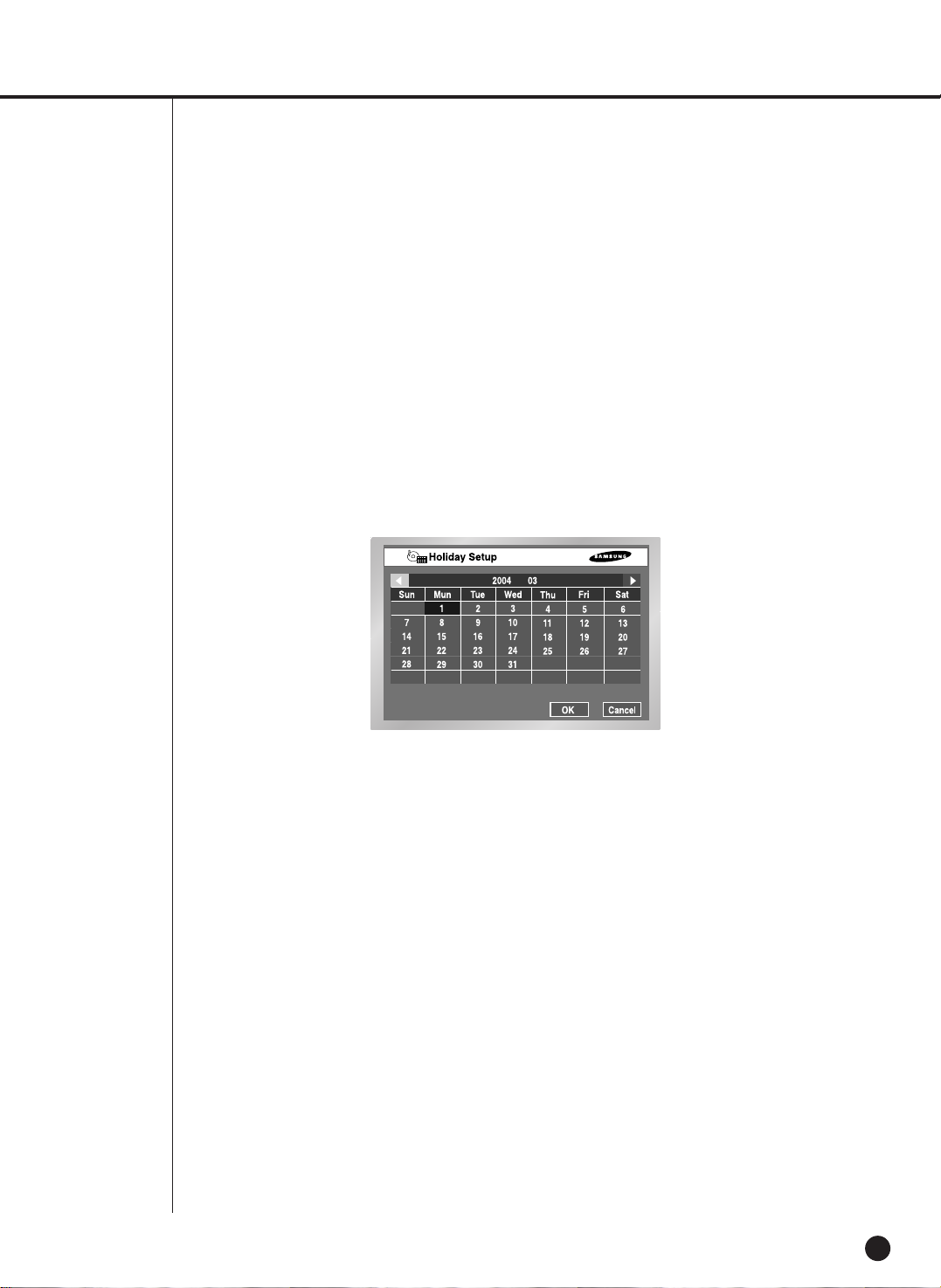
● Holiday
If you press “Holiday”, a calendar pops up and you are able to designate holidays.
Move to a date and press “Enter” to complete designation.
Press “Enter” once more to cancel designation.
“H” at the bottom of the table means a holiday.

SHR-2040/2041/2042 USER’S MANUAL
5-27
7
Backup
● If there is a device, the free space and the backup device is displayed.
● Select a date, time, and camera No. to backup, and press “Start”.
● When you change Start Date/Time or End Date/Time, free space keeps updated in
the Free Space zone.
● A file name is composed of Folder/File Name. A folder is composed of the backup
date(YYYYMMDD) while a file name is composed of the time(HHMM).
A file may be renamed by the virtual keyboard. A file name can composed of the
maximum 5 letters.
● In case that more than one backup device is connected, click the box in the
bottom of left corner to select a backup device.
● If there is no backup device, Warning sign pops up. Select and connect Backup
Device in 5-8.HDD Setup and proceed the backup.
● Press the “Stop” to stop the backup.
● Pressing Cancel during the Backup returns to the upper menu but this does not
affect the backup process.
● In case of USB HDD, the AVI check is impossible.
Caution
Caution
[In Backup Process]
Pressing THE “Cancel” returns to the upper menu but this does not affect Backup process.
Press “Stop” to stop the backup.
The speed of the set may down during the backup.
Note
Note
SHR-2042 supports the internal CD-R/W
Note
Note
In case of AVI backup, the backup playback is available in the PC, but it is not available in the set.
Note
Note
If you backup with USB CD/DVD or memory, be sure to use the less capacity than the real capacity of the
device. (some capacity is used for the purpose of the system).
Backup

5-28
8
Network
● Connection Mode
Designates the kind of the network connected to the main body of SHR-2040/2041/2042.
Static IP : When the main body is connected to the network with Static IP.
Dynamic IP : When the main body is connected to the network with Dynamic IP supplied
by DHCP.
ADSL(PPPoE) : When the main body is connected to the ADSL network with PPPoE.
● Bandwidth
Designates the network speed to which the main body of SHR-2040/2041/2042 is
connected.
Unlimited / 2 Mbps / 1 Mbps / 600 Kbps / 300 Kbps
In case of ADSL, the bandwidth should be selected 600 Kbps or 300 Kbps.
● Admin Password
Used for the connection between Smart Viewer and the set with the authority of Admin.
The password can be input 8 digits in maximum.
Press "Enter" and the left numeric keys from 1 to 4 for setup.
The default password for ADMIN is 4321.
● User Password
Used for the connection between Smart Viewer and the set with the authority of user.
The password can be input 8 digits in maximum.
Press "Enter" and the left numeric keys from 1 to 4 for setup.
The default password for USER is 4321.
Caution
Caution
When the main body is connected to the network using high speed LAN, set to 1 Mbps or 2
Mbps. When the main body is connected to the network supporting low bandwidth such as
ADSL, set below 600 Kbps. If you set Bandwidth high though the main body is connected to a
slow network, the network load will get heavy therefore the connection with Smart Viewer or
video monitoring may be instable.
Note
Note
In case of ADSL, the Protocol type is fixed to TCP.
IP Setup

SHR-2040/2041/2042 USER’S MANUAL
5-29
Caution
Caution
In case of ADSL, the audio is not played in the SmartViewer.
Caution
Caution
Be sure to set IP/Port/SubnetMask/Gateway/DNS to let Smart Viewer connect with the main
body of SHR-2040/2041/2042.
Wrong IP/Port/Gateway/SubnetMask/DNS may prevent Smart Viewer from being connected
to the main body of SHR-2040/2041/2042.
Please call the network manager or ADSL company to get each setting value.
● IP
Sets the IP address for the main body of SHR-2040/2041/2042 to connect with the network.
If the Connection Mode is set to Static IP, you shall type in IP yourself.
If the connection mode is Dynamic IP or ADSL(PPPoE), the IP allocated by the DHCP server or
ADSL company will be automatically displayed. In case of failure of DHCP or ADSLconnection,
000.000.000.000 will be displayed. Then, press OK to retry connection to get IP. If you continue to
fail in DHCP or ADSL connection, keep the main body of SHR-2040/2041/2042 off for a while and
turn it on for retry.
● Gateway
Sets the Gateway Address in the SHR-2040/2041/2042 main body.
● Subnet Mask
Sets the Subnet Mask Address in the SHR-2040/2041/2042 main body.
● DNS
Sets the DNS Address in the main body of SHR-2040/2041/2042. The default value of DNS is
168.126.63.1. Generally, you don°Øt have to alter the DNS default but you may be hard to
connect to the network sometimes if you use DHCP or ADSL.
In this case, call the network manager or ADSLcompany to set up a new DNS address.
● ADSL User ID
If the main body of SHR-2040/2041/2042 is connected with the ADSL(PPPoE) network, input
User ID subscribed to the ADSLcompany. You may input User ID with a Virtual keyboard as long
as 40 digits irrespective of alphabets, numbers, or symbols.
● Password
If the main body of SHR-2040/2041/2042 is connected to the ADSL(PPPoE) network, input the
user password subscribed to the ADSLcompany. You may input the password with a Virtual
keyboard as long as 40 digits irrespective of alphabets, numbers, or symbols.

5-30
Note
Note
If you want to connect IP Router with the main body of SHR-2040/2041/2042, you shall
designate a port for SHR-2040/2041/2042 in the IP Router setup menu.
The main body of SHR-2040/2041/2042 uses 4 ports for TCP communication.
In addition, if you want to use the DHCP function backed by IP Router to allocate Dynamic IP to
the main body of SHR-2040/2041/2042, you shall designate a port for the IP which
SHR-2040/2041/2042 has been allocated by the IP Router setup menu.
If you use IP Router, you are recommended to rather determine IP and Port numbers to be
allocated to the main body of SHR-2040/2041/2042 from the IP Router setup menu, set the
connection mode to Static IP for the main body of SHR-2040/2041/2042, and input the
determined IP and Port number in IP Router than use the DHCP function.
Please refer to the IP Router User’s Manual or call the manufacturer to set up IP Router.
Transfer Protocol Settings
● You may select either TCPor UDP for the protocol type.
If you select ADSLfrom the IP setup page, only TCP is available.
While TCP is selected, Audio transmission is not available.
● The available Port(TCP) ranges from 554 to 998 and the port number will be changed by 4.
Once the first digit is determined, the following 3 digits will change accordingly.
● The available Port(TCP) ranges from 8000 to 9760 and the port number will be changed by 160.
Once the first digit is determined, the remaining digits will change accordingly.
● Unicast is set to the default value and Multicast can be selected in Unicast / Multicast.
● Multicast IP will be activated and its setup is available only when Multicast is selected from
Multicast/Unicast.. Select a number from 224.0.0.0 to 239.255.255.255 for the D-Class IP
address.
● TTL will be also activated and the value from 0 to 255 can be set only when Multicast is selected
from Multicast / Unicast. The default value is 5.

SHR-2040/2041/2042 USER’S MANUAL
5-31
Callback Settings
● The Callback function is used to forward a callback message to the IP where SmartViewer
is in action in case Alarm, Motion Detection, or Video Loss event occurs.
● On/Off : Off is default but you may choose On.
● IPAddress : IP setting is available only when On is selected from On/off Setting.
Select the IP address of PC where SmartViewer is in action.
● Port(UDP) : You may choose one from 7900 to 7999 and the number changes by 1.
Selects the Port value for the Callback Connection menu from SmartViewer Setup.
● Retrial : You may choose one from 1 to 20 and the number changes by 1.
Caution
Caution
- Though Callback is set to ON, any Callback message will be created unless Alarm, Motion
Detection, and Video Loss are set by EventRecord.
- Unless the Callback button is clicked, SmartViewer does not receive any Callback message.

5-32
9
Network Setup
Port Setup for SmartViewer Connection
● The Port value for DVR registration of SmartViewer (Setup ➝ Site Setup) shall be as
same as that of the set (TCP).
● If you want to use the IP Router, you shall forward the activated Port depending on the
current setting value.
- If set to TCP, allocate 4 ports to the IP Router whose Port(TCP) was set.
- If set to UDP, allocate 4 ports whose Port(TCP) was set and 160 ports whose Port(UDP) was
set to the IP Router.
In the event of TCP Setup from Transfer Protocol Setup Page
● The ports allocated to Port(TCP) will be used for SmartViewer connection control and
stream forwarding.
In the event of UDP Setup from Transfer Protocol Setup Page
● The ports allocated to Port(TCP) will be used for SmartViewer connection control and
the ports allocated to Port(UDP) will be used for stream transfer.
● If you set to Multicast
- Both MultiCast IP and TTL Setup will be activated.
- MultiCast IP means the group address(D-Class IP Address : 224.0.0.0 ~ 239.255.255.255) for
MultiCast Forwarding.
- TTL(Time To Live) indicates how many Routers will be passed for MultiCast Forwarding.
- When you are unable to use Multicast by the Network(LAN or ADSL) characteristic as both Set
and SmartViewer are installed, the message, “Not Connected” will be displayed in the
SmartViewer screen. Please alter the TCP or UDP(Unicast) setting value.
● In the event of poor image from SmartViewer
- When the bandwidth of the network where Set is installed is smaller than the quantity of transfer
stream packet, the image is sometimes poor. Set the IPsetup bandwidth lower than the current
setting value. (In case of ADSL, it is recommended 300Kbps or 600Kbps for the bandwidth.)
- If this effort is no use, alter the protocol type to TCP.

Chapter 6
PTZ Camera Control
6

1
PTZ Camera Control Mode
6-1
● Select a proper PTZ camera Configuration value in MENU to enter PTZ Control Mode.
● Selected in MENU, the PTZ symbol( ) is displayed on the channel in the screen.
● If you press the Enter( ) button among direction keys in front of Split Screen, a blue
bar will appear in the monitor screen. Use direction keys to move this bar until you reach
the channel with the PTZ symbol and press the PTZ button in front of SHR-2040/2041/2042
to enter PTZ Camera Control Mode.
If you succeed in entering PTZ Camera Control Mode, the PTZ symbol on the monitor
screen will turn yellow from white while the PTZ button in front of SHR-2040/2041/2042 will
turn blue. PTZ Camera Control Mode supports Pan, Tilt, and Zoom operation.
SHR-2040/2041/2042 USER’S MANUAL
PTZ
¦
PTZ
TELE WIDE
VIEW
PRESET
6-2
● Other PTZ Camera Control Modes perform its control in a single screen. Press the channel
selection button in the left front to select the PTZ setting channel and press the PTZ button.
If you succeed in entering Single Screen PTZ Camera Control Mode, the PTZ symbol on
the screen will turn yellow from white while the PTZ button will turn blue. Single Screen PTZ
Camera Control Mode supports Pan, Tilt, and Zoom operation basically and Preset, Camera
Menu, and other functions additionally.
● Press the PTZ button in Live Mode to cancel PTZ Camera Control Mode. After cancellation,
the PTZ symbol on the screen will turn white from yellow while the PTZ button will lose its
blue light.
Note
Note
If you select Remote Control Device, you may not control PTZ Camera with
SHR-2040/2041/2042. It’s because the PTZ button in front of SHR-2040/2041/2042
remains inactivated.
Press the PTZ button and the PTZ ban icon( ) will appear. It’s because the RS-485 port
setup was done for Remote Control Device.
The some functions of PTZ camera are used under restriction.
Note
Note
When using the remote controller (SCC2000), direct camera control is available only for
Samsung Protocol in the remote controller (refer to the SCC2000 user manual). If there is no
PTZ control within the maximum 5 minutes in DVR, the PTZ mode is cancelled automatically.
It is for PTZ control in the remote viewer while not controlling PTZ.
[SHR-2040]
[SHR-2041]
[SHR-2042]
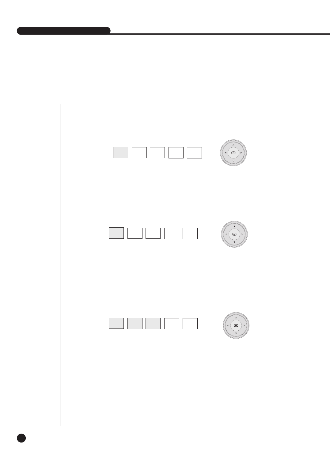
SHR-2040/2041/2042 USER’S MANUAL
2
Basic Operation of PAN, TILT, & ZOOM
6-3
● PAN
Press the LEFT or RIGHT button in front SHR-2040/2041/2042 in PTZ Camera Control
Mode to control PTZ Camera horizontally.
● TILT
Press the UP or DOWN button in front SHR-2040/2041/2042 in PTZ Camera Control Mode
to control PTZ Camera vertically.
PTZ
TELE WIDE
VIEW
PRESET
PTZ
TELE WIDE
VIEW
PRESET
● ZOOM
Press the TELE/WIDE button in front SHR-2040/2041/2042 in PTZ Camera Control Mode to
zoom in or out PTZ Camera.
PTZ
TELE WIDE
VIEW
PRESET
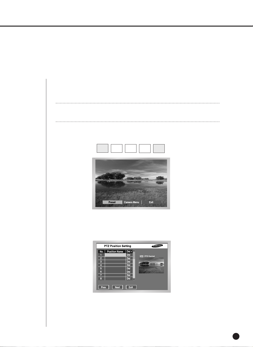
3
Preset Setup
6-4
● Records a certain position of PTZ Camera.
● Memorizes up to 20 PTZ Camera positions at the moment.
● Press the Preset button in front of SHR-2040/2041/2042 in Single Screen PTZ Camera
Control Mode to set up Preset.
● After Preset setup, press ENTER.
PTZ
TELE WIDE
VIEW
PRESET
Note
Note
For AD Protocol PTZ Camera, this memorizes only 7 Presets.
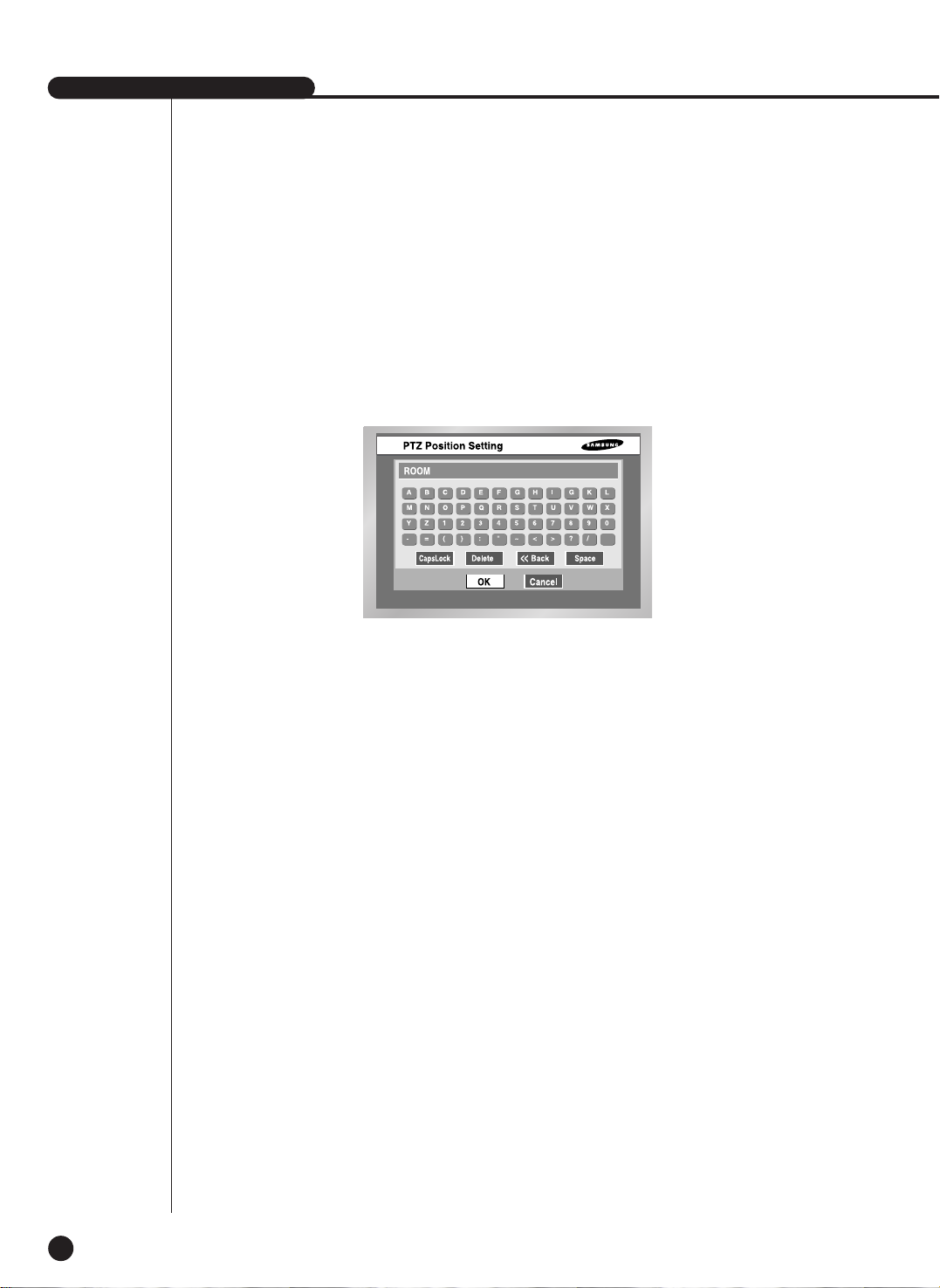
SHR-2040/2041/2042 USER’S MANUAL
6-5
● Move the cursor to right and press ENTER in PTZ Control Mode first. Then, press the
“Enter” to run P/T/Z/ operation mode in the PIP screen and press the “Enter” again to
cancel P/T/Z/ Motion Mode.
● Press Enter at the Position Name position to see Virtual Keyboard. Enter the type position
name and press the “OK” to save the position and position name.
● Press the “Del” to delete both Position and Position Name with the number.
● Click the Press Del ✓ on the top to delete all positions and position names in memory.
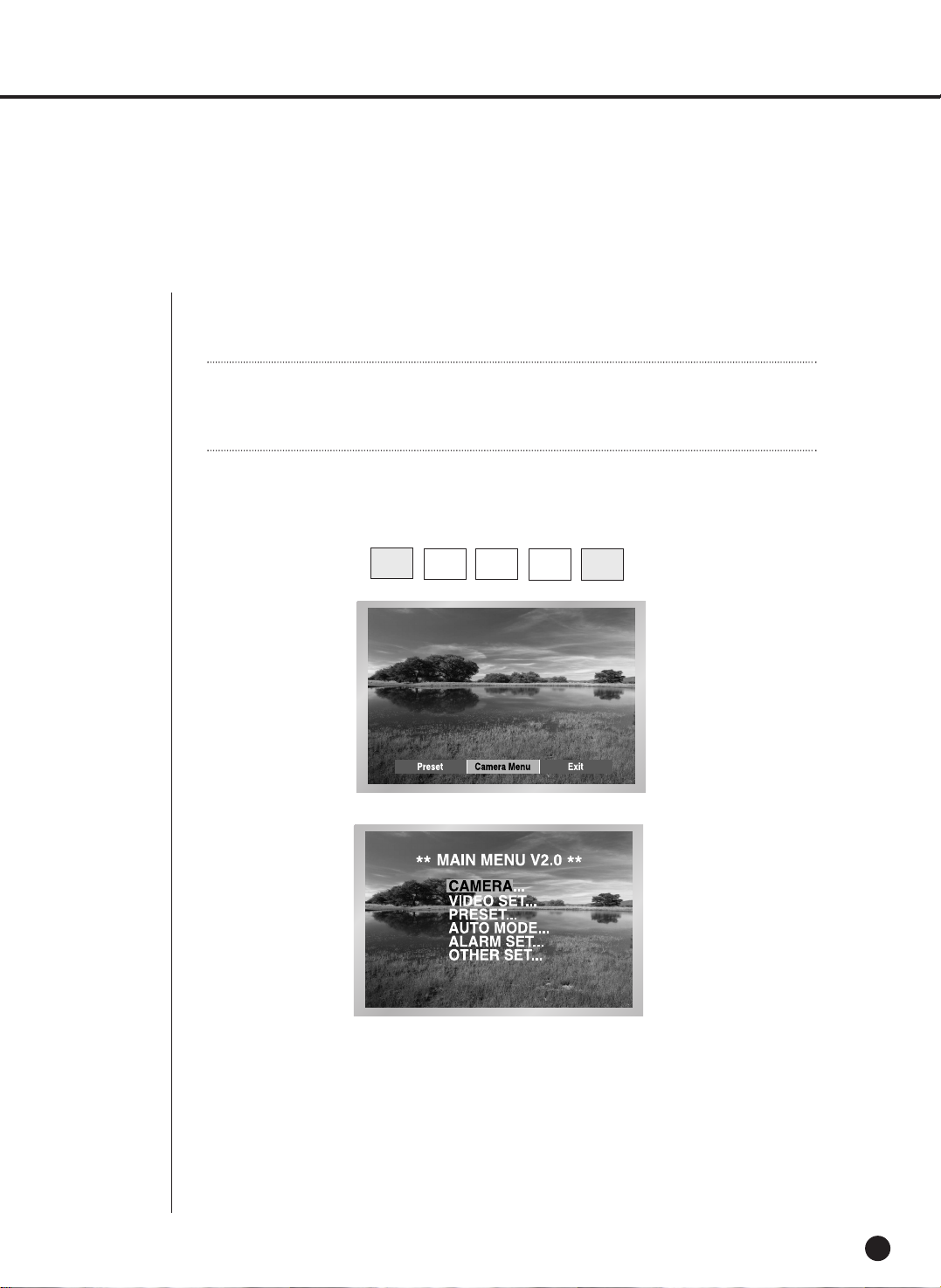
4
Camera Menu Setup
6-6
● Camera Menu is a menu supplied by PTZ Camera itself. This Menu sets up several
conditions of PTZ Camera.
● Press the Preset button in front of SHR-2040/2041/2042 in Single Screen PTZ Camera
Control Mode to select Camera Menu.
● Press the “Preset” button in front of SHR-2040/2041/2042 to return to the upper menu from
camera menu.
Note
Note
Pan. or Samsung Protocol Camera only is authorized for Camera Menu setup.
PTZ
TELE WIDE
VIEW
PRESET
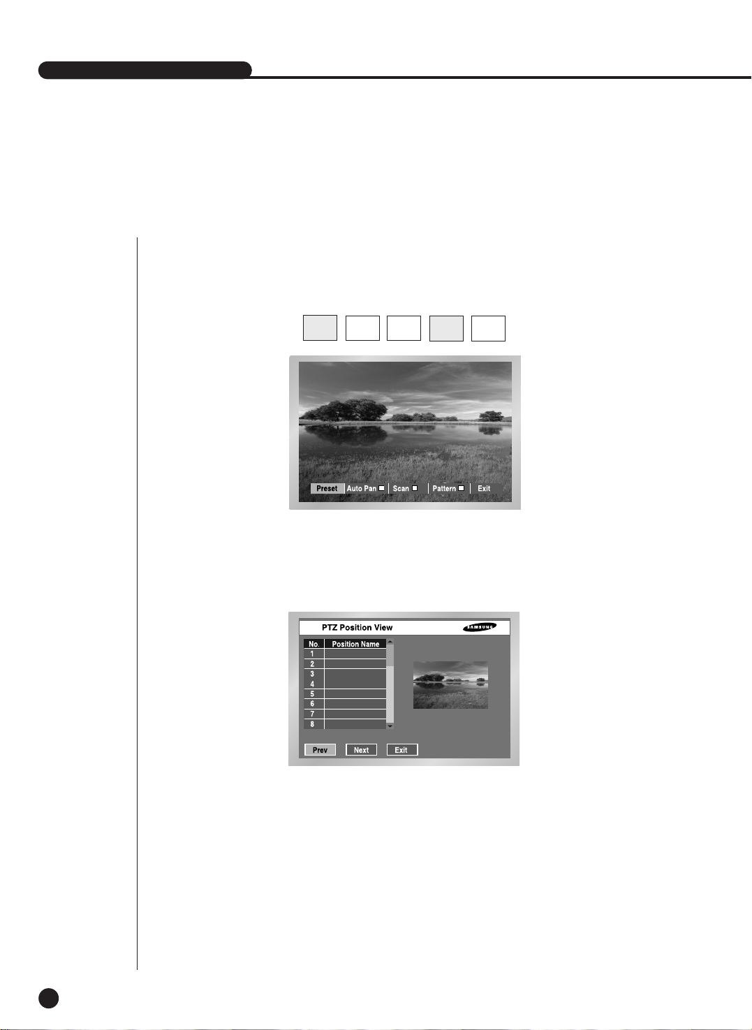
SHR-2040/2041/2042 USER’S MANUAL
5
Preset View
6-7
● Preset setup allows your movement to a certain saved position of PTZ Camera.
● Press the VIEW button in front of SHR-2040/2041/2042 in Single Screen
PTZ Camera Control Mode to select Preset.(For example, Samsung Protocol)
● Control the cursor until it reaches a preset position number that you want to move and you
can check it in the right PIP Screen.
PTZ
TELE WIDE
VIEW
PRESET
(For example, Samsung Protocol)
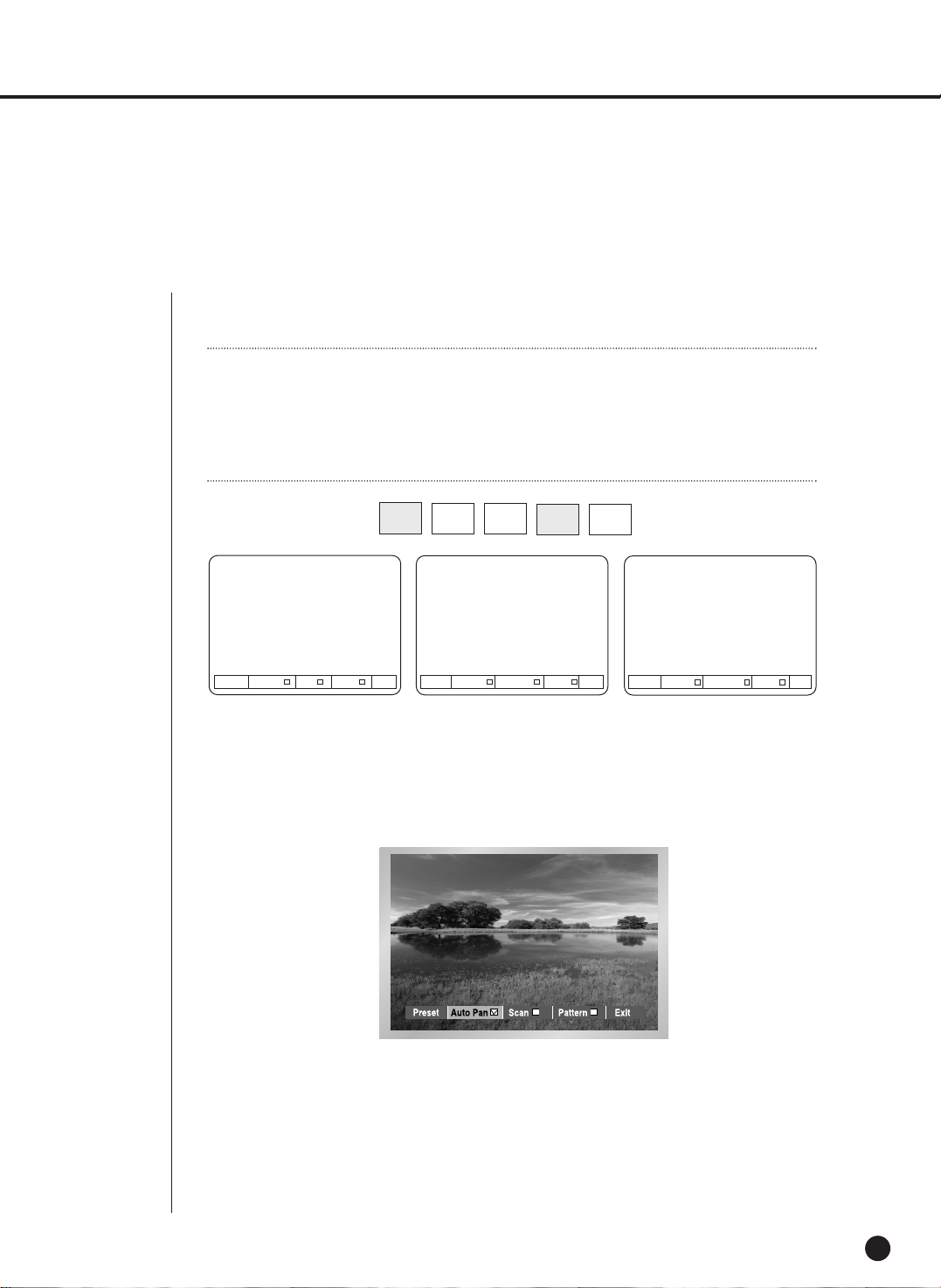
6
Other View
6-8
● Press the “VIEW” button in front of SHR-2040/2041/2042 in Single Screen PTZ Camera
Control Mode to supply PTZ Camera. This is a very special function.
● After you select a function, press Enter. Then the function will be checked and start running.
● If you select other function during the operation, the previous function will
be unchecked and the current function will be checked.
● If you put P/T/Z/ during the operation or enter the Preset Setup or Camera Menu Setup
during the operation, the function in action will be suspended and unchecked.
● Restarting SHR-2040/2041/2042 system during the operation has no effect.
The function continues its duty and remains checked.
PTZ
TELE WIDE
VIEW
PRESET
(For example, Samsung Protocol)
Preset Auto Pan Scan Pattern EXIT Preset Auto Pan Sequence Sort EXIT
Preset Auto Scan Frame Scan Pattern EXIT
Samsung
Pan. Pel.
Note
Note
Samsung, Pan., Pel-P, or Pel-D Protocol PTZ Camera supports this function.
Samsung : Auto Pan / Scan / Pattern
Pan. : Auto Pan / Sequence / Sort
Pel-(P,D) : Auto Scan / Frame Scan / Pattern

Chapter 7 Recording
7

1
REC (Normal Recording)
7-1
● Pressing REC the button starts recording as set in the record mode. Then, REC LED
lights on and a recording icon appears on the screen. During the recording in HDD,
the front HDD LED blinks.
● During the normal recording, you can stop it by pressing the REC button.
If the recording stops, REC LED lights out.
SHR-2040/2041/2042 USER’S MANUAL
WWarning
arning
If the work that has to stop the recording(Time change, File delete, HDD connect/disconnect
etc.) is performed during the recording, the current recording stops.

2
Schedule Recording
7-2
● While “Record Schedule” or “Schedule/Event recording” is selected in the Record Schedule
menu, Schedule Recording automatically starts. Otherwise, Schedule Recording remains
inactivated. During the Schedule Recording, Recording Icon appears on the screen.
During the recording in HDD, the front HDD LED blinks.
● If the Event Recording is selected, the recording starts at the every event.
In this case, the recording is saved according to the Event Record setup of the channel
(Video size, Recording quality, Frame rate, Pre-Alarm, Post-Alarm).
Note
Note
Even in case of an event, Event Recording will not start unless Event Recording or
Schedule/Event recording is selected in the Schedule Recording.
WWarning
arning
If the work that has to stop the recording(Time change, File delete, HDD connect/disconnect
etc.) is performed during the recording, the current recording stops.

SHR-2040/2041/2042 USER’S MANUAL
3
Event Recording
7-3
● Alarm Detection
Sensor operation mode in Alarm of Event Record menu shall be set to N.O (Normal Open)
or N.C (Normal Close).
● Motion Detection
Motion detection in the Event Recording menu shall be set to On.
● Video Loss Detection
Video Loss in Event Record menu shall be set to On.
● Event Recording Mode
Sets the recording type when an event occurs. In particular, depending on
PreAlarm Off or PostAlarm Off, PreAlarm or PostAlarm Recording is disabled
respectively.
WWarning
arning
If the work that has to stop the recording(Time change, File delete, HDD connect/disconnect
etc.) is performed during the recording, the current recording stops

Chapter 8
Search and Play
8

Before Use
8-1
● Pressing the “SEARCH” button shows Search Menu on the screen as seen above.
● Calendar Search searches a video file by the use of a calendar at the desired time.
● Event Search searches a video file recorded by the occurrence of event.
● Date/Time Search searches a video file by the entering of a day and time.
● “Go To First” searches a video file from the oldest one.
● “Go To Last” searches a video file from the latest one.
● Backup Search searches backed-up video file.
- Searches the backup video of backup device connected with the set.
SHR-2040/2041/2042 USER’S MANUAL

1
Calendar Search
8-2
● Be sure to select both the channel and the date to search. And press the [Start] button to
search for the desired time.
● Use a calendar to search the video file of desired time. Four channels in maximum are in
the range of search.
● Select the channel up to 4 by the use of ¦, and Enter button. And then the date column
will be displayed in thick blue when it has a video recorded in the channel.
● Use the ¦, button until you reach the Year/Month setup line and use both buttons and
the “Enter” button to select Year/Month.
● If you select a day by the [Enter] button, a checkbox will appear on the right of the date
number and the checkbox will be checked.
● Use the button until you reach the Time bar and move to the time you want with the
¦, button, and then press the Enter button to select a time.
● If you want to start the search, press the [Start] button. And press the [CANCEL] button to
move to the previous menu.
● You are able to search every 30 minutes.
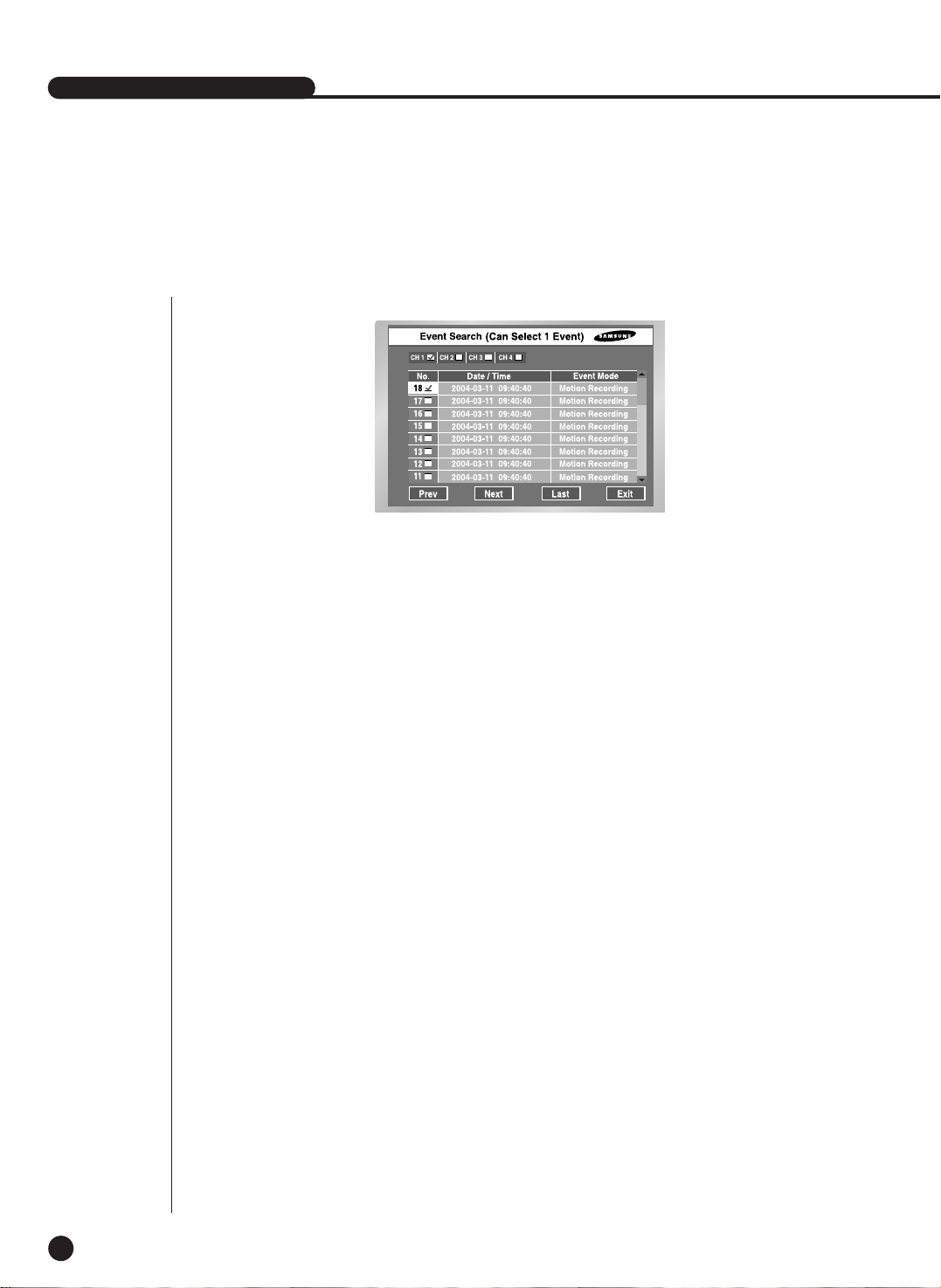
SHR-2040/2041/2042 USER’S MANUAL
8-3
● Searches Normal Recording, Schedule Recording, Alarm Recording, Motion Recording, and
V.Loss(Video Loss) Recording by the time.
● You shall select a channel to search to see the event information of the channel.
● On the basis of event information for each channel, the system searches a video file for the
event. Only one channel is allowed for video search.
● If you use both the [Enter] button and the ¦, button key to select a channel, the system
will show the list of event for the selected channel only.
● After channel selection, you can use the ¦, [Enter] button to select an event out of the
list. The checkbox on the left of the selected event number will be checked.
● If you want to start the search, use the button until you reach [START] and press the
[Enter] button. If you want to cancel the search, move to the [Exit] and press the [Enter]
button. If you wish to view the event list of the next screen, select [NEXT] and press the
[Enter] button and if you wish to view the event list of the previous screen, select [PREV]
and press the [Enter] button.
2
Event Search
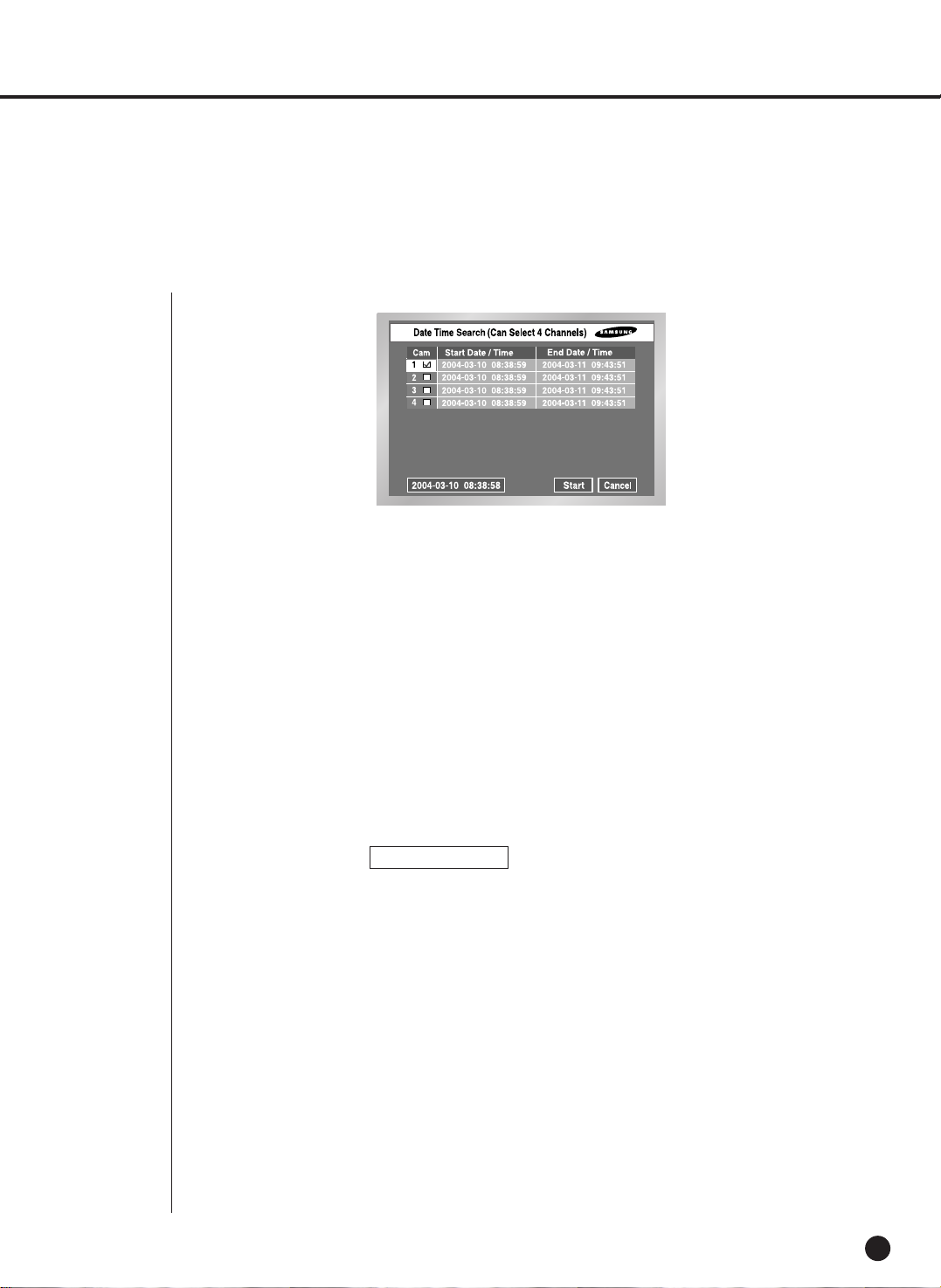
3
Date/Time Search
8-4
● Use the Day/Time information to search a video file at the time as you desire. Up to 4
channels can be searched at once.
● After you select a channel with the , , [Enter] button, the checkbox on the right of
selected event number will be checked.
● Use the button until you reach the Search Time setup line. Press the [Enter] button to
change the search time. Search Time change will be done by the
Year/Month/Day/Hour/Minute/ Second unit with the , , button. For your convenience,
you may hold on a key to change the value continuously.
● If you want to start the search, use the button until you reach [START] and press the
[Enter] button. If you want to cancel the search, move to the [CANCEL] and press the
[Enter] button.
● The time information, 2005-03-10 08:38:58 on the bottom left corner, represents the time
when play starts.
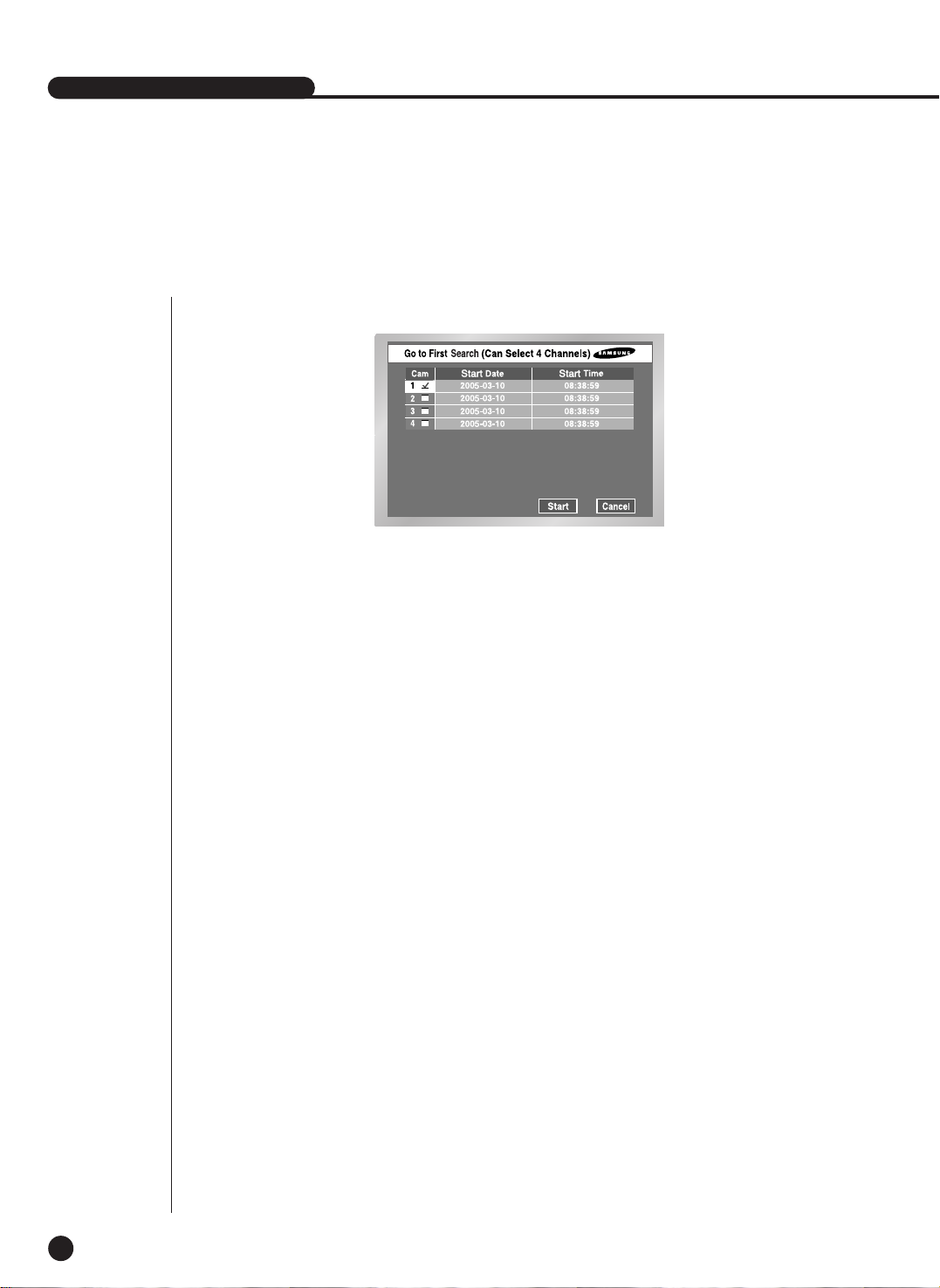
SHR-2040/2041/2042 USER’S MANUAL
8-5
● Searches the oldest one among recorded video files. Up to 4 channels can be searched at
once.
● After you select a channel with the , , [Enter] button, the checkbox on the right of the
selected channel number will be checked.
● Press the [Start] button want to start the search and to cancel. And press the [Cancel]
button to cancel the search.
4
Go to First Search
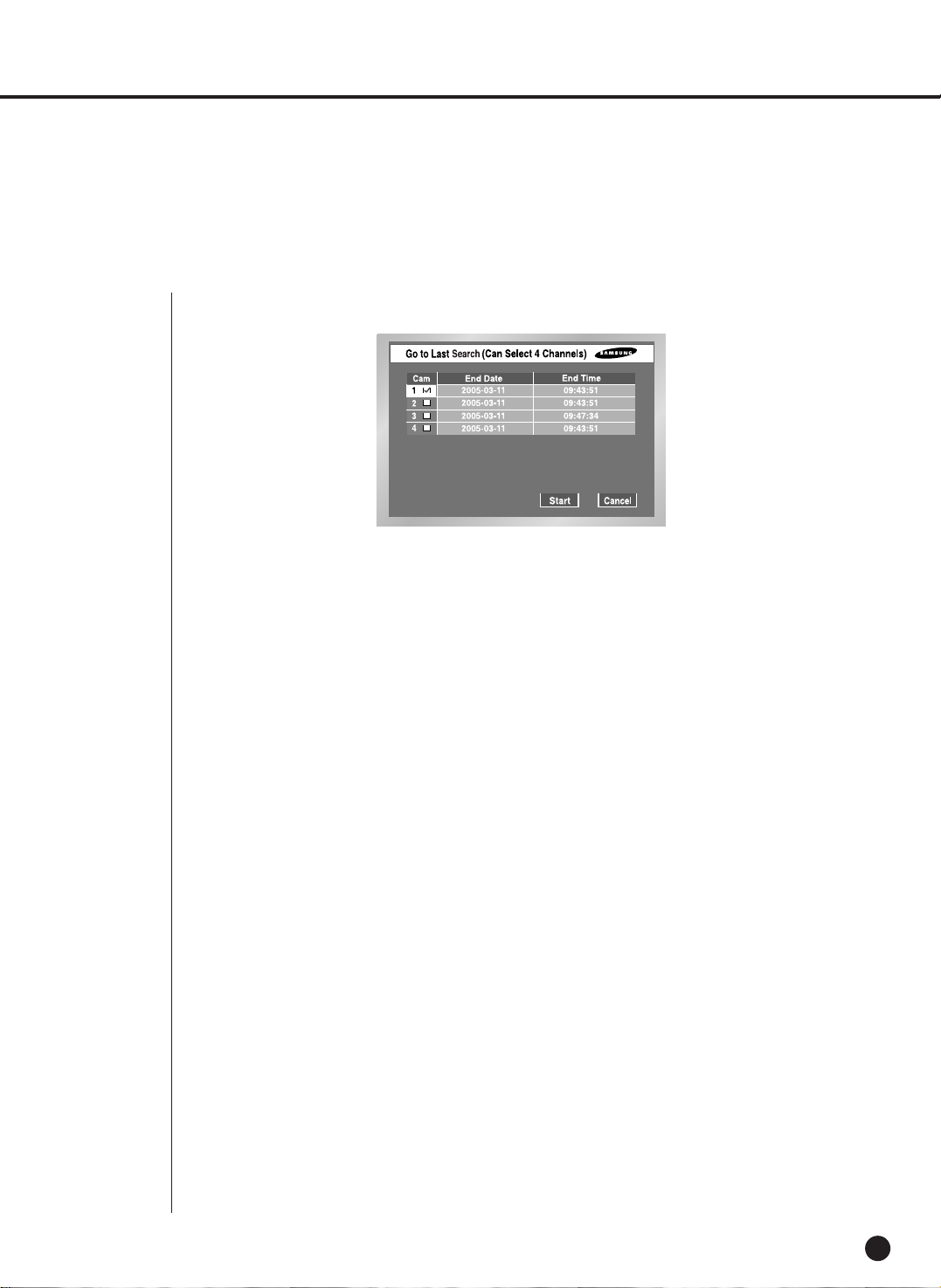
5
Go to Last Search
8-6
● Searches the latest one among recorded video files. Up to 4 channels can be searched at
once.
● After you select a channel with the , ,[Enter] button, the checkbox on the right of the
selected channel number will be checked.
● Press the [Start] button want to start the search and to cancel. And press the [Cancel]
button to cancel the search.
● If you start Go To Last Search during recording, the system will search the video image right
at the time of entering Search.

6
Backup
SHR-2040/2041/2042 USER’S MANUAL
8-7
● First, select the backup device.
● Mark the data of device.
● Select the file name to backup, and the detail information of a file is displayed in the below.
● The [Previous] button shows the previous page.
● The [Next] button shows the next page.
● The [Start] button plays the desired file.
● The [Exit] button exits the menu.
 Loading...