

Samsung SGH-X540 Schematics
GSM TELEPHONE
SGH-X540
GSM TELEPHONE
CONTENTS
1. Safety Precautions
2. Specification
3. Product Function
4. Array course control
5. Exploded View/Disassembly
and Assembly Instructions
6. MAIN Electrical Parts List
7. Block Diagrams
8. PCB Diagrams
9. Flow Chart of Troubleshooting
10. Reference data

CONTENTS
1. Safety Precautions
1-1. Repair Precaution......................................................................................................1-1
1-2. ESD(Electrostatically Sensitive Devices) Precaution...............................................1-2
2. Specification
2-1. GSM General Specification.......................................................................................2-1
2-2. GSM TX power Level...............................................................................................2-2
3. Product Function
4. Array course control
4-1. Software Adjustments................................................................................................4-1
4-2. Software Downloading...............................................................................................4-2
5. Exploded View and Parts list
5-1. Cellular phone Exploded View..................................................................................5-1
5-2. Cellular phone Part list.............................................................................................5-2
5-3. Disassembly & Assembly Instructions......................................................................5-4
6. MAIN Electrical Parts List
7. Block Diagrams
7-1. RF Solution Block Diagram......................................................................................7-1
7-2. Base Band Solution Block Diagram.........................................................................7-2
8. PCB Diagrams

CONTENTS
9. Flow Chart of Troubleshooting
9-1. Power On..................................................................................................................9-1
9-2. Initial ..........................................................................................................................9-3
9-3. Charging Part ...........................................................................................................9-5
9-4. SIM Part....................................................................................................................9-7
9-5. Microphone Part.........................................................................................................9-9
9-6. Speaker Part(Melody).............................................................................................9-11
9-7. Key Data Input.......................................................................................................9-13
9-8. Receiver Part..........................................................................................................9-14
9-9. Back Light(for Color Main LCD)............................................................................9-15
9-10. Key Back Light.....................................................................................................9-17
9-11. Camera Part..........................................................................................................9-18
9-12. GSM Receiver.......................................................................................................9-20
9-13. GSM Transmitter...................................................................................................9-21
9-14. DCS Receiver.......................................................................................................9-22
9-15. DCS Transmitter...................................................................................................9-23
9-16. PCS Receiver ......................................................................................................9-24
9-17. PCS Transmitter...................................................................................................9-25
10. Reference data

1. Safety Precautions
1-1. Repair Precaution
―
Repair in Shield Box, during detailed tuning. Take specially care of tuning or test, because
specipicty of cellular phone is sensitive for surrounding interference(RF noise).
―
Be careful to use a kind of magnetic object or tool, because performance of parts is damaged by
the influence of magnetic force.
―
Surely use a standard screwdriver when you disassemble this product, otherwise screw will be
worn away.
―
Use a thicken twisted wire when you measure level. A thicken twisted wire has low resistance,
therefore error of measurement is few.
―
Repair after separate Test Pack and Set because for short danger (for example an overcurrent
and furious flames of parts etc) when you repair board in condition of connecting Test Pack and
tuning on.
―
Take specially care of soldering, because Land of PCB is small and weak in heat.
―
Surely tune on/off while using AC power plug, because a repair of battery charger is dangerous
when tuning ON/OFF PBA and Connector after disassembling charger.
―
Don't use as you pleases after change other material than replacement registered on SEC System.
Otherwise engineer in charge isn't charged with problem that you don't keep this rules.
1-1
SAMSUNG Proprietary-Contents may change without notice
This Document can not be used without Samsung's authorization

afety Precautions
S
1-2. ESD(Electrostatically Sensitive Devices) Precaution
Several semiconductor may be damaged easily by static electricity. Such parts are called by ESD
(Electrostatically Sensitive Devices), for example IC,BGA chip etc. Read Precaution below.
You can prevent from ESD damage by static electricity.
―
Remove static electricity remained your body before you touch semiconductor or parts with
semiconductor. There are ways that you touch an earthed place or wear static electricity prevention
string on wrist.
―
Use earthed soldering steel when you connect or disconnect ESD.
―
Use soldering removing tool to break static electricity. , otherwise ESD will be damaged by static
electricity.
―
Don't unpack until you set up ESD on product. Because most of ESD are packed by box and
aluminum plate to have conductive power,they are prevented from static electricity.
―
You must maintain electric contact between ESD and place due to be set up until ESD is
connected completely to the proper place or a circuit board.
1-2
SAMSUNG Proprietary-Contents may change without notice
This Document can not be used without Samsung's authorization
2. Specification
2-1. GSM General Specification
GSM900
Phase 1
Freq.
Band[MHz]
Uplink/Downlink
ARFCN range 1~124
Tx/Rx spacing 45MHz 45MHz 95MHz 80MHz
Mod. Bit rate/
Bit Period
Time Slot
Period/Frame
Period
Modulation 0.3GMSK 0.3GMSK 0.3GMSK 0.3GMSK
890~915
935~960
270.833kbps
3.692us
576.9us
4.615ms
EGSM 900
Phase 2
880~915
925~960
0~124 &
975~1023
270.833kbps
3.692us
576.9us
4.615ms
DCS1800
Phase 1
1710~1785
1805~1880
512~885 512~810
270.833kbps
3.692us
576.9us
4.615ms
PCS1900
1850~1910
1930~1990
270.833kbps
3.692us
576.9us
4.615ms
MS Power 33dBm~5dBm 33dBm~5dBm 30dBm~0dBm 30dBm~0dBm
Power Class 5pcl ~ 19pcl 5pcl ~ 19pcl 0pcl ~ 15pcl 0pcl ~ 15pcl
Sensitivity -102dBm -102dBm -100dBm -100dBm
TDMA Mux 8 8 8 8
Cell Radius 35Km 35Km 2Km -
2-1
Speclflcation
2-2. GSM Tx Power Class
TX Power
control level
533±2dBm
631±2dBm
729±2dBm
827±2dBm
925±2dBm
10 23±2 dBm
11 21±2 dBm
GSM900
TX Power
DCS1800
control level
030±3dBm
128±3dBm
226±3dBm
324±3dBm
422±3dBm
520±3dBm
618±3dBm
716±3dBm
TX Power
control level
0 30±3 dBm
1 28±3 dBm
2 26±3 dBm
3 24±3 dBm
4 22±3 dBm
5 20±3 dBm
6 18±3 dBm
7 16±3 dBm
PCS1800
12 19±2 dBm
13 17±2 dBm
14 15±2 dBm
15 13±2 dBm
16 11±3 dBm
17 9±3dBm
18 7±3 dBm
19 5±3 dBm
814±3dBm
912±4dBm
10 10±4 dBm
11 8±4dBm
12 6±4 dBm
13 4±4 dBm
14 2±5 dBm
15 0±5 dBm
8 14±3 dBm
9 12±4 dBm
10 10±4 dBm
11 8±4dBm
12 6±4 dBm
13 4±4 dBm
14 2±5 dBm
15 0±5 dBm
2-2

3. Product Function
Main Function
―
SMS/EMS/MMS Message Service
―
WAP HTTP support
―
J2ME JAVA (MIDP 2.0/CLDC 1.1)
―
Speaker phone
―
16 Poly Melody
―
vCard, vCalendar
―
E-mail client
―
FM Radio
―
B/T Headset
3-1
SAMSUNG Proprietary-Contents may change without notice
This Document can not be used without Samsung's authorization

Product Function
3-2
SAMSUNG Proprietary-Contents may change without notice
This Document can not be used without Samsung's authorization
4. Array course control
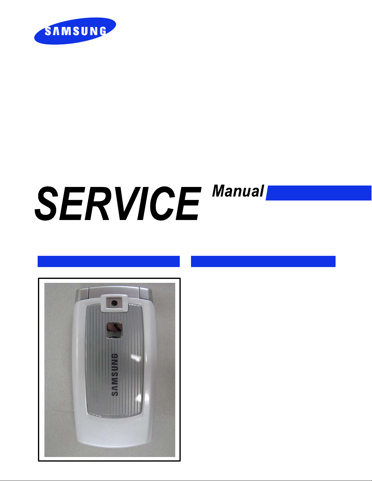
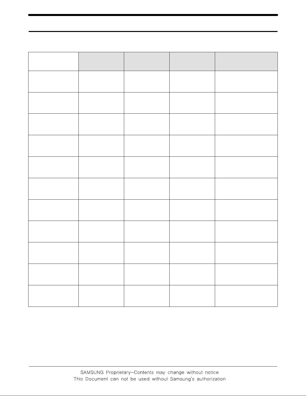
4-1. Software Adjustments
Serial Cable(CSA LL64151-A)
Power Cable
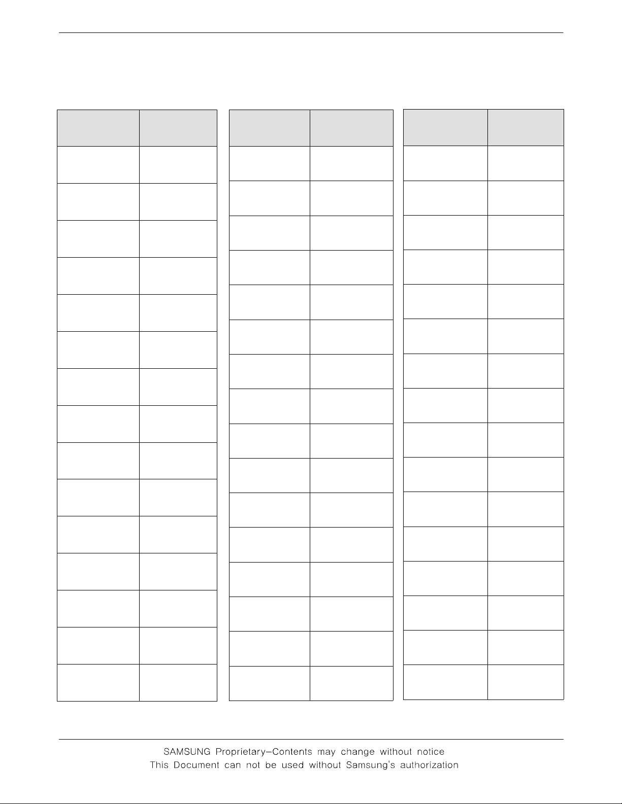
USB DATA CABLE (CSA LL11105 AWM)
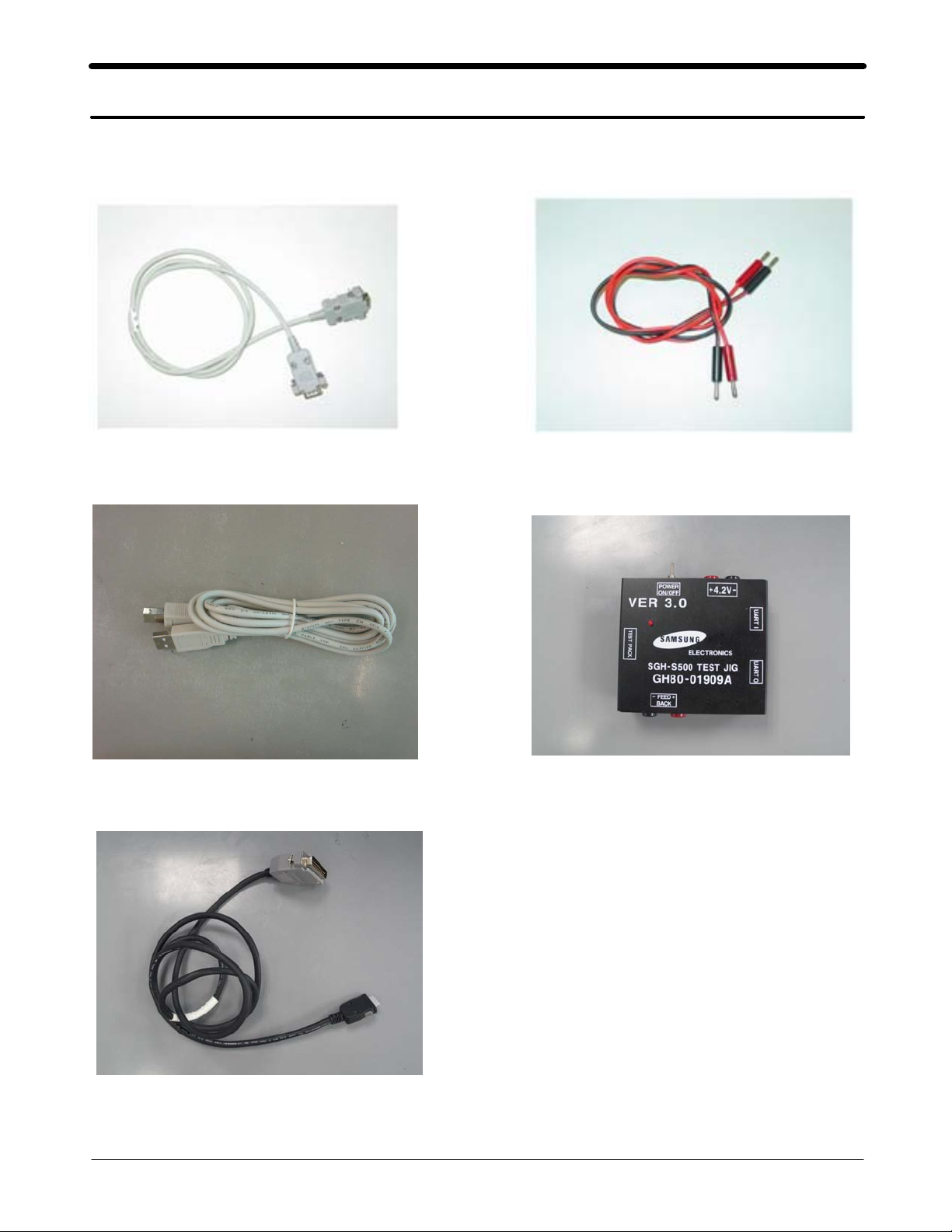
JIG CABLE (GH39-00217A)
JIG BOX (GH80-01909A)
4-1
SAMSUNG Proprietary-Contents may change without notice
This Document can not be used without Samsung's authorization
Array course control
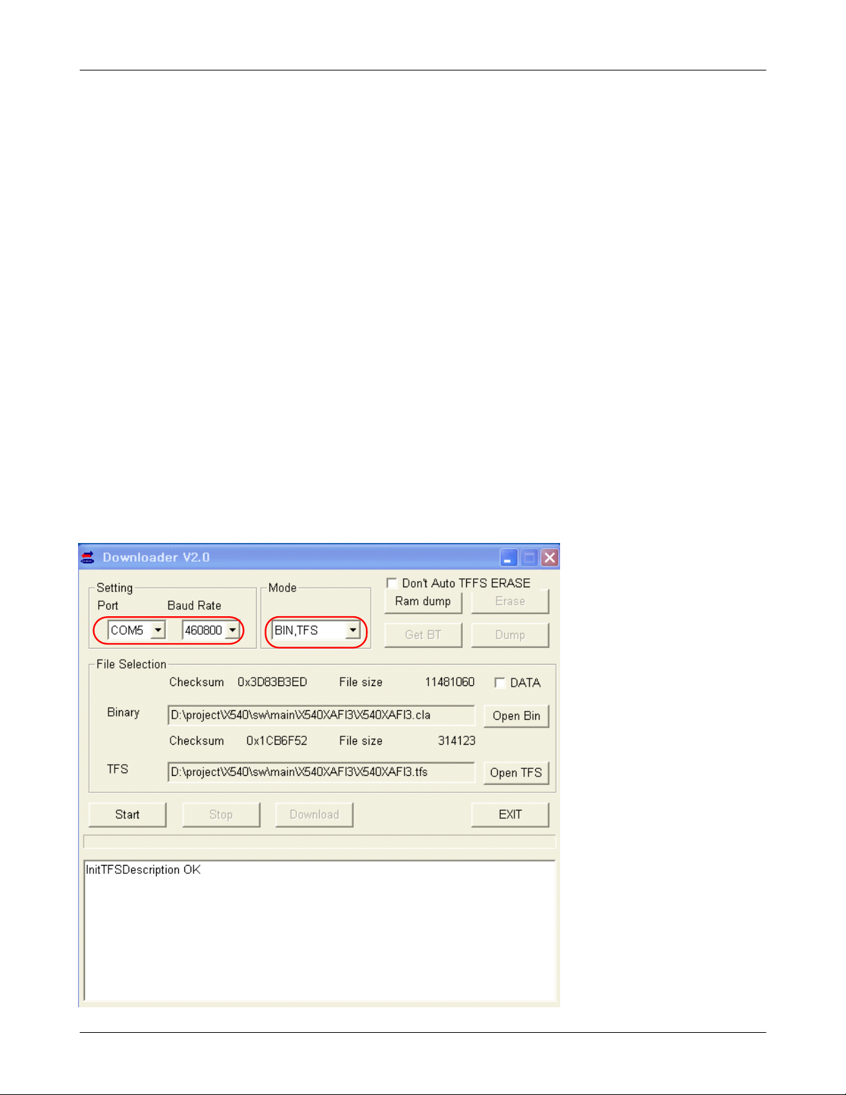
4-2. Software Downloading
4-2-1. Pre-requsite for Downloading
• Downloader Program(Klaus_Downloader_V2.0.exe)
• X540 Mobile Phone
• Data Cable
• Binary file, TFS file
4-2-2. S/W Downloader Program
■
Load the binary download program by executing the
“
Klaus_Downloader_V2.0.exe
. Select the connected serial port and the rate of speed
1
”
. Select the check box, the mode you want to download.
2
- if the binary file wanted, check only 'BIN'
- if the tfs file wanted, check only 'TFS'
- if all the files wanted, check 'BIN+TFS'
1
4-2
SAMSUNG Proprietary-Contents may change without notice
This Document can not be used without Samsung's authorization
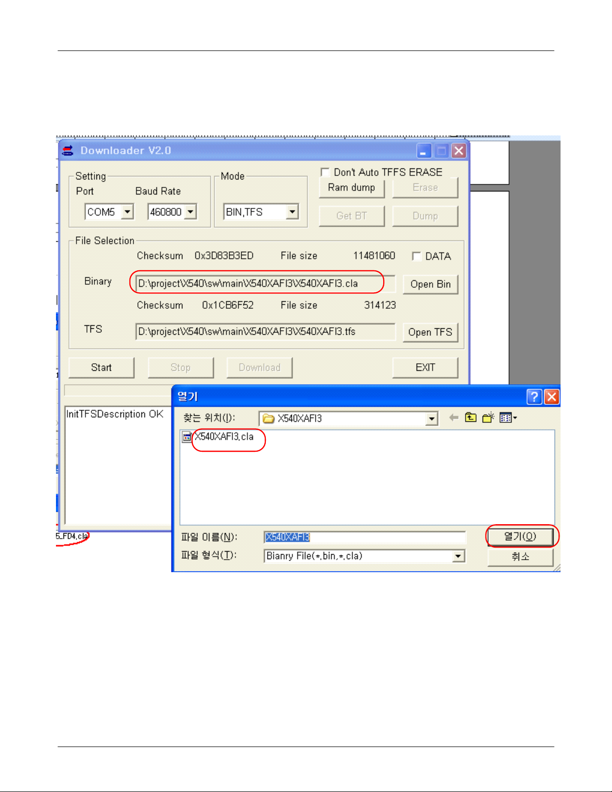
. Select the file(s) what you want to download
3
Array course control
4-3
SAMSUNG Proprietary-Contents may change without notice
This Document can not be used without Samsung's authorization

Array course control
4-4
SAMSUNG Proprietary-Contents may change without notice
This Document can not be used without Samsung's authorization
5. Exploded View/Disassembly&Assembly Instructions
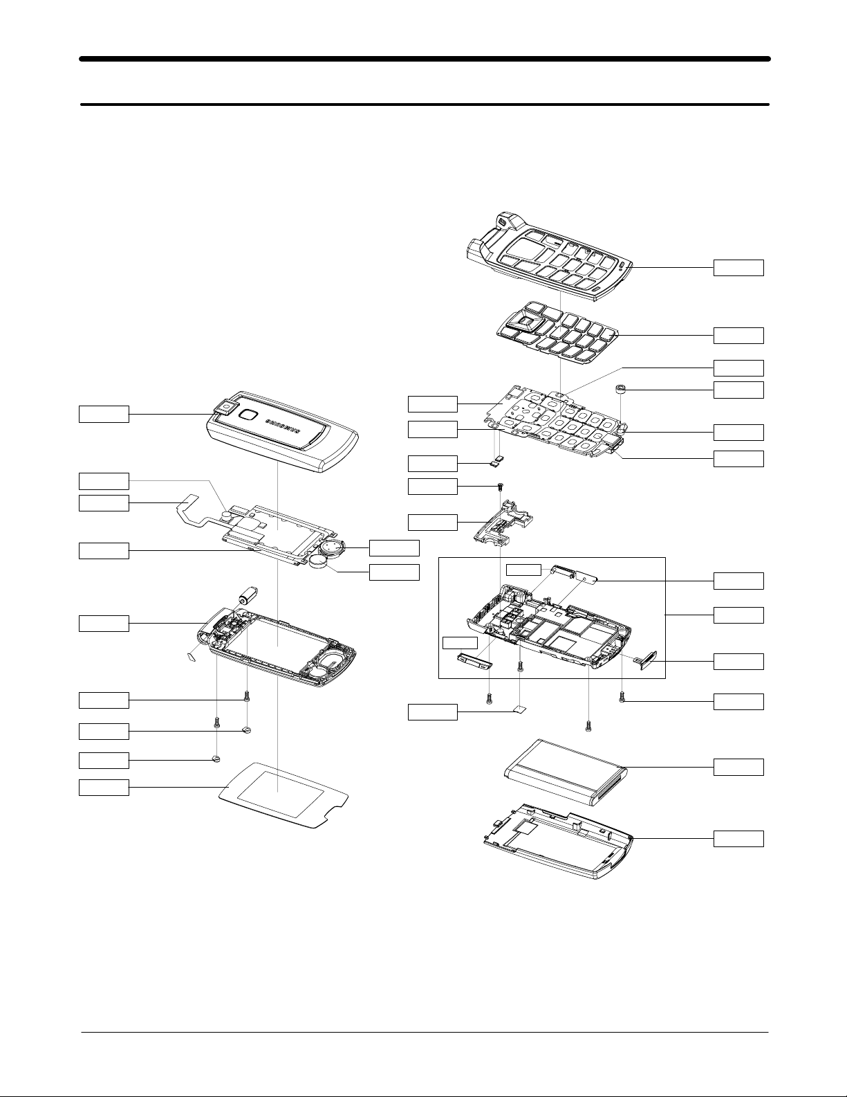
5-1. Cellular phone Exploded View
QFU01
QMP01
QVK01
QFR01
QKP01
QCA02
QMI03
QMI01
QCA01
QME03
QLC01
QFL01
QCR05
QSC07
QSC05
QMW01
QSP01
QMO01
QAN05
QCR12
QAN02
QRF01
QME01
QRF03
QCK01
QRE01
QVO01
QIF01
QCR05
QBA01
QBA00
5-1
SAMSUNG Proprietary-Contents may change without notice
This Document can not be used without Samsung's authorization
Exploded View/Disassembly&Assembly Instructions
5-2. Cellular phone Parts list
Design LOC Description SEC CODE
QAN02 INTENNA-SGHX540 GH42-01034A
QAN05 ASSY RUBBER-INTENNA GH98-02857A
QBA00 PMO-COVER BATT V2 GH72-35034A
QBA01 INNER BATTERY PACK-750MAH,BLK, GH43-02483A
QCA01 UNIT-SGHX540 CAMERA MODULE GH59-03655A
QCA02 UNIT-CAMERA KEY GH59-03643A
QCK01 PMO-CAMERA KEY V3 GH72-35488A
QCR05 SCREW-MACHINE 6001-001478
QCR05 SCREW-MACHINE 6001-001478
QCR12 SCREW-MACHINE 6001-001530
QFL01 ASSY CASE-FOLDER LOWER GH98-02385A
QFR01 ASSY CASE-FRONT GH98-02384A
QFU01 ASSY CASE-FOLDER UPPER GH98-02386A
QIF01 PMO-COVER IF GH72-34482A
QKP01 ASSY KEYPAD-(SER/GRY) GH98-03159A
QLC01 ELA ETC-SGHX540 LCD MODULE GH96-02269A
QME01 UNIT-METAL DOME GH59-03659A
QME03 PCB-CON TO CON GH41-01475A
QMI01 MICROPHONE-ASSY-SGHX540 GH30-00319A
QMI03 RMO-MIC HOLDER GH73-05342A
QMO01 MOTOR DC-SGHX540 GH31-00119B
QMP01 PBA MAIN-SGHX540 GH92-03230A
QMW01 ASSY COVER-MAIN LCD GH98-02388A
QRF01 MPR-TAPE GH74-26974A
QSC05 RMO-RUBBER SCREW CAP L GH73-08137A
QSC07 RMO-RUBBER SCREW CAP R GH73-08138A
QSP01 SPEAKER 3001-002072
QVK01 UNIT-VOLUME KEY GH59-03660A
QRE01 ASSY CASE-REAR GH98-02387A
QVO01 PMO-VOL KEY V3 GH72-35489A
QRF03 PMO-COVER EAR V3 GH72-35490A
5-2
SAMSUNG Proprietary-Contents may change without notice
This Document can not be used without Samsung's authorization
Exploded View/Disassembly&Assembly Instructions
Description SEC CODE
BAG PE 6902-000634
ADAPTOR-SGHD500 TA GH44-01451A
UNIT-EARPHONE(10P,SIL) GH59-03757B
LABEL(P)-WATER SOAK GH68-02026A
LABEL(P)-WATER SOAK GH68-02026A
MANUAL-SFC GH68-04336A
LABEL(P)-BARCODE RUSSIA GH68-08494A
MANUAL USERS-EU RUSSIAN GH68-12674A
LABEL(R)-MAIN(SER) GH68-12845A
BOX-UNIT(SER) GH69-04608A
CUSHION-CASE(EU) GH69-04932A
MPR-REMOVE TAPE LCD GH74-13804A
MPR-INSU TAPE GH74-15070A
MPR-BOHO VINYL LCD CONN GH74-15350A
MPR-TAPE LED GH74-17926A
MPR-INSU TAPE GH74-21312A
MPR-SPONGE LCD GH74-26952A
MPR-TAPE FPCB HOLE GH74-26973A
MPR-VINYL BOHO MAIN WINDOW GH74-26977A
MPR-INSU TAPE GH74-27176A
MPR-TAPE GH74-27509A
MPR-INSU TAPE GH74-27512A
MPR-INSU TAPE GH74-28085A
MPR-INSU TAPE GH74-28241A
MPR-TAPE GH74-28519A
MPR-INSU TAPE GH74-28609A
MPR-TAPE FPCB GH74-30174A
MPR-TAPE NAVI KEY GH74-30365A
MPR-TAPE ZTC BOARD GH74-30366A
MPR-TAPE LCD ELEC GH74-30367A
MPR-TAPE CAMERA CONN GH74-30368A
MPR-TAPE LOWER GH74-30369A
MPR-INSU TAPE YMU GH74-30370A
5-3
SAMSUNG Proprietary-Contents may change without notice
This Document can not be used without Samsung's authorization
Exploded View/Disassembly&Assembly Instructions
5-3. Disassembly and Assembly Instructions
― Disassembly
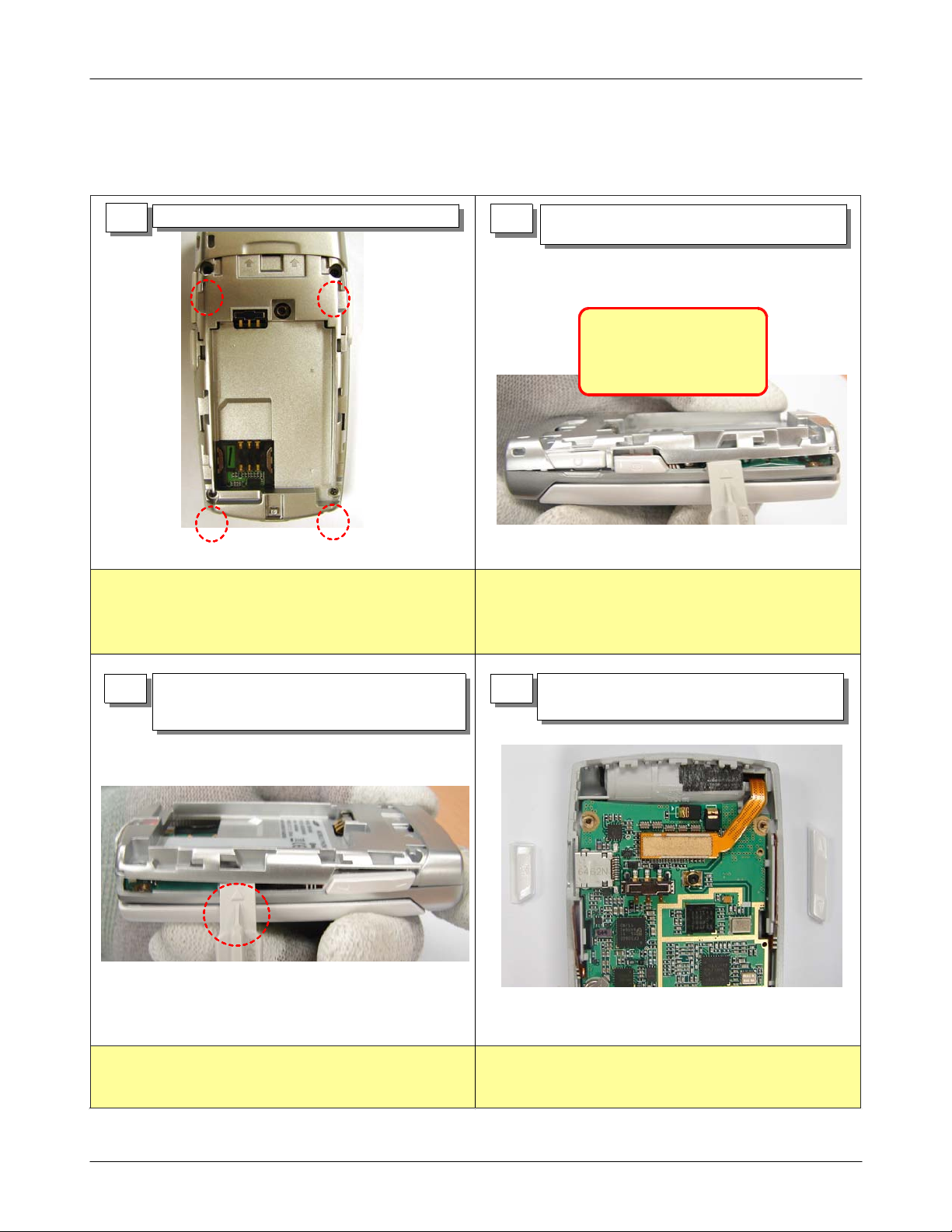
1) Release and remove the screws(4 point)
1
1)
Handle with care. No scratch.
1) Press the Rear Camera Hook side with
2
the dismantle tool to release the locker
-Please use dismantle tool
to open
-REAR case is too soft to be
broken
1)
Handle with care. No scratch
2)
Check no bending the board and front/rear cover.
1) Press the opposite side with the
3
dismantle tool to release the locker.
2) Open the rear cover.
1)
Handle with care. No scratch
2)
Check no bending the board and front/rear cover.
1) Realeae the camera key and the volume
4
key.
5-4
SAMSUNG Proprietary-Contents may change without notice
This Document can not be used without Samsung's authorization
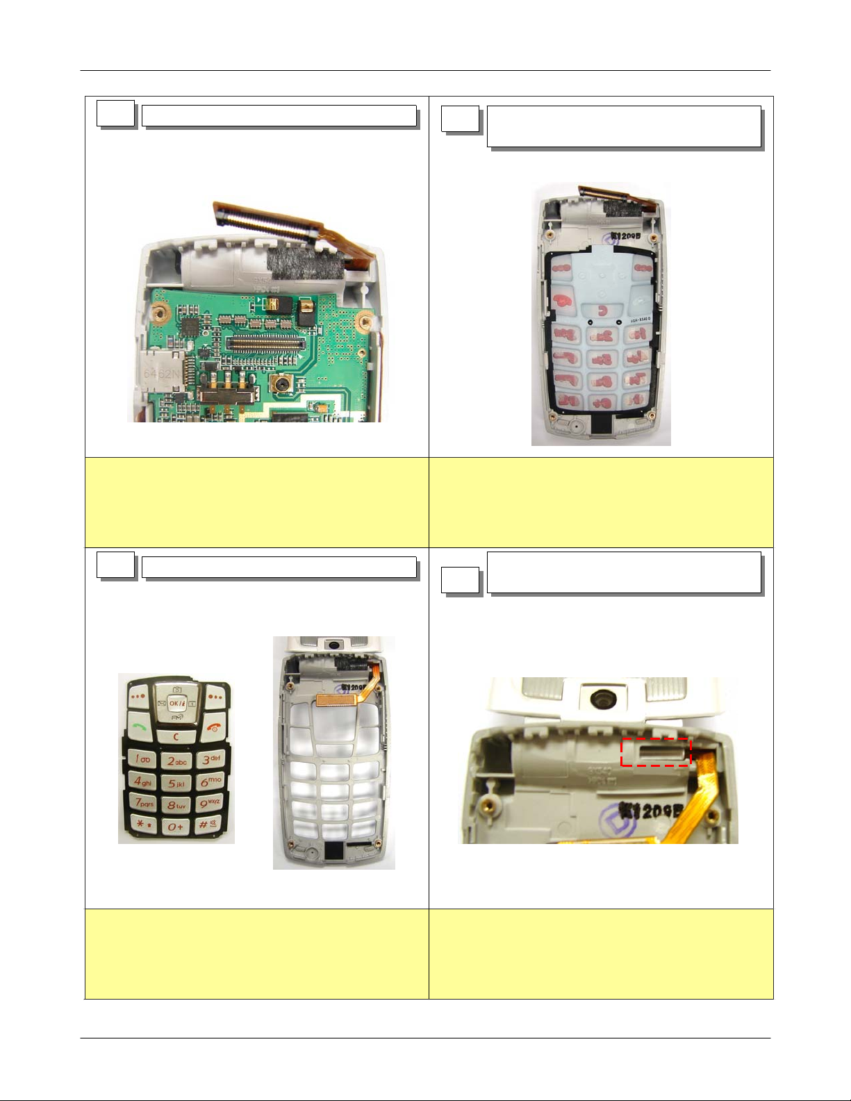
5
1) Release the LCD connector.
Exploded View/Disassembly&Assembly Instructions
1) After separate the CAMERA F-PCB and
6
VOLUME F-PCB, release the PBA.
1) Check the FPCB crack and connector damage.
7
1) Release the keypad in the FRONT.
1) Check the PBA's damage.
1)Remove the tape for preventing light
8
emission.
5-5
SAMSUNG Proprietary-Contents may change without notice
This Document can not be used without Samsung's authorization
Exploded View/Disassembly&Assembly Instructions
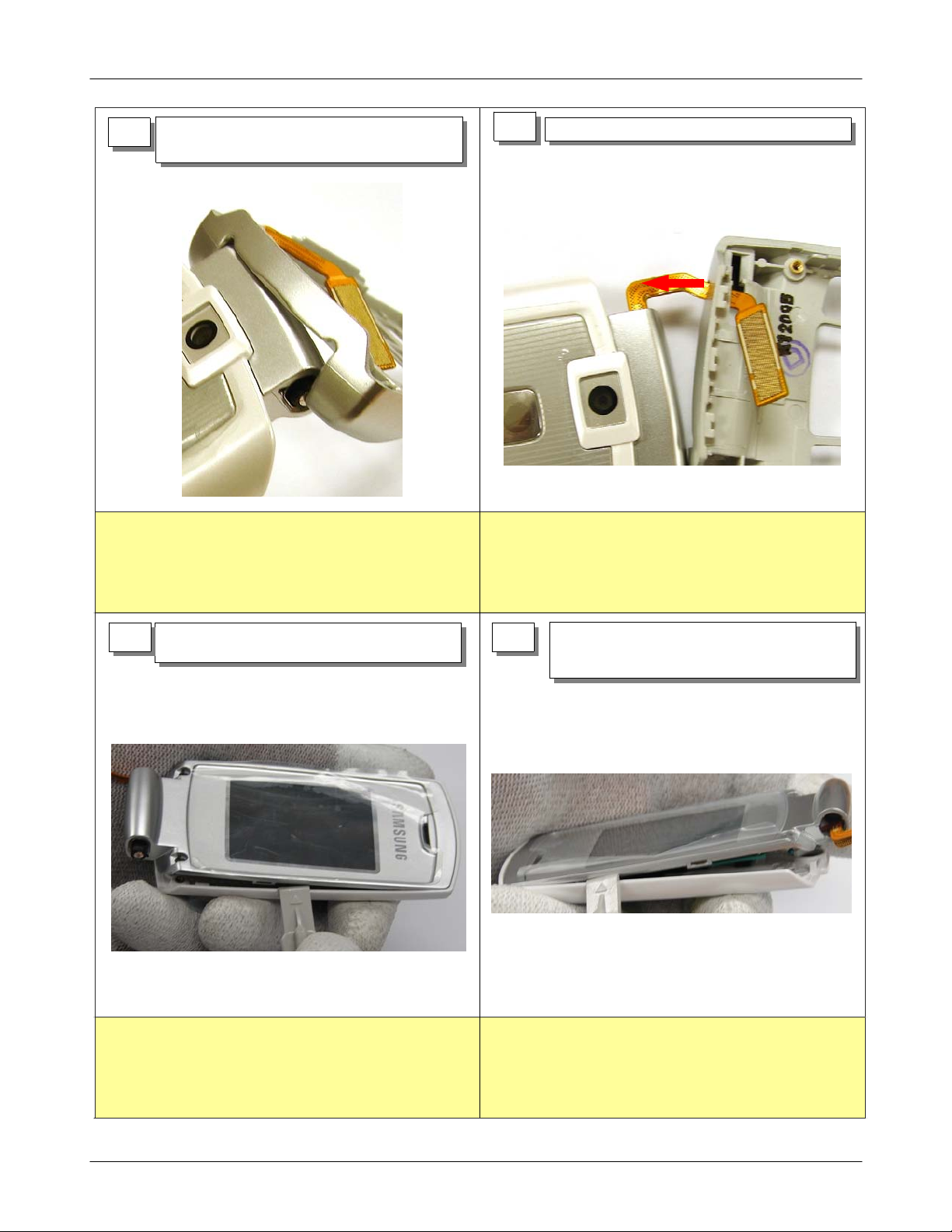
1)Press the hinge side with the dismantle
9
tool to release the locker.
1) Care with torn of F-PCB.
10
1) Release the F-PCB from the front side.
1) Care with F-PCB crack and CONNECTOR damage.
2)
Care with torn of F-PCB.
.
1) Press the side with the dismantle
11
tool to release the locker.
1)
Handle with care. No scratch
2)
Check no bending the board and front/rear cover
12
1)
.
2)
1) Press the opposite side with the
dismantle tool to release the locker.
2) Separate holding REAR.
Handle with care. No scratch
Check no bending the board and front/rear cover.
5-6
SAMSUNG Proprietary-Contents may change without notice
This Document can not be used without Samsung's authorization
Exploded View/Disassembly&Assembly Instructions
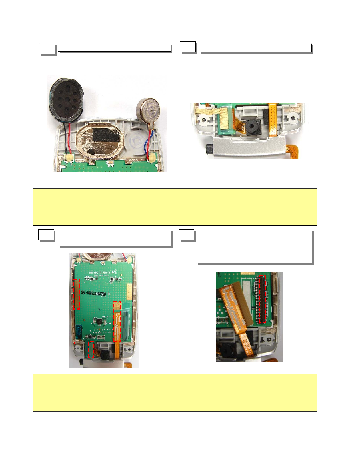
1) Remove SPEAKER and MOTOR from FOLDER.
13
1) Care with disconnecting of WIRE and soldering. 1) Care with torn of F-PCB.
14
1) Remove CAMERA MODULE from FOLDER.
1) Remove all shield tape on the LCD
15
MODULE.
1) Remove the insulate tape on the LCD
16
CONNECTOR.
2) Hold up LOCKER of LCD CONNECTOR,
separate LCD CONNECTOR.
1) Check correctly attaching Shielding tape. 1) Slowly separate for no damage to LCD.
5-7
SAMSUNG Proprietary-Contents may change without notice
This Document can not be used without Samsung's authorization

Exploded View/Disassembly&Assembly Instructions
1) Release the F-PCB HOLE SHEET.
17
2) Release LCD MODULE from FOLDER side.
3) Remove LCD CONNECTOR through HINGE.
1) Care with torn of F-PCB.
1) Remove all SHIELD TAPE on the PBA.
18
2) Remove insulation tape of CAMERA F-PCB
CONNECTOR side.
3) Hold LOCKER and separate CAMERA MODULE
1) Care with torn of F-PCB.
Slowly separate for no damage to CAMERA.
2)
5-8
SAMSUNG Proprietary-Contents may change without notice
This Document can not be used without Samsung's authorization
 Loading...