

Samsung SGH-i320 Service Manual
GSM TELEPHONE
SGH-i320
GSM TELEPHONE
CONTENTS
1. Safety Precautions
2. Specification
3. Product Function
4. Array course control
5. Exploded View and Parts list
6. Disassembly and Assembly
instructions
7. MAIN Electrical Parts List
8. Block Diagrams
9. PCB Diagrams
10. Flow Chart of Troubleshooting
11. Reference data

Contents
1. Safety Precautions
1-1. Repair Precaution ...........................................................................1-1
1-2. ESD(Electrostatically Sensitive Devices) Precaution ...........................1-2
2. Specification
2-1. GSM General Specification ..............................................................2-1
2-2. GSM TX power Level ......................................................................2-2
3. Product Function
4. Array course control
4-1. Downloading Binary Files .............................................................4-2
4-2. Pre-requsite for Downloading .......................................................4-2
4-3. S/W Downloader Program ............................................................4-3
5. Exploded View and Parts list
5-1. Cellular phone Exploded View ......................................................5-1
5-2. Cellular phone Parts list ...............................................................5-6
6. Disassembly and Assembly instructions
6-1. Disassembly .............................................................................6-1
6-2. Assembly .................................................................................6-4
7. MAIN Electrical Pa rts List
8. Block Diagrams
9. PCB Diagrams

Contents
10. Flow Chart of Troubleshooting
10-1. Baseband .............................................................................10-1
10-1-1. Power ON .......................................................................10-1
10-1-2. Initial .............................................................................10-4
10-1-3. SIM Part ........................................................................10-6
10-1-4. Microphone Part ..............................................................10-7
10-1-5. Speaker Part_1(MP3, SPEAKER PHONE) ............................10-8
10-1-6. Speaker Part_2(RECEIVER) .............................................10-10
10-1-7. Charging Part ................................................................10-11
10-2. RF .....................................................................................10-13
10-2-1. EGSM RX ......................................................................10-13
10-2-2. DCS RX ........................................................................10-15
10-2-3. PCS RX ........................................................................10-16
10-2-4. EGSM TX ......................................................................10-17
10-2-5. DCS TX ........................................................................10-18
10-2-6. PCS TX ........................................................................10-19
11. Reference data

1. Safety Precautions
1-1. Repair Precaution
●
Repair in Shield Box, during detailed tuning.
Take specially care of tuning or test,
because specipicty of cellular phone is sensitive for surrounding interference(RF noise).
●
Be careful to use a kind of magnetic object or tool,
because performance of parts is damaged by the influence of manetic force.
●
Surely use a standard screwdriver when you disassemble this product,
otherwise screw will be worn away.
●
Use a thicken twisted wire when you measure level.
A thicken twisted wire has low resistance, therefore error of measurement is few.
●
Repair after separate Test Pack and Set because for short danger (for example an
overcurrent and furious flames of parts etc) when you repair board in condition of
connecting Test Pack and tuning on.
●
Take specially care of soldering, because Land of PCB is small and weak in heat.
●
Surely tune on/off while using AC power plug, because a repair of battery charger is
dangerous when tuning ON/OFF PBA and Connector after disassembing charger.
●
Don't use as you pleases after change other material than replacement registered on SEC
System.
Otherwise engineer in charge isn't charged with problem that you don't keep this rules.
1-1
SAMSUNG Proprietary-Contents may change without notice
This Document can not be used without Samsung's authorization

Safety Precautions
1-2. ESD(Electrostatically Sensitive Devices) Precaution
Several semiconductor may be damaged easilly by static electricity. Such parts are called by
ESD(Electrostatically Sensitive Devices), for example IC,BGA chip etc. Read Precaution below.
You can prevent from ESD damage by static electricity.
●
Remove static electricity remained your body before you touch semiconductor or parts with
semiconductor. There are ways that you touch an earthed place or wear static electricity
prevention string on wrist.
●
Use earthed soldering steel when you connect or disconnect ESD.
●
Use soldering removing tool to break static electricity. , otherwise ESD will be damaged by
static electricity.
●
Don't unpack until you set up ESD on product. Because most of ESD are packed by box
and aluminum plate to have conductive power,they are prevented from static electricity.
●
You must maintain electric contact between ESD and place due to be set up until ESD is
connected completely to the proper place or a circuit board.
1-2
SAMSUNG Proprietary-Contents may change without notice
This Document can not be used without Samsung's authorization
2. Specification
2-1. GSM/WCDMA General Specification
EGSM 900
Phase 2
Freq.
Band[MHz]
Uplink/Downlink
ARFCN range 0~124 & 975~1023 512~885 512~810
Tx/Rx spacing 45 MHz 95 MHz 80 MHz
Mod. Bit rate/
Bit Period
Time Slot
Period/Frame
Period
Modulation 0.3 GMSK 0.3 GMSK 0.3 GMSK
880~915
925~960
270.833 kbps
3.692 us
576.9 us
4.615 ms
DCS1800
Phase 1
1710~1785
1805~1880
270.833 kbps
3.692 us
576.9 us
4.615 ms
PCS1900
1850~1910
1930~1990
270.833 kbps
3.692 us
576.9 us
4.615 ms
MSPower 33dBm~5dBm 30dBm~0dBm 30dBm~0dBm
Power Class 5pcl~19pcl 0pcl~15pcl 0pcl~15pcl
Sensitivity -102 dBm -100 dBm -100 dBm
TDMA Mux 8 8 8
Cell Radius 35 Km 2 Km -
2-1
SAMSUNG Proprietary-Contents may change without notice
This Document can not be used without Samsung's authorization

Specification
2-2. GSM TX power class
TX Power
control level
5 33±2 dBm
6 31±2 dBm
7 29±2 dBm
8 27±2 dBm
9 25±2 dBm
10 23±2 dBm
11 21±2 dBm
EGSM900
TX Power
control level
0 30±3 dBm
1 28±3 dBm
2 26±3 dBm
3 24±3 dBm
4 22±3 dBm
5 20±3 dBm
6 18±3 dBm
DCS1800
TX Power
control level
0 30±3 dBm
1 28±3 dBm
2 26±3 dBm
3 24±3 dBm
4 22±3 dBm
5 20±3 dBm
6 18±3 dBm
PCS1900
12 19±2 dBm
13 17±2 dBm
14 15±2 dBm
15 13±2 dBm
16 11±3 dBm
17 9± 3dBm
18 7±3 dBm
19 5±3 dBm
7 16±3 dBm
8 14±3 dBm
9 12±4 dBm
10 10±4 dBm
11 8±4 dBm
12 6±4 dBm
13 4±4 dBm
14 2±5 dBm
7 16±3 dBm
8 14±3 dBm
9 12±4 dBm
10 10±4 dBm
11 8±4 dBm
12 6±4 dBm
13 4±4 dBm
14 2±5 dBm
15 0±5 dBm
2-2
15 0±5 dBm
SAMSUNG Proprietary-Contents may change without notice
This Document can not be used without Samsung's authorization

3. Product Function
Main Function
-Camera and camcorder
-Image editor
-MP3 player
-Phonebook
-Name card
-Multimedia Message Service (MMS)
-E-mail
-Voice recorder
-Bluetooth
-Get personal with photo caller ID
-Web browser
-Java
-Calendar
3-1
SAMSUNG Proprietary-Contents may change without notice
This Document can not be used without Samsung's authorization

4. Array course control
Test Jig (GH80-03311A)
Test Cable (GH39-00582A)
RF Test Cable (GH39-00397A)
4-1
SAMSUNG Proprietary-Contents may change without notice
This Document can not be used without Samsung's authorization

Array course control
Software Downloading
4-1. Downloading Binary Files
• binary file for downloading I320.
– I320XXYY.s3 : Main source code binary.
4-2. Pre-requsite for Downloading
• Downloader Program(OptiFlash.exe)
• I320 Mobile Phone
• Data Cable
• Binary file
4-2
SAMSUNG Proprietary-Contents may change without notice
This Document can not be used without Samsung's authorization
Array course control
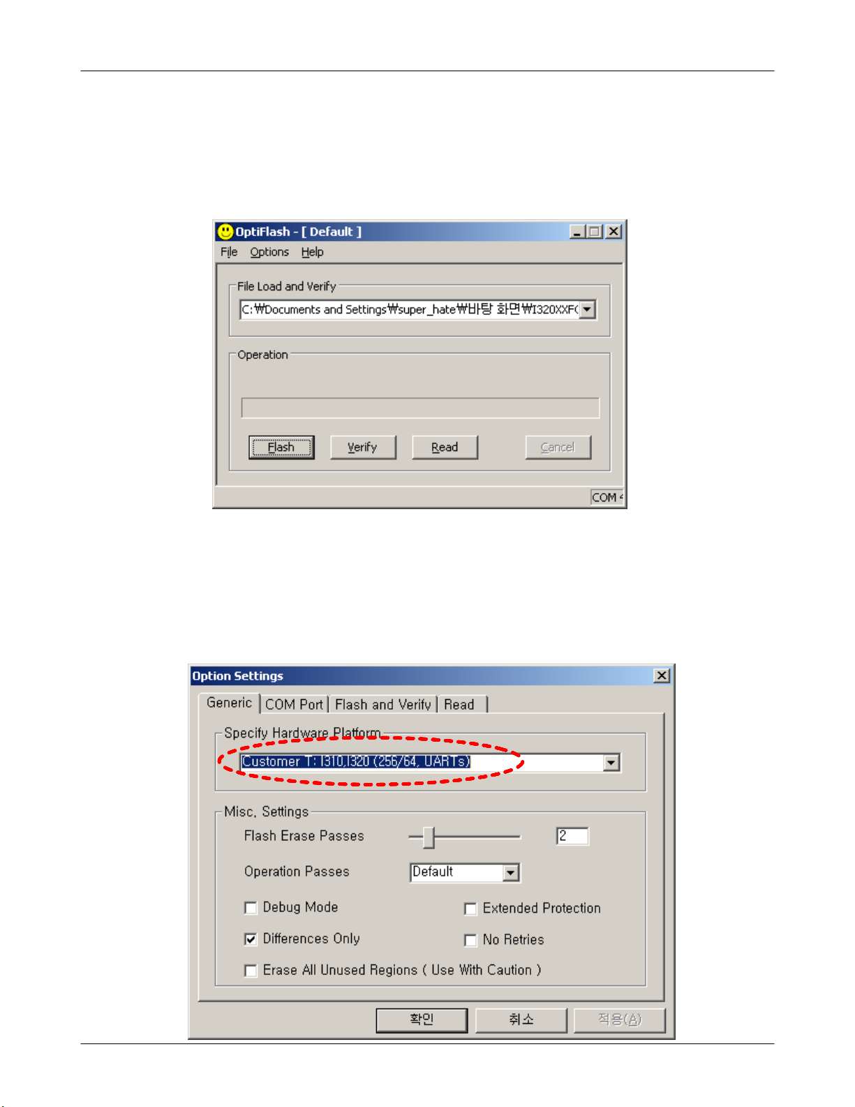
4-3. S/W Downloader Program
1. Load the binary download programby executing the “OptiFlash.exe”
2. Select the “Options” -> “Settings” -> “Generic” -> “Specify hardware
platform”.
Choose hardware platform for the downloader file setting.
Set the everything else as the default values which are shown below
4-3
SAMSUNG Proprietary-Contents may change without notice
This Document can not be used without Samsung's authorization
Array course control
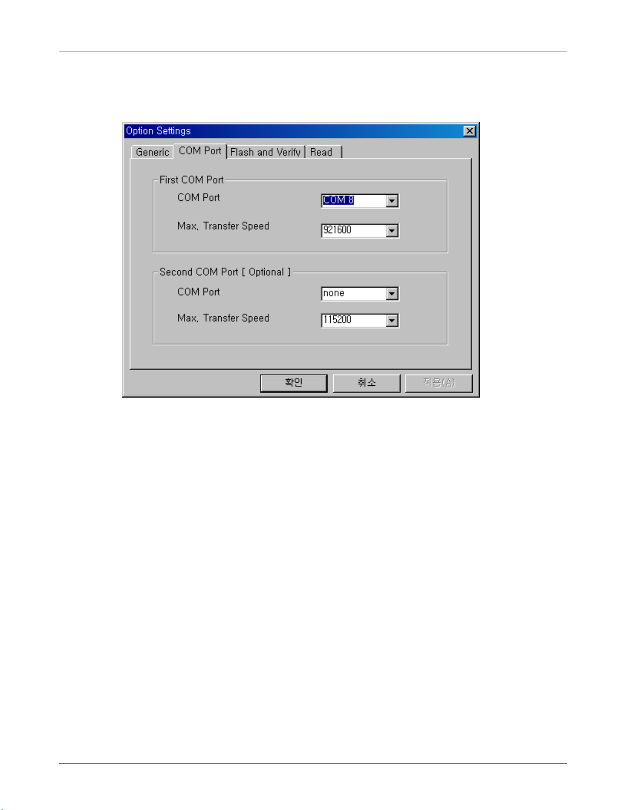
3. Select the COM port when the download cable is connected
Up to twelve ports are supported. Additionally you can select the
maximum transfer speed OptiFlash will use to communicate with
the phone. However, OptiFlash will use a slower speed if either the
PC’s or the phone’s serial hardware is incapable of handling the
selected speed
4-4
SAMSUNG Proprietary-Contents may change without notice
This Document can not be used without Samsung's authorization
Array course control
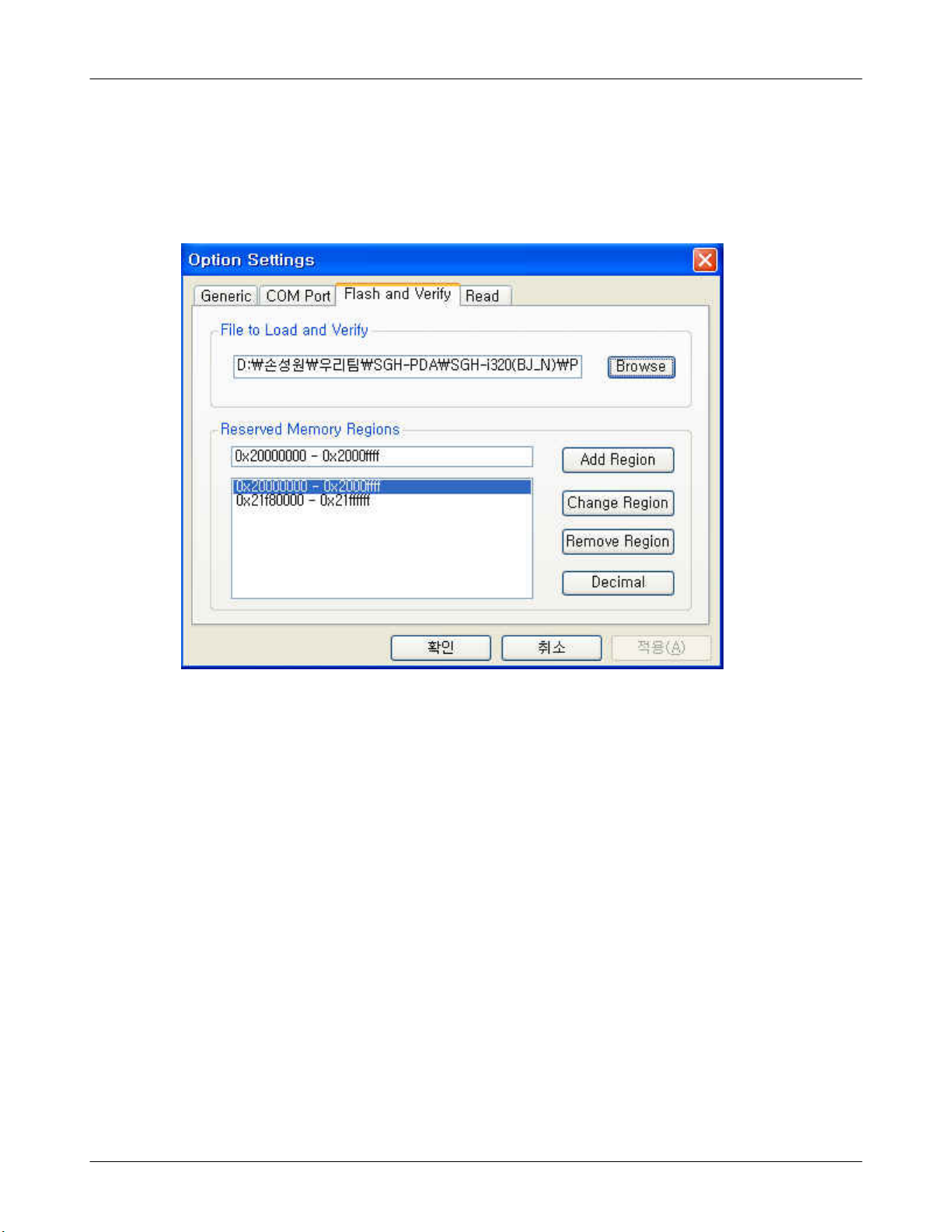
4. Select the“Flash&Verify” -> “Browse”
Set the directory path and choose the latest s/w binary, for example
“I320XXYY.s3”,for the downloader binary setting.
Make sure that not to change the reserved memory
regions.
In case of I320 the reserved regions are :
-0x20000000 – 0x2000ffff
-0x21fe0000– 0x21ffffff
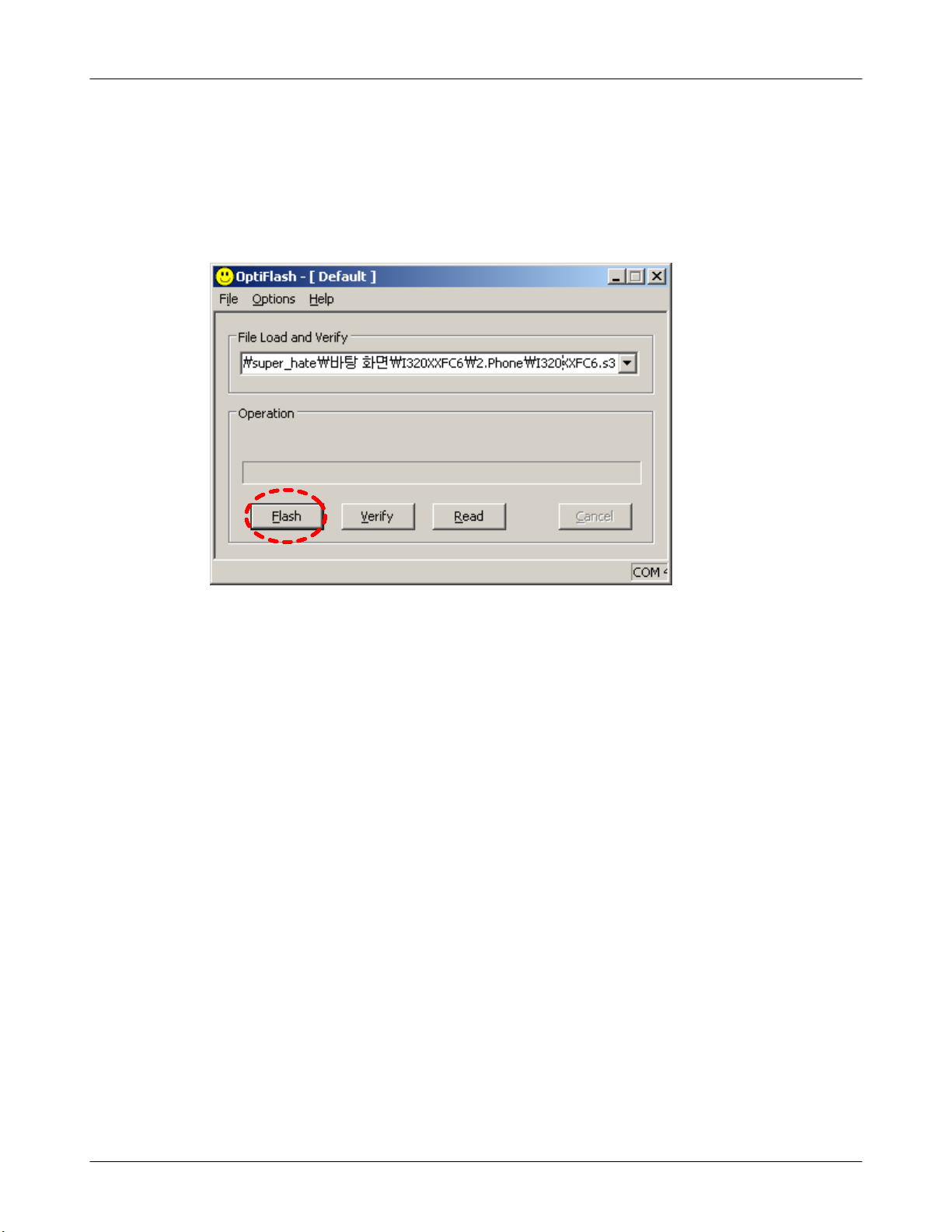
5. Click “OK” button then press “Flash”.
SAMSUNG Proprietary-Contents may change without notice
This Document can not be used without Samsung's authorization
4-5
Array course control
(Before pressing ‘Flash’ button, push the button ‘*’and ‘END’ at the same
time. Then press ‘Flash’.)
Downloader will upload the binary file as below for the downloading.
6. When downloading is finished successfully, there is a “All is well”
message.
7. After finishing downloading, Certain memory resets should b e done to
guarantee the normal performance.
8. Confirm the downloaded version name and etc. :
*#1234#
Full Reset :
*2767*2878#
4-6
SAMSUNG Proprietary-Contents may change without notice
This Document can not be used without Samsung's authorization
5. Exploded View and Parts List
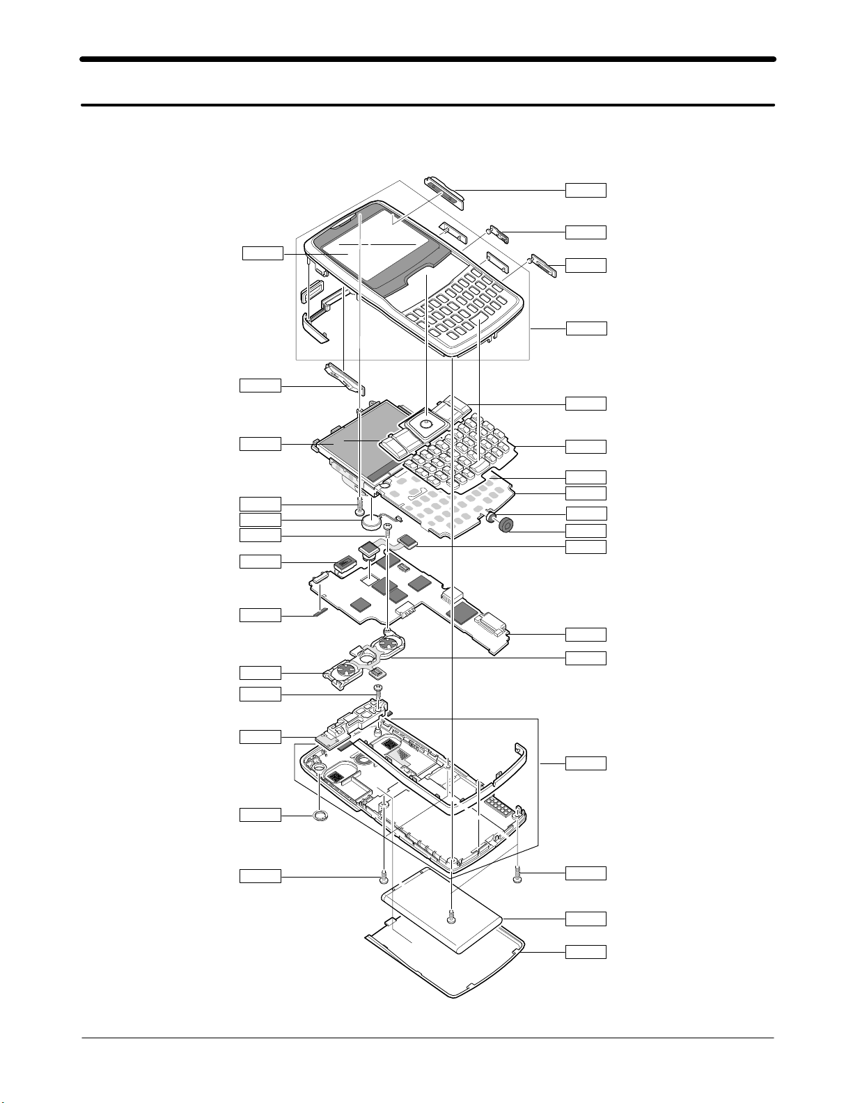
5-1. Cellular phone Exploded View
QMW02
QVO01
QCK01
QRF03
QIF01
QFR01
QKP02
QLC01
QCR12
QMO01
QCR32
QAR01
QAN10
QSP02
QCR04
QAN02
QRF01
QKP01
QME01
QSH01
QMI01
QMI03
QCA01
QMP01
QBR05
QRE01
QCR04
QCR12
QBA01
QBA00
5-1
SAMSUNG Proprietary-Contents may change without notice
This Document can not be used without Samsung's authorization
Exploded View and Parts List
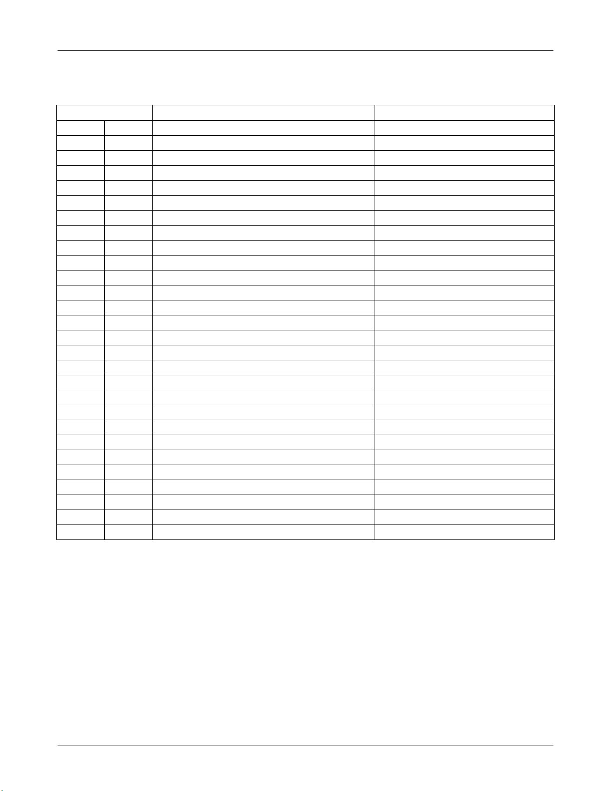
5-2. Cellular phone Parts list
Design LOC Discription SEC CODE
QAN02
QAN10
QAR01
QBA00
QBA01
QBR05
QCA01
QCK01
QCR04
QCR12
QCR32
QKP01
QKP02
QLC01
QMI03
QMO01
QMP01
QMW02
QRE01
QRF01
QSH01
QSP02
QVO01
QME01
QFR01
INTENNA-SGHI320 GH42-00812A
ASSY-CUSHION-ANT CONTACT RUBBE GH98-01218A
AUDIO-RECEIVER 3009-001162
PMO-COVER BATT GH72-28172A
INNER BATTERY PACK-1000MAH,BLA GH43-02424A
ASSY-BRACKET-SPK SHIELD FRAME GH98-01310A
UNIT-CAMERA GH59-02955A
MEC-Q CA KEY GH75-08945A
SCREW-MACHINE 6001-001479
SCREW-MACHINE 6001-001530
SCREW-MACHINE 6001-001700
MEC-KEYPAD MAIN(OPEN/BLK GH75-08942A
ASSY-KEY-KEYPAD SUB GH98-00984A
LCD-SGHI320 GH07-00838A
RMO-CUSHION MIC GH73-06180A
MOTOR DC-SGHI320 GH31-00237A
PBA MAIN-SGHI320 GH92-02504A
PMO-COVER MAIN WINDOW GH72-28151A
MEC-COVER REAR GH75-08944A
PMO-COVER MOBILE GH72-28171A
ASSY-BRACKET-SHIELD BRAKET MAI GH98-00749A
UNIT-SPK FPCB ASSY GH59-02867A
MEC-VOLUME KEY GH75-08946A
UNIT-KEY FPCB GH59-02846A
QMI01 AS-MIC GH81-04513A
MEC-COVER FRONT GH75-08941A
QIF01 PMO-COVER IF GH72-28148A
QRF03 PMO-COVER EAR GH72-28147A
5-2
SAMSUNG Proprietary-Contents may change without notice
This Document can not be used without Samsung's authorization

Exploded View and Parts List
Discription SEC CODE
BAG PE 6902-000634
CBF INTERFACE-DATA LINK CABLE GH39-00564A
CHARGER-SGHE880 TC,EU,BLACK GH44-00998A
CHARGER-SGHI320,BTH GH44-01238A
S/W CD-SGH-I320 MS COMPANION C GH46-00233A
S/W CD-USER MANUAL GH46-00235A
UNIT-EARPHONE GH59-02166A
LABEL(P)-IMEI GH68-01335D
LABEL(P)-WATER SOAK GH68-02026A
LABEL(R)-WATER SOAK T_MOBILE GH68-05914A
MANUAL USERS-QSG FRENCH GH68-09802A
LABEL(R)-MAIN(EU) GH68-09839C
BOX(P)-UNIT MAIN(XET) GH69-03861C
CUSHION-CASE TA2 MA2 GH69-03864A
PMO-COVER FRONT GH72-28143A
RMO-CUSHION BGA A GH73-06184A
RMO-CUSHION BGA B GH73-06185A
RMO-CUSHION BGA D GH73-06187A
RMO-CUSHION BGA E GH73-06188A
RMO-CUSHION PCB GH73-07056A
MPR-DUMMY SHORT TAPE F GH74-11815A
MPR-CUSHION MAIN KEY CON GH74-20153A
MPR-CUSHION MAIN LCD CON GH74-20154A
MPR-CUSHION CAMERA CONN GH74-20156A
MPR-CUSHION SPK CONN GH74-20157A
MPR-CUSHION CAMERA GH74-22450A
MPR-VINYL BOHO MAIN WINDOW A GH74-22788A
MPR-VINYL BOHO MAIN WINDOW B GH74-22789A
MPR-VINYL BOHO KEYPAD GH74-22790A
MPR-SHEET MIC FPCB GH74-23937A
MPR-TAPE IF COVER GH74-23939A
MPR-VINYL BOHO MAIN WINDOW GH74-23940A
MPR-VINYL BOHO BATT COVER GH74-24694A
5-3
SAMSUNG Proprietary-Contents may change without notice
This Document can not be used without Samsung's authorization

6. Disassembly and Assembly instructions
6-1. Disassembly
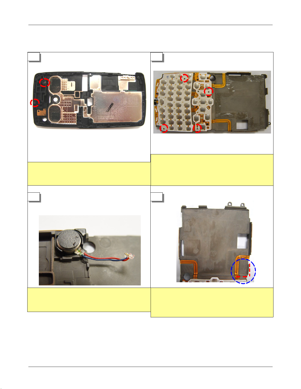
1
1) Put the antenna in the right position caring
about that the hook is properly lock it.
Then screw the antenna.
3 4
2
1) Place and stick the KEY FPCB properly with
checking out that four poles in the red circles
are in the middle of holes of the KEY FPCB.
1) Remove the cover of the tape on the
bottom of the motor, stick the motor on the
frame. Press the motor slightly to stick the
motor firmly.
5 6
1) Remove the cover of the tape on the
bottom of the motor, stick the motor on the
frame. Press the motor slightly to stick the
motor firmly.
6-1
SAMSUNG Proprietary-Contents may change without notice
This Document can not be used without Samsung's authorization
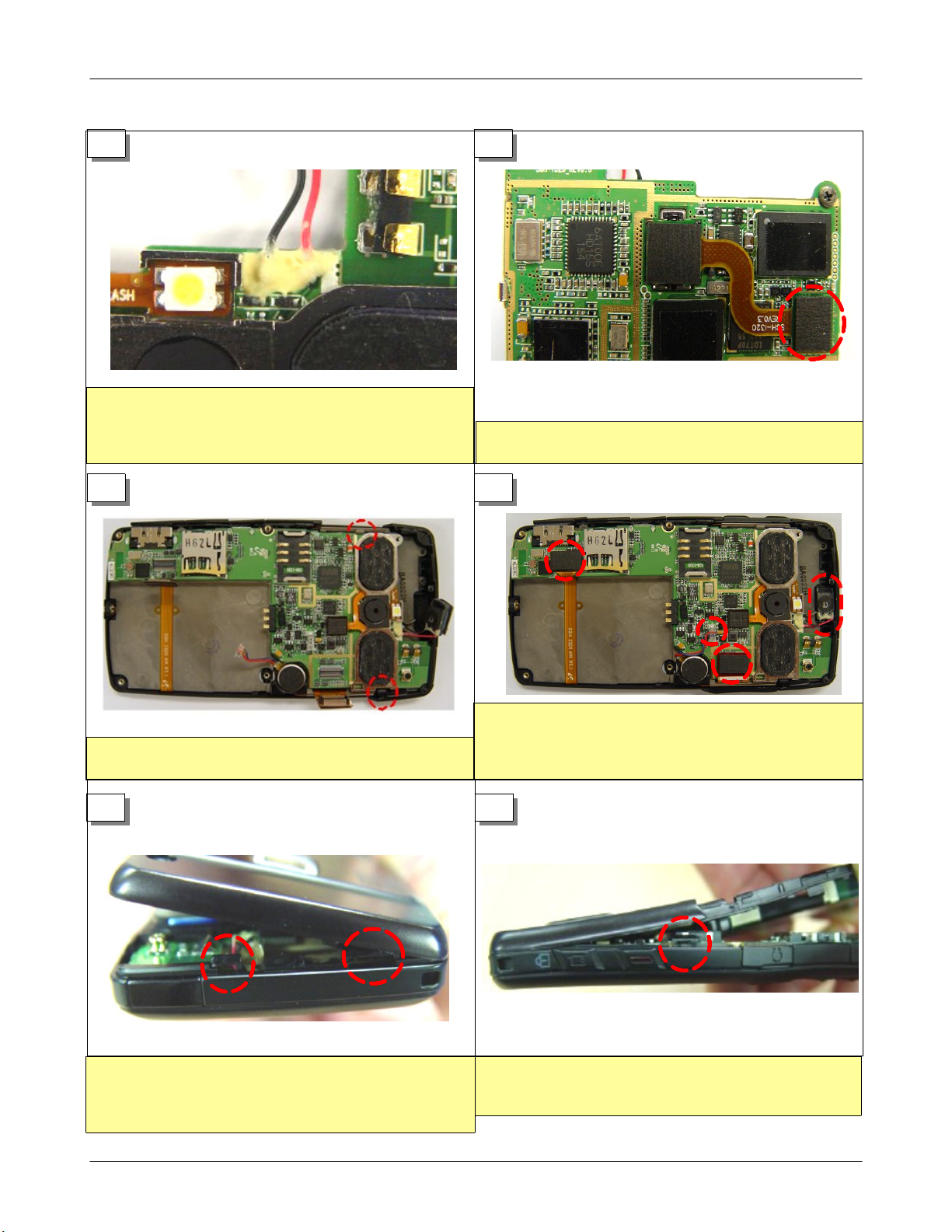
1)Removethecoveronthetapestuckon
the frame insert the LCD connector through
theholeintheframe.Placeandstickthe
bottom right corner of the LCD to the red
guide line in the blue circle.
1) Remove the cover of the tape on the
bottom of the motor, stick the motor on the
frame. Press the motor slightly to stick the
motor firmly.

Disassembly and Assembly instructions
5 6
1) Pull out the receiver and the motor
connector first. the LCD connector and the
key connector later.
7 8
1) Push out two red circled hooks slightly to
lift the PBA.
1) Get rid of the screw in the A red circle.
You can lift the shield frame with pushing out
three hooks slightly.
9 10
...
1) Insert tweezers between the bottom of the
motor and the frame to the direction that the
red arrow directs.
6-2
1) Remove the sponge on the LCD connector
first, then you can detach the LCD from the
frame.
1) Take off the KEY FPCB with care not to
damage KEY FPCB.
SAMSUNG Proprietary-Contents may change without notice
This Document can not be used without Samsung's authorization

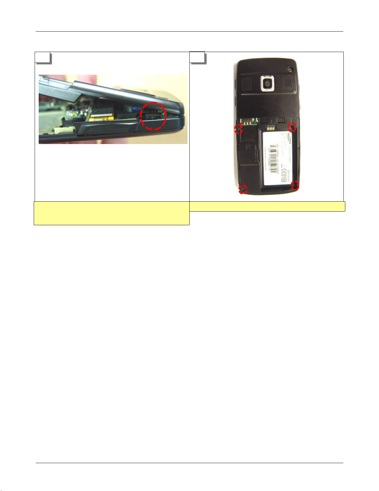
11
...
1) Remove two screws in the red circles and
take out the antenna with care not to damage
the hook..
Disassembly and Assembly instructions
6-3
SAMSUNG Proprietary-Contents may change without notice
This Document can not be used without Samsung's authorization
6-2. Assembly
Disassembly and Assembly instructions
1
1) Get rid of 4 screws in the red circled
corners. Be careful not to damage the rear
cover.
3 4
2
1) Lift the rear cover slightly and unlock the
hook on the left side(the upper part of ear
jack cover) of the rear cover. Be careful not
to damage the rear cover or the hook.
1) Remove the cover of the tape on the
bottom of the motor, stick the motor on the
frame. Press the motor slightly to stick the
motor firmly.
SAMSUNG Proprietary-Contents may change without notice
This Document can not be used without Samsung's authorization
1)Removethecoveronthetapestuckon
the frame insert the LCD connector through
theholeintheframe.Placeandstickthe
bottom right corner of the LCD to the red
guide line in the blue circle.
6-4

Disassembly and Assembly instructions
5 6
1) Stick the sponge in the guideline oh the
LCD connector with care.
7 8
A
1) Place the frame on the right position and
lock three hooks in the red circle. Screw the
frame in the red A circle.
9 10
1) Place the key pad properly minding guide
poles on the front cover.
1) Solder the receiver on the PCB minding
silk marks of soldering pads on the PCB. Be
careful not to cause a short-circuit when you
solder.
...
1) Insert a rubber into the antenna contact
with care not to damage antenna contact with
a pair of tweezers.
SAMSUNG Proprietary-Contents may change without notice
This Document can not be used without Samsung's authorization
1) Put together the speaker assembly and
screw in the right red circle. Then put the
speaker connector on the connector on the
PBA.
6-5
11 12
1) Put some adhesive on the soldered motor
wire. Be careful not to get an adhesives on
the antenna contact or the flash LED near the
motor wire.
1) Put the camera connector on the connector
on the PBA firmly.
13 14
Disassembly and Assembly instructions
1) Put on the receiver into the hole of the
front cover, the receiver connector, the motor
1) Place the PBA pushing out two hooks in
the red circles slightly.
connector, the LCD connector, and the key
connector on the right positions firmly.
15 16
1)Putsidekeysontherightdirections,then
lock two hooks on the top of the rear cover.
After locking two hooks, press the rear cover
slightly to assemble two covers.
1) Press the rear cover part around the red
circle area slightly to lock the left hook on
the rear cover.
6-6
SAMSUNG Proprietary-Contents may change without notice
This Document can not be used without Samsung's authorization
Disassembly and Assembly instructions
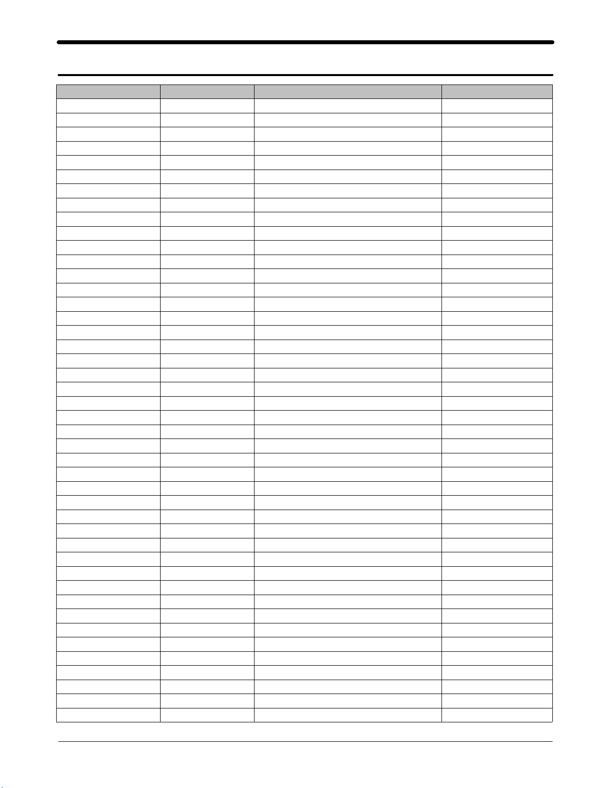
17
1) Press the rear cover part around the red
circle area slightly to lock the rightt hook on
the rear cover.
18
1) Screw four positions in the red circles.
6-7
SAMSUNG Proprietary-Contents may change without notice
This Document can not be used without Samsung's authorization
7. MAIN Electrical Parts List
SEC CODE Design LOC Discription STATUS
4202-001131 ANT1001 ANTENNA-CHIP SA
GH71-06419A ANT1800 NPR-ANTENNA CONTACT SA
GH71-06419A ANT900 NPR-ANTENNA CONTACT SA
4302-001158 BAT701 BATTERY-LI(2ND) SA
3711-006003 BTC301 CONNECTOR-BATTERY SA
2203-006423 C1001 C-CER,CHIP SA
2203-006824 C1003 C-CER,CHIP SA
2203-006048 C1004 C-CER,CHIP SA
2203-006048 C1005 C-CER,CHIP SA
2203-006423 C101 C-CER,CHIP SA
2203-006257 C1012 C-CER,CHIP SA
2203-006562 C1013 C-CER,CHIP SA
2203-000254 C1014 C-CER,CHIP SA
2203-006423 C102 C-CER,CHIP SA
2203-000438 C1027 C-CER,CHIP SA
2203-006305 C1028 C-CER,CHIP SA
2203-006423 C103 C-CER,CHIP SA
2203-006423 C1031 C-CER,CHIP SA
2203-000386 C1034 C-CER,CHIP SA
2203-006121 C1036 C-CER,CHIP SA
2203-000425 C1038 C-CER,CHIP SA
2203-006423 C104 C-CER,CHIP SA
2203-006423 C105 C-CER,CHIP SA
2203-006423 C106 C-CER,CHIP SA
2203-006423 C107 C-CER,CHIP SA
2203-006423 C108 C-CER,CHIP SA
2203-006423 C109 C-CER,CHIP SA
2203-006423 C110 C-CER,CHIP SA
2203-006423 C111 C-CER,CHIP SA
2203-006423 C112 C-CER,CHIP SA
2203-006423 C113 C-CER,CHIP SA
2203-006423 C114 C-CER,CHIP SA
2203-006423 C115 C-CER,CHIP SA
2203-006423 C117 C-CER,CHIP SA
2203-006423 C118 C-CER,CHIP SA
2203-006423 C119 C-CER,CHIP SA
2203-006423 C120 C-CER,CHIP SA
2203-006423 C121 C-CER,CHIP SA
2203-006423 C122 C-CER,CHIP SA
2203-006423 C123 C-CER,CHIP SA
2203-006423 C124 C-CER,CHIP SA
2203-006423 C125 C-CER,CHIP SA
2203-006423 C126 C-CER,CHIP SA
2203-006423 C127 C-CER,CHIP SA
1
7-
SAMSUNG Proprietary-Contents may change without notice
This Document can not be used without Samsung's authorization
 Loading...