

Samsung SGH-F700V service manual
GSM TELEPHONE
SGH-F700V
GSM TELEPHONE
CONTENTS
1. Safety Precautions
2. Specification
3. Product Function
4. Array course control
5. Exploded View and Parts List
6. Main Electrical Parts List
7. Block Diagrams
8. PCB Diagrams
9. Flow Chart of Troubleshooting
10. Reference data
11. Disassembly and Assembly
Instructions
GSPN (Global Service Partner Network)
Country Web Site
North America service.samsungportal.com
Latin America latin.samsungportal.com
CIS cis.samsungportal.com
Europe europe.samsungportal.com
China china.samsungportal.com
Asia asia.samsungportal.com
Mideast & Africa mea.samsungportal.com
This Service Manual is a property of Samsung Electronics Co.,Ltd.
Any unauthorized use of Manual can be punished under applicable
International and/or domestic law.
ⓒ
Samsung Electronics Co.,Ltd.
2007. 10. Rev.1.0
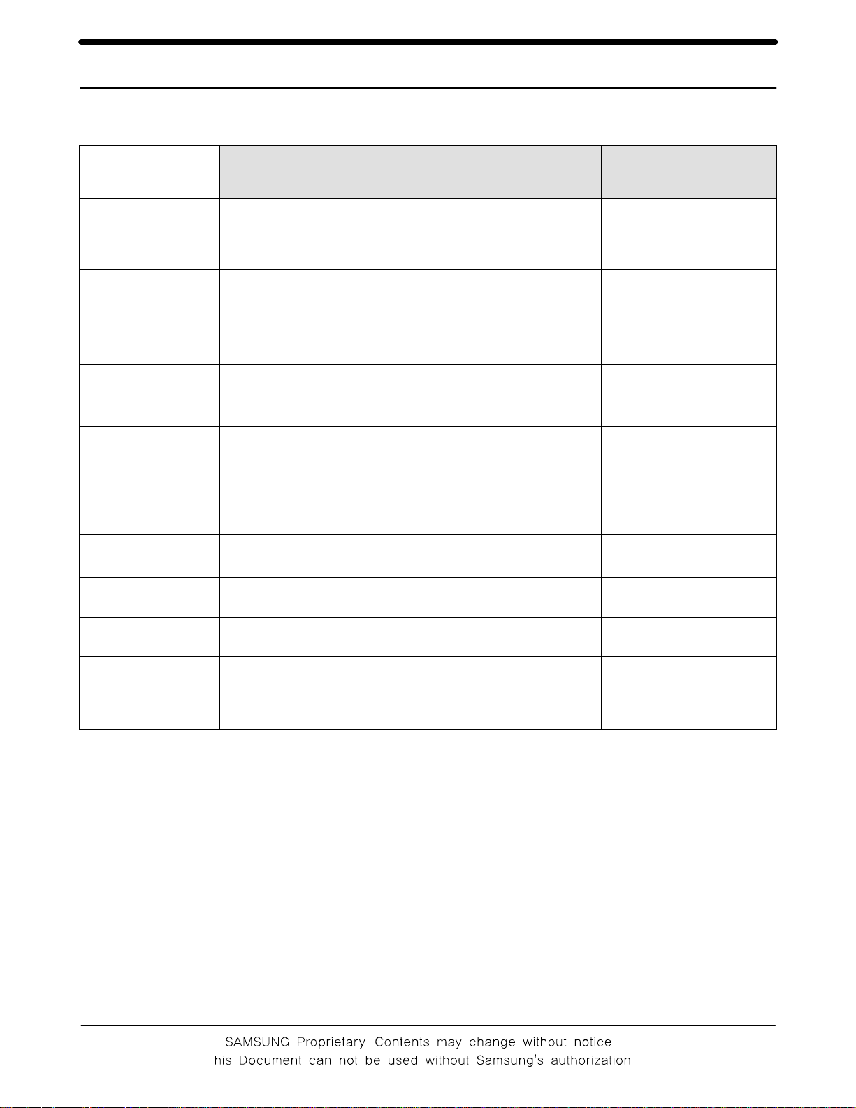
2. Specification
2-1. GSM General Specification
EGSM 900 DCS 1800 PCS 1900 WCDMA2100
Freq.
Band[MHz]
Uplink/Downlink
ARFCN range
Tx/Rx spacing 45MHz 95MHz 80MHz 190MHz
Mod. Bit rate/
Bit Period
Time Slot
Period/Frame
Period
Modulation 0.3GMSK 0.3GMSK 0.3GMSK
MS Power 33dBm~5dBm 30dBm~0dBm 30dBm~0dBm 24dBm~ -50dBm
Power Class
880~915
925~960
0~124 &
975~1023
270.833kbps
3.692us
576.9us
4.615ms
4
(max +33dBm)1(max +30dBm)
1710~1785
1805~1880
512~885 512~810
270.833kbps
3.692us
576.9us
4.615ms
1850~1910
1930~1990
270.833kbps
3.692us
576.9us
4.615ms
1
(max +30dBm)
1920~1980
2110~2170
UL:9612~9888
DL:10562~10838
3.84Mcps
Frame length : 10ms
Slot length: 0.667ms
QPSK
HQPSK
3
(max +24dBm)
Sensitivity -102dBm -100dBm -100dBm -106.7dBm
TDMA Mux 8 8 8 NA
Cell Radius 35Km 2Km 2Km 2Km
2-1
Speclflcation
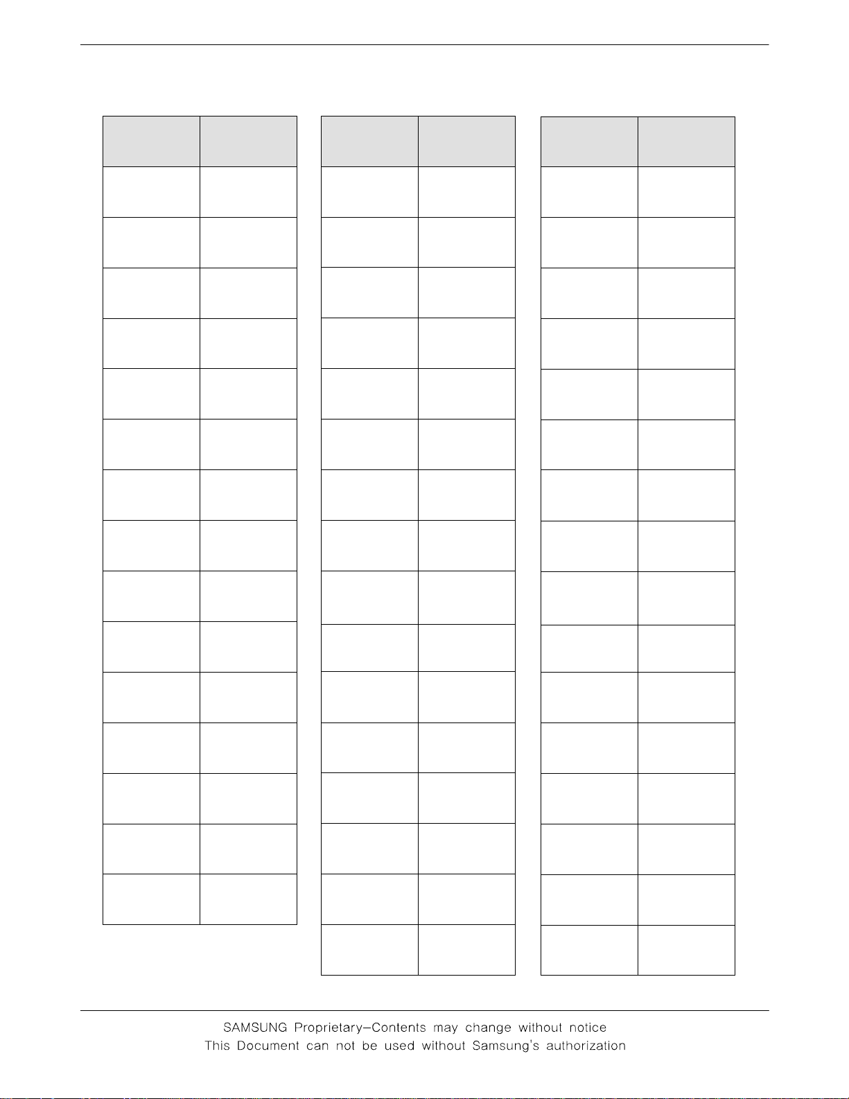
2-2. GSM Tx Power Class
TX Power
control level
533±2dBm
631±2dBm
729±2dBm
827±2dBm
925±2dBm
10 23±2 dBm
11 21±2 dBm
GSM900
TX Power
control level
030±3dBm
128±3dBm
226±3dBm
324±3dBm
422±3dBm
520±3dBm
618±3dBm
DCS1800
TX Power
control level
030±3dBm
128±3dBm
226±3dBm
324±3dBm
422±3dBm
520±3dBm
618±3dBm
PCS1800
12 19±2 dBm
13 17±2 dBm
14 15±2 dBm
15 13±2 dBm
16 11±3 dBm
17 9±3dBm
18 7±3 dBm
19 5±3 dBm
716±3dBm
814±3dBm
912±4dBm
10 10±4 dBm
11 8±4dBm
12 6±4 dBm
13 4±4 dBm
14 2±5 dBm
716±3dBm
814±3dBm
912±4dBm
10 10±4 dBm
11 8±4dBm
12 6±4 dBm
13 4±4 dBm
14 2±5 dBm
15 0±5 dBm
2-2
15 0±5 dBm
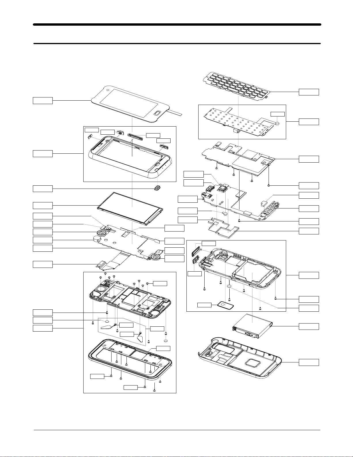
5. Exploded View and Parts List
5-1. Cellular phone Exploded View
QME02
QCK02
QCK03
QVO01
QCK01
QKP01
QMI01
QME01
QFU01
QVO03
QLC01
QCA02
QVK02
QSP01
QMO01
QMP02
QPC01
QCR21
QSC05
QFL01
QHI25
QHI18
QCR57
QHI01
QVK01
QCA10
QVK04
QSP02
QCA01
QMP01
QVK08
QMI01
QSH01
QRF03
QIF01
QCW01
QBR01
QCR57
QAN05
QAN02
QCR08
QSH02
QRE01
QCR07
QRF01
QBA01
QFR01
QCR58
QCR61
5-4
SAMSUNG Proprietary-Contents may change without notice
This Document can not be used without Samsung's authorization
QBA00

Exploded View and Parts List
5-2. Cellular phone Parts List
Design LOC Description SEC CODE
QAN02 INTENNA-SGHF700 GH42-01344A
QAN05 RMO RUBBER-INTENNA GH73-11265A
QBA00 ASSY CASE-BATTERY GH98-07075A
QBA01 INNER BATTERY PACK-1000MAH,BLK GH43-02974A
QBA02 PMO COVER-BATTERY GH72-45829A
QBR01 ASSY BRACKET-SHIELD GH98-06469A
QCA01 CAMERA MODULE-3M 1/4'' GH59-04630A
QCA02 CAMERA MODULE-VGA 1/7.4'' GH59-04631A
QCA10 KEY FPCB-CAMERA KEY GH59-04985A
QCK01 PMO KEY-CAMERA V3 GH72-43728A
QCK02 PMO KEY-POWER V3 GH72-43726A
QCK03 PMO KEY-HOLD V3 GH72-43725A
QCR07 SCREW-MACHINE 6001-001691
QCR08 SCREW-MACHINE 6001-001456
QCR21 SCREW-MACHINE 6001-001507
QCR47 SCREW-MACHINE 6001-001695
QCR57 SCREW-MACHINE 6001-002001
QCR57 SCREW-MACHINE 6001-002001
QCR61 SCREW-MACHINE 6001-002008
QCW01 ASSY DECO-WINDOW CAMERA GH98-06470A
QFL01 ASSY CASE-SLIDE LOWER GH98-06217A
QFR01 ASSY CASE-FRONT GH98-06214A
QFU01 ASSY CASE-SLIDE UPPER GH98-06213A
QHI01 ASSY HINGE-SLIDE GH98-06216A
QHI18 ASSY HINGE-SINGLE LINK L GH98-06610A
QHI25 ASSY HINGE-SINGLE LINK R GH98-06611A
QIF01 PMO COVER-IF V4 GH72-44306A
QKP01 ASSY KEYPAD-(SFR/BLU) GH98-07007A
QLC01 LCD-SGHF700 GH07-01195A
QME01 KEY FPCB-TF KEY GH59-04988A
QME02 UNIT-TOUCH SCREEN (OPEN) GH59-05299A
QMI01 MICROPHONE-ASSY-SGHF700 GH30-00426A
QMI01 AS-SCHR200 MIC GH81-06811A
QMO01 MOTOR LINEAR VIBRATION-SGHF700 GH31-00380A
QMP01 PBA MAIN-SGHF700 GH92-03562A
QMP02 PBA SUB-SGHF700 GH92-03571A
QPC01 FPC-SLIDEFPCB GH41-01884A
QRE01 ASSY CASE-REAR GH98-06215A
QRF01 TAPE-RF SHEET GH74-35528A
QRF03 PMO COVER-EAR GH72-44269A
QSC05 TAPE-LOWER SCREW CAP GH74-35519A
5-2
SAMSUNG Proprietary-Contents may change without notice
This Document can not be used without Samsung's authorization
Exploded View and Parts List
QSH01 ICT SHIELD-A GH70-02965A
QSH02 ICT SHIELD-B GH70-02966A
QSP01 MICRO SPEAKER 3001-002277
QSP02 MICRO SPEAKER 3001-002278
QVK01 KEY FPCB-SIDE KEY FPCB(VK) GH59-04983A
QVK02 KEY FPCB-SIDE KEY FPCB(PK) GH59-04984A
QVK04 KEY FPCB-SIDE KEY FPCB(HK) GH59-04982A
QVK08 ASSY ETC-SGH-F700 EARJACK FPCB GH59-05012A
QVO01 PMO KEY-VOLUME V3 GH72-43727A
QVO03 PMO KEY-HOME GH72-44223A
5-3
SAMSUNG Proprietary-Contents may change without notice
This Document can not be used without Samsung's authorization
Exploded View and Parts List
CBF INTERFACE-DLC APCBS10BBE(S GH39-00922A
CBF INTERFACE-MIC CABLE(S20P,B GH39-00986A
ADAPTOR-ATADS10EBE,BLK,EU GH44-01702A
EARPHONE-EARPHONE,3 PLUG,BLK,E GH59-04418A
S/W CD-SGHF700 SAMSUNG PC 3.2 GH46-00540A
MANUAL USERS-VDPN FRENCH GH68-16613A
Description SEC CODE
RMO RUBBER-LCD GH73-11264A
VINYL-MAIN WINDOW GH74-36206A
TAPE INSU-CONN GH74-36211A
TAPE INSU GH74-36214A
TAPE INSU GH74-36433A
TAPE-FPCB GH74-36029A
TAPE INSU GH74-36627A
TAPE-HOLD GH74-36633A
TAPE GASK GH74-36401A
TAPE-FPCB GH74-36029A
SPONGE GH74-36993A
LABEL(R)-WATER SOAK GH68-09361A
BAG PE 6902-000634
LABEL(P)-UNIT SEAL GH68-00518B
LABEL(R)-MAIN(VODA_FRAN) GH68-16384B
BOX-UNIT(SFR) GH69-06048B
CUSHION-CASE(VODA) GH69-06049A
VINYL-WINDOW GH74-36678A
5-4
SAMSUNG Proprietary-Contents may change without notice
This Document can not be used without Samsung's authorization
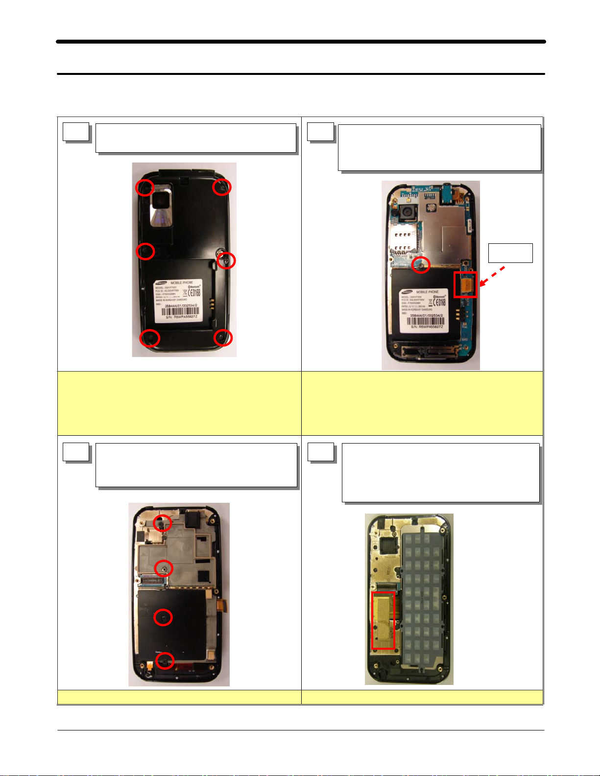
11. Disassembly and Assembly Instructions
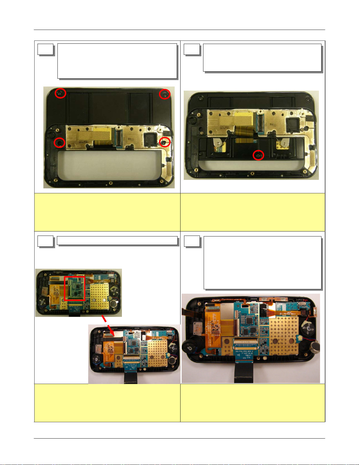
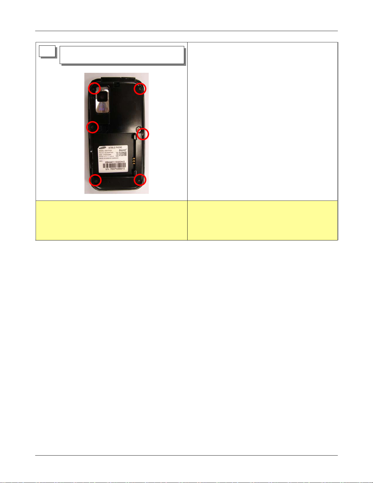
11-1. Disassembly Instructions
1) RELEASE SCREWS AT 6 POINT.
1
2) DISASSEMBLE REAR CASE.
2
1) RELEASE THE FIXED SCREW OF MAIN PBA.
(1 POINT)
2) DISASSEMBLE KEY CONNECTOR.
3) DISASSEMBLE MAIN PBA.
KEY
CONNECTOR
1) DO NOT MAKE SCRATCH ON CASE.
1) RELEASE THE FIXED SCREW OF SHIELD CAN.
3
(4 POINT)
2) DISASSEMBLE SHIELD CAN.
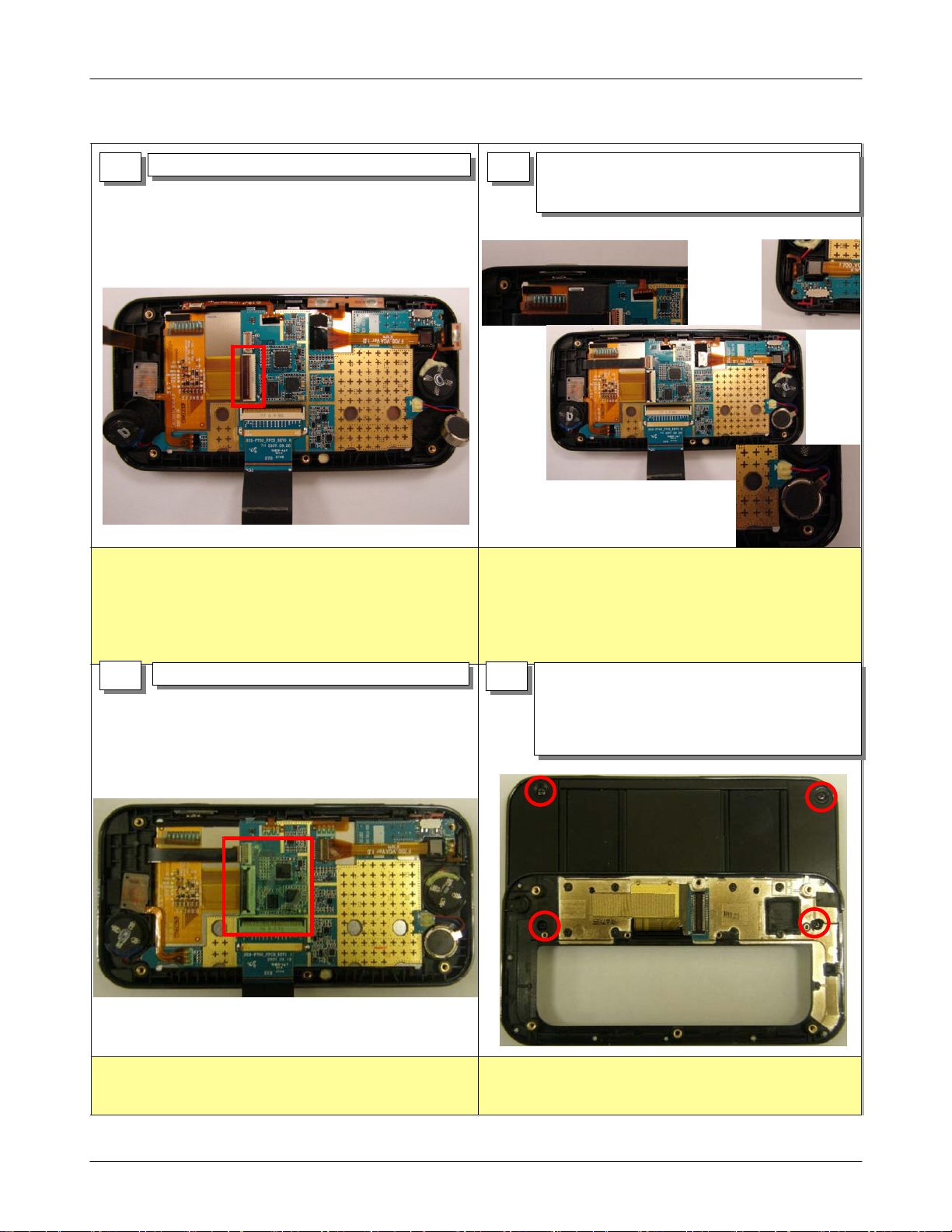
1) WHEN YOU DISASSEMBLE KEY CONNECTOR,
TAKE CARE NOT TO DAMAGE F-PCB.
1) DISASSEMBLE KEY PAD.
4
2) DETACH THE FIXED GASKET TAPE OF SLIDE
F-PCB.
3) PUSH SLIDE RIGHT SIDE.
11-1
SAMSUNG Proprietary-Contents may change without notice
This Document can not be used without Samsung's authorization
Disassembly and Assembly Instructions
1) DETACH THE SCREW CAP OF LOWER CASE.
5 6
(2 POINT)
2) DISASSEMBLE SLIDE ASS'Y AND RELEASE THE
FIXED SCREW OF UPPER CASE. (3 POINTS)
1) DO NOT MAKE SCRATCH ON CASE.
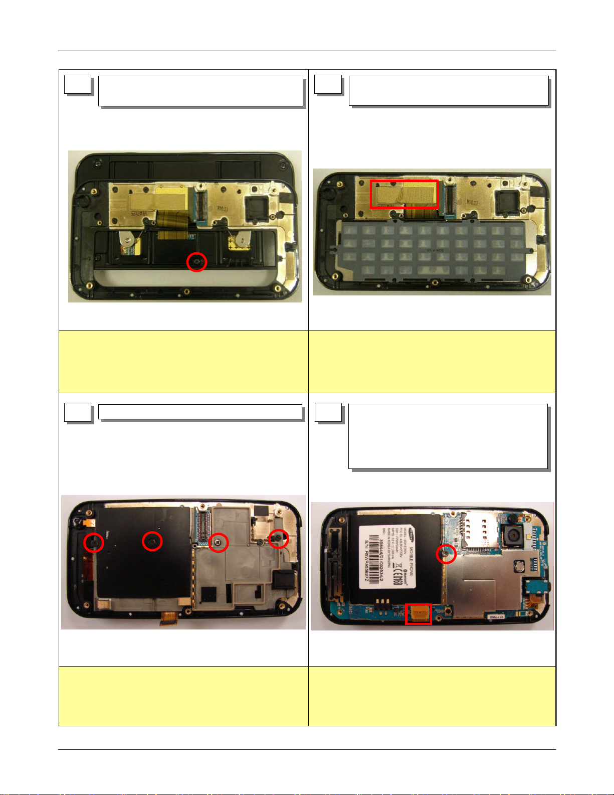
1) PUSH SLIDE INSIDE SLIGHTLY.
2) DISASSEMBLE SLIDE ASS'Y AND RELEASE
THE FIXED SCREW OF UPPER CASE.(2 POINT)
3) DISASSEMBLE SLIDE ASS'Y.
1) PLEASE MAKE SURE THAT THE F-PCB IS LOCATED IN THE
MIDDLE OF SLOT.(OTHERWISE F-PCB WILL BE DAMAGED.)
1) DETACH INSULATION TAPE.
7 8
1) BE CAUTIOUS NOT TO DAMAGE TO COMPONENTS BY
PINCETTE.
1) DISASSEMBLE LCD F-PCB AND TOUCH KEY
F-PCB.
2) DISASSEMBLE SPEAKER(2EA) AND MOTOR(1EA).
3) USING PINCETTE, DISASSEMBLE POWER KEY,
VOLUME KEY, CAMERA KEY, HOME KEY, SUB
CKAMERA.
1) WHEN EACH SUB COMPONENTS ARE DISASSEMBLED,
BE CAUTIOUS NOT TO DAMAGE TO COMPONENTS.
11-2
SAMSUNG Proprietary-Contents may change without notice
This Document can not be used without Samsung's authorization
9
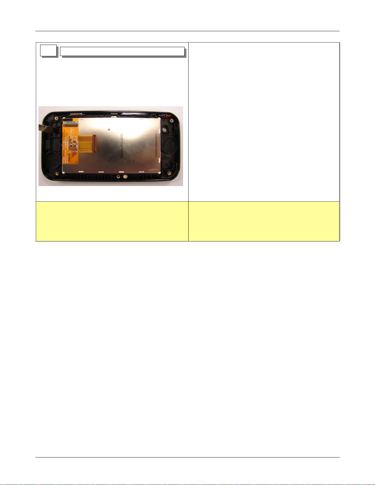
1) DISASSEMBLE SUB PCB.
Disassembly and Assembly Instructions
1) LCD CONNECTOR가 손상가지 않도록 주의한다.
1) 양면테잎으로 LCD 모듈이 고정되어 있으므로 분리 시
주의한다.
11-3
SAMSUNG Proprietary-Contents may change without notice
This Document can not be used without Samsung's authorization
Disassembly and Assembly Instructions
11-2. Assembly Instructions
1) CONNECT LCD F-PCB TO SUB PBA.
1 2
1) WHEN THE LCD F-PCB IS INSERTED,
TAKE CARE NOT TO DAMAGE F-PCB.
1) ATTACH INSULATION TAPE CORRECTLY.
3
1) CONNECT TOUCH KEY F-PCB.
2) I N S ER T SPEAKER(2EA), MOTOR KEY, HOME KEY,
,POWER KEY,VOLUME KEY,CKAMERA KEY.
THE CAMERA KEY F-PCB MUST INSERT CORRECTLY
1)
INSIDE OF GUIDELINE.
2) TAKE CARE NOT TO TWIST ALL OF WIRES.
3) THE HOLD KEY MUST INSERT CORRECTLY INSIDE OF HALL
GUIDELINE.
1) PASS SLIDE F-PCB THROUGH SLIDE ASS'Y.
4
2) ASSEMBLE UPPER CASE AND SLIDE ASS'Y.
3) DRIVE SCREWS AT 3 POINT.
4) ATTACH SCREW CAPS AT 2 POINT.
1)
BE CAUTIOUS NOT TO DAMAGE TO COMPONENTS BY
PINCETTE.
SAMSUNG Proprietary-Contents may change without notice
This Document can not be used without Samsung's authorization
1) DO NOT MAKE SCRATCH ON CASE.
11-4
Disassembly and Assembly Instructions
1) SLIDE UP SLIGHTLY.
5 6
2) DRIVE SCREWS AT 2 POINT.
1) PLEASE MAKE SURE THAT THE F-PCB IS LOCATED IN THE
MIDDLE OF SLOT.(OTHERWISE F-PCB WILL BE DAMAGED.)
1) ATTACH CONDUCTION GASKET.
2) INSERT CORRECTLY KEY PAD.
1) DRIVE SCREWS AT 4 POINT.
7 8
1) WHEN YOU ASSEMBLE,BE CAREFUL NOT TO DESTROY THE
SHIELD GASKET.
2) USE AN AIR GUN NOT TO LEAVE ANY PARTICLE ON LCD
CONNECTOR.
1) ATTACH MAIN PBA.
1. AT FIRST, ATTACH MAIN CAMERA.
2. TURN 180°THE EARJACK THEN INSERT IT.
2) ASSEMBLE KEY CONNECTOR.
3) DRIVE SCREWS AT 1 POINT.
1) WHEN LCD CONNECTOR IS ASSEMBLED, CHECK IT OUT
THERE IS "TICK' SOUND.
2) WHEN YOU DRIVE SCREWS, TAKE CARE NOT TO TOUCH THE
COMPONENTS.
11-5
SAMSUNG Proprietary-Contents may change without notice
This Document can not be used without Samsung's authorization
Disassembly and Assembly Instructions
ASSEMBLE REAR CASE.
1)
9
DRIVE SCREWS AT 6 POINT.
2)
1) FIRSTLY, DRIVE SCREWS FROM THE BOTTOM ONES TO TOP
ONES.
2) DO NOT MAKE SCRATCH ON CASE.
11-6
SAMSUNG Proprietary-Contents may change without notice
This Document can not be used without Samsung's authorization
9. Flow Chart of Troubleshooting
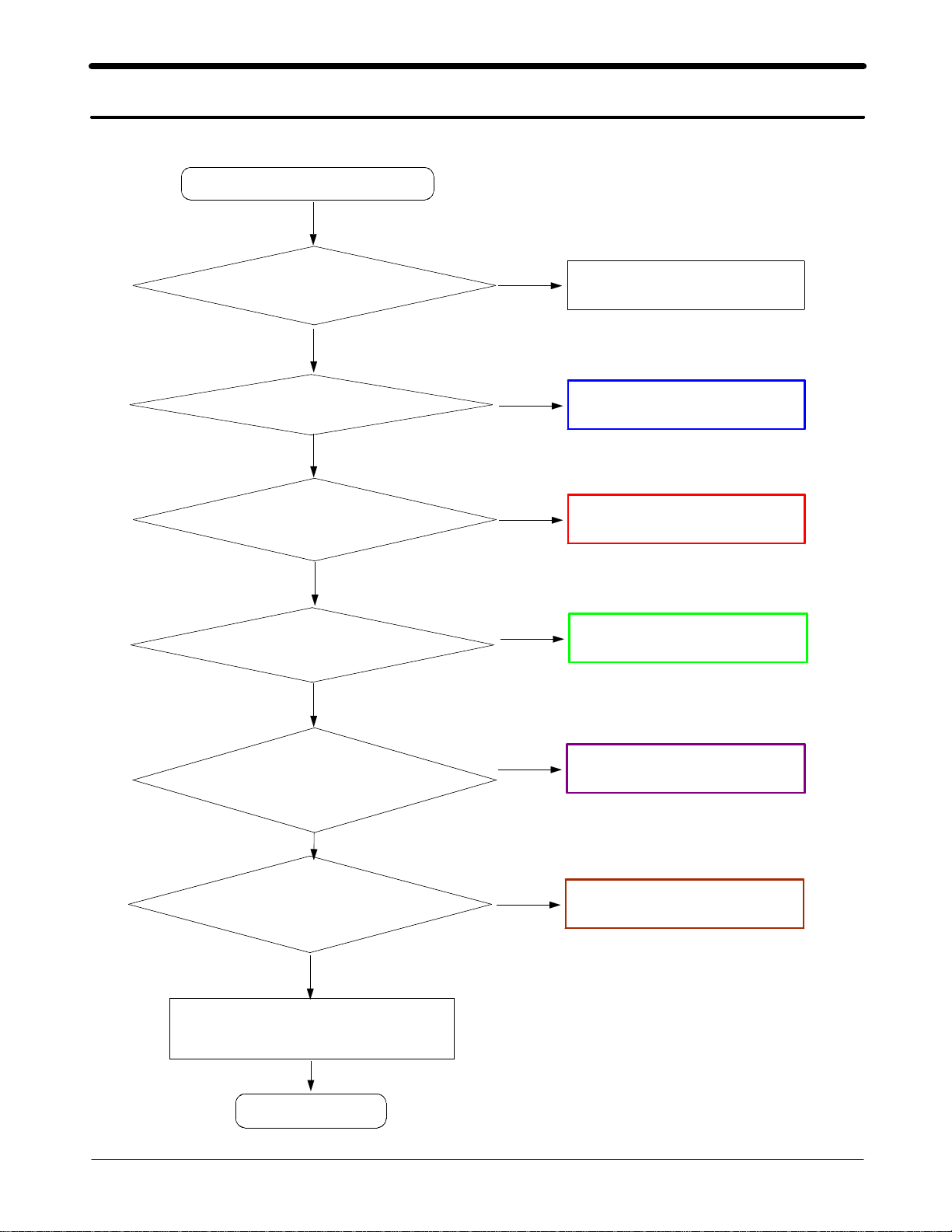
9-1. Power On
' Power On ' does not work
Yes
Check the Battery Voltage
is more than 3.4V
Yes
U302 pin F10(PS_HOLD)
L300(VREG_MSMC)=1.2V?
=2.6V?
Yes
Check the Clock at
OSC300=32.768KHz
Yes
Yes
No
Change the Battery
No
Check the U302 related to PS_HOLD
No
Resolder OSC300
No
Check the PMIC
R302(VREG_MSME)=1.8V?
R301(VREG_MSMP)=2.6V?
R300(VREG_MSMA)=2.6V?
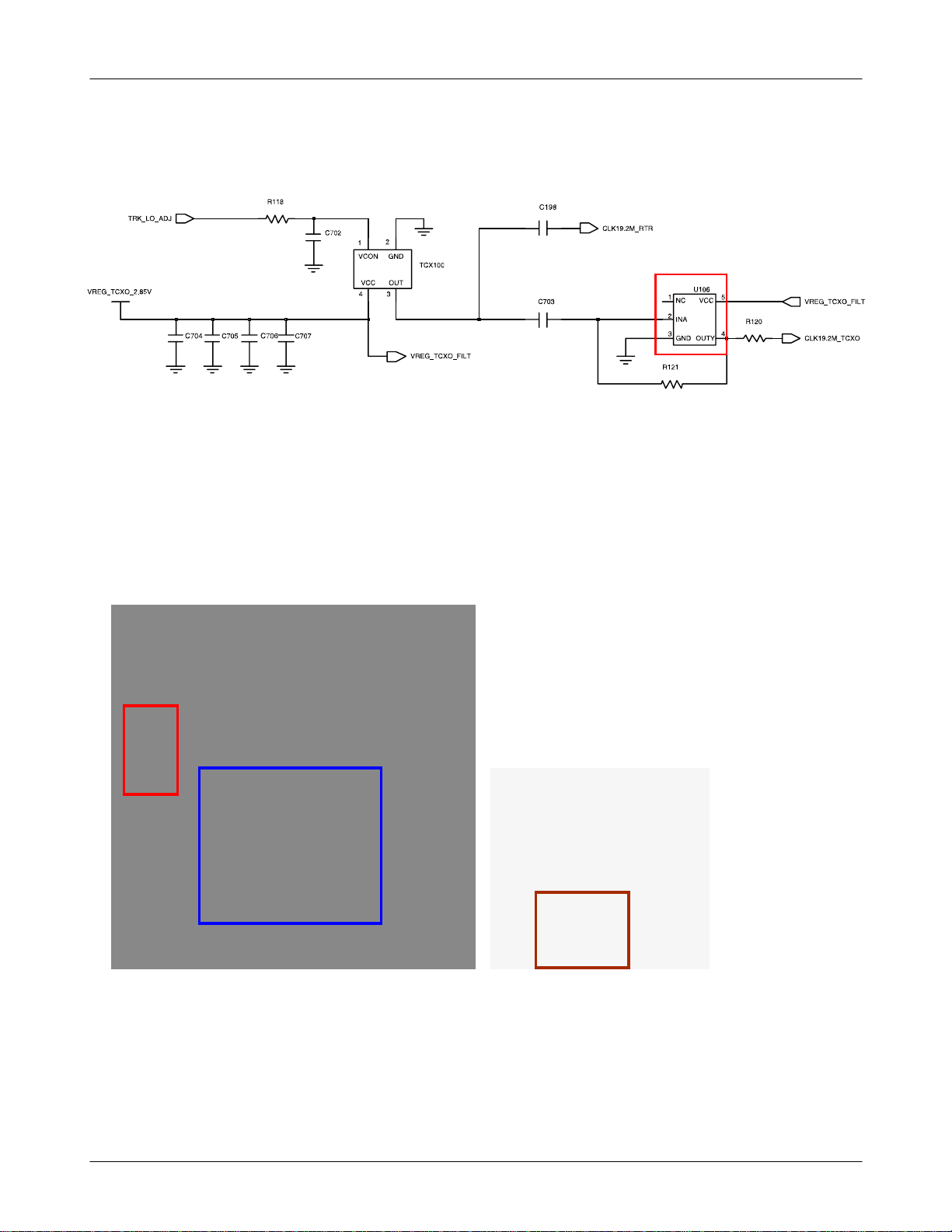
C325(VREG_TCXO)=2.8V?
Yes
Check for the clock at C327
=19.2MHz
Yes
Check the initial operation
Yes
END
SAMSUNG Proprietary-Contents may change without notice
This Document can not be used without Samsung's authorization
9-1
No
No
Check the PMIC
Check the clock generation circuit
(related to U106)

Flow Chart of Troubleshooting
9-2
SAMSUNG Proprietary-Contents may change without notice
This Document can not be used without Samsung's authorization
Flow Chart of Troubleshooting
9-3
SAMSUNG Proprietary-Contents may change without notice
This Document can not be used without Samsung's authorization
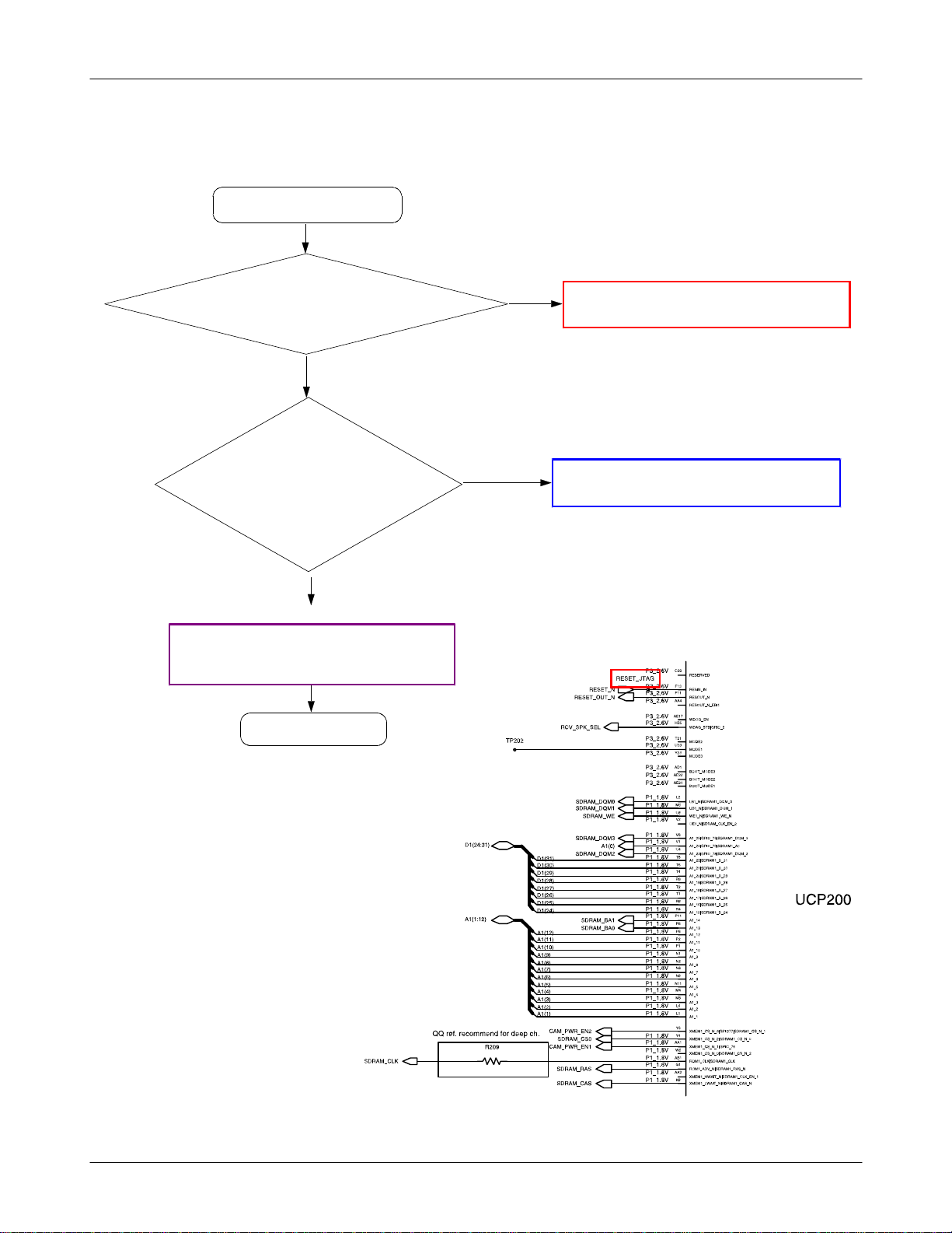
9-2. Initial
Flow Chart of Troubleshooting
Initial Failure
Yes
RESET_JTAG ="H"?
Yes
IS [TA_A200, TP_RAS,
TP_CAS,TP209,TP_NAN
D_CE, TP_ALE, TP210,
TP_SDRAM_CE]
OK?
OK?
Yes
Check the circuit around LCD & HDC400
(Short or not solder)
Yes
END
No
Check the circuit connected to reset
No
Check the circuit related to UME200
9-4
SAMSUNG Proprietary-Contents may change without notice
This Document can not be used without Samsung's authorization

Flow Chart of Troubleshooting
9-5
SAMSUNG Proprietary-Contents may change without notice
This Document can not be used without Samsung's authorization
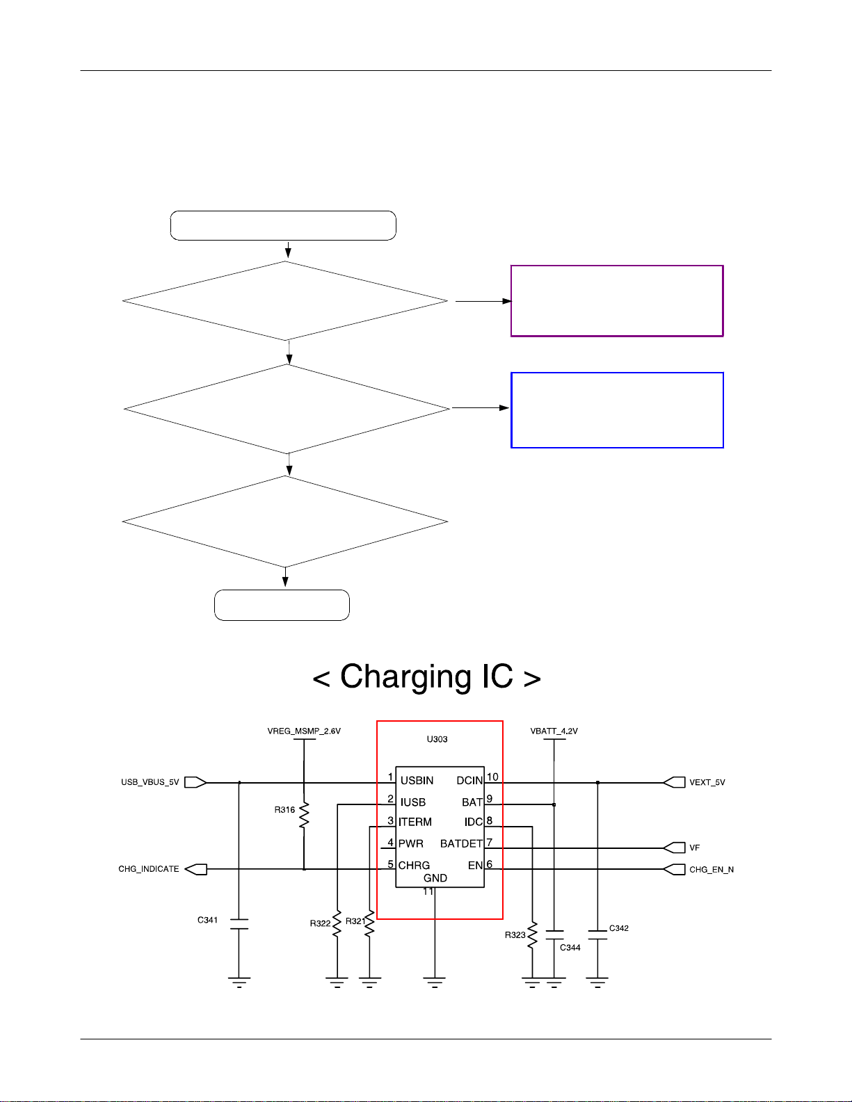
9-3. Charging Part
Abnormal charging part
Flow Chart of Troubleshooting
Yes
C410=5V?
Yes
U303 pin5 = "H"?
Yes
Check the Battery & TA
Yes
END
No
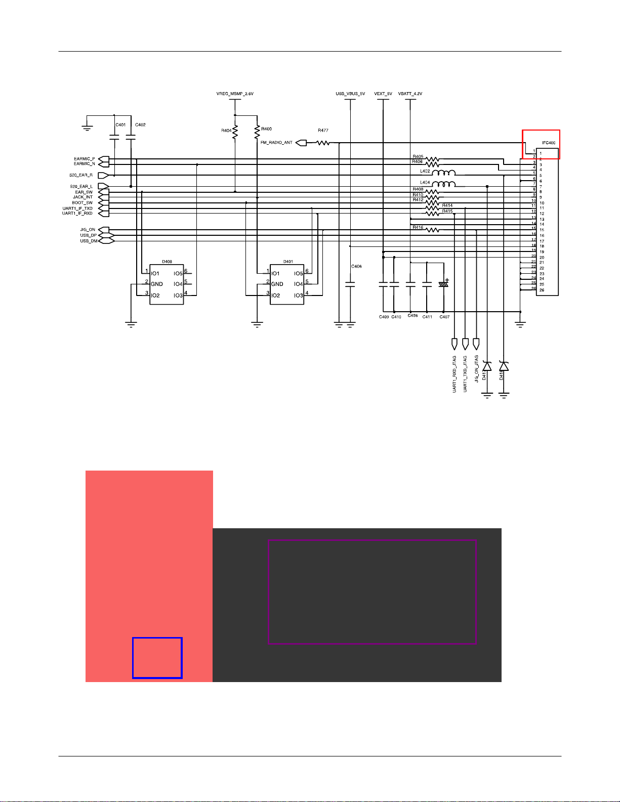
Resolder IFC400
No
Replace U303
9-6
SAMSUNG Proprietary-Contents may change without notice
This Document can not be used without Samsung's authorization
Flow Chart of Troubleshooting
9-7
SAMSUNG Proprietary-Contents may change without notice
This Document can not be used without Samsung's authorization
Flow Chart of Troubleshooting
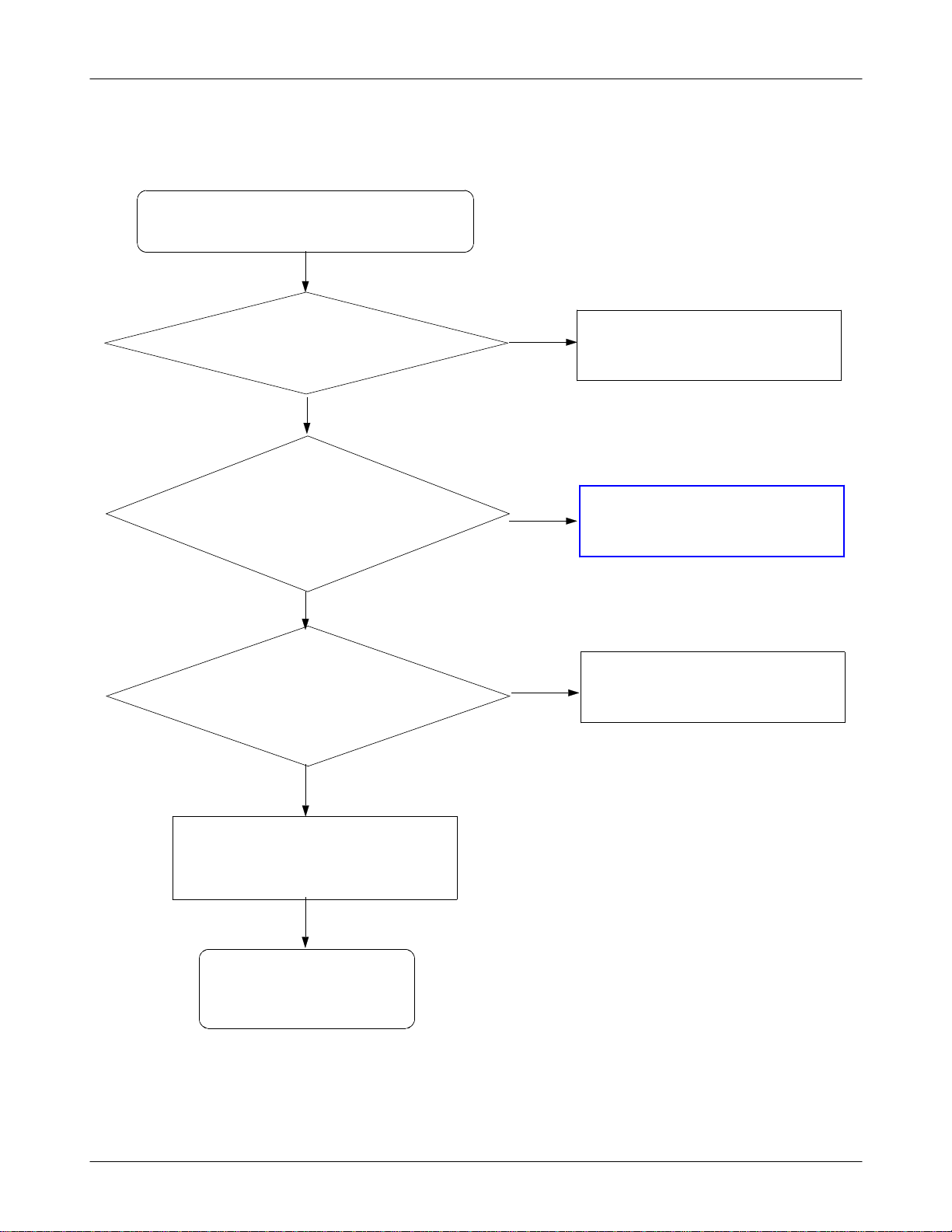
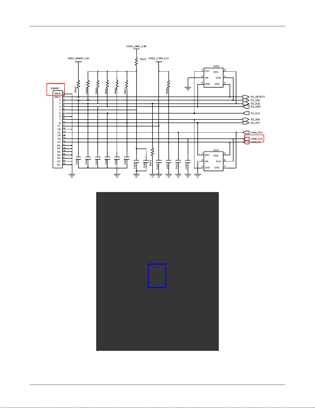
9-4. Sim Part
Phone can't access SIM Card
Yes
C445="H"?
Yes
No
Check the SIM POWER
After Power ON,
Check USIM_CLK Signal on
pin15ofSIM400inafew
After SIM card insert,
second
Yes
pin 13 of SIM400 =
"H(USIM_RST)"?
Yes
Check the SIM Card
Yes
No
Check the 32.768 kHz OSC300
No
Replace PBA
END
9-8
SAMSUNG Proprietary-Contents may change without notice
This Document can not be used without Samsung's authorization
Flow Chart of Troubleshooting
9-9
SAMSUNG Proprietary-Contents may change without notice
This Document can not be used without Samsung's authorization
Flow Chart of Troubleshooting
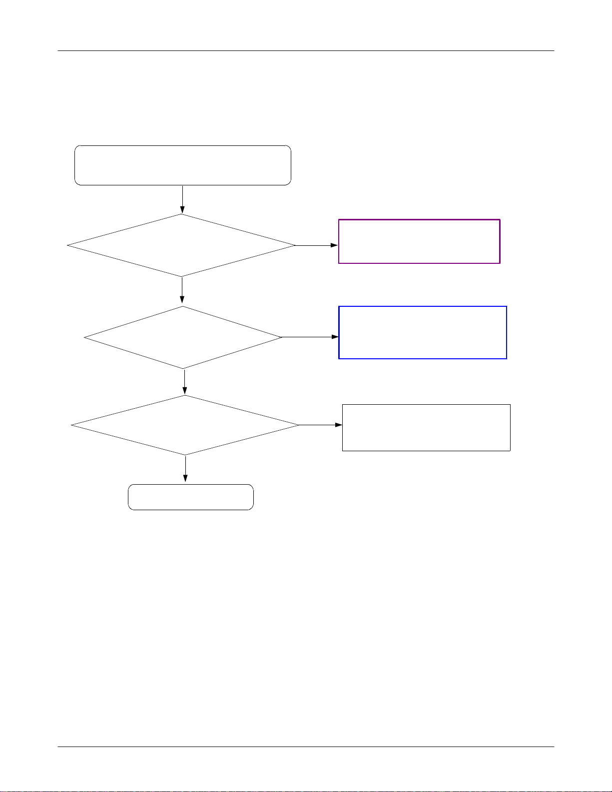
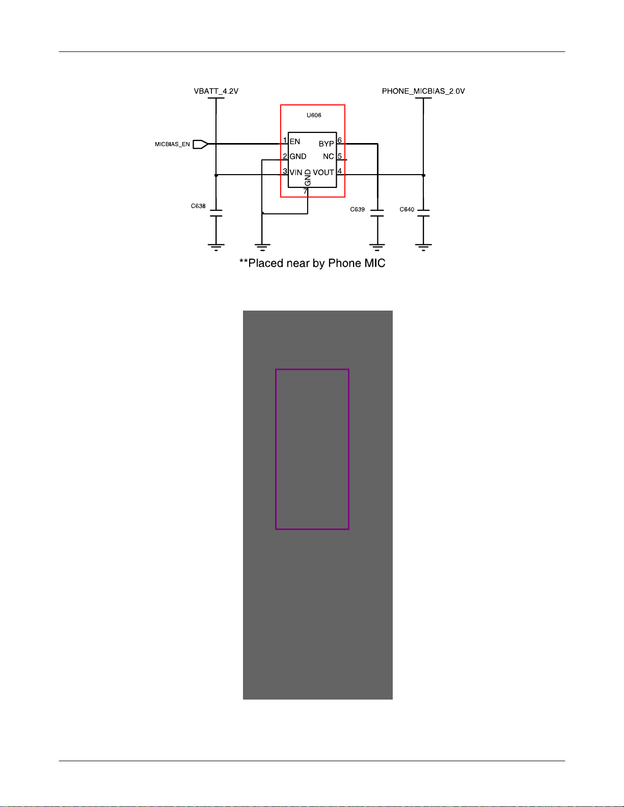
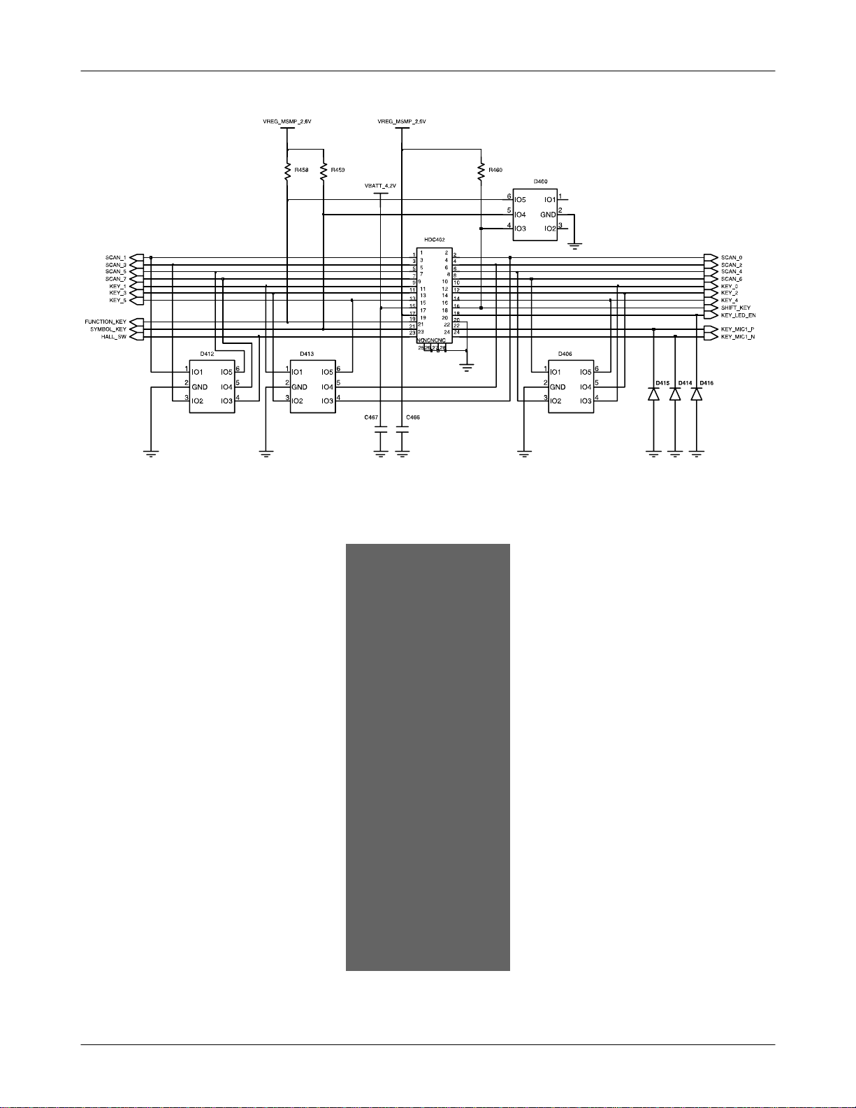
9-5. Microphone Part
Microphone does not work
Yes
Check the connection
HDC402 ok?
Yes
C640 is 2.0V
Yes
Is microphone ok?
Yes
END
No
No
No
Assemble the connector tightly.
Resolder or change U606
Change the Key PBA
9-10
SAMSUNG Proprietary-Contents may change without notice
This Document can not be used without Samsung's authorization
Flow Chart of Troubleshooting
9-11
SAMSUNG Proprietary-Contents may change without notice
This Document can not be used without Samsung's authorization
Flow Chart of Troubleshooting
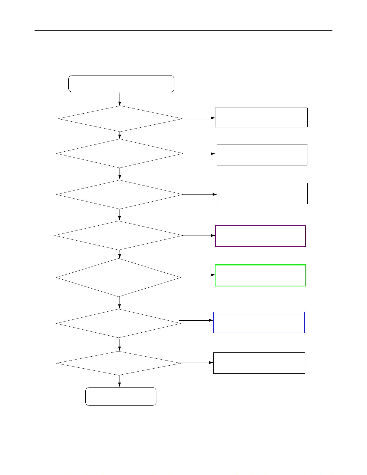
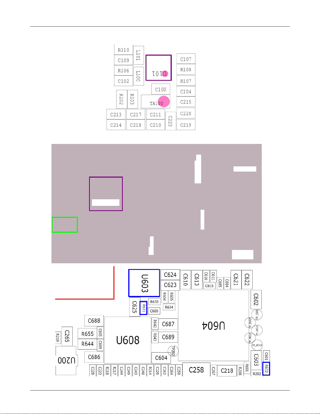
9-6. Speaker Part(Melody)
Speaker does not work
Is the terminal of speaker
OK?
Yes
No
Check the Speaker Wire
Yes
Check the
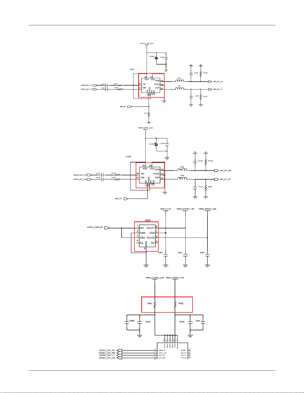
AMP_OUT_LM/LP/RM/RP
ChecktheEarjackFPCB
Check the output circuit
of U101(Sub), U105(Sub)
Is the R112(Sub) 'H' and
R631(Sub), R632(Sub) is
ok?
Yes
ok?
Yes
Yes
CODEC OUT
LM/LP/RM/RP ok?
Yes
'H' ?
No
No
No
No
No
ResolertheSpeakerwire
Change or Resolder Earjack FPCB
Change or Resolder U101(Sub),
U105(Sub)
Check the Slide FPCB
Change or Resolder U603(Sub)
Yes
Is Speaker OK ?
Yes
END
No
Change the Speaker
9-12
SAMSUNG Proprietary-Contents may change without notice
This Document can not be used without Samsung's authorization
Flow Chart of Troubleshooting
9-13
SAMSUNG Proprietary-Contents may change without notice
This Document can not be used without Samsung's authorization
Flow Chart of Troubleshooting
9-14
SAMSUNG Proprietary-Contents may change without notice
This Document can not be used without Samsung's authorization
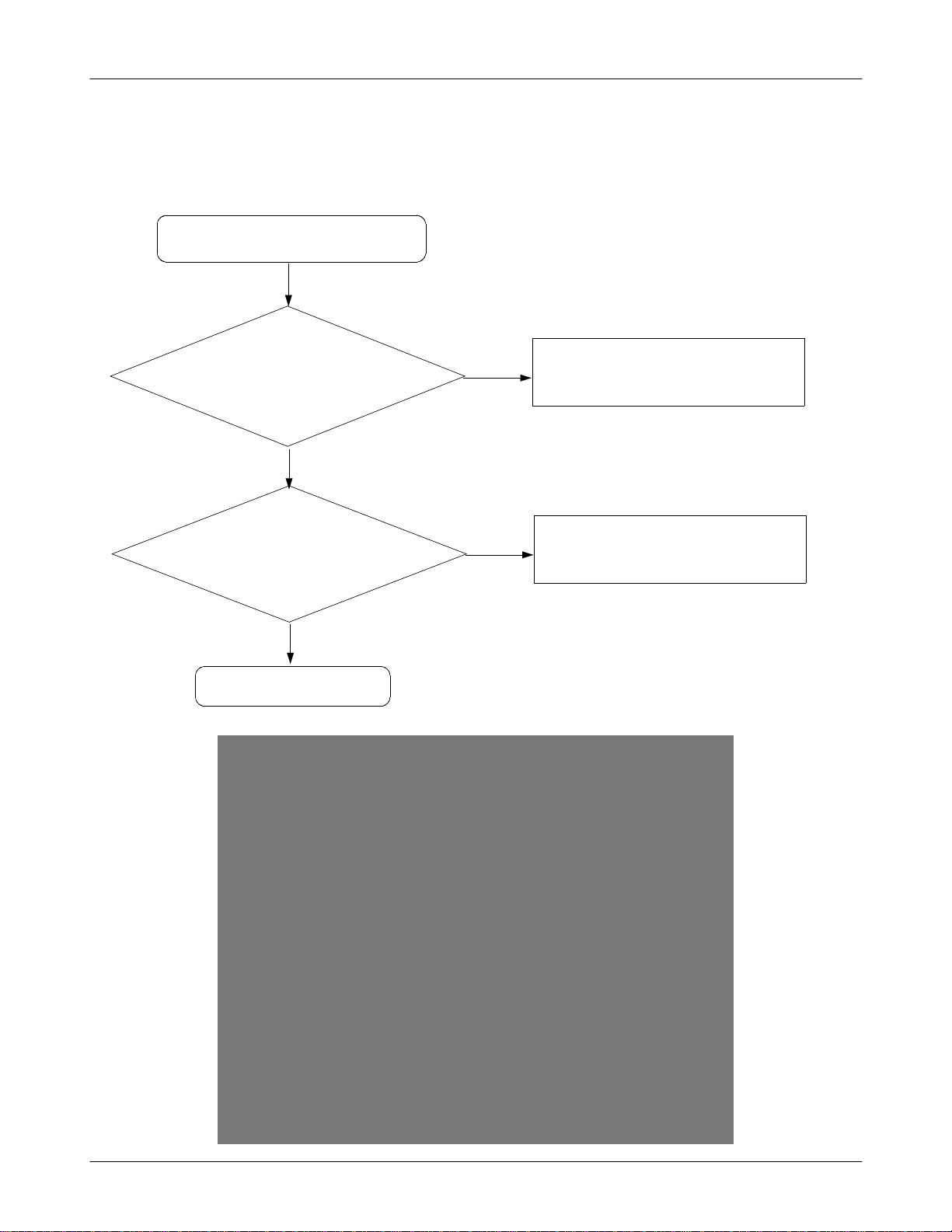
9-7. Key Data Input
Check Initial Operation
Flow Chart of Troubleshooting
Yes
When one of the keys is
pushed,
is it displayed on LCD?
Yes
When one of the keys is
pushed,
KBIO signal is OK?
Yes
END
No
Check the Dome sheet & Key Pad
No
Replace the PBA
9-15
SAMSUNG Proprietary-Contents may change without notice
This Document can not be used without Samsung's authorization
Flow Chart of Troubleshooting
9-16
SAMSUNG Proprietary-Contents may change without notice
This Document can not be used without Samsung's authorization
 Loading...