

GSM TELEPHONE
SGH-F500
GSM TELEPHONE
CONTENTS
Specification
1.
Exploded View and Parts list
2.
Chart of Troubleshooting
3.
Array course control
4.
Block Diagrams
5.
PCB Diagrams
6.
MAIN Electrical Parts List
7.
Reference data
8.
Safety Precautions
9.
Product Function
10.

Specification
1.
GSM General Specification
1-1.
GSM TX power class
1-2.
Exploded View and Parts list
2.
Cellular phone Exploded View
2-1.
Cellular phone Parts list
2-2.
Disassembly
2-3.
Assembly
2-4.
ChartofTroubleshooting
3.
Baseband
3-1.
...............................................................................................................2-9
..................................................................................................................2-11
............................................................................................................3-1
Contents
.......................................................................................1-1
...............................................................................................1-2
..................................................................................2-1
............................................................................................2-2
3-1-1.
3-1-2.
3-1-3.
3-1-4.
3-1-5.
3-1-6.
3-1-7.
3-1-8.
3-2.
3-2-1.
3-2-2.
3-2-3.
3-2-4.
3-2-4.
3-2-6.
Power ON
System Initial
SIM Part
Charging Part
Microphone Part
Speaker Part
Camera Part
LCD
.............................................................................................................3-21
RF
......................................................................................................................3-13
EGSM
DCS
PCS
EGSM
DCS
BLUETOOTH
Rx ......................................................................................................3-24
Rx ......................................................................................................3-25
&
.....................................................................................................3-1
................................................................................................3-5
.......................................................................................................3-8
.............................................................................................3-10
.........................................................................................3-12
..............................................................................................3-15
..............................................................................................3-18
Rx ...................................................................................................3-23
Tx ...................................................................................................3-27
PCS
Tx .........................................................................................3-28
..............................................................................................3-30

Array course control
4.
Downloading Binary Files
4-1.
Pre-requsite for Downloading
4-2.
S/W Downloader Program
4-3.
Block Diagrams
5.
PCB Diagrams
6.
MAIN Electrical Parts List
7.
Reference data
8.
Reference Abbreviate
8-1.
Contents
......................................................................................4-2
................................................................................4-2
.....................................................................................4-3
..............................................................................................8-1
Safety Precautions
9.
Repair Precaution
9-1.
ESD(Electrostaically Sensitive Devices) Precaution
9-2.
Product Function
10.
......................................................................................................9-1
................................................9-2
1. Specification
1-1. GSM/WCDMA General Specification
EGSM 900
Phase 2
Freq. Band[MHz]
Uplink/Downlink
ARFCN range
Tx/Rx spacing 45 MHz 95 MHz 80 MHz 190 MHz
Mod. Bit rate/
Bit Period
Time Slot
Period/Frame
Period
Modulation 0.3 GMSK 0.3 GMSK 0.3 GMSK
880~915
925~960
0~124 &
975~1023
270.833 kbps
3.692 us
576.9 us
4.615 ms
DCS1800
Phase 1
1710~1785
1805~1880
512~885 512~810 10562~10838
270.833 kbps
3.692 us
576.9 us
4.615 ms
PCS1900 WCDMA
1850~1910
1930~1990
270.833 kbps
3.692 us
576.9 us
4.615 ms
1920~1980
2110~2170
3.84 Mcps/s
10 ms
UL:2BPSK
DL:QPSK
MS Power 33dBm~5dBm 30dBm~0dBm 30dBm~0dBm
Power Class 5 pcl ~ 19 pcl 0 pcl ~ 15 pcl 0 pcl ~ 15 pcl CLASS3
Sensitivity -102 dBm -100 dBm -100 dBm -106.7 dBm
TDMA Mux 8 8 8 -
Cell Radius 35 Km 2 Km - -
MAX:24(+1,-3) dBm
MIN:<-50 dBm
1-1
SAMSUNG Proprietary-Contents may change without notice
This Document can not be used without Samsung's authorization
Specification
1-2. GSM TX power class
TX Power
control level
EGSM900
533±2dBm
631±2dBm
729±2dBm
827±2dBm
925±2dBm
10 23±2 dBm
11 21±2 dBm
TX Power
DCS1800
control level
030±3dBm
128±3dBm
226±3dBm
324±3dBm
422±3dBm
520±3dBm
618±3dBm
TX Power
control level
PCS1900
030±3dBm
128±3dBm
226±3dBm
324±3dBm
422±3dBm
520±3dBm
618±3dBm
12 19±2 dBm
13 17±2 dBm
14 15±2 dBm
15 13±2 dBm
16 11±3 dBm
17 9± 3dBm
18 7±3 dBm
19 5±3 dBm
716±3dBm
814±3dBm
912±4dBm
10 10±4 dBm
11 8±4 dBm
12 6±4 dBm
13 4±4 dBm
14 2±5 dBm
716±3dBm
814±3dBm
912±4dBm
10 10±4 dBm
11 8±4 dBm
12 6±4 dBm
13 4±4 dBm
14 2±5 dBm
15 0±5 dBm
1-2
15 0±5 dBm
SAMSUNG Proprietary-Contents may change without notice
This Document can not be used without Samsung's authorization
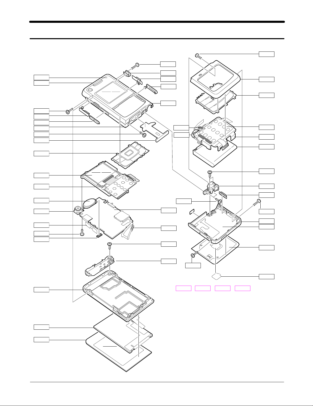
Exploded View and Parts List
2.
Cellular phone Exploded View
2-1.
QCR05
QCR67
QWD01
QRF01
QCR67
QRF03
QVO01
QBR19
QCR03
QMC01
QKP02
QLC01
QBR02
QSP01
QCA01
QVK01
QCR12
QAN05
QRF01
QCK02
QKP01QKP01QSD01
QBR18
QMP01
QME16
QCR12
QMI03
QMO01
QCR05
QHI15
QKP01
QME01
QBR17
QBA01
QCR12
QHI01
QCK01
QCR03
QHI17
QFL01
QKP03
QRE01
QLC02
QMW01
QAN02
QCR03
QHI16 QHI01
QFL01
2-1
SAMSUNG Proprietary-Contents may change without notice
This Document can not be used without Samsung's authorization
+
QCK03
QCR12=+

Main Electrical Parts List
Cellular phone Parts list
2-2.
Design LOC Discription SEC CODE
QAN02
QAN05
QBA00
QBA01
QBR02
QBR17
QCA01
QCK03
QCR03
QCR03
QCR05
QCR05
QCR12
QCR67
QHI15
QKP01
QKP02
QKP03
QLC01
QLC02
QMC01
QME01
QME16
QMI03
QMO01
QMP01
QMW01
QRE01
QRF01
QSP01
QVK01
QWD01
QFR01
QHI16
QHI17
QBR18
QBR19
ASSY MEC-RUBBER ANT CON GH75-09161A
COVER BATTERY PACK-950MAH,BLK, GH43-02844A
INNER BATTERY PACK-880MAH,BLK, GH43-02588A
NDC-CASE SWING UPPER V2 GH71-07017A
ASSY KEYPAD-MAIN(OPEN/BLK) GH98-02861A
ASSY KEYPAD-SUB(OPEN/BLK) GH98-02860A
QSD01 PMO-COVER MICRO SD GH72-35529A
QCR12 SCREW-MACHINE
QFL01 ASSY CASE-SWING LOWER GH98-02337A
QHI01 ASSY HINGE GH98-03747A
QCK01 PMO-CAMERA KEY GH72-33543A
QCK02 PMO-HOLD KEY GH72-35531A
QRF03 PMO-EAR JACK COVER GH72-35534A
QVO01 PMO-VOLUME KEY GH72-33544A
INTENNA-SGHF500 GH42-01094A
ASSY BRACKET-SUB GH98-03560A
ASSY BRACKET-BATT GH98-02339A
UNIT-PHONE CAMERA GH59-03593A
PMO-KEY TOUCH OK GH72-35526A
SCREW-MACHINE
SCREW-MACHINE
SCREW-MACHINE
SCREW-MACHINE
SCREW-MACHINE
SCREW-MACHINE
MEA-TOUCH KEYPAD KIT GH97-07638A
LCD-SGHF500 GH07-01032A
LCD-MODULE SGHF500 GH07-00992A
PMO-SIM COVER GH72-35542A
UNIT-TF KEY PBA GH59-03767A
UNIT-CON TO CON FPCB GH59-03792A
ASSY RUBBER-MIC HOLDER GH98-03682A
MOTOR DC-SPHB6400 GH31-00271A
PBA MAIN-SGHF500 GH92-03070A
ASSY COVER-WINDOW MAIN GH98-02870A
ASSY COVER-REAR GH98-02868A
PMO-COVER RF V2 GH72-35129A
SPEAKER
UNIT-SIDE KEY GH59-03762A
ASSY COVER-WINDOW SUB GH98-02869A
ASSY COVER-FRONT GH98-02863A
ASSY COVER-SWING LOWER GH98-05068A
ASSY COVER-SWING BELT GH98-05119A
ASSY COVER-MAIN BELT
ASSY COVER-MAIN BELT
R
L
GH98-02864A
GH98-02865A
6001-001811
6001-001811
6001-001478
6001-001478
6001-001530
6001-002083
3001-002109
6001-001530
2-2
SAMSUNG Proprietary-Contents may change without notice
This Document can not be used without Samsung's authorization
Main Electrical Parts List
Discription SEC CODE
IC-MEMORY CARD
CONNECTOR-ADAPTOR
BAG PE
BAG ZIPPER
1109-001363
3719-001319
6902-000634
6902-000683
CBF INTERFACE-AV CABLE GH39-00442A
CBF INTERFACE-DLC,X830,BLK,PCB GH39-00720A
ADAPTOR-SGHE690,BLK,EU,A_TYPE GH44-01361A
S/W CD-SAMSUNG PC STUDIO
3.1,F
GH46-00392A
UNIT-EARPHONE,SGHE790,MAIN,A-T GH59-03884A
LABEL(P)-IMEI GH68-01335D
LABEL(R)-WATER SOAK GH68-09361A
MANUAL USERS-EU DUTCH GH68-13752A
MANUAL USERS-EU ENGLISH GH68-13753A
LABEL(R)-MAIN EU GH68-13981A
BOX(P)-UNIT MAIN EU GH69-05089A
CUSHION-CASE TA2 MA1~2 GH69-05090A
MPR-VINYL BOHO SIM CARD GH74-30419A
TAPE GASK GH74-31723A
MPR-GASK TAPE GH74-31724A
MPR-INSU TAPE GH74-31725A
TAPE-RF CONNECTOR GH74-31726A
TAPE-IF CONNECTOR GH74-31727A
VINYL-BOHO MAIN KEY GH74-32568A
VINYL-BOHO SUB KEY GH74-32569A
TAPE INSU-BOARD GH74-32936A
2-3
SAMSUNG Proprietary-Contents may change without notice
This Document can not be used without Samsung's authorization
Main Electrical Parts List
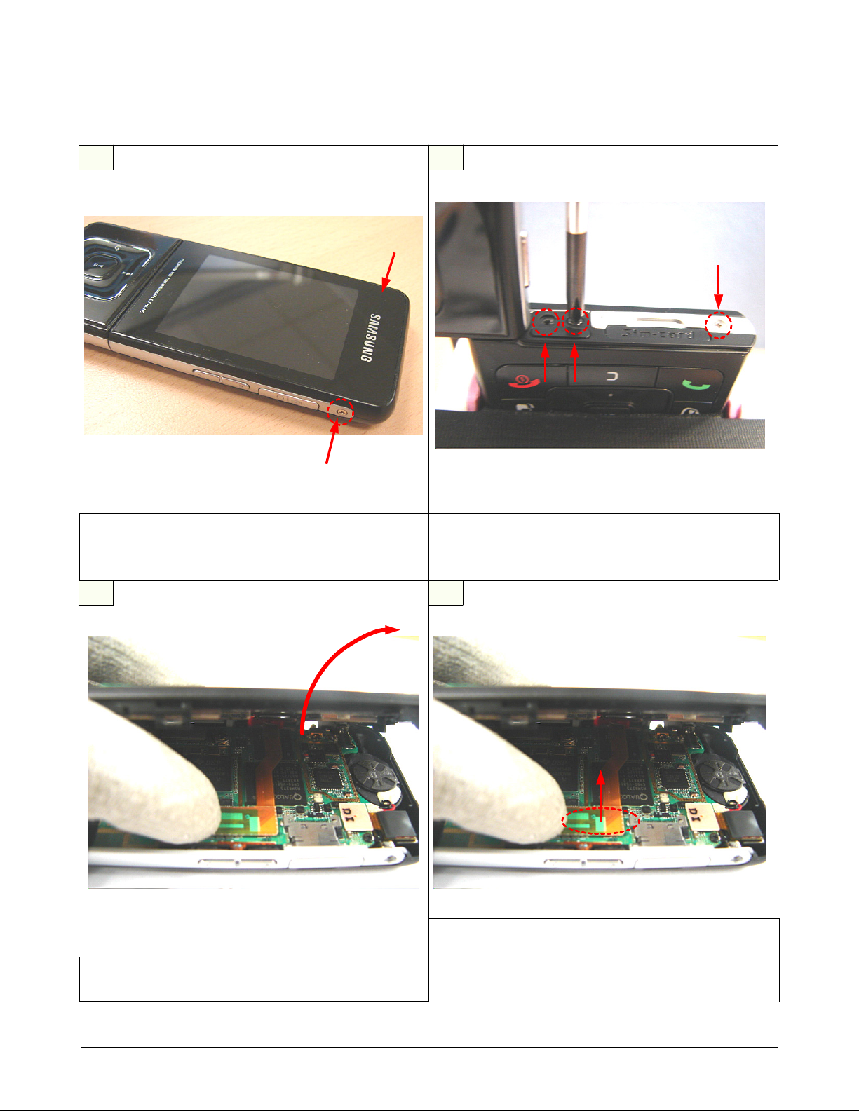
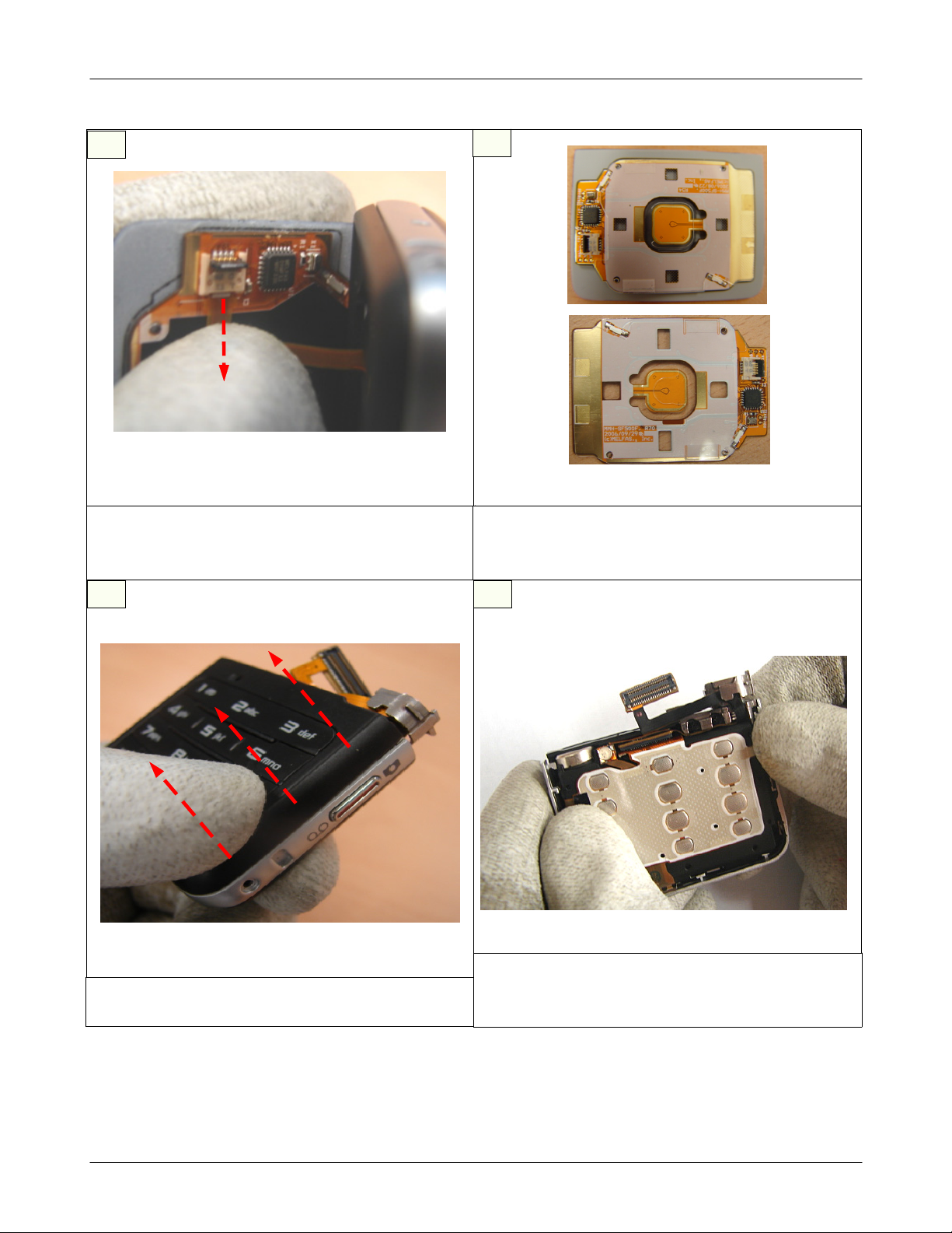
Disassembly
2-3.
1
SCREW REMOVE
1)
Remove the 2POINT SCREWS on the both sides of
SET (SILVER 2 POINT)
1
2
SCREW REMOVE
1)
Remove the 3POINT SCREWS on the upper of SWING
part. (BLACK 2 POINT, SILVER 1 POINT)
2
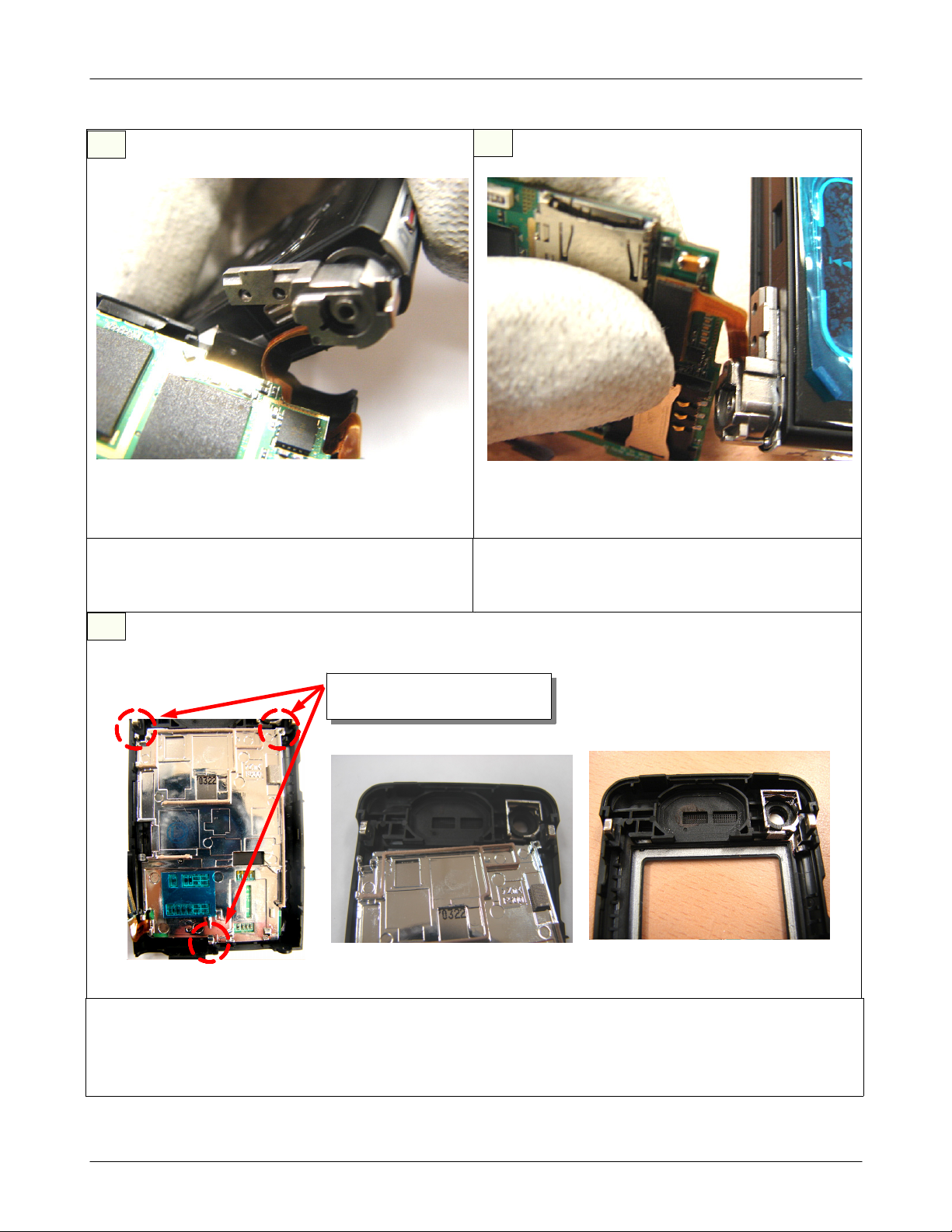
3
DISASSEMBLE REAR ASS'Y
1)
Disassemble REAR ASS'Y from the SET by using tools.
4
1) 2.4"
Disassemble
※
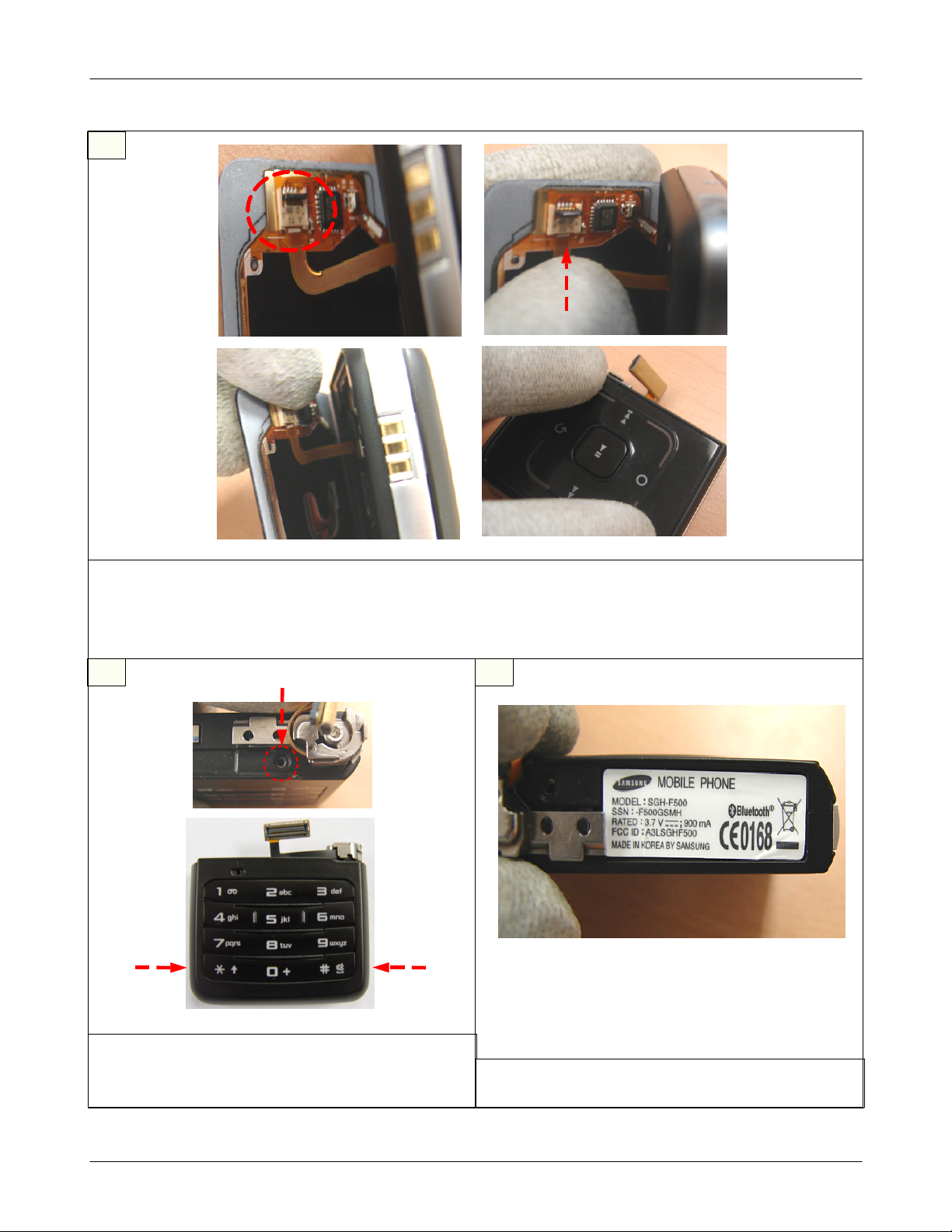
1)
LCD CONNECTOR REMOVE
LCD CONNECTOR from PBA.
2.4"
caution
NO DAMAGE to F-PCB
2-4
SAMSUNG Proprietary-Contents may change without notice
This Document can not be used without Samsung's authorization
Main Electrical Parts List
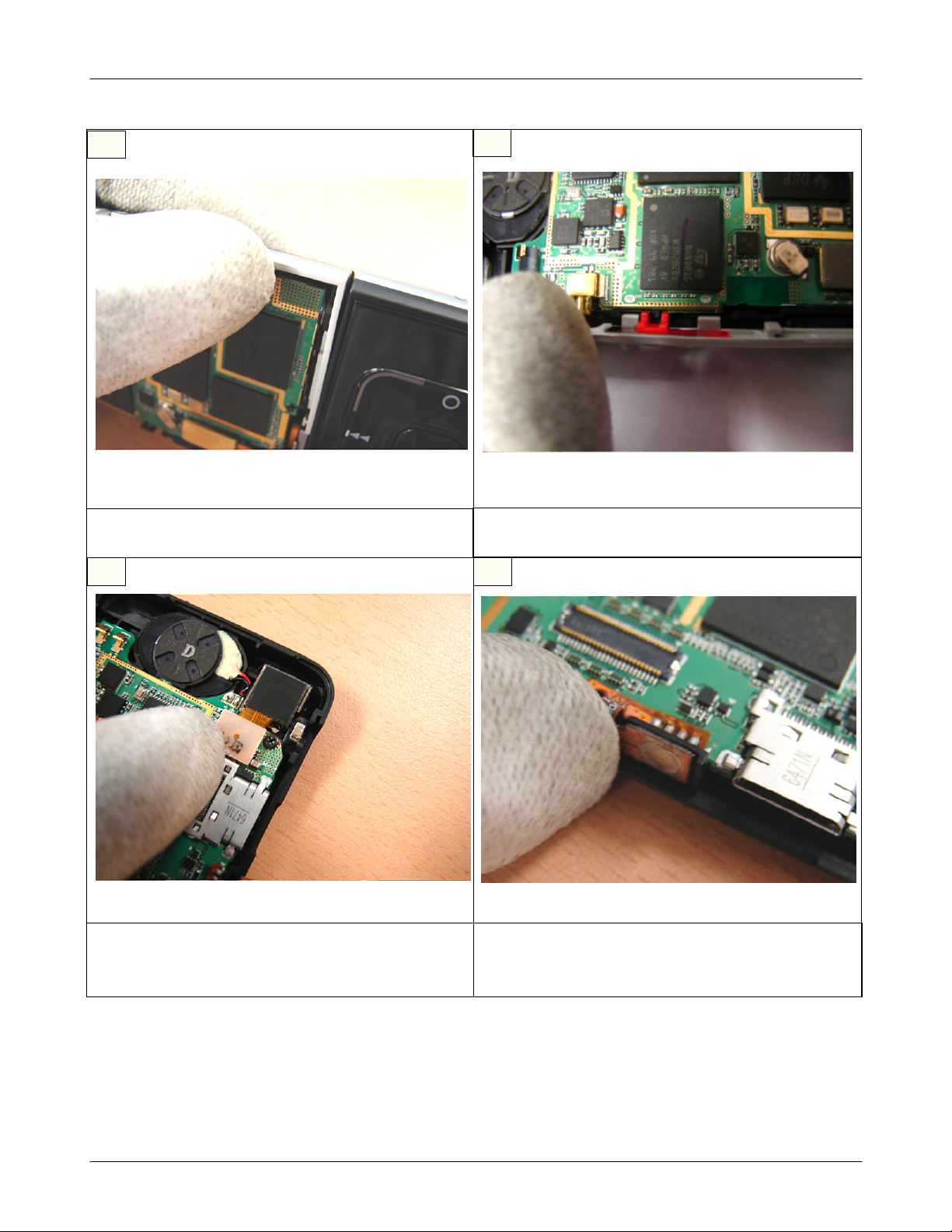
5
REMOVE THE RIGHT SIDE BELT
1)
Remove the SIDE BELT on the right of SET.
7 8
6
REMOVE THE LEFT SIDE BELT
1)
Remove the SIDE BELT on the left of SET.
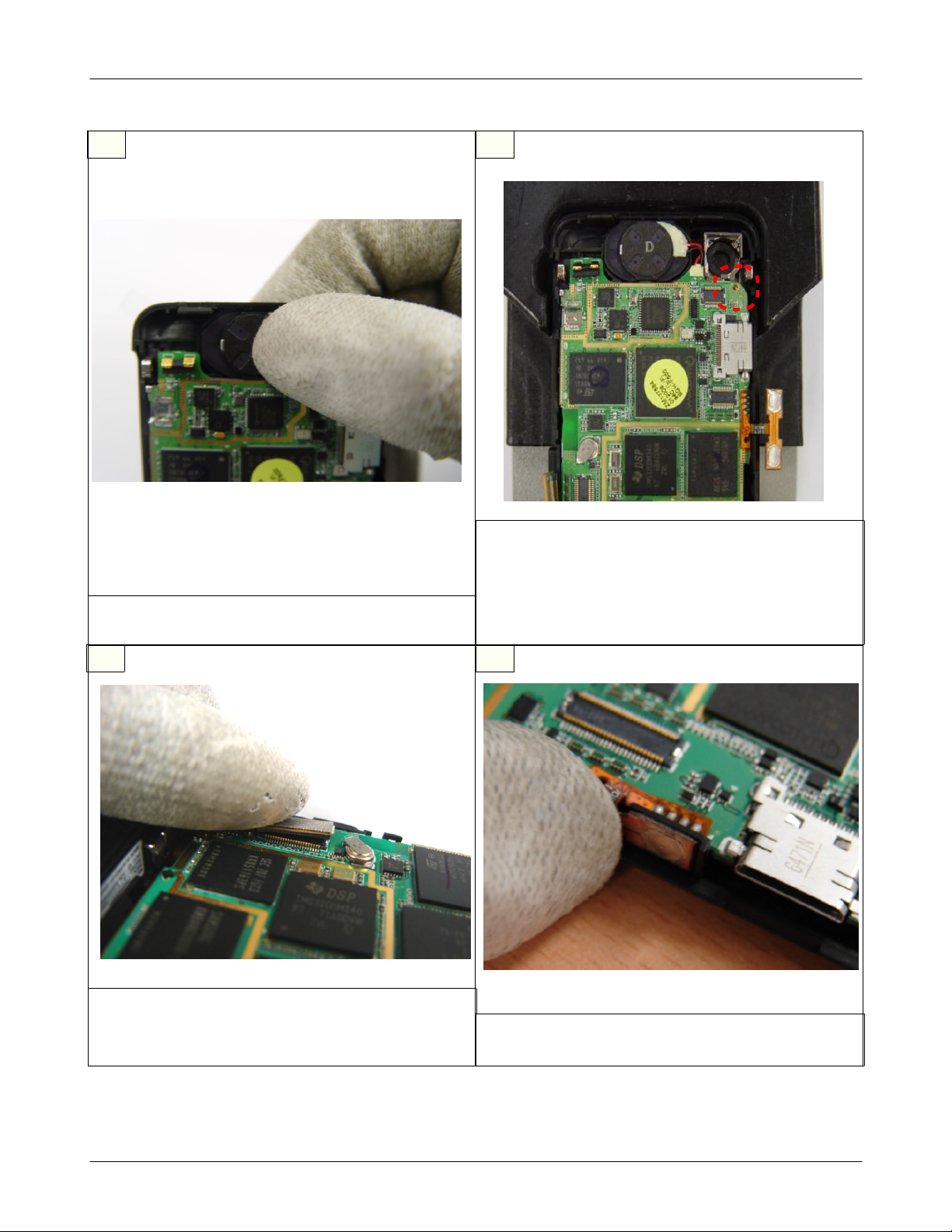
DISASSEMBLE2MEGA CAMERA
1)
Disassemble the2MEGA CAMERA combined with
PBA
SAMSUNG Proprietary-Contents may change without notice
This Document can not be used without Samsung's authorization
DISASSEMBLE VOLUME KEY
1)
Disassemble the VOLUME KEY F-PCB from the
BODY.
2-5
Main Electrical Parts List
9
DISASSEMBLE SUB LCD CONNECTOR
1)
Disassemble the SUB LCD CONNECTOR from the
PBA.
10
REMOVE SCREW
1)
Remove the SCREW on the PBA.
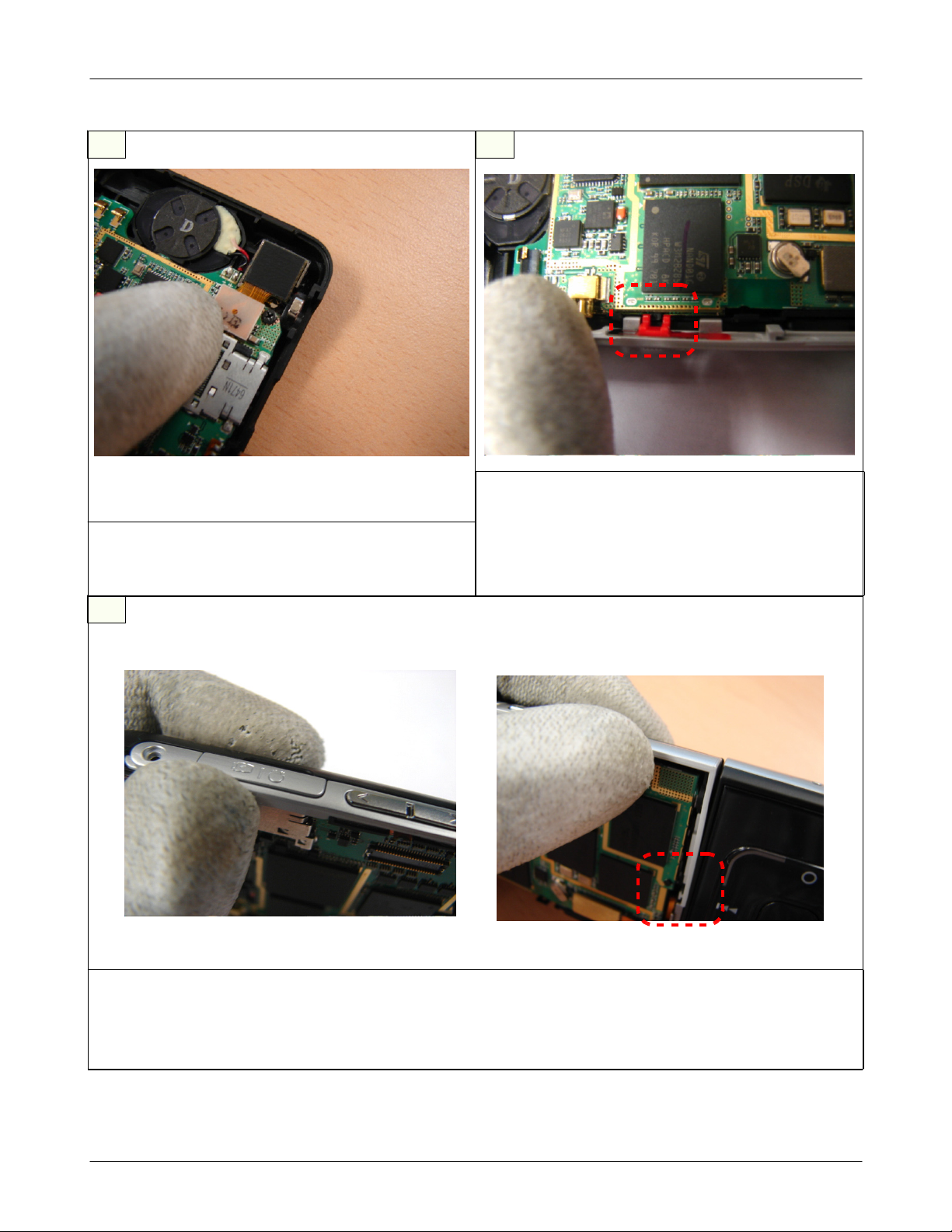
11 12
DISASSEMBLE SPEAKER
1)
Disassemble the SPEAKER from the FRONT
COVER.
1)
Disassemble the PBA ASS'Y from the FRONT
COVER.
DISASSEMBLE PBA ASS'Y
2-6
SAMSUNG Proprietary-Contents may change without notice
This Document can not be used without Samsung's authorization
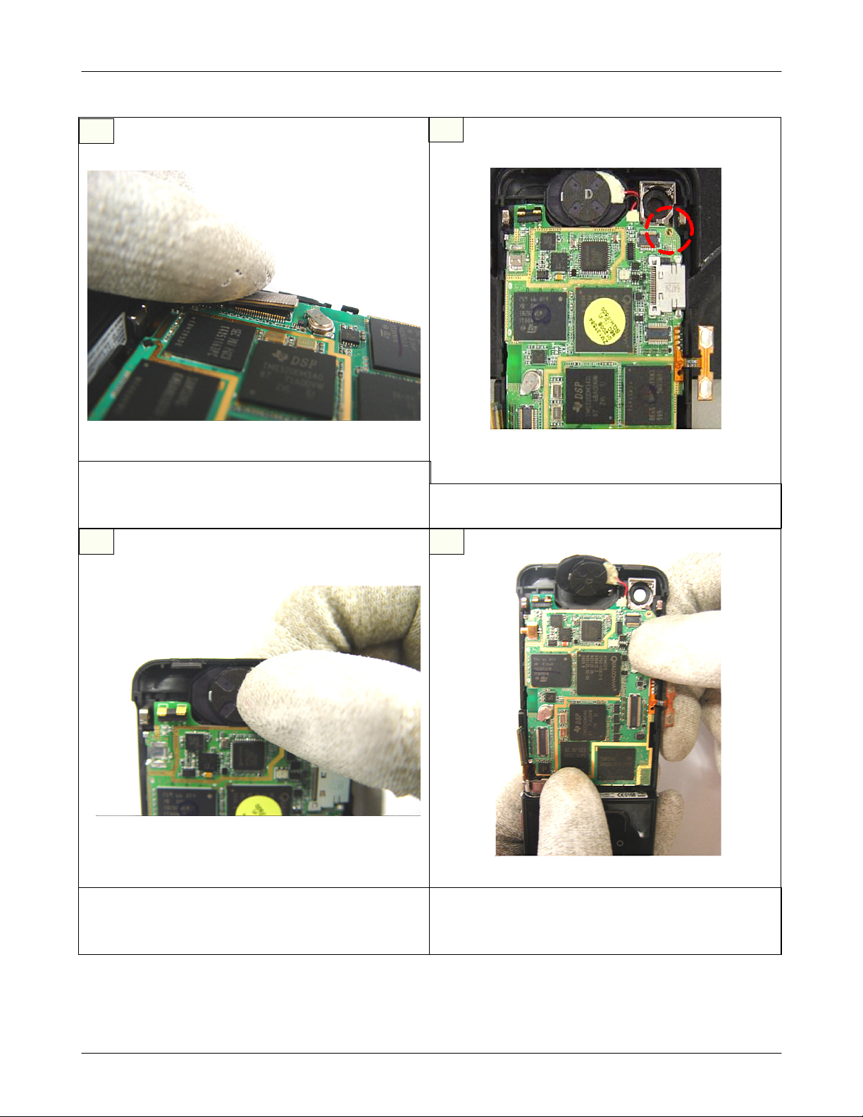
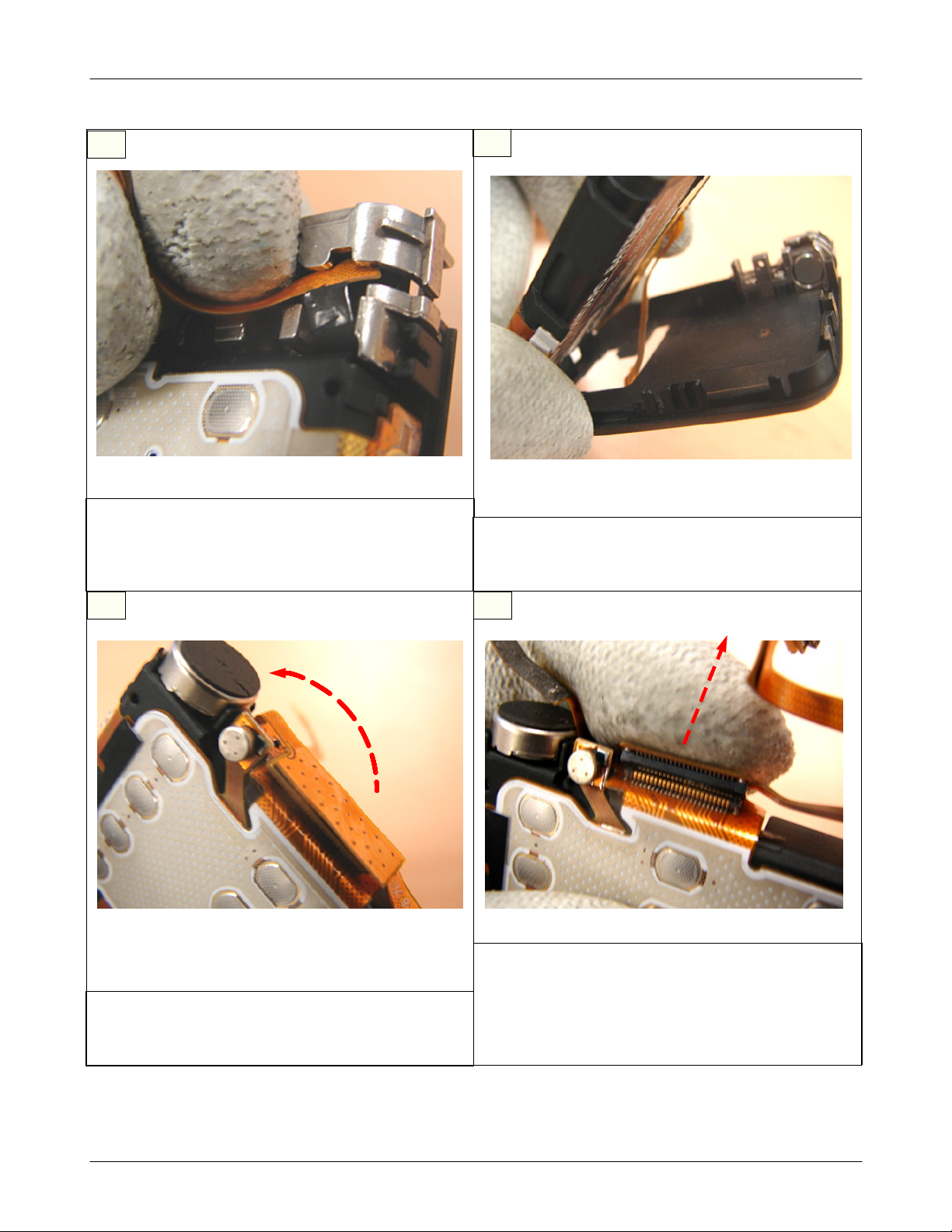
Main Electrical Parts List
13
DISASSEMBLE SWING ASS'Y
1)
Disassemble the HINGE of the SWING ASS'Y from
the REAR part.
14
DISASSEMBLE CON TO CON F-PCB
1)
Disassemble the CON TO CON F-PCB combined
with PBA.
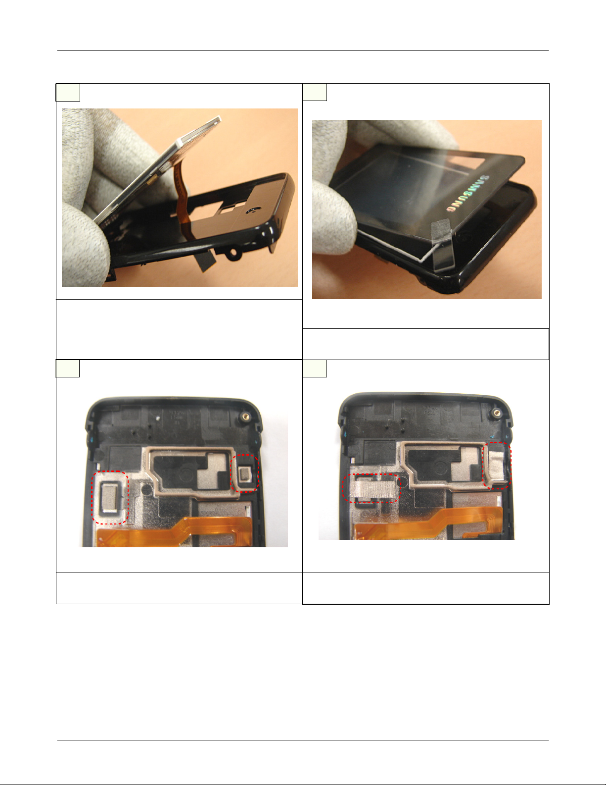
15
Check the Hooks When
Disassemble (3 points)
DISASSEMBLE SHIELD COVER
1)
Disassemble the SHEILD COVER ASS'Y from the FRONT COVER.
caution
※
Remove the SHELID COVER after check the position of the HOOK.
2-7
SAMSUNG Proprietary-Contents may change without notice
This Document can not be used without Samsung's authorization
Main Electrical Parts List
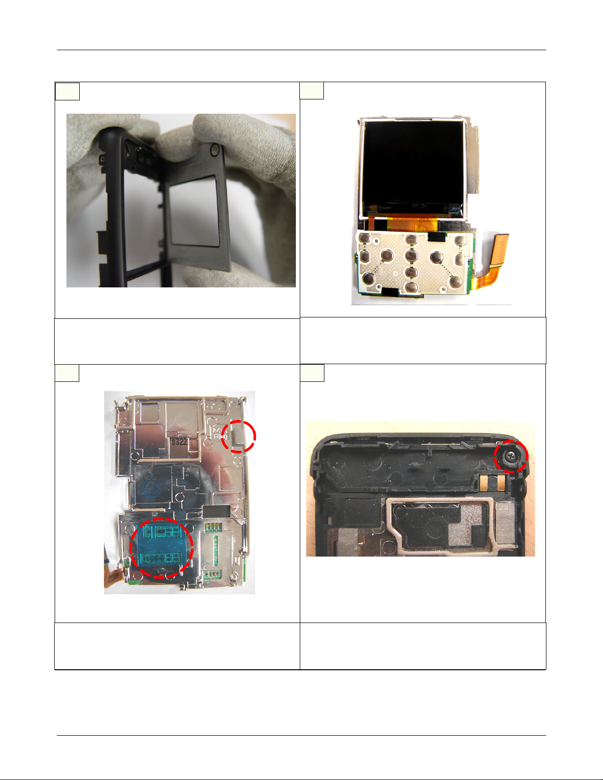
16
REMOVE SUB WINDOW
1)
REMOVE the SUB WINDOW from FRONT COVER
18
17
REMOVE
1)
Remove the
COVER.
19
LCD MODULE
1.5"
LCD MODULE from SHIELD
1.5"
REMOVE SHIELD COVER
1)
Remove subsidiary material 2point combined with SHIELD
COVER
SAMSUNG Proprietary-Contents may change without notice
This Document can not be used without Samsung's authorization
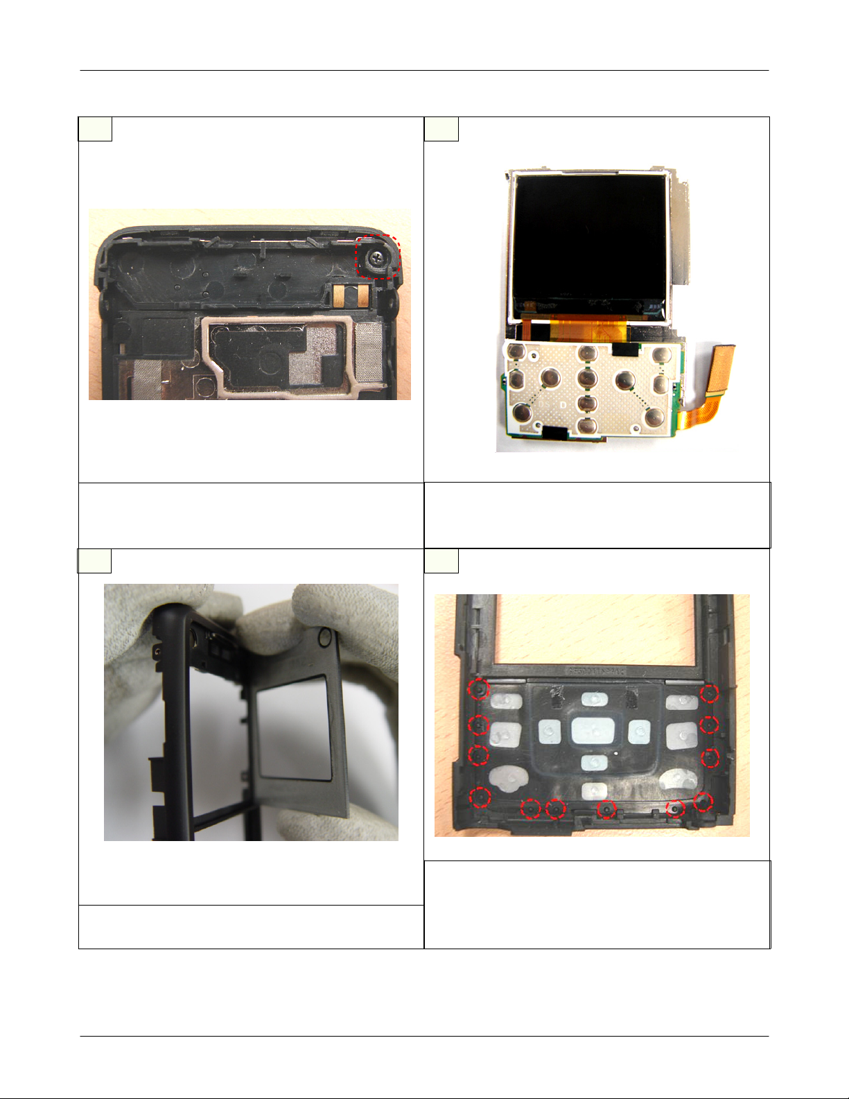
DISASSEMBLEINTENNA
1)
Disassemble INTENNA after remove SCREW
combined with right side of INTENNA
2-8
Main Electrical Parts List
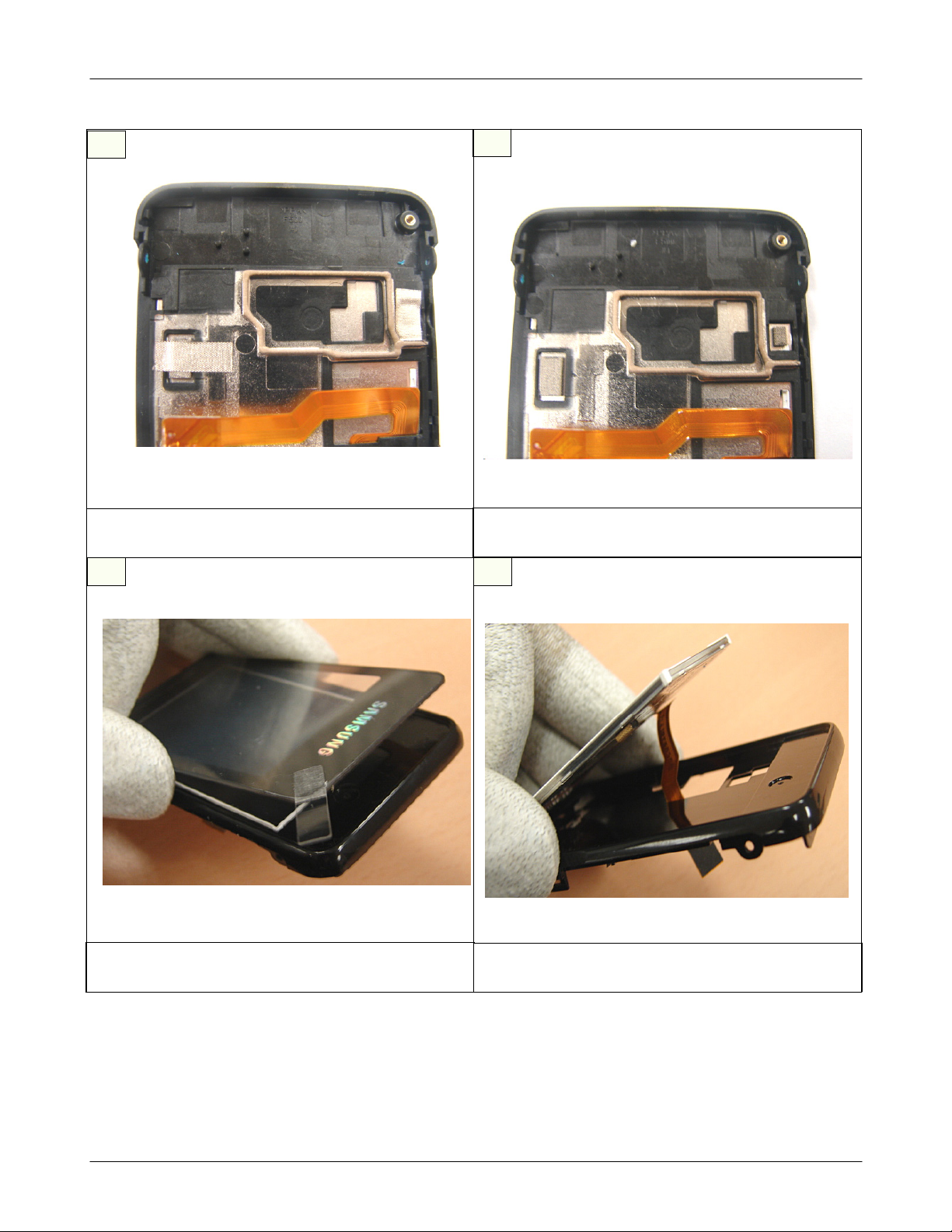
20
REMOVE ELECTRIC CONDUCTION TAPE
1)
Remove TAPE2POINT sticked with
2.4"
LCD
21
1)
Remove sponge2POINT sticked with
22 23
REMOVE ELECTRIC CONDUCTION SPONGE
LCD
2.4"
DISASSEMBLE MAIN WINDOW
1)
Disassemble MAIN WINDOW from REAR ASS'Y
SAMSUNG Proprietary-Contents may change without notice
This Document can not be used without Samsung's authorization
DISASSEMBLE
1)
Disassemble
2-9
LCD
2.4"
LCD MODULE from rear part
2.4"
Main Electrical Parts List
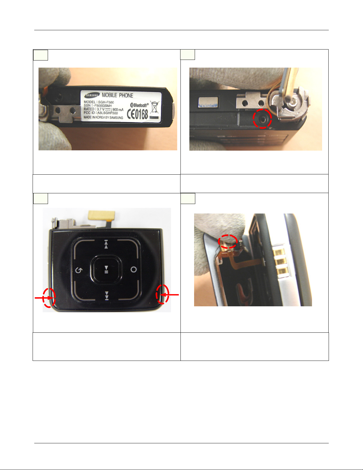
24
REMOVE LABEL
1)
Remove label sticked with upper of SWING ASS'Y
25
1)
Remove SCREW1POINT of SWING ASS'Y
26 27
REMOVE SCREW
1
REMOVE SCREW
1)
Remove SCREW2POINT on both side of SWING
ASS'Y
2
SAMSUNG Proprietary-Contents may change without notice
This Document can not be used without Samsung's authorization
UNCOVER TOUCH KEY CONNECTOR
1)
UNCOVER ACTUATOR OF TOUCH KEY
CONNECTOR
2-10
Main Electrical Parts List
28
DISASSEMBLE TOUCH KEY F-PCB
1)
Disassemble F-PCB combined with TOUCH KEY
CONNECTOR
30
29
REMOVE TOUCH KEY PCB
1)
Remove TOUCH KEY PCB sticked with TOUCH
KEY PAD
31
DISASSEMBLE SWING UPPER
1)
Disassemble SWING UPPER from SWING ASS'Y
SAMSUNG Proprietary-Contents may change without notice
This Document can not be used without Samsung's authorization
DISASSEMBLE SWING SIDE BELT
1)
Disassemble SWING SIDE BELT from SWING
ASS'Y
2-11
Main Electrical Parts List
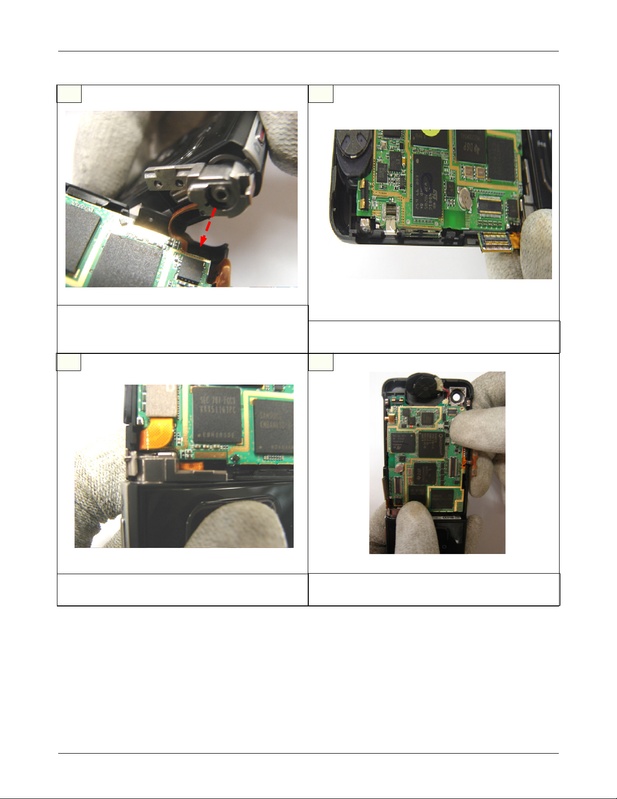
32
DISASSEMBLE CON TO CON F-PCB
1)
Disassemble CON TO CON F-PCB between hinge
caution
※
NO DAMAGE to F-PCB
33
DISASSEMBLE BATTERY BRACKET
1)
Disassemble BATTERY BRACKET from SWING
LOWER
34
DISASSEMBLE ESD F-PCB
1)
Disassemble ESD F-PCB combined with CON TO
CON F-PCB
35
DISASSEMBLE CON TO CON F-PCB
1)
Disassemble CON TO CON F-PCB from
F-PCB.
caution
※
NO DAMAGE to F-PCB
3*4
KEY
2-12
SAMSUNG Proprietary-Contents may change without notice
This Document can not be used without Samsung's authorization
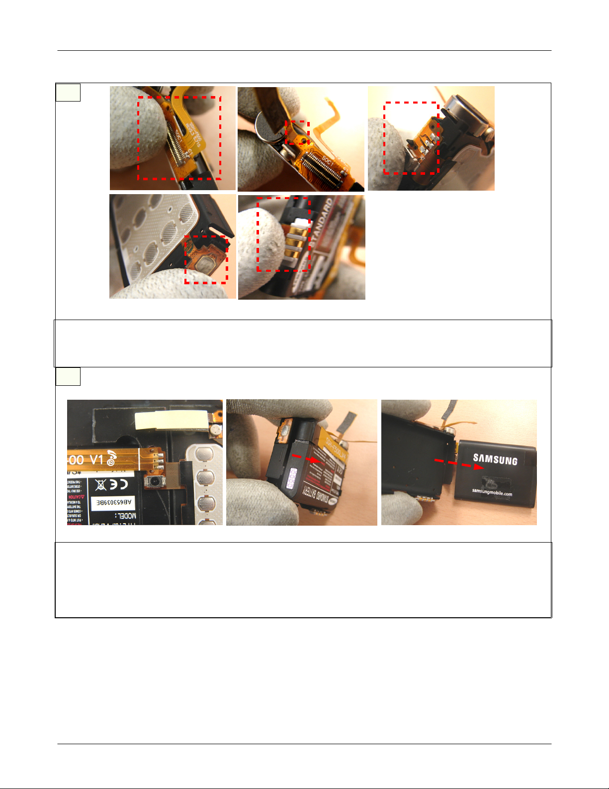
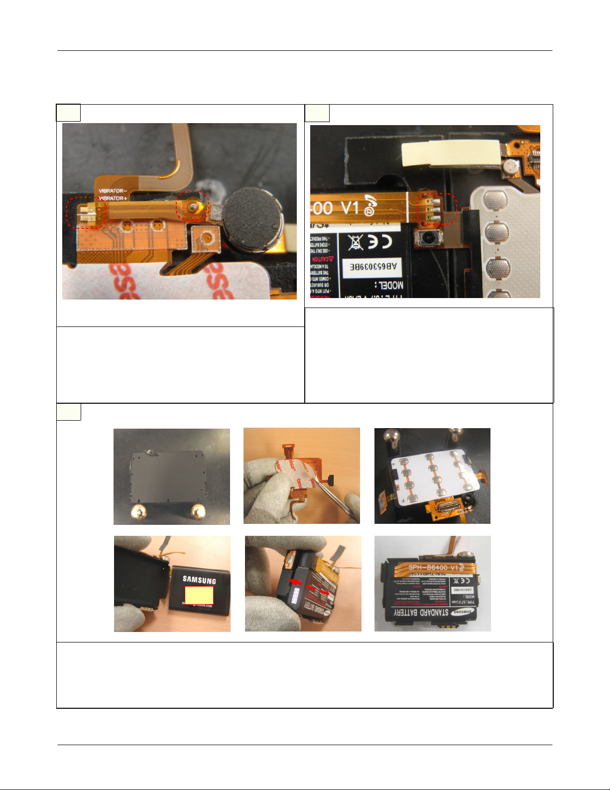
36
Main Electrical Parts List
REMOVE
Remove
MAIN CONNECTOR,BATTERY SOLDERING, CAMERA KEY DOME SHEET, EXT BATTERY CONTACT)
(
3*4
KEY F-PCB
3*4
KEY F-PCB
37
DISASSEMBLE BATTERY
Remove the BATTERY SOLDERING
1.
Disassemble the BATTERY from the BATTERY BRACKET.
2.
caution
※
NO DAMAGE to F-PCB
2-13
SAMSUNG Proprietary-Contents may change without notice
This Document can not be used without Samsung's authorization
Main Electrical Parts List
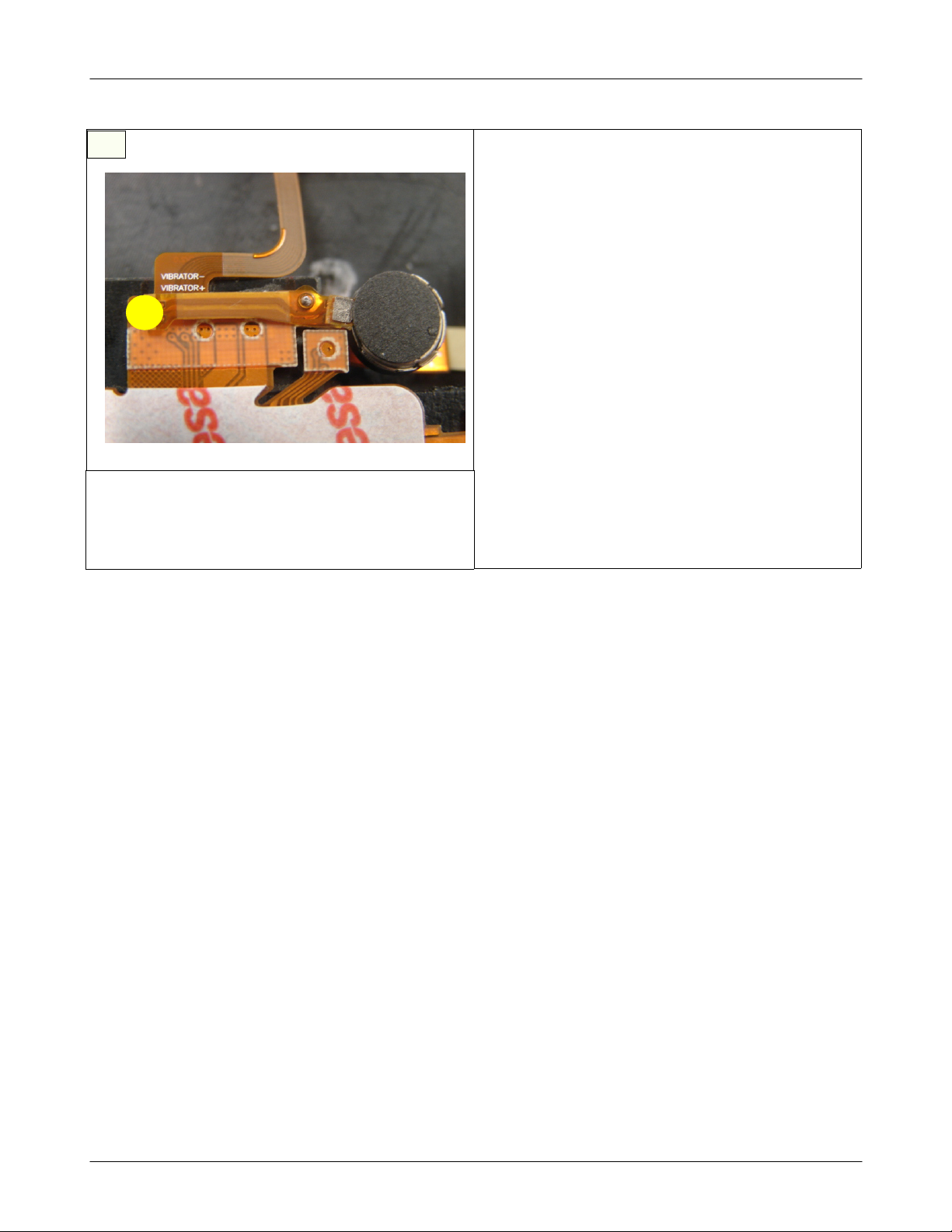
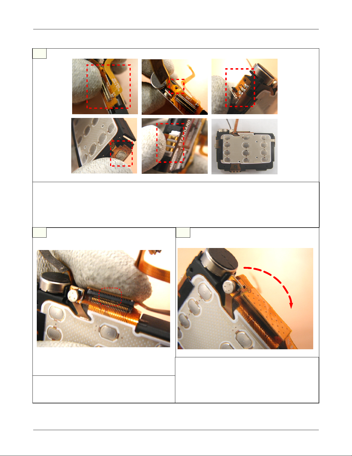
38
REMOVE MOTOR
1)
Disassemble the MOTOR from the
after removing SOLDERING.
Be careful not to damage the CON TO CON
2)
3*4
KEY PCB
.
2-14
SAMSUNG Proprietary-Contents may change without notice
This Document can not be used without Samsung's authorization
2-4.
Main Electrical Parts List
Assembly
1
MOTOR SOLDERING
1)
Solder the MOTOR to the
caution
※
When soldering the MOTOR,
be overlapped with MOTOR PIN's holes.
KEY PCB.
3*4
3*4
KEY's holes must
2
BATTERY SOLDERING
1)
KEY ASS'Y와BATTERY를SOLDERING
3*4
Solder the
caution
※
In the unlikely event of SHORT, It may be difficult
to supply the right power.
KEY ASS'Y to the BATTERY.
3*4
한다
.
3
①
④
ATTACH
Prepare BATTERY BRACKET
1.
Attach the
3.
Combine the BATTERY to theBRACKET
5.
3*4
KEY
1
KEY and Overlap holes
3*4
②
⑤
③
⑥
Remove the
2.
Remove BATTERY' exfoliative sheet
4.
BATTERY F-PCB arrangement
6.
KEY's exfoliative sheet
3*4
2-15
SAMSUNG Proprietary-Contents may change without notice
This Document can not be used without Samsung's authorization
Main Electrical Parts List
4
①
②
③
④
ATTACH
Attach MAIN CONNECTOR on BRACKET
1.
CONNECTOR
attach BATTERY CONTACT
3.
attach External BATTERY CONTACT
5.
5 6
3*4
KEY
2
⑥⑤
Be careful of PIN Hole when attaching MAIN
2.
attach CAMERA KEY PART
4.
confirm final state
6.
Join CON TO CON F-PCB
1)
Join CON TO CON F-PCB and MAIN CONNETOR
as picture
SAMSUNG Proprietary-Contents may change without notice
This Document can not be used without Samsung's authorization
Attach ESD reinforcement F-PCB attach
1)
F-PCB on CONNECTOR
caution
※
Be careful of interference MIC when attaching
F-PCB
2-16
Main Electrical Parts List
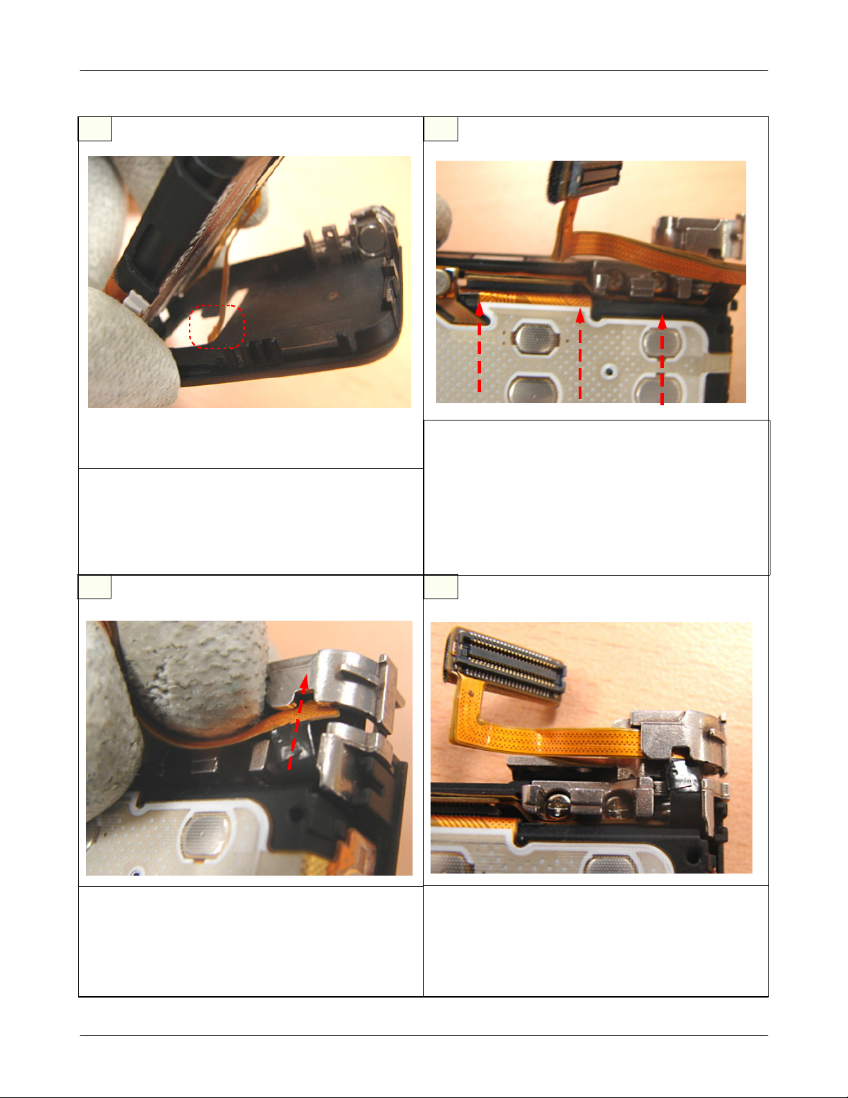
7
Location of BATTERY BRACKT(Step
1)
Put Battery Bracket on the Swing Lower.
caution
※
When putting, inset Touch Key F-PCB through the
hole first.
1)
8
Location of BATTERY BRACKT(Step
1)
Push Battery Bracket to the upper direction like the
direction in the picture.
caution
※
Be careful not to make scratch and molding
1)
damage!
Be careful not to damage the locker.
2)
2)
9 10
Assembly of CON TO CON F-PCB
1)
Step
(
1)
Push CON TO CON F-PCB in the inside of HINGE
caution
※
Be careful of FPCB cutting.
1)
Look at the CON TO CON F-PCB after pushing
※
Not allowed to be positioned on the downside of
HINGE
Assembly of CON TO CON F-PCB(Step
caution
2)
2-17
SAMSUNG Proprietary-Contents may change without notice
This Document can not be used without Samsung's authorization
Main Electrical Parts List
11
Assembly of SWING SIDE BELT
1)
Insert SWING SIDE BELT into LOWER.
12
1)
Put MIC HOLDER on the MIC.
13 14
Assembly of MIC HOLDER
Assembly of SWING UPPER
1)
Put SWING UPPER on the LOWER.
SAMSUNG Proprietary-Contents may change without notice
This Document can not be used without Samsung's authorization
Attachment of TOUCH KEY F-PCB
1)
Attach TOUCH KEY F-PCB following silk line on
the TOUCH KEY PAD.
2-18
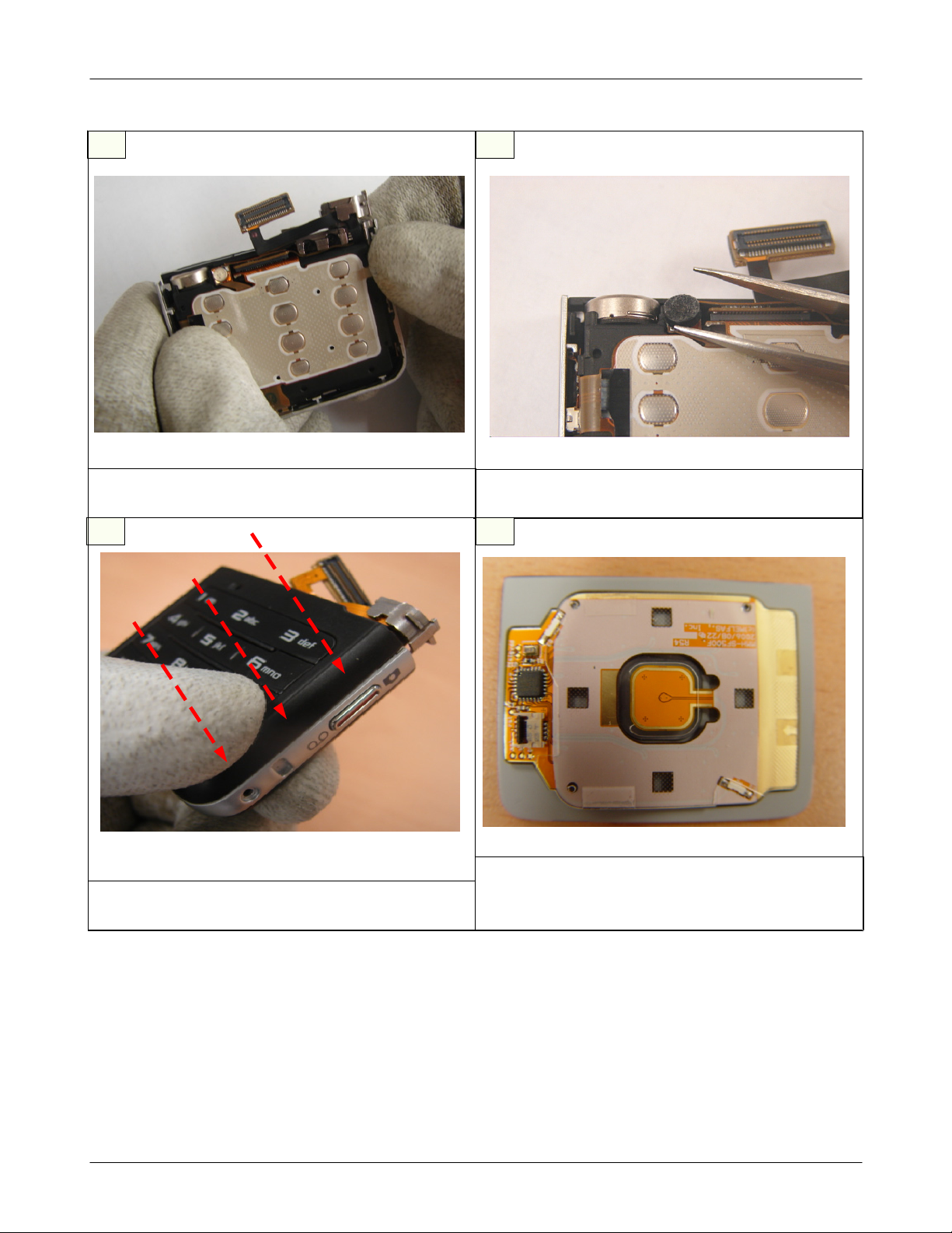
Main Electrical Parts List
15
①
③
Assembly of TOUCH KEY
1~2.
3.
4.
Openning TOUCH KEY CONNECTOR, insert F-PCB to the SILK LINE.
Shut the CONNECTOR after inserting F-PCB.
Attach TOUCH KEY PAD on the SWING LOWER at last.
②
④
16 17
Assembly of SWING SCREW.
1)
Assemble the three point of screw following the
direction.
1)
AttachtheLABELonthetopofSWINGassembly.
Attaching the LABEL
2-19
SAMSUNG Proprietary-Contents may change without notice
This Document can not be used without Samsung's authorization
Main Electrical Parts List
18
Location of
1)
Put
※
LCD MODULE on the REAR COVER.
2.4"
caution
Insert F-PCB into the hall of REAR COVER.
2.4"
LCD
1)
Attach MAIN WINDOW following the picture.
20 21
19
Attachment of MAIN WINDOW
Attachment of Gasket
1)
Attach two gasket following the picture.
SAMSUNG Proprietary-Contents may change without notice
This Document can not be used without Samsung's authorization
Attachment of Tape
1)
Attach two tape following the picture.
2-20
Main Electrical Parts List
22
Assembly of INTENNA
1)
Positioning the Intenna on the REAR COVER,
tighten the SCREW.
23
Attachment of
1)
Removing the vinyl on the back of 1.5" LCD MODULE,
attach the module on the SHIELD COVER.
1.5"
LCD
24 25
1)
Locate NAVI KEY on the FRONT COVER.
Attachment of SUB WINDOW
1)
Attach the SUB WINDOW on the front cover.
※
Locating the NAVI KEY, watch the twelve of RIB.
Location of NAVI KEY
caution
2-21
SAMSUNG Proprietary-Contents may change without notice
This Document can not be used without Samsung's authorization

Main Electrical Parts List
26
Location of SHIELD COVER.
1)
Locate shied cover on the front cover from the top
to the lower.
27
1)
Locate the
follwing the picture.
28 29
Location of SIM COVER
SIM COVER on the SHIELD COVER
Rotating the HINGE
1)
Rotate the HINGE before positioning the SWING assembly.
SAMSUNG Proprietary-Contents may change without notice
This Document can not be used without Samsung's authorization
Assembly of CON TO CON CONNECTOR
1)
1Insert CON TO CON CONNECTOR to PBA following the
picture.
2-22
Main Electrical Parts List
30
Assembly of HINGE
1)
After locating the PBA, locate the SWING HINGE
on the FRONT COVER.
31
1)
Locate the PBA by the hook of FRONT COVER.
32 33
Location of PBA
Arrangement of SWING on the FRONT COVER
1)
Arrange the SWING PART on the FRONT COVER.
SAMSUNG Proprietary-Contents may change without notice
This Document can not be used without Samsung's authorization
Arrangement of SWING on the FRONT COVER
1)
Arrange PBA on the FRONT COVER.
2-23
Main Electrical Parts List
34
Location of SPEAKER
1)
Locate SPEAKER on the FRONT COVER HOLE.
35
Assembly of SCREW
1)
Tightenascrew on the right upper side of PBA.
caution
※
When tightening, Be careful of harm of surrounding
chips.
36 37
Assembly of SUB LCD CONNECTOR.
1)
Insert the SUB LCD CONNECTOR into the socket
on the left side of PBA.
1)
Attach the VOLUME KEY F-PCB on the front cover.
Attachment of VOLUME KEY
2-24
SAMSUNG Proprietary-Contents may change without notice
This Document can not be used without Samsung's authorization
Main Electrical Parts List
38
Assembly of2MEGA CAMERA
1)
Inset2MEGA CAMERA on the soket of the right
and upper side fo PBA.
39
Assembly of Left SIDE BELT
1)
Insert Left SIDE BELT.
caution
※
When inserting, locate HOLD KEY on the HOLD
SWITCH exactly.
40
Assembly of right SIDE BELT
1)
Insert right SIDE BELT from the top to the lower.
caution
※
When inserting, locate exactly on each hook, easpecially the lower hook.
2-25
SAMSUNG Proprietary-Contents may change without notice
This Document can not be used without Samsung's authorization
 Loading...