

Samsung SF 430 Service Manual
SERVICE
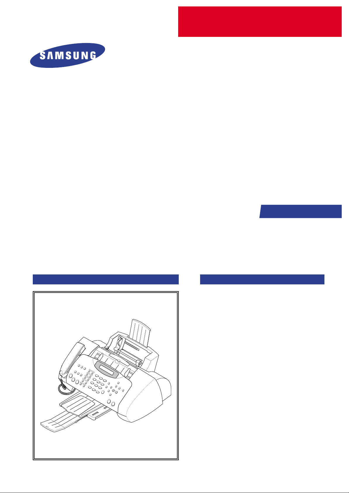
SAMSUNG FACSIMILE
SF-430
Manual
FACSIMILE CONTENTS
1. Precautions
2. Specifications
3. Disassembly and Reassembly
4. Troubleshooting
5. Exploded Views and Parts List
6. Block Diagram
7. Connection Diagram

ELECTRONICS
© Samsung Electronics Co.,Ltd. MARCH
2002
Printed in Korea.
VERSION NO. : 1.01 CODE : JB-0022A
This service manual is also provided on the web,
the ITSELF system Samsung Electronics Co., Ltd.
“http://itself.sec.samsung.co.kr”
- This Service Manual is a property of Samsung Electronics Co.,Ltd.
Any unauthorized use of Manual can be punished under applicable
International and/or domestic law. -

This manual is stated and
provided for service description.
All rights reserved. Any parts of the
information in this manual are prohibited
from free duplication, use or translation
without prior written approval except in
cases allowed by the Copyright Act.
Specifications are subject to change without
prior notice.
Copyright (c) 2002. 3.
Samsung Electronics Digital Printing CS Group
1-1
Samsung Electronics
1. Precautions
Please read the following carefully to prevent any accidents and not to damage the unit during service.
1-1 Safety Precautions
1-2 Precautions on Disassembly and Reassembly
1. Safety Precautions
There are some electric or machinery parts with safety
related property. If the parts replaced are different from
the original, the safety may not function. Even if the part
could allow higher voltage than that of the part used, do
not replace it and use a regular product clarified in specifications.
2. Be careful not to leave a switch, a cover or a safety device
out when reinstalling or assembling the product after
repair.
3. Replacing Precautions
Do not change or add parts as you like. You cannot benefit from such a remodeled product at your will during the
term of guarantee.
4. You must replace overheated or damaged parts or cords
with regular products. Please solve the problem causing
any damage or overheating and troubles beforehand.
Especially mind the safety on the part with this
mark.
You must use regular parts described in specifications for the parts inflammable and where the current can be flown. Otherwise any hazard such as
an electric shock or a fire could occur .
Very careful precautions should be taken when replacing
parts. Before replacing, please check cables because you
cannot put the cables that you removed for replacing parts
into the proper place if you would not make sure of where
they were connected and in which condition.
Please do the following before disassembling
for a repair or replacement of parts.
1. Pull out paper cassette, printer cartridge installed.
Especially careful not to be scratched by the surface of
developer or not to expose them to light.
2. Turn the power switch off.
3. Take out the power plug, printer cable from the printer.
4. Use only the same type of part as original when replacing
parts.
5. Do not force to open or fasten plastic material components.
6. Be careful that small parts such as screws should not get
in the printer.
7. When disassembling, assembling, also observe small
components are located in place.
8. If you uncover and turn the machine over to replace some
parts, toner or paper particles may contaminate the LSU
window. Protect the LSU window with clean paper.
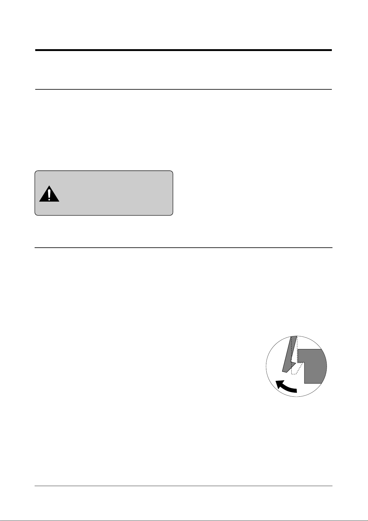
Releasing Plastic Latches
Many of parts are held in
place with plastic latches.
The latches break easily :
release them carefully.
To remove such parts, press
the hook end of the latch
away from the part to which
it is latched.

Certain semiconductor devices can be easily damaged by
static electricity. Such components are commonly called
“Electrostatically Sensitive (ES) Devices”, or ESDs.
Examples of typical ESDs are: integrated circuits, some field
effect transistors, and semiconductor “chip” components.
The techniques outlined below should be followed to help
reduce the incidence of component damage caused by static electricity.
1. Immediately before handling a semiconductor component or semiconductor-equipped assembly, drain off any
electrostatic charge on your body by touching a known
earth ground. Alternatively, employ a commercially available wrist strap device, which should be removed for your
personal safety reasons prior to applying power to the unit
under test.
2. After removing an electrical assembly equipped with
ESDs, place the assembly on a conductive surface, such
as aluminum or copper foil, or conductive foam, to prevent electrostatic charge buildup in the vicinity of the
assembly .
3. Use only a grounded tip soldering iron to solder or desolder ESDs.
4. Use only an “anti-static” solder removal device. Some solder removal devices not classified as “anti-static” can
generate electrical charges sufficient to damage ESDs.
5. Do not use Freon-propelled chemicals. When sprayed,
these can generate electrical charges sufficient to damage ESDs.
6. Do not remove a replacement ESD from its protective
packaging until immediately before installing it. Most
replacement ESDs are packaged with all leads shorted
together by conductive foam, aluminum foil, or a comparable conductive material.
7. Immediately before removing the protective shorting
material from the leads of a replacement ESD, touch the
protective material to the chassis or circuit assembly into
which the device will be installed.
8. Maintain continuous electrical contact between the ESD
and the assembly into which it will be installed, until completely plugged or soldered into the circuit.
9. Minimize bodily motions when handling unpackaged
replacement ESDs. Normal motions, such as the brushing together of clothing fabric and lifting one’s foot from a
carpeted floor, can generate static electricity sufficient to
damage an ESD.
1-3 ESD Precautions
Precautions
1-2
Samsung Electronics
CAUTION:
Be sure no power is applied to the chassis or circuit, and observe all other safety precautions.
Precautions
1-3
Samsung Electronics
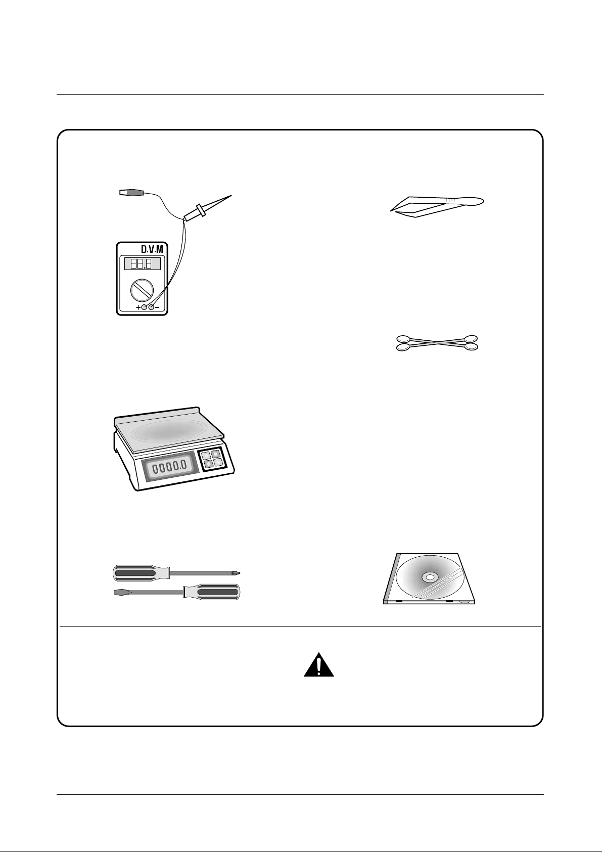
1-4 Tools for Troubleshooting
The following tools are recommended for safe and smooth troubleshooting described in this service manual.
DVM(Digital Volt Meter)
Standard: Indicates more than 3 digits.
Electronic Scale
Standard: Equipment to check the weight of consumables supplied by Samsung Electronics.
(The gram unit can be measured.)
Driver
Standard: "-" type, "+" type (M3 long, M3 short,
M2 long, M2 short).
Pinset
Standard: For general home use, small type.
Cotton Swab
Standard : For general home use, for medical ser-
vice.
Cleaning Equipments a IPA(Isopropyl
Alcohol)dry cloth or a soft stuff neutral
detergent.
Software(Driver) installation CD ROM
Mind your hands not to be touched when you
disassemble and reassemble PBAASS'Y, such as
the main board.
Note
1
2
3
4
5
6
7
Samsung Electronics
2-1
2. Specifications
2-1 Printer Engine
Technology
Speed Color
Mono
Resolution
Color
Mono
Printing Width
Feeding Method
Automatic
Manual Tray
Emulation
Printer Driver
Interface
Thermal Inkjet
2-pen & Print Head Swapping Type
7 ppm at Draft Mode
14 ppm at Draft Mode
True 600 x600 dpi (2400 x1200 dpi Addressable)
True 600 x600 dpi (2400 x1200 dpi Addressable)
203mm
100 Sheets of 20lb cut sheets ( Max 10mm )
No
Host Based Printing (GDI)
Windows 98/ME , Windows 2000/XP
USB(without HUB Mode) and Centronics 1284
2-2 Ink Cartridge
Babbage mono standard Birch color
Model No. M50 C60
Print Head 208 nozzles 192 nozzles
Ink type Pigment Dye
Ink Color Black (Babbage) Color (Birch)
Ink Yield Standard about 600 sheets (5% Pattern, A4) about 275 sheets (15% Pattern, A4)
High yield about 1075 sheets (5% Pattern, A4) about 275 sheets (15% Pattern, A4)
Samsung Electronics
Specifications
2-2
2-3 Facsimile
(*3) Monochromatic CCITT NO. 1 CHART can be saved by 80 sheets per 1.0M Byte.
Compatibility
Scan method
Scan width
Scan Resolution
Transmission Speed
Scan Method
ADF
Guide
Stacker
Paper Tray
Modem Speed
Coding Method
LCD
Resolution & Type
Contrast
Capacity (*3)
Back-up Time
Confidential
Forced Memory Tx.
Memory Rx.
ITU-G3
CIS , Sheet-feed
Max. 216mm, Effective : 210mm
600 x 1200 dpi
3 sec (standard resolution , MMR , 33.6 kbps)
True color , 256 gray ,Block/White
30 sheets of 20lbs
Document Input Guide
Document Output Stacker/Paper Stacker
BIN Type (Without Manual Tray)
33.6 Kbps
MH, MR, MMR, JPEG, Error Correction Mode
2 Lines Each of 16 Characters
- Standard : 200 x100 dpi
- Fine : 200 x200 dpi (Default)
- Superfine : 300 x 300 dpi
- Color : 200 x 200 dpi
(Standard : Low quality, Fine : High quality compression)
Lightest/Lighten/Normal/Darken/Darkest/
2 Mbyte
Minimum 30 minutes
No
Yes
Automatic reception when paper empty.
GENERAL
SCANNING
MEMORY
Samsung Electronics
Specifications
2-3
Facsimile (continued)
TELEPHONE Speed Dial 70 Locations
Chain Dial No
On-hook Dial Yes, 1-Key
Last Number Redial Yes, 1-Key
Auto Redial Yes
Hold & Mute No
Pause Yes, Use Redial Key
Ringer Volume S/W Option Setting (4Steps)
Tone/pulse Select S/W Option setting
DRPD US : Yes, Other Country : No
REPORT TX/RX Journal Yes
& LIST Image TCR Yes, Reduction of First Page Sent by Memory Tx
System Data Yes
Tel Number List Yes
Self Test Yes
COPY Multipage Copy Upto 99 Pages
Gray Scale 256 Levels
Resolution 600 X 600 dpi
Speed Mono 10 cpm
Color 5 cpm
Zoom Range 20 % ~ 400 %
TEL I/F Answering I/F Yes
Ext. Phone 1-jack, Extension Phone Transfer
OTHERS Sensors Paper Jam, Cover Open
Real Time Clock Yes
RTI Y es
Samsung Electronics
Specifications
2-4
2-4 Scanner
Compatibility TWAIN
Technology Platen CIS
Light Source for Color CIS RGB LEDs (Line Order Control)
2-5 Power & Size
2-6 Accessaries
Power Source 220V~240V, 50/60Hz, 0.5A
Dimensions (W X D X H) With the paper support and out tray retracted :439.8 X326.6 X 192.9 mm
With the paper support and out tray extended :439.8 X 602.5 X 192.9 mm
Weight (Packed Weight) 5.6Kg (8.0Kg: Packed Weight)
Tel Line
Power Cord
FAX Driver
Ink Cartridge
Manual
Carrier Sheet
1EA
1EA
1 CD - ROM
INK-M50 (MONO) 1EA, INK-C60 (COLOR) 1EA
Yes
No
3-1
3. Disassembly and Reassembly
3-1 General Precautions on Disassembly
When you disassemble and reassemble components, you must use extreme caution. The close proximity of
cables to moving parts makes proper routing a must. If components are removed or replaced, any cables
disturbed by the procedure must be replaced as close as possible to their original positions. Before removing
any component from the machine, note the cable routing that will be affected.
Whenever servicing the machine, you must perform as follows:
1. Check to verify that documents are not stored in memory.
2. Move the printer cartridge to far right to cap the nozzle.
3. Unplug the power cord.
4. Use a flat and clean surface.
5. Replace only with authorized components.
6. Do not force plastic-material components.
7. Make sure all components are in their proper position.
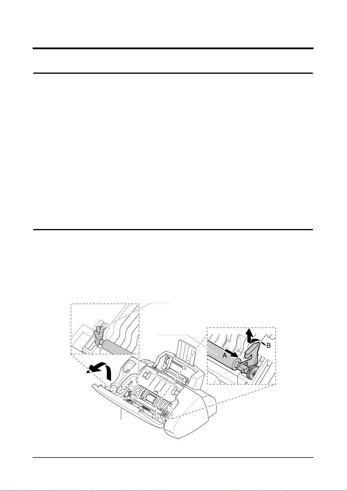
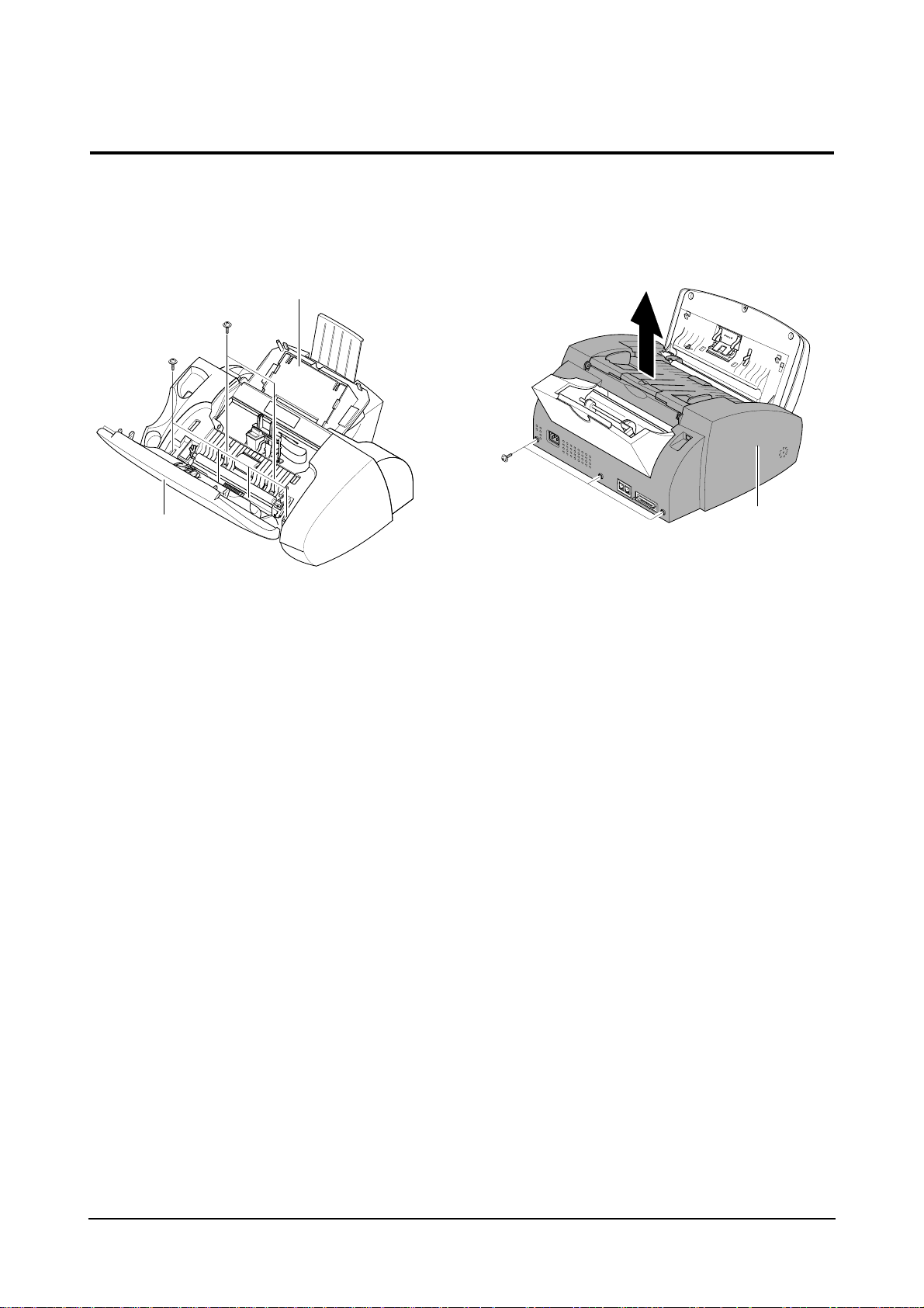
1. Lift the control panel using hand.
2. Push the bushing on both ends of the roller
slightly inward, then rotate it until it reaches the
slot as shown below. Then lift the roller out.
Note : Check the roller for any dirt. If dirty, wipe it off
with soft cloth dampened with IPA(Isopropyl
Alcohol). If the roller is heavily worn, replace
it with a new one.
3-2 White Roller Ass’y
Bushing
White Roller
Control Panel
Disassembly and Reassembly
3-2
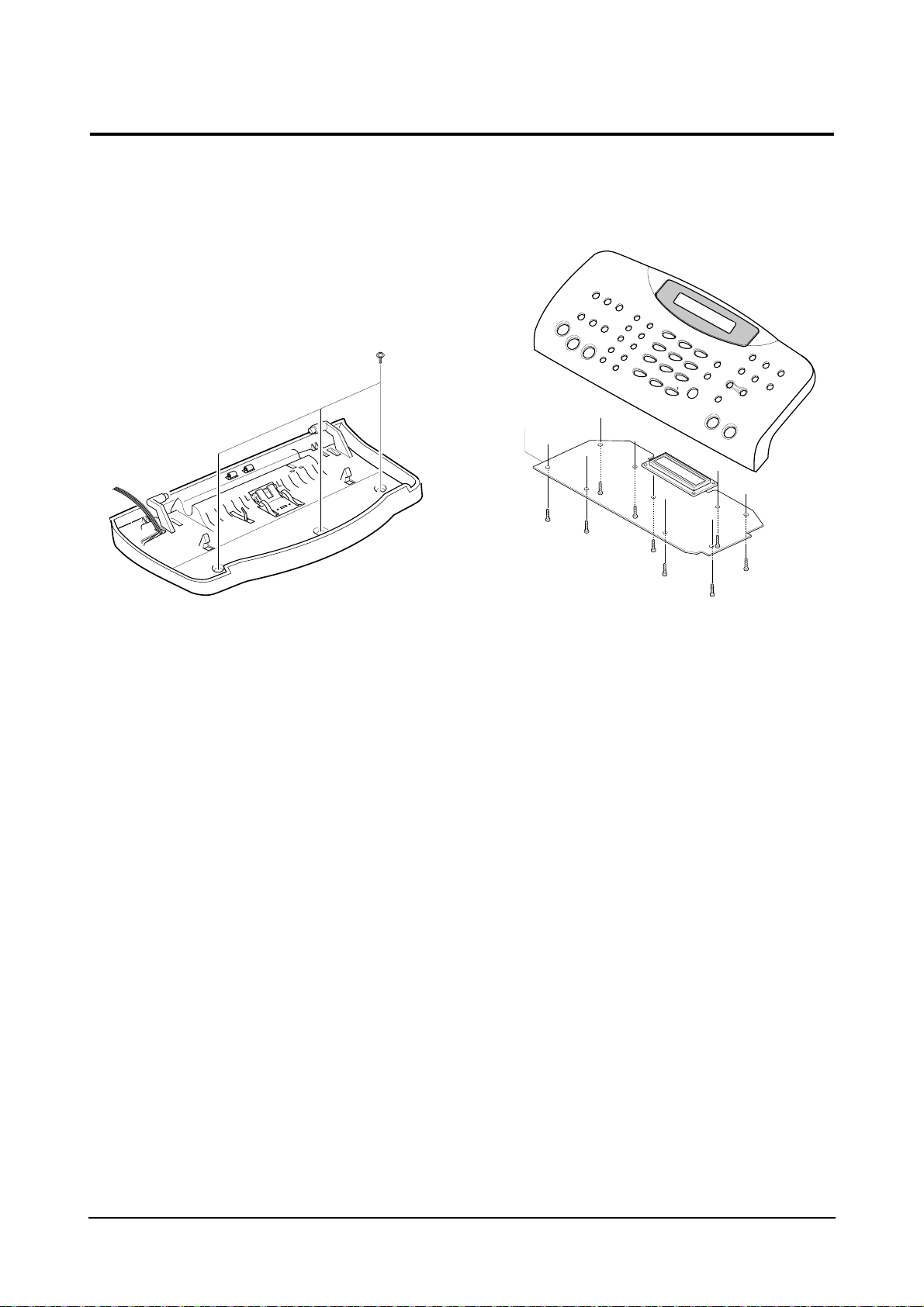
3-3 Top Cover Ass’y
1. Lift the control panel and open the print cartridge compartment cover. Remove the white
roller ass’y. Remove the six screws shown
below.
2. Remove the three screws shown below and
take out the top cover ass’y.
Cartridge Compartment cover
Control panel
Top cover ass’y
Disassembly and Reassembly
3-3
3-4 Base Ass’y
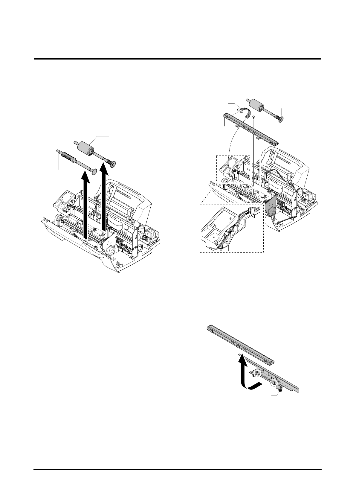
3-4-1 Rollers (ADF Roller, Exit Shaft)
1. Before you disassemble the rollers, you should
remove:
– Top Cover Ass’y (see page 3-3)
2. Take out the rollers from the base ass’y.
Note : Clean the surface of the rollers with IPA
(Isopropyl Alcohol). After wiping them, you
must dry them completely.
3-4-2 CIS (Contact Image Sensor)
1. Before you disassemble the CIS, you should
remove:
– Top Cover Ass’y (see page 3-3)
2. Remove the drive roller as described in ‘3-4-1
Rollers’.
3. Remove the one screw securing the CIS ass’y
and unplug the CIS harness. Take out the CIS
ass’y .
4. Unlatch two point then remove the CIS from the
bracket.
Note: Be careful not to lose the springs.
Note : Check the glassy surface of the CIS for any
stain or scratch. If stained, wipe off with IPA
(Isopropyl Alcohol). If it is heavily stained or
scratched, replace it with a new one.
ADF Roller
Exit shaft
CIS
Spring
Bracket
CIS harness
CIS ass’y
ADF Roller
Disassembly and Reassembly
3-4
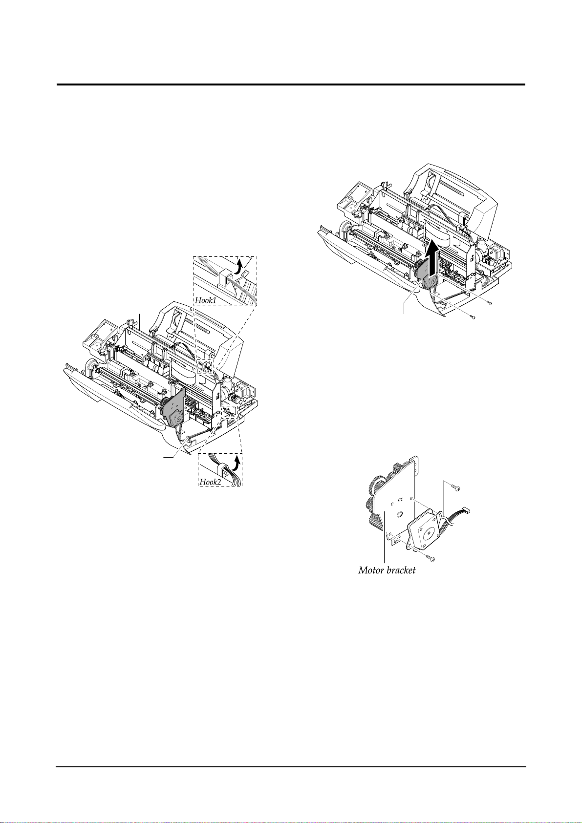
1. Before you disassemble the Scan Motor, you
should remove:
– Top Cover Ass’y (see page 3-3)
2. Unplug the motor connector from the main PBA.
Make sure the harness is released from five
hooks securing the harness as shown below.
3. Remove the two screws as shown below and
take out the scan motor ass’y.
4. Remove the two screws securing the motor to
the motor bracket.
3-4-3 Scan Motor
Motor harness
Main PBA
Scan motor ass’y
Disassembly and Reassembly
3-5
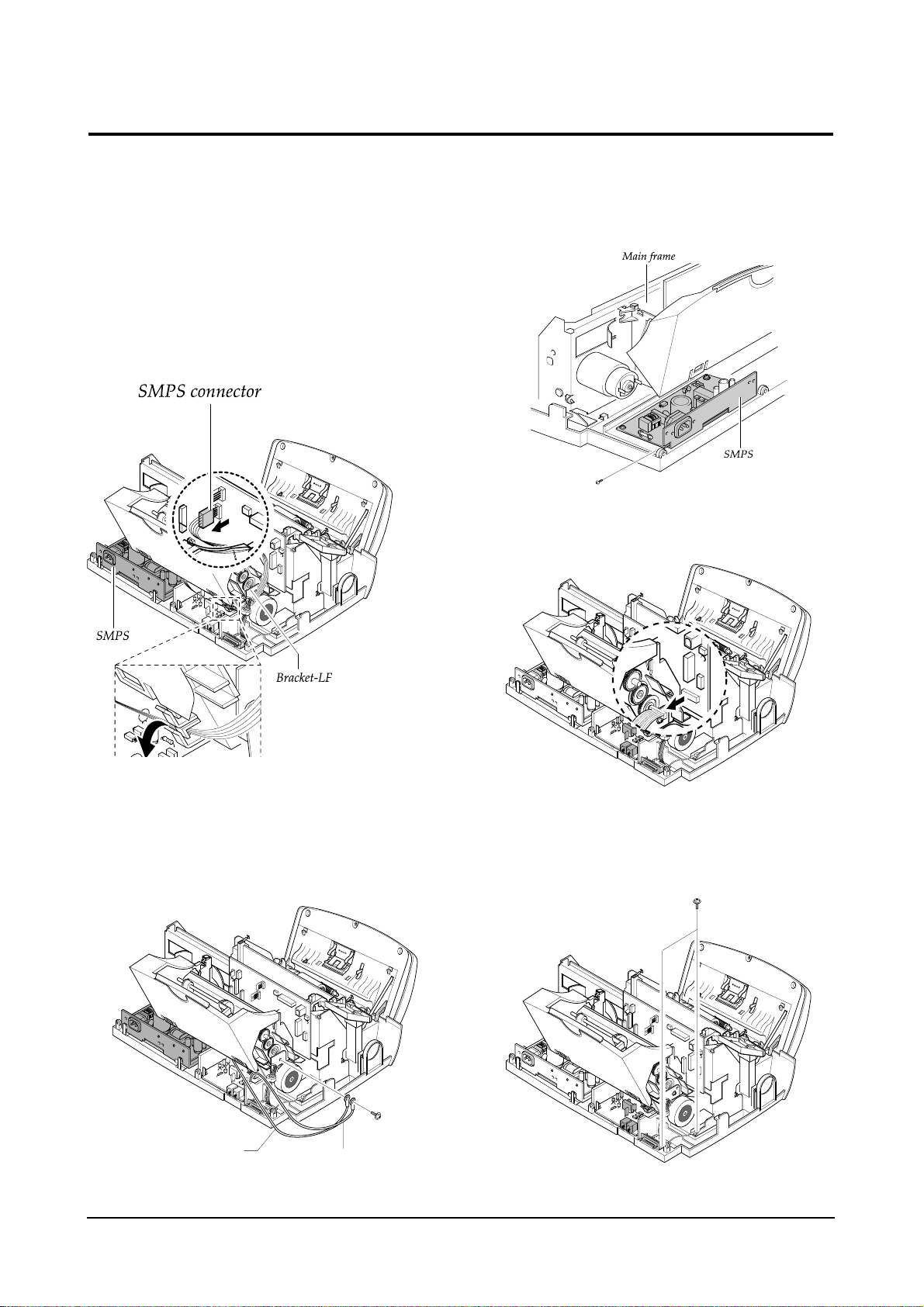
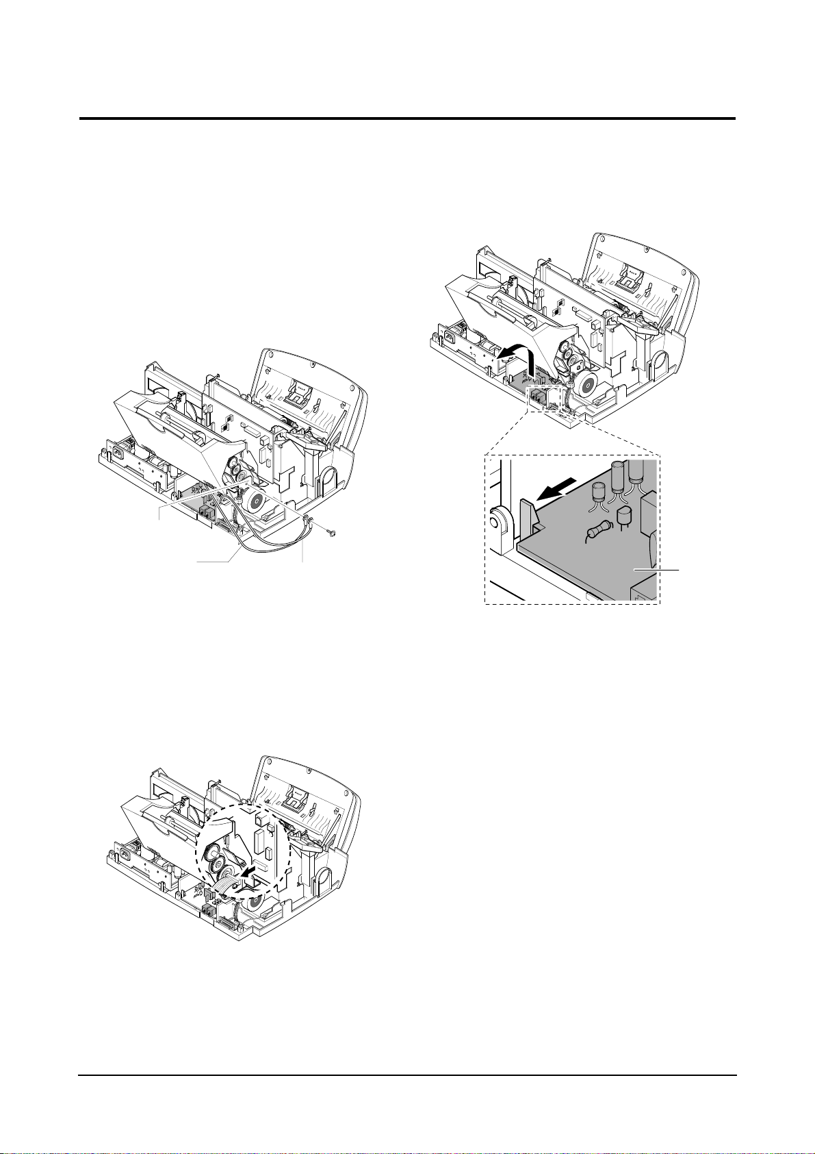
3-4-4 SMPS and Centronics B’d
1. Before you disassemble the SMPS and
Centronics B’d, you should remove:
– Top Cover Ass’y (see page 3-3)
2. Unplug the SMPS connector from the Main PBA.
Make sure the harness is released from the hook
as shown below.
3. Remove the one screw securing the ground
wires to the bracket as shown.
4. Remove the one screw securing and remove the
SMPS to the Main Frame.
5. Unplug the Centronics B’d connector from the
Main PBA.
6. Remove two screws securing and then remove
centronics B’d.
SMPS ground wire
LIU ground wire
Disassembly and Reassembly
3-6
3-4-5 LIU PBA
1. Before you disassemble the LIU PBA, you
should remove:
– Top Cover Ass’y (see page 3-3)
2. Remove the one screw securing the ground
wires to the bracket.
3. Unplug the LIU connector from the Main PBA.
4. Pulling the snap fits locking the PBA outward,
push up the LIU PBA.
5. Unplug all the connectors from the LIU PBA.
Bracket-LF
SMPS ground wire
LIU ground wire
LIU PBA
Disassembly and Reassembly
3-7
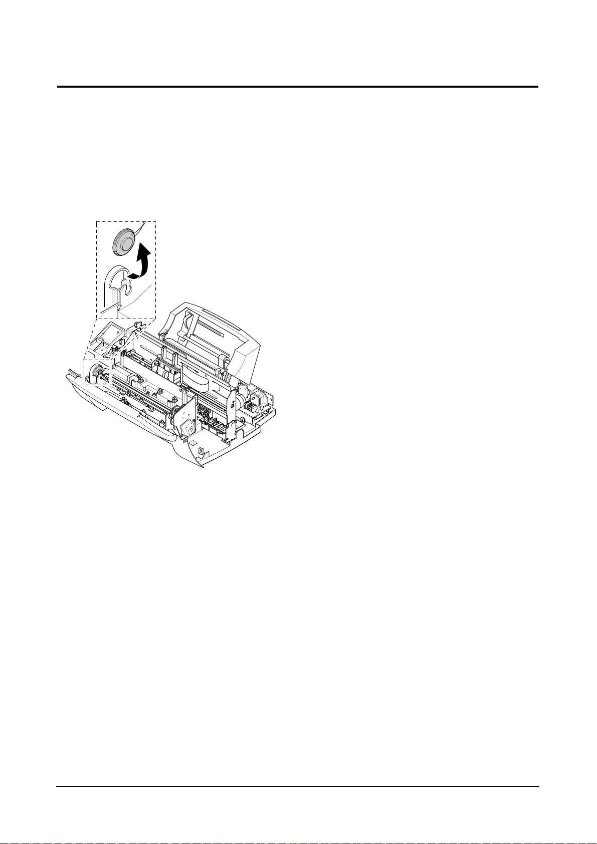
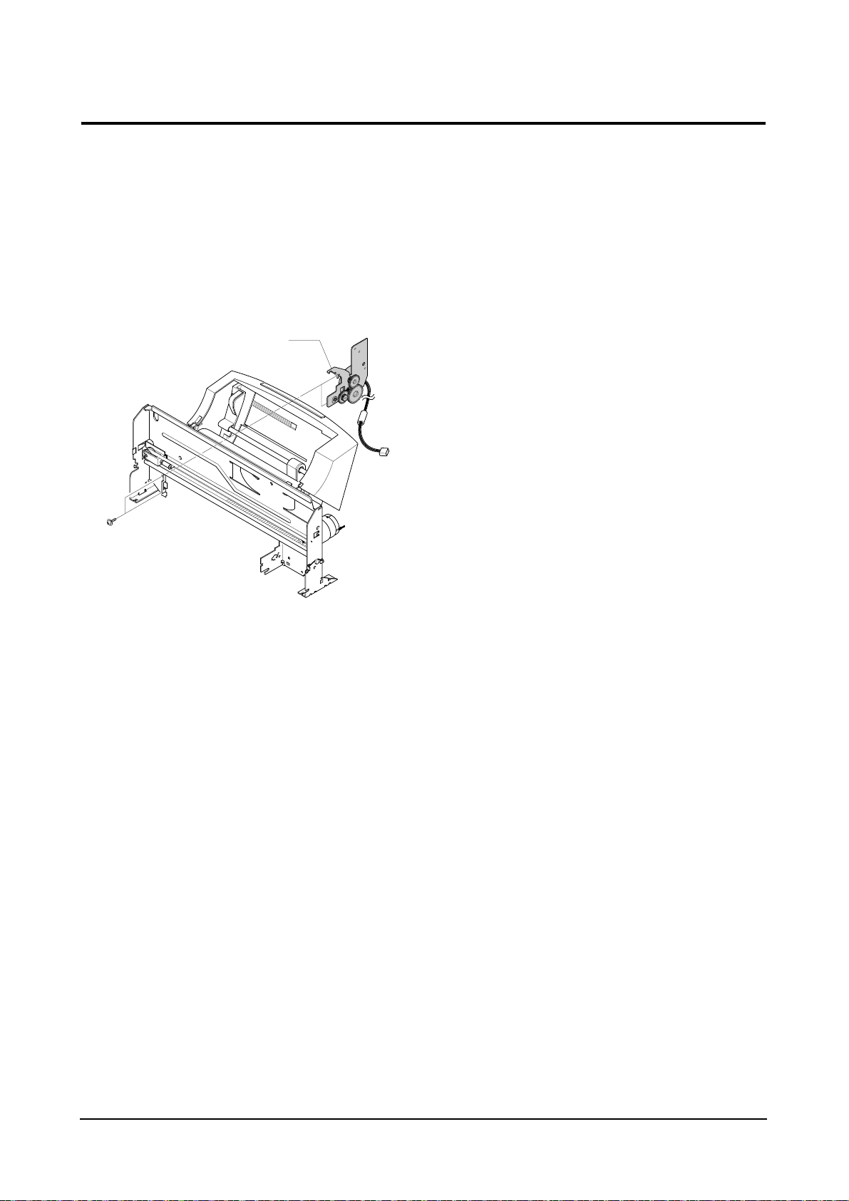
3-4-6 Speaker Ass’y
1. Before you disassemble the speaker , you should
remove:
– Top cover Ass’y (see page 3-3)
2. Remove the speaker .
Disassembly and Reassembly
3-8
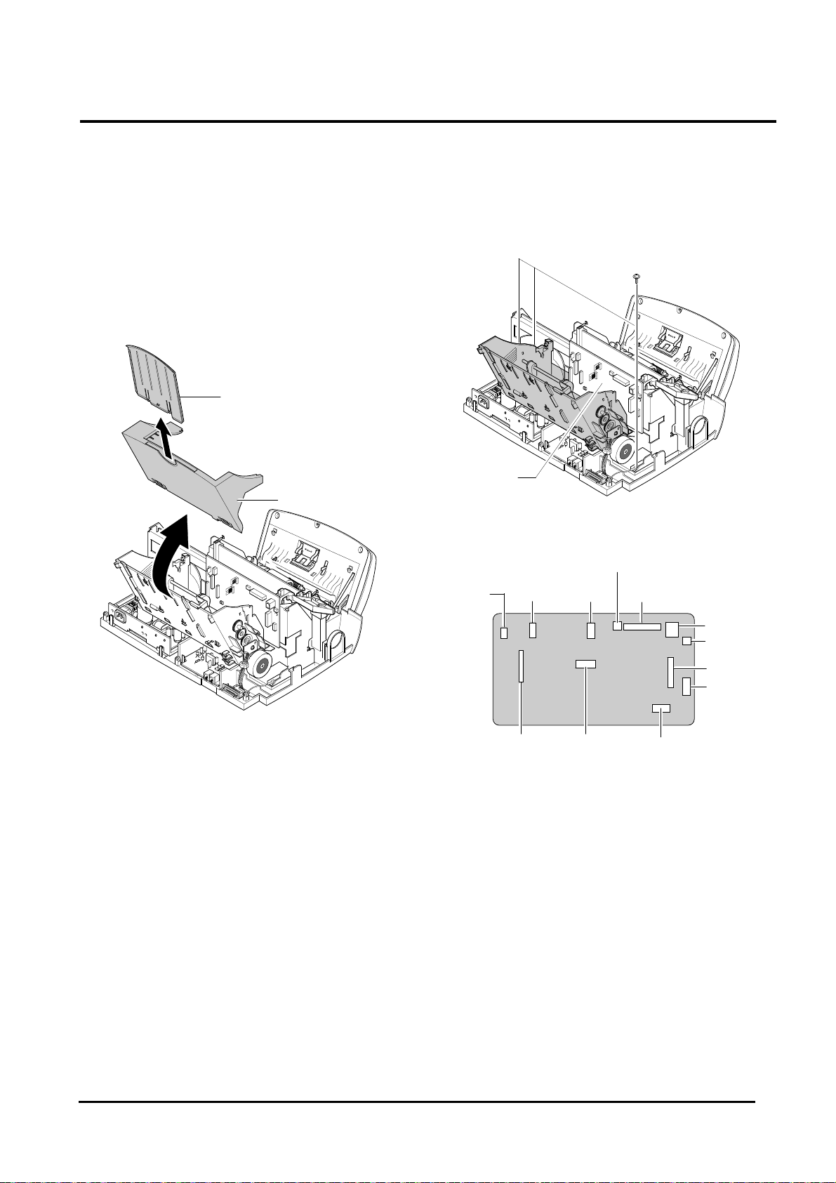
3-5 OPE Ass’y
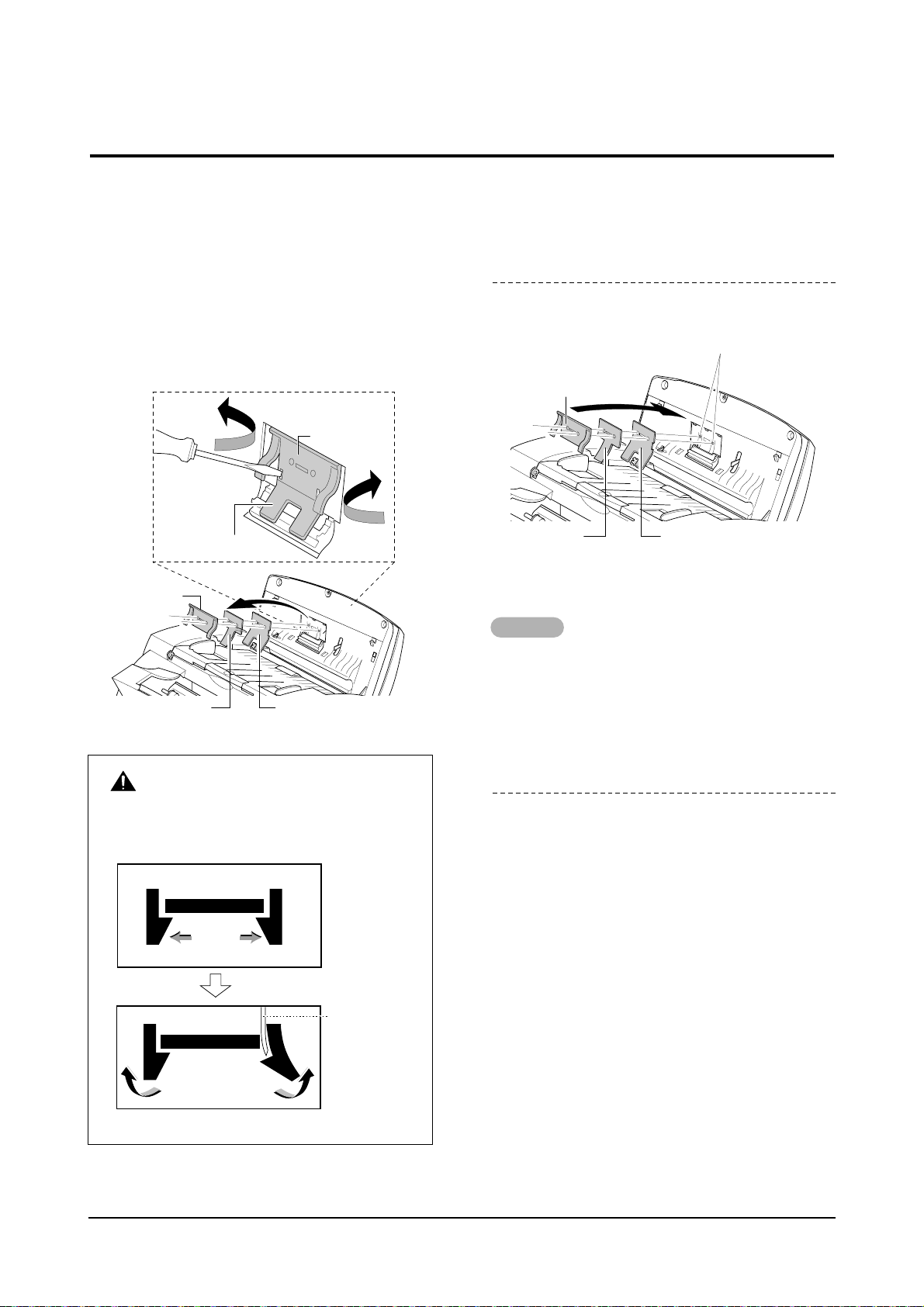
3-5-1 ADF Rubber Pad
1. Open the OPE unit.
2. Insert a flat blade screw driver and pinset into the
slot as shown below, and release the latches.
Take out the Holder Rubber, Sheet ADF and the
Rubber ADF.
Notes
• When you reassemble the them, be sure that the
Rubber ADF, Sheet ADF and Holder Rubber fit
into the guide boss and the Holder Rubber latches fit into the corresponding hole. Then push firmly until it clicks.
3. Clean the surface of the rubber pad with IPA
(Isopropyl Alcohol). After wiping it, be sure to dry
it. Check the rubber wear. If the wear reaches 1/2
its original thickness, replace it with a new one.
Holder Rubber
Holder Rubber
Rubber ADF
Rubber ADF Sheet ADF
Holder Rubber
Rubber ADF
Guide Boss
Sheet ADF
Pinset or
Screw Driver
Safely Precautions :
Do not force to open or fasten plastic material
components.
Disassembly and Reassembly
3-9
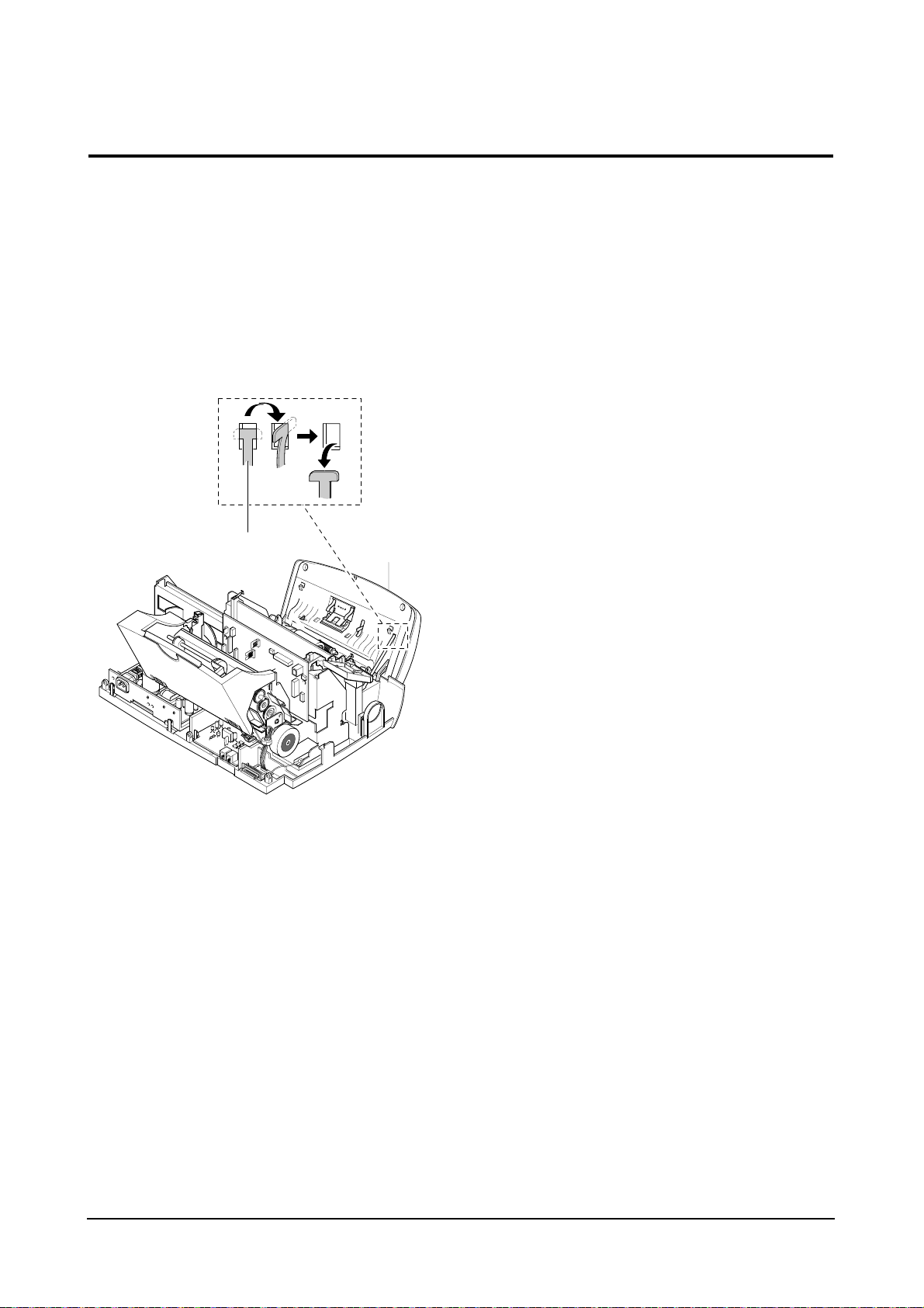
3-5-2 OPE Unit
1. Before you disassemble the OPE unit, you should
remove:
– Top Cover Ass’y (see page 3-3)
2. Turn the tie stopper 90 degrees as shown below
and take out the OPE unit.
OPE unit
Tie stopper
Disassembly and Reassembly
3-10
3-5-3 OPE PBA
1. Before you disassemble the OPE PBA, you
should remove:
– OPE Unit (see page 3-5-2)
2. Remove the four screws securing the OPE unit.
3. Remove the nine screw and take out the PBA
with LCD.
Notes:
• Do not turn the OPE unit upside down after you
remove the screws securing the PBA. Keys and
rubber contacts may be separated and easily lost.
• When you reassemble the OPE unit, make sure
the keys are in correct position.
• When you reassemble the PBA, secure the screws
according in the order of the number printed on the
PBA.
• After reassembling, operate the machine to make
sure it works properly.
• After reassembling, make sure the LCD is not
blocked.
OPE PBA
Disassembly and Reassembly
3-11
3-6-1 Printer Unit
1. Before you disassemble the printer unit, you
should remove:
– Top Cover Ass’y (see page 3-3)
2. Take out the Guide Extension.
3. Take out the Dummy ASF.
4. Remove the three screws securing the printer
unit, and unplug the eight connectors from the
Main PBA. Take out the printer unit.
Note: When you reassemble the unit, do not pinch
or short the wire harness.
Guide Extension
Dummy ASF
Main PBA
CR motor
TX motor
LF motor CIS
Cover Open Sensor
USB
Speaker
LIU
OPE
SMPS
Parallel
(IEEE1284)
Print Head
(CR Ass’y)
3-6 Printer Ass’y
Disassembly and Reassembly
3-12
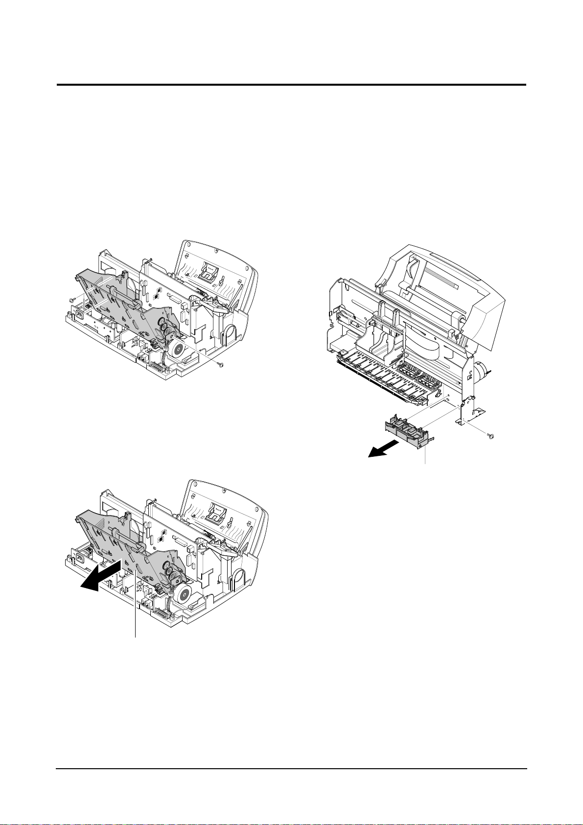
3-6-2 ASF Feeder Ass’y
1. Before you disassemble the ASF feeder ass’y,
you should remove:
– Top Cover Ass’y (see page 3-3)
2. Unplug all connectors from the Main PBA and
remove the three screws shown below.
3. Remove the ASF feeder ass’y from the printer
unit by pushing the tab inward and take the ass’y
out in the direction of arrow.
3-6-3 Home Ass’y
1. Before you disassemble the home ass’y, you
should remove:
– Printer Unit (see page 3-6-1)
2. Remove one screw and pushing the both ends
of the home ass’y, take out the ass’y in the
direction of arrow.
ASF feeder ass’y
Home ass’y

Disassembly and Reassembly
3-13
3-6-4 Carriage Ass’y
1. Before you disassemble the carrier ass’y, you
should remove:
– Printer Unit (see page 3-6-1)
2. Take out FRC cable from the main PBA, take out
2 CR springs that fix CR shaft, and then separate
carriage Assembly .
3-6-5 Main PBA
1. Before you disassemble the Main PBA, you
should remove:
– Top Cover Ass’y (see page 3-3)
2. Remove the two screw securing the Main PBA.
3. Unplug all connectors from the Main PBA.
4. Pull the sensor lever towards you and take out
the Main PBA.
CR shaft
Carriage ass’y
FPC cable
Sensor Lever
Disassembly and Reassembly
3-14
3-6-6 Base Frame Ass’y
1. Before you disassemble the base frame ass’y,
you should remove:
– Printer Unit (see page 3-6-1)
– Holder Roller Ass’y
2. Remove the friction ass’y, then take out the
actuator feed.
3. Pull out the base frame ass’y.
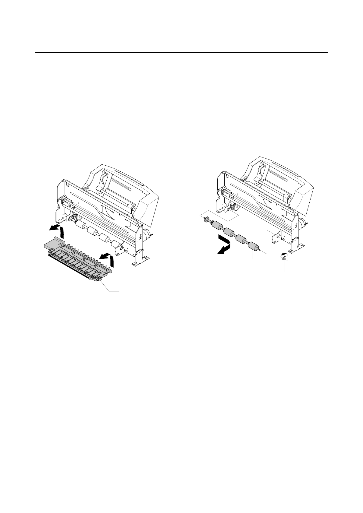
3-6-7 Feed Roller Ass’y
1. Before you disassemble the feeder roller ass’y,
you should remove:
– Printer Unit (see page 3-6-1)
– Base Frame Ass’y (see page 3-6-6)
2. Remove the bearing feed from the main frame.
Pull the feeder roller in the direction of arrow and
take it out.
Base frame ass’y
Feed Roller
Bearing Feed
Disassembly and Reassembly
3-15
3-6-8 Line Feeder Bracket Ass’y
1. Before you disassemble the line feeder bracket
ass’y, you should remove:
– Printer Unit (see page 3-6-1)
– Feed Roller Ass’y (see page 3-6-7)
2. Remove the two screws and take out the LF
bracket ass’y.
LF bracket ass’y
4-1
Samsung Electronics
4. Troubleshooting
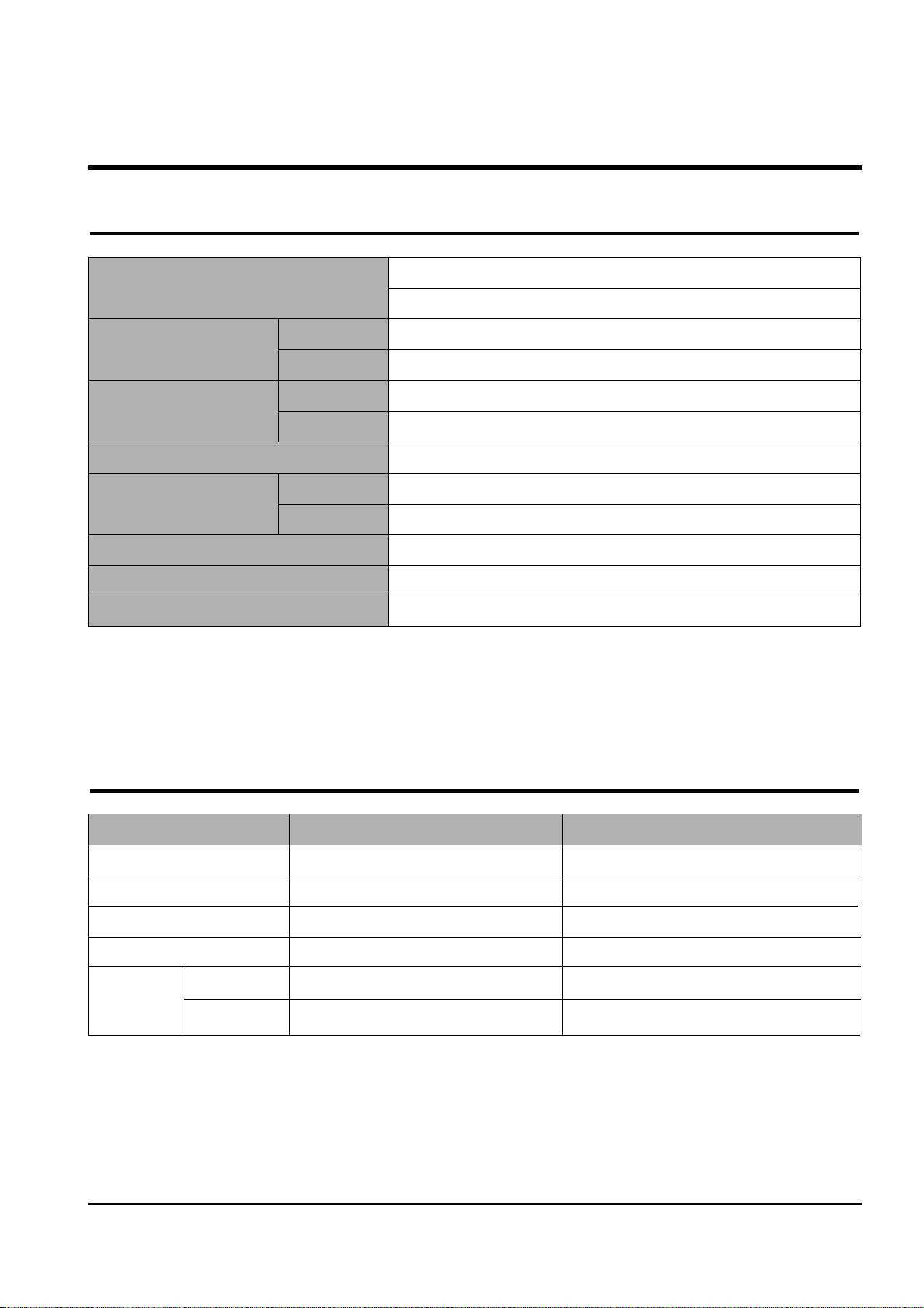
4-1 Setting-up System in User Mode
FUNCTION ITEM CONTENT DEFAULT
SYSTEM SETUP FAX NUMBER/NAME FAX NUMBER
FAX NAME
DATE FORMAT EUROPE/USA EUROPE
DATE/TIME
LANGUAGE ENG/GER/FRE/ITA/SPA/POR/DUT ENGLISH
DISCARD SIZE 0~30MM 20 MM
RINGER VOLUME OFF/LOW/MID/HIGH MID
ALARM VOLUME ON/OFF ON
KEY VOLUME ON/OFF ON
DIALING MODE TONE/PAUSE TONE
CLOCK MODE 24HOURS/12HOURS 24 HOURS
USB MODE FAST/SLOW FAST
SET DEFAULT CONTRAST
QUALITY
COPY PAGE
ZONE RATE
RESOLUTION
FAX SETUP SEND FORM MEMORY ON/OFF ON
SENDING CONFIRM ON/OFF/ERROR ERROR
FAX PAPER SIZE LETTER/A4/LEGAL A4
AUTO REDUCTION ON/OFF ON
SAVE TOLLTIME START TIME _ _ : _ _
RINGS TO ANSWER 1-7 TIME 1
STAMPRCV. NAME ON/OFF OFF
RCV. START CODE * _ * 9
DRPD MODE ON/OFF OFF
ECM MODE ON/OFF ON
CALLER ID ON/OFF OFF
AUTO JOURNAL ON/OFF ON
COPY SET UP PAPER SIZE LETTER/A4/LEGAL A4
PAPER TYPE PLAIN/INKJET/PHOTO/TRANSP ARENCY PLAIN PAPER
COLLATE ON/OFF OFF
ADVANCED FAX BROADCASTING
DELAYED FAX
PRIORITY FAX
SEND POLLING
ADD SCHEDULE
CANCEL SCHEDULE
REPORT/HELP HELP LIST
SENT JOURNAL
RECEIVED JOURNAL
PHONEBOOK
SEADING CONFIRM
SCHEDULE INFORM
SYSTEM DATA
SELF TEST
CID LIST
GROUP DIAL SET
MEMORY CLEAR FAX NUMBER/NAME
DIAL/SCHEDULE
JOURNAL
DEFAULT SETUP
MAINTENANCE CLEAN CARTRIDGE
ALIGN CARTRIDGE
VIEW INK LEVEL "COLOR : _/8 , BLOCK : _/8"
ADJUST SHADING
REMOTE TEST ON/OFF OFF
4-2
Troubleshooting
Samsung Electronics
4-2-2 Setting-up System in TECH MODE
4-2 Tech Mode
4-2-1 HOW TO ENTER TECH MODE
In TECH MODE, the technician can check the machine and perform various test to isolate the cause of a malfunction.
To enter the TECH MODE, press MENU, #, 1, 9, 3, 4 in sequence, and the LCD briefly displays ‘T’, the machine has entered
service (tech) mode.
While in TECH MODE, the machine still performs all normal operations.
To return to normal user mode, press MENU, #, 1, 9, 3, 4 in sequence again, or turn the power off, then on by unplugging
and plugging the power cord.
Options changed while in TECH MODE do not remain changed unless you clear the machine’s memory.
Because the explanation of the User Mode items is already mentioned at the User guide in detail, It will not be described at
Service manual.
FUNCTION ITEM CONTENT DEFAULT
SYSTEM SETUP MODEM TEST
DTMF TEST
ROM TEST Display ROM version
PROGRAM DOWNLOAD
AGING TEST
FAX SETUP MODEM SPEED 2.4/4.8/7.2/9.6/12.0/14.4/28.8/33.6 26.4 KBPS
SEND FAX LEVEL 0~15 -12 DBM
RCV. FAX LEVEL 40~50 -43DBM
DTMF HIGH LEVEL 00~15 8
DTMF LOW LEVEL 00~15 11
PAUSE TIME 1~9 4 SEC
ERROR RATE 5%/10% 10%
MAKE/BREAK RATIO 40/60~33/67 33/67
CNG DETECT COUNT 1~4 2
AUTODIALTIMEOUT 30~150 55
DIAL MODE LOC. USER/TECH USER
COPY SET UP The same items as user mode.
ADVANCED FAX The same items as user mode.
REPORT/HELP HELP LIST
SENT JOURNAL
RECEIVED JOURNAL
PHONEBOOK
SEADING CONFIRM
SCHEDULE INFORM
SYSTEM DATA
SELF TEST
CID LIST
PROTOCOL DUMP
SHADING PRINT
ASF TEST
GROUP DIAL SET The same items as user mode.
MEMORY CLEAR ALL MEMORY CLEAR
MAINTENANCE CLEAN CARTRIDGE
ALIGN CARTRIDGE
VIEW INK LEVEL "COLOR : _/8 , BLOCK : _/8"
ADJUST SHADING PATTERN OUTPUT
REMOTE TEST ON/OFF OFF

4-3
Troubleshooting
Samsung Electronics
SYSTEM SETUP
• MODEM TEST :
Use this feature to hear various transmission signals to the telephone line from the modem and to check the modem. If no transmission signal sound is heard, it means that the modem part of
the main board is poor.
• DTMF TEST :
DTMF (Dual Tone Multi Frequency) signal. When you press any
key on the number keypad including * and #, you will hear the
corresponding key tone.
• ROM TEST :
Use this feature to test the machine'S ROM. The result and the
software version appear in the LCD display .
• PROGRAM DOWNLOAD :
Use this feature to download a new upgraded ROM file
from a PC which is connected to the machine with a parallel cable (IEEE 1284).
< Download >
1. Connect printer to PC with a parallel cable(IEEE 1284.)
2. Select the PROGRAM DOWNLOAD function at the TECH
MODE.
3. Input COPY/B FILENAME PRN at the MS-DOS and push
the ENTER key .
(filename : the latest ROM file name when the downloading)
4. After the download is completed, the system will be automatically initialized.
< Note >
Must perform the ADJUST SHADING after downloading a new
ROM to adjust the standard value of the CIS.
• AGING TEST :
The function is to test the capacity of product in the production progress. Service person doesn't need to use it.
FAX SETUP
• MODEM SPEED :
You can set the maximum modem speed. Communication is done
with modem speed automatically set at lower speed when communicating with the modem with lower speed since communication is
done on the standard of the side where modem speed is low for
transmission/reception. It is better set 26.4KBPS as default setting.
• SEND FAX LEVEL:
Y ou can set the level of the transmission signal. T ypically , the Tx level
should be under -12 dBm.
Caution : The Send Fax Level is set at the best condition in the ship-
ment from factory . Never change settings arbitrarily.
• RCV FAX LEVEL:
- You can set the level of the receiving signal.
- The reception level may be too low due to the cable losses.
- If it is set to -43 dBm, the reception sensitivity will be between 0
and -43 dBm. If it is set to -48 dBm, the reception sensitivity will
be between 0 and -48 dBm.
Caution : The Send Fax Level is set at the best condition in the ship-
ment from factory . Never change settings arbitrarily.
• DTMF HIGH LEVEL :
Select high frequency level when dialing in the MF mode.The input
range is between 00~15dBm.
Caution : The Send Fax Level is set at the best condition in the ship-
ment from factory . Never change settings arbitrarily.
• DTMF LOW LEVEL :
Select high frequency level when dialing in the MF mode.The input
range is between 00~15dBm.
Caution : The Send Fax Level is set at the best condition in the shipment
from factory. Never change settings arbitrarily.
• P AUSE TIME :
Pause time mean delay time (unit: second) inserted between dial
number signal and the next number of signal in the automatic dial
(One touch, Speed dial, Redial) and the manual dial.
Caution : The Send Fax Level is set at the best condition in the shipment
from factory . Never change settings arbitrarily.
• ERROR RA TE :
- When the error rate is about to be over the setting value, the
Baud rate automatically lowers up to 2400 bps to make the error
rate remain below the setting value.
- You can select the rate between 5% and 10%.

4-4
Troubleshooting
Samsung Electronics
• Make/Break RATIO :
Select the dial pulse make and break time: 40-60 or 33-67.
Caution : Send Fax Level is set at the best condition in the shipment from
factory. Never change settings arbitrarily.
• CNG DETECT COUNT :
The function is to control the CNG TONE cognition times for
entering receiving mode from the AUT O MODE or ANS/FAX
MODE.
• AUTODIAL TIMEOUT :
It is the certain time to be converting to ST ANDBYin case of
a receiver doesn't answer when caller uses AUTO DIAL,
such as ONE-TOUCH/SPEED DIAL/RESERVED SENDING
and etc.
• DIAL MODE LOC. :
The function is to take care the DIALMODE SETTING, which
is set in at USER MODE or TECH MODE differently by coun-
tries.
If you select the USER MODE, you can choose DIAL MODE
OPTION at the USER MODE.
4-2-3 REPORT/HELP
HELP LIST
It shows a brief description on the machine's basic functions
and commands.
Use it as a quick reference guide
SENT JOURNAL.
This journal shows a specific information concerning transmission activities, the time and dates of up to 40 of the most
recent transmissions.
RECEIVED JOURNAL
This journal shows a specific information concerning reception activities, the time and dates of up to 40 of the most
recent receptions.
PHONEBOOK
It lists all telephone numbers that have been stored in the
machine.
SENDING CONFIRM
It shows the result of the last send operation.
SCHEDULE INFORM
This list shows a specific information on the documents
currently stored for delayed transmission. It provides the
operation number, starting time, type of operation, etc.
SYSTEM DATA
This list provides a list of the user system data settings and
tech mode settings.
4-5
Troubleshooting
Samsung Electronics
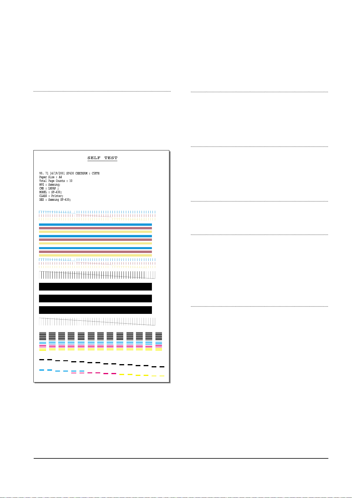
SELF TEST
Using this pattern printout, you can check if the printer
mechanism is functioning properly. Examine the pattern
and look for a break in the diagonal line. If the diagonal
lines are not broken, the printer mechanism is functioning
properly .
CID LIST
In the country which supports CALLER ID, information of
the dates and numbers of calls is stored when RING is
receiving.
(CALLER ID : it is a telephone service to send a caller's
number to the receiver.)
PROTOCOL DUMP
This list shows the sequence of the CCITT group 3 T.30
protocol during the most recent sending or receiving operation. Use this list to check for send and receive errors. If a
communication error occurs while the machine is in TECH
mode, the protocol list will print automatically.
SHADING PRINT
With this print, you can check the scanning elements of the
CIS Contact Image Sensor.
ASF TEST
The function is to test the function of ASF (AUTO SHEET
FEEDER), and it is needed in the production progress.
Service person doesn't need to use it.
4-2-4 Memory Clear
ALL MEMORY CLEAR
The function resets the system as its very first condition as
setting in at the factory.
This function is needed to operate to reset the system to the
initial value when the product is abnormally operated or
malfunction. All the values are returned to the default values, and all the information, which set in by user, will be
erased.
4-2-4-1 Method to use TECH MODE
Perform the MEMORY CLEAR at the TECH MODE.
4-2-4-2 Method to use CANCEL BUTTON
1. Turn off the power.
2. Keep pushing the CANCEL button till the MEMORY
CLEARING is shown up at the LCD panel.
3. Turn on the power.
A1
P1 P2 P3 P4 P5 P6 P7 P8 P9 P10 P11 P12 P13 P14 P15 P16
A2 A3 A4 A5 A6 A7 A8 A9 A10 A11 A12 A13
 Loading...