

Page 1

SF -330 Series Graphic Print Bar
Service Guide
Graphic print bar with print cartridge installed
Samsung Electronics Confidential
Copyright Samsung Electronics Company 2002 Revision 1.0 July 12, 2002
Page 2

Samsung Electronics Confidential
SF-330 Series Graphic Print Bar Service Guide
SF-330 Series Graphic Print Bar
Service Guide
Contents
1 Product Overview ...........................................3
1.1 Carriage Drive System....................................................... 3
1.2 Carriage Movement ........................................................... 4
1.3 Print Cartridge Maintenance............................................... 4
2 Troubleshooting............................................. 5
2.1 Print Quality...................................................................... 6
2.2 Print Cartridges ................................................................. 9
3 Part Replacement.........................................11
3.1 Carriage Motor................................................................11
3.2 Service Station Parts .......................................................12
3.3 Cap and Wiper Replacement............................................12
Figures
Figure 1-1. Carriage drive system .................................................... 3
Figure 1-2. Installing the print cartridge .............................................5
Figure 1-3. Service station and components ..................................... 5
Figure 2-1. Example of missing dots shown as partial printed rows
(white stripes) in the printout............................................................ 7
Figure 2-2. Properly installed print cartridge ...................................... 7
Figure 2-3. Cleaning the electrical contacts on the carriage (left)
and print cartridge (right).................................................................. 8
Figure 2-4. Removing crusted ink from the print cartri dge................... 9
Figure 2-5. Use before date on print cartridge package....................10
Figure 3-1. Left side of the carriage bar showing the two motor
mount screws...............................................................................12
Figure 3-2. Service station viewed from the bottom showing the
gear which releases the carriage lock .............................................12
Figure 3-3. Service station (viewed from the top) showing the
direction to push the cap/ wiper rotating assembly............................ 12
Figure 3-4. Removing the wiper with a screw driver .........................13
Figure 3-5. The back side (a) and the left end (b) of the print bar
and removal of the service station from the front (c).........................14
3.4 Service Station Removal and Replacement....................... 14
3.5 Encoder Strip Spring ....................................................... 15
3.6 Encoder Strip ..................................................................16
3.7 Carriage Rod Lock ..........................................................18
3.8 Carriage Rod .................................................................. 19
3.9 Carriage Assembly and Drive Belt .................................... 19
4 Appendix......................................................22
4.1 Assembly Illustration ........................................................ 22
4.2 Troubleshooting Flowchart ............................................... 23
4.3 General Media Specifications ...........................................23
Figure 3-6. Right end (a) and the left end (b) of the print bar,
showing the flanges that hold the encoder spring. ............................ 15
Figure 3-7. Right end of the print bar with rod lock in down position .. 16
Figure 3-8. Right end with arrow showing clockwise rotation of rod
lock into position ........................................................................... 16
Figure 3-9. Front of the print bar showing the flex circuit and the
encoder strip behind the carriage....................................................17
Figure 3-10. Right end of the print bar showing how to release the
rod lock........................................................................................ 18
Figure 3-11. Pushing the belt tensioner toward the carriage
compresses the spring to release the tension on the drive belt..........20
Figure 3-12. Lifting the carriage assembly off of the chassis .............20
Figure 3-13. Clear plastic flex clamp that secures the circuit to the
chassis......................................................................................... 21
Figure 3-14. Bottom of print bar showing belt attachment to the
carriage........................................................................................ 21
Figure 3-15. Drive belt gear and the flange that holds it in place ....... 21
Figure 4-1. Exploded view of a graphic print bar with part notations .. 22
Figure 4-2. Troubleshooting flowchart ............................................ 23
Tables
Table 2-1. Print cartridge life specification....................................... 10
Revision History
Revision Date Revision description
1.0 July 10,2002 Document released
Copyright Samsung Electronics Company 2002
Page 2
Revision 1.0; 23-Jul-02
Page 3

SF-330 Series Graphic Print Ba r
Samsung Electronics Confidential
SF-330 Series Graphic Print Bar Service Guide
Service Guide
1 Product Overview
The product is a 600 dpi color inkjet raster graphics print bar designed for integration into an OEM’s phone fax or
plain paper (MFP) fax product. The product consists of a small carriage assembly and carriage drive system,
which use s a short (47 mm high) replaceable inkjet print cartridge to provide the OEM with the ability to create a
small form factor product with optimal reliability and performance. The product ‘s electrical design includes print
control ASICs to allow compatibility with the OEM’s (or 3rd party) fax controllers. This allows the OEM
flexibility to design either a standalone phone fax or an MFP product with a PC interface.
1.1 Carriage Drive System
The carriage drive system includes several components, which control carriage movement, maintain the print
cartridge, and enhance print quality (see Figure 1-1).
Electrical
interconnect
contacts
Service station motor
Figure 1- 1. Carriage drive system
Carriage and encoder
Rotating service
assembly (wipers,
caps, etc)
Service station
Carriage motor
Flex circuit
Electrical interface with
logic PCA on the printer
Chassis
Carriage belt
Pulley assembly
and belt tensioner
Carriage rod
Encoder strip
Carriage rod lock
Copyright Samsung Electronics Company 2002
Page 3
Revision 1.0; 23-Jul-02
Page 4

SF-330 Series Graphic Print Ba r
Samsung Electronics Confidential
SF-330 Series Graphic Print Bar Service Guide
Service Guide
1.2 Carriage Movement
The carriage is belt driven, using a 3-to-1 gear set for coupling to the motor. The gear set minimizes side-loading
of the motor, because the belt is not attached directly to the motor. The belt is supported and driven at the left end
by the belt gear, and supported at the right end by the idler pulley. The belt is mounted to a clip that snaps into the
back of the carriage.
The top of the carriage travels across the carriage bar on a flat bearing that maintains the tilt of the carriage. The
bearing provides low overall friction with the steel carriage chassis. A sintered bronze bushing impregnated with
lubricant provides both low friction levels and environmental stability with changes in temperature or humidity.
Interface oil holds the friction level constant. The oil is a synthetic, low vapor-pressure oil that is compatible with
the plastic parts and resistant to evaporation.
The carriage rocks slightly, as a function of clearance between the carriage rod and the bushing on the bottom of
the carriage, as well as the bearing at the top of the carriage. To minimize the impact of carriage rocking, relative
to the encoder system, a mylar encoder strip is positioned closely to the nozzle plate of the print cartridge. The
mylar material is resistant to fingerprints, paper dust, and so forth. It is slightly sensitive to temperature and
humidity, so a flat spring (on the right side of the steel carriage bar) maintains tension on the encoder strip.
The quadrature optical encoder and a decoupling capacitor are soldered onto the flex circuit on the rear side of the
carriage. The flex circuit comes out through the front side of the carriage, where it splits and folds over itself in
order to travel within the compact carriage path.
The flex circuit carries signals for the encoder system, as well as drive voltage for the print cartridge. Signal lines
for the print cartridge terminate at the flex-circuit contacts on the interconnect pad in the front of the carriage.
These contacts interface with contacts on the back of the print cartridge.
1.3 Print Cartridge Maintenance
The top of the carriage contains a spring latch for the print cartridge. The spring latch provides tension for
consistent snap-in of the print cartridge. The print cartridge should only be replaced when the carriage is in the
designated service position, which is controlled from the product’s front panel.
When installing a print cartridge, the bottom portion of the print cartridge should be installed into the carriage
assembly as shown in Figure 1-2. Once the bottom is seated in the carriage, push the top portion of the cartridge
toward the carriage until it snaps into place beneath the spring latch. Always ensure that the electrical contacts
inside the carriage are clean. Do not handle or touch the contacts because oil from the user’s fingers can corrode
the electrical contacts (see Figure 2-3 in section 2.1.2.1 for carriage and cartridge contact cleaning instructions).
The service station, at the left end of the carriage path, contains two wipers and two nozzle caps to provide
servicing and capping for either a monochrome or a color print cartridge (see Figure 1-3). The caps and wipers are
mounted on a rotary assembly, which incorporates a micro-switch for accurate positioning.
Copyright Samsung Electronics Company 2002
Page 4
Revision 1.0; 23-Jul-02
Page 5

SF-330 Series Graphic Print Ba r
Samsung Electronics Confidential
SF-330 Series Graphic Print Bar Service Guide
Service Guide
Spring latch
Wiper
Cap
Electrical
contacts
Figure 1-2. Installing the print cartridge Figure 1-3 . Service station and components
Motor
Rotary service
assembly
The service station wipes and caps the orifice plate of the print cartridge after each print job and at predefined set
points to ensure long product life. The orifice plate on the print cartridge is wiped to remove any excess ink, which
could harden and cause the nozzles to clog. The print cartridge is then capped to prevent the ink nozzles from
drying out. The cap vents into a rubber base through a vent line, so that all atmospheric interactions with the
nozzles occur through the vent (see Table 2-1 in section 2.2.2 for cartridge life information).
2 Troubleshooting
The following tools are recommended for servicing and troubleshooting the graphics print bar:
• Lint free swabs (cotton swabs are not recommended )
• Torx #'s T8 & T10 drivers
• Small flat head screwdrivers
• Needle-nose pliers
Copyright Samsung Electronics Company 2002
Page 5
Revision 1.0; 23-Jul-02
Page 6

SF-330 Series Graphic Print Ba r
Samsung Electronics Confidential
SF-330 Series Graphic Print Bar Service Guide
Service Guide
2.1 Print Quality
This section provides possible causes and solutions for print quality problems.
2.1.1 Poor Print Quality
Unacceptable print quality can include:
• Faded, faint, fuzzy, or smeared printout
• Inconsistent print density
• Missing dots or White Lines in Print (see section 2.1.2 )
For print quality problems, check the following:
1. The print cartridge can cause print quality problems. For print cartridge problems, see section 2.2 in this
chapter.
2. The paper can cause print quality problems.
a. Verify that the paper meets the specifications of a high quality plain paper copier media for standard
monochrome printing. If color printing is being performed on a media suited only to text printing, the
quality may be unacceptable. For high quality color printing, media that is designed for high-quality color
inkjet printing is recommended. SEE MEDIA SPECIFICATION in APPENDIX 4.3
b. Some papers that meet the paper specifications may not provide acceptable print quality. Try a different
brand or type of paper.
c. Turn the stack of paper over and try printing on the other side of the paper. (Most papers have a
recommended print side, which is identified on the paper packaging. If print quality improves, no further
troubleshooting is necessary.
Note: The product is designed to work well with most types of paper, although variables in paper
manufacturing and composition can significantly affect print quality and paper handling. Most paper
manufactured for high -quality photocopying yields good results for general monochrome printing. For
high density, high quali ty color printing, paper should be tested before large quantities are purchased,
in order to ensure desirable performance. SEE MEDIA SPECIFICATION in APPENDIX 4.3
3. Heavy concentrations of ink can cause the paper to buckle and produce smeared printouts. Try a different type
of paper specifically suited for inkjet printing which can absorb more ink when printing.
4. Ink from damp and buckled paper can leave excess ink on components in the paper path. Clean ink residue
from mechanism components if they are conta minated by wet ink.
5. Crusted ink on the print cartridge nozzles can cause smearing and missing dots (see section 2.1.2.2 about
cleaning crusted ink from the nozzles).
6. Damage to the encoder strip can cause print quality problems. Check for problems with the encoder strip and
spring. If necessary, replace affected parts (see sections 3.5 and 3.6).
Copyright Samsung Electronics Company 2002
Page 6
Revision 1.0; 23-Jul-02
Page 7

SF-330 Series Graphic Print Ba r
Samsung Electronics Confidential
SF-330 Series Graphic Print Bar Service Guide
Service Guide
2.1.2 Missing Dots
Figure 2-1. Example of missing dots shown as partial printed rows (white stripes) in the printout
If any rows of dots are missing on printouts (as shown in Figure 2-1), check for the following problems:
1. The print cartridge may be past its expiration date, running out of ink, or faulty. If so, replace the print
cartridge (see section 2.2 for details about print cartridge problems).
2. The print cartridge may not be making good electrical contact with the carriage assembly. Make sure that the
print cartridge is seated and pressed securely against the carriage contacts. Remove and reinstall the print
cartridge, making sure that the cartridge snaps into the carriage assembly, as shown in Figure 2-2.
Figure 2-2. Properly installed print cartridge
3. The carriage contacts or print cartridge contacts may be dirty (see section 2.1.2.1 about cleaning the electrical
contacts).
4. The print cartridge may have been stored uncapped and out of the mechanism, which can cause a severely
Copyright Samsung Electronics Company 2002
Page 7
Revision 1.0; 23-Jul-02
Page 8
SF-330 Series Graphic Print Ba r
Samsung Electronics Confidential
SF-330 Series Graphic Print Bar Service Guide
Service Guide
dried out, clogged nozzle. (see section 2.1.2.2 about cleaning the orifice plate and print cartridge nozzles).
If the ink cartridge is only missing a few dot rows, the cartridge may have a damaged or scratched nozzle.
If the nozzle appears scratched or damaged in any way, replace the cartridge.
5. There may be a hardware problem. Check the following:
a. The flex circuit (between the carriage assembly and the logic PBA) may not be making good contact.
Reinstall the flex circuits into connectors on the logic PBA.
b. The carriage assembly may be faulty. Check for problems with the carriage assembly. If necessary,
replace the carriage drive system. Refer to the procedure in section 0.
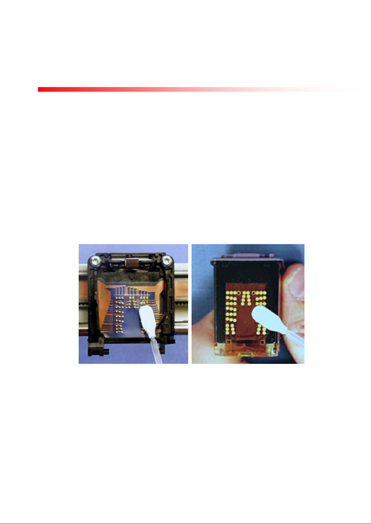
2.1.2.1 Cleaning the Carriage Contacts and Cartridge Contacts
1. Use only lint-free swabs moistened with water. Do not use cotton swabs.
2. Clean the contacts as shown in Figure 2-3.
Caution: Do not clean the print cartridge nozzles or orifice plate with swabs.
3. Let the contacts dry after cleaning.
4. Reinstall the print cartridge into the carriage assembly.
Figure 2 -3. Cleaning the electrical contacts on the carriage (left) and print cartridge (right)
2.1.2.2 Cleaning Crusted Ink from Print Cartridge Nozzles
Storing an uncapped print cartridge outside of the service station can cause a crust of ink on the nozzles.
Do not install an ink-crusted print cartridge into the product.
Caution
Use care during cleaning to avoid staining your hands or clothes with ink from the print cartridge.
1. Hold the print cartridge by the top of the cartridge.
Copyright Samsung Electronics Company 2002
Page 8
Revision 1.0; 23-Jul-02
Page 9

SF-330 Series Graphic Print Ba r
Samsung Electronics Confidential
SF-330 Series Graphic Print Bar Service Guide
Service Guide
2. Scrape dried ink off of the orifice plate into a trash container, using the edge of an index card or other rigid
paper stock (see Figure 2-4).
Index paper or rigid card stock
Crusted ink
Figure 2- 4. Removing crusted ink from the print cartridge
3. Follow the host printer’s instructions to initiate a printing self -test to produce a page of printed information.
• If dots are not missing toward the end of the printout, the print cartridge was successfully restored to
operating condition.
• If dots are missing toward the end of the printout, removing dried ink did not restore print cartridge
operation. Replace the print cartridge.
2.2 Print Cartridges
The graphics print bar uses consumer replaceable print cartridges.
Warning: Print cartridge ink contains chemical substances, which may be harmful if swallowed. Keep new
and used cartridges out of reach of children.
Caution: Do not use refilled print cartridges. Attempting to refill a print cartridge can cause a sudden drainage
and/or leakage of ink, which can damage the product and possibly personal property.
2.2.1 Print Cartridge Care
1. Keep unused print cartridges sealed in their original packaging. When replacing a print cartridge, install the
new cartridge promptly.
2. Do not turn the product off with the print cartridge out of the service station (left end of the carriage path). The
service station cap seals the print cartridge nozzles from exposure to air, to minimize the formation of dried ink
in the nozzles.
3. Do not allow the print cart ridge contacts and nozzles to touch any surface or object, including your fingers.
Skin oil and dust can cause print quality or missing dots problems.
4. Store print cartridges at room temperature.
Copyright Samsung Electronics Company 2002
Page 9
Revision 1.0; 23-Jul-02
Page 10

SF-330 Series Graphic Print Ba r
Samsung Electronics Confidential
SF-330 Series Graphic Print Bar Service Guide
Service Guide
2.2.2 Print Cartridge Expiration
Using print cartridges that are past their expiration date can cause print quality problems. The print cartridge life
specification is shown in the following table:
Table 2-1. Print cartridge life specification
Ink cartridge
M40, C40 18 Months 180 Days
Sealed in original package
(shelf life)
The open life specification of the cartridge is valid for use in an office environment, with a printing frequency of at
least once a month.
To determine if a print cartridge is past its expiration date, read the use before date printed on the box and ensure
the print cartridge is sealed in its original packaging. The print cartridge should be installed before the date shown
on the package (see Figure 2-5). The print cartridge expiration date is also printed on the front of the cartridge
body.
Open, maintained (capped)
in service station
Use before date
Figure 2 -5. Use before date on print cartridge package
2.2.3 Causes for Short Print Cartridge Life
There are several causes for short print cartridge life, which are discussed in this section.
1. Printed pages containing graphics or dense print have a higher percentage of ink coverage than specified for
average print cartridge life when printing in text mode. The percentage of ink coverage on printed pages has a
significant impact on the number of pages per print cartridge. Heavy concentrations of ink reduce the number
of pages per print cartridge.
2. The print cartridge may be past its expiration date.
3. The printing device may have been turned off with the print cartridge out of the service station and the nozzles
uncapped, leaving them exposed to the atmosphere. This could lead to crusted ink on or in the nozzles may
lead to a shorter print life (see section 2.1.2.2 for removing crusted ink). This can also cause misdirected
nozzles if ink is allowed to harden on the nozzle plate. This is again caused by the product being turned off
Copyright Samsung Electronics Company 2002
Page 10
Revision 1.0; 23-Jul-02
Page 11

SF-330 Series Graphic Print Ba r
Samsung Electronics Confidential
SF-330 Series Graphic Print Bar Service Guide
Service Guide
with the print cartridge out of the service station for a long period of time allowing the nozzle plate to dry
out. If the print out has small white lines (caused by either a missing nozzle or a clogged or misdirected nozzle)
clean the print head nozzl e by scraping the excessive ink off and then reinstall the cartridge into the product.
If the cartridge servicing routine does not clear the clogged nozzles, the cartridge must be replaced.
4. The original print cartridge package may have been opened. Print cartridges have a longer life sealed in their
original package. This is usually true if the cartridge is exposed to higher than normal temperatures.
5. The print cartridge may be faulty. However, frequent occurrences of faulty print cartridges may indicate
problems with service station mechanism.
6. The service station may be faulty, which can lead to several types of problems including ink crusting, plugging
of nozzles, or air forced into the nozzles. Replace the wiper/cap assembly (see section 3.3).
If replacing the cap and wiper do not resolve the cartridge problem, replace the entire service station assembly.
3 Part Replacement
3.1 Carriage Motor
Preparation
Follow the appropriate printer disassembly procedures for removing printer housings and accessing the print bar.
Removal
1. Disconnect the carriage motor cable from the motor.
2. Place the print bar so the front is facing you (carriage and service station on the left with gear, pulley and belts
clearly visible).
3. Move the carriage to the c enter of the carriage path. This may require rotating the large gear on the bottom of
the service station to release the carriage lock.
4. While supporting the carriage motor, remove the two T8 screws that secure the carriage motor to the carriage
bar (see Figure 3-1 on next page).
5. Carefully remove the carriage motor.
6. Follow the above steps in reverse to replace the part.
Replacement Note: Align the two tapped holes in the carriage motor with the openings in the print bar
(see Figure 3-1).
Copyright Samsung Electronics Company 2002
Page 11
Revision 1.0; 23-Jul-02
Page 12

SF-330 Series Graphic Print Ba r
Samsung Electronics Confidential
SF-330 Series Graphic Print Bar Service Guide
Service Guide
Screws
Figure 3-1. Left side of the carriage bar showing the two motor mount screws
3.2 Service Station Parts
The wipers and caps within the service station are designed to be replaceable. The other service station parts
including the motor may only be replaced by replacing the entire service station assembly.
3.3 Cap and Wiper Replacement
Removal
1. Move the carriage away from the service station. This may require rotating the bottom gear on the service
station to release the carriage lock (see Figure 3-2).
Rotate gear to
release
carriage lock
Figure 3-2. Service station viewed from the bottom showing the gear
which releases the carriage lock
Wiper
Figure 3 -3. Service station (viewed from the top) showing the direction to
push the cap/ wiper rotating assembly
Cap
Copyright Samsung Electronics Company 2002
Page 12
Revision 1.0; 23-Jul-02
Page 13

SF-330 Series Graphic Print Ba r
Samsung Electronics Confidential
SF-330 Series Graphic Print Bar Service Guide
Service Guide
2. Rotate the rotary service assembly by pushing the cap and wipers counterclockwise until the desired cap or
wiper is at the top of the assembly (see Figure 3-3 위).
3. To replace either the monochrome or color cap, hold the rotary service assembly stationary and simply lift the
cap straight up off the cap mount. To replace the cap, push the new cap onto the cap mount, making sure it is
mounted evenly and NOT twiste d. Make sure the cap is fully seated against the bottom of the cap mount.
4. To replace either the monochrome wiper or color wiper, rotate the rotary service assembly counterclockwise
until the desired wiper is in the top position. Using a small flat blade screwdriver, pry the wiper out of the
service station as shown in Figure 3-4. To install the new wiper, reverse this process by inserting one side of
the new wiper and then snapping in the other side.
Wiper
Figure 3-4. Removing the wiper with a screw driver
Copyright Samsung Electronics Company 2002
Page 13
Revision 1.0; 23-Jul-02
Page 14

SF-330 Series Graphic Print Ba r
Samsung Electronics Confidential
SF-330 Series Graphic Print Bar Service Guide
Locator pins
a.
b.
c.
Service Guide
3.4 Service Station Removal and Replacement
Preparation
Follow the appropriate printer disassembly procedures for removing printer housings and accessing the print bar.
Removal
1. Unplug both the service station motor cable and the service station micro-switch cable.
2. Remove the two screws securing the service station to the print bar (see Figure 3-5a and b below for the
location of the screws and locator pins on the service station).
3. Lift the rear locator pin out from the chassis and pull the entire service station out and away from the chassis
(see Figure 3-5c below for removal illustration).
Locator pin
Screw
Figure 3-5. The back side (a) and the left end (b) of the print bar and removal of the service station from the front (c)
Screw
Replacement
1. Position the service station into the chassis using the locator pins (side pins first, rear pin last). Ensure the
service station is properly positioned as shown in Figure 3-5a and b.
2. Replace the two screws removed earlier to secure the service station. Do not over tighten the screws as this
could damage the service station.
Copyright Samsung Electronics Company 2002
Page 14
Revision 1.0; 23-Jul-02
Page 15

SF-330 Series Graphic Print Ba r
Samsung Electronics Confidential
SF-330 Series Graphic Print Bar Service Guide
Encoder strip
a.
b.
Service Guide
3.5 Encoder Strip Spring
Preparation
Follow the appropriate printer disassembly procedures for removing printer housings and accessing the print bar.
Removal
1. Move the carriage away from the service station. This may require rotating the bottom gear on the service
station to release the carriage lock.
2. Press the encoder strip spring (on the right end of the carriage bar) toward the carriage (see Fi gure 3-6a).
3. Lift the encoder strip off of the flange at the left end of the carriage bar (see Fi gure 3-6b), then lift it free from
the flange on the spring on the right side of the bar.
Encoder
spring
flange
Encoder
spring
Encoder
strip
Rod lock
Figure 3-6. Right end (a) and the left end (b) of the print bar, showing the flanges that hold the encoder spring.
Push the encoder spring in the direction shown to release the tension and remove the encoder strip.
Flange
4. At the right end of the carriage rod, use needle-nose pliers to rotate the black rod lock counterclockwise
allowing the rod lock to slide downward and lift off the carriage rod.
5. With needle-nose pliers, gently pull the spring away from the carriage rod and over the bend in the carriage bar.
6. Remove the top of the spring from the flange on the carriage bar.
Copyright Samsung Electronics Company 2002
Page 15
Revision 1.0; 23-Jul-02
Page 16

SF-330 Series Graphic Print Ba r
Samsung Electronics Confidential
SF-330 Series Graphic Print Bar Service Guide
Rod lock
Rod lock
Service Guide
Replacement
1. Place the encoder strip spring over the flange on the carriage bar, with the spring tab protruding to the right as
shown in Figure 3-6a.
2. Make sure that the groove on the carriage rod is properly seated at the right end of the carriage bar.
3. With needle-nose pliers, gently guide the spring over the bend in the carriage bar and into the groove on the
carriage rod.
4. Place the keyhole opening of the carriage rod lock over the carriage rod, making sure that the smooth side of
the rod lock is toward the carriage bar (see Fi gure 3-7).
Encoder spring
Figure 3-7. Right end of the print bar with rod lock in down position Figure 3-8. Right end with arrow showing clockwise rotation of rod
Encoder spring
Rotate the rod lock
clockwise to lock the
carriage rod
lock into position
5. Slide the rod lock up to seat the lower part of the keyhole opening onto the carriage rod.
6. Use needle-nose pliers to rotate the lock clockwise (about 90º) until it secures against the protruding edge in
the carriage bar (see Figure 3-8 위).
7. Hook the right end of the encoder strip onto the encoder spring.
8. While pushing the encoder strip spring toward the carriage, hook the left end of the encoder strip onto the
flange on the left end of the carriage bar (see Fi gure 3-6b 위).
3.6 Encoder Strip
Copyright Samsung Electronics Company 2002
Page 16
Revision 1.0; 23-Jul-02
Page 17

SF-330 Series Graphic Print Ba r
Samsung Electronics Confidential
SF-330 Series Graphic Print Bar Service Guide
Flex circuit
Flex clamp
Service Guide
Preparation
Follow the appropriate printer disassembly procedures for removing printer housings and accessing the print bar.
Note: When removing the encoder strip, pay close attention to the location of the encoder strip as it must feed
through the optical encoder located on the back of the carriage. The encoder strip should be replaced if the strip
is damaged (badly scratched or torn), or contaminated with ink which can cause erratic print operation.
Removal
1. Move the carriage to the center of the carriage path. This may require rotating the bottom gear on the service
station to release the carriage lock.
2. Press the encoder strip spring (on the right end of the carriage bar) toward the carriage.
3. Lift the encoder strip off of the flange at the left end of the carriage bar, and then lift it free from the flange on
the spring (right end).
4. Pull the encoder strip out of the carriage assembly.
Replacement
1. Move the carriage near the right end of the carriage pa th, so that the right pulley is visible.
2. Insert either end of the encoder strip through the encoder strip spring and in front of the pulley.
3. Guide the end of the strip below the curved flex circuit, and into the back of the carriage (see Figure 3-9).
Encoder strip
Figure 3-9. Front of the print bar showing the flex circuit and the encoder strip behind the carriage
4. Feed the strip through the encoder on the rear of the carriage.
Note: If the encoder strip is installed correctly, the encoder strip will NOT make any contact with the
carriage assembly or flex cable. If the encoder strip touches any other component, it is installed incorrectly
and must be removed and rei nstalled again.
Copyright Samsung Electronics Company 2002
Page 17
Revision 1.0; 23-Jul-02
Page 18

SF-330 Series Graphic Print Ba r
Samsung Electronics Confidential
SF-330 Series Graphic Print Bar Service Guide
Service Guide
5. Pull the encoder strip to the left, and hook the right end onto the encoder spring.
6. While pushing the encoder spring toward the carriage, hook the left end of the encoder strip onto the flange on
the left end of the carriage bar.
7. Slide the carriage along the carriage path to verify smooth movement without resistance. Leave the carriage in
the service station position (left side of print bar).
8. Ensure that the encoder strip is clean.
3.7 Carriage Rod Lock
Preparation
Follow the appropriate printe r disassembly procedures for removing printer housings and accessing the print bar.
Removal
1. Move the carriage to the center of the carriage path. This may require rotating the bottom gear on the service
station to release the carriage lock.
2. At the right end of the carriage rod, use needle-nose pliers to rotate the black rod lock counterclockwise
allowing the rod lock to slide downward and lift off the carriage rod (see Figure 3-10).
Encoder spring
Rod lock
Rotate the rod lock
counterclockwise to
unlock the carriage rod
Figure 3-10. Right end of the print bar showing how to release
the rod lock
Rotate the rod lock clockwise to return it to the locked position.
Replacement
1. Make sure that the carriage rod is properly seated at the left end of the carriage bar.
2. Make sure that the groove on the carriage rod is properly seated at the right end of the carriage bar.
3. Hold the carriage rod lock with the slot on top, with the smooth side of the rod lock toward the carriage bar.
Copyright Samsung Electronics Company 2002
Page 18
Revision 1.0; 23-Jul-02
Page 19

SF-330 Series Graphic Print Ba r
Samsung Electronics Confidential
SF-330 Series Graphic Print Bar Service Guide
Service Guide
4. Place the keyhole opening of the carriage rod lock over the carriage rod, making sure that the smooth side of
the rod lock is toward the carriage bar.
5. Slide the rod lock up to seat the lower part of the keyhole opening onto the carriage rod.
6. Use needle-nose pliers to rotate the lock clockwise (about 90º) until it secures against the protruding edge in
the carriage bar (see Figure 3-10 위).
3.8 Carriage Rod
Replacement Note: If the Carriage Rod requires replacement due to excessive wear or damage,
it is recommended that the entire print mechanism be replaced since a badly worn (or damaged)
carriage rod would indicate a severely used (or damaged) print mechanism!
Preparation
Remove the carriage rod lock and encoder strip spring as detailed in section 3.5.
Removal
Slip the carriage rod free from the carriage bar and slide it to the right and out of the carriage assembly.
Replacement
1. Insert the smooth end of the carriage rod through the right side of the carriage assembly and into the hole in the
left side of the carriage bar.
2. Seat the grooved end of the rod into the right side of the carriage bar.
3. Replace the encoder strip spring, the rod lock, and reattach the encoder strip as described in section 3.5.
Important Carriage Rod Lubrication Note:
When the Print Mechanism is originally manufactured, the carriage rod is lubricated with two drop s of
synthetic, low vapor-pressure oil which is compatible with the plastic carriage and resistant to evaporation.
This lubrication starts the capillary action of the two oiled sintered bearings located in the carriage.
If the carriage rod is replaced, lubricate ONLY with a similar light synthetic, low vapor-pressure oil. If
light synthetic oil is unavailable, it is recommended that the entire print mechanism be replaced since
using normal petroleum based oil on the carriage rod will attract excessive paper dust and lead to increased
friction in the servo system and possible carriage stalls.
When oiling the carriage rod, apply two drops of oil:
1. One drop between the carriage bearings.
2. One drop in the center of the carriage rod.
3.9 Carriage Assembly and Drive Belt
Removal and Replacement
1. Disconnect the flex cable from the PBA (on the printer) that it is attached to.
Copyright Samsung Electronics Company 2002
Page 19
Revision 1.0; 23-Jul-02
Page 20

SF-330 Series Graphic Print Ba r
Samsung Electronics Confidential
SF-330 Series Graphic Print Bar Service Guide
Service Guide
2. Remove the encoder strip by following the instructions in section 3.6.
3. Remove the carriage rod lock and carriage rod by following the instructions in sections 3.7 and 3.8.
4. Release the belt tension by sliding the belt tensioner (on the back of the right side of the print bar) toward the
carriage to release the tensi on supplied by the spring (see Figure 3-11).
Belt
Belt tensioner
Figure 3-11 . Pushing the belt tensioner toward the carriage compresses the
spring to release the tension on the drive belt
Figure 3-12. Lifting the carriage assembly off of the chassis
5. Remove the belt from the motor pulley on the left side of the print bar.
6. After sliding the carriage rod out of the carriage, the carriage itself is free to move. Disconnect the carriage by
lifting the carriage assembly up and off the top of the print bar (see Figure 3-12).
7. Using a small flat tipped screwdriver, release the snap clip on the bottom of the flex clamp, and pry the clamp
out from the chassis. Slide the ends of the flex cable through the chassis and remove the carriage/flex cable
assembly (see Figure 3-13).
8. To remove the drive belt, simply detach the belt from the bottom of the carriage assembly (see Figure 3-14).
Copyright Samsung Electronics Company 2002
Page 20
Revision 1.0; 23-Jul-02
Page 21

SF-330 Series Graphic Print Ba r
Samsung Electronics Confidential
SF-330 Series Graphic Print Bar Service Guide
Service Guide
Flex clamp
Belt pulled up to
remove from carriage
Teeth that hold
carriage to belt
Figure 3-13. Clear plastic flex clamp that secures the circuit to the chassis Figure 3 -14. Bottom of print bar showing belt attachment to the carriage
9. To remove and replace the drive belt gear and flange assembly, simply push the gear flange away from the
gear shaft axle allowin g the flange to unsnap and lift off (see Figure 3-15 ). To remove the gear, pull it straight
out from the chassis. To replace the belt gear and flange, follow this procedure in reverse order.
10. To replace the carriage assembly or drive belt, reverse the preceding process being very careful not to damage
the flex cable when inserting the cable through the chassis assembly. Also, use care when installing the
encoder strip, drive belt, and flex cable, as they must be installed properly to avoid rubbing against any other
components. If the drive belt, encoder strip, or flex cable rub against any components in the operation of the
print bar, premature failures will occur.
Gear flange
(unsnapped)
Copyright Samsung Electronics Company 2002
Figure 3-15. Drive belt gear and the flange that holds it in place
Page 21
Revision 1.0; 23-Jul-02
Page 22

SF-330 Series Graphic Print Ba r
Samsung Electronics Confidential
SF-330 Series Graphic Print Bar Service Guide
Service Guide
4 Appendix
4.1 Assembly Illustration
Pen Latch Spring
Carriage
Flex Spring Pad
Flex Cable
Pen Chute
Belt Gear
Flange
Encoder Strip
Carriage Rod
Wiper
Mono Cap
Wiper
Belt Drive Gear
Drive Belt
Bearing
Flex Cable
Clamp
Encoder Spring
Carriage Motor
Chassis
Belt Tension Spring
Belt Tensioner
Color Cap
Figure 4-1. Exploded view of the graphic print bar with part no tations
Copyright Samsung Electronics Company 2002
Service Station
Page 22
Carriage Rod Lock
Revision 1.0; 23-Jul-02
Page 23

SF-330 Series Graphic Print Ba r
Samsung Electronics Confidential
SF-330 Series Graphic Print Bar Service Guide
electronics okay?
Check for failure messages. See
Yes
Yes
No
No
moving?
Yes
No
moving?
Yes
No
Yes
or smeared?
Yes
No
white lines?
Yes
No
end early?
Yes
No
Yes
No
End
End
End
Start
and 2.2.3.
See section
2.1.2.
See section
2.1.1
refers to the
host printing device (e.g. FAX), not the print bar, and
carriage assembly.
No
Service Guide
4.2 Troubleshooting Flowchart
Troubleshoot
product driver
electronics.
Does carria ge
move when
printing?
H/W section for measuring 19V
carriage drive voltage.
19V driver
Check / replace encoder strip or
replace carriage / flex assembly.
Carriage
Replace carriage
motor.
Does carriage
move smoothly?
Try these steps sequentially. If
movement is not smooth after one
step, proceed to the next step
1. Move carriage back and forth with
power off. If movement is not
smooth, check / replace belt,
gears, or carriage assembly
2. Check encoder for contamination
or damage; replace if necessary.
3. Replace carriage / flex assembly
OR
OR
Carriage moves
smoothly?
Print defect, fuzzy
Is print missing,
Print cartridge life
See section 2.2.2
Replace
print
Carriage
Return to product electrical
troubleshooting section.
Figure 4-2. Troubleshooting flowchart
4.3 General Media Specifications
Copyright Samsung Electronics Company 2002
Troubleshoot product
electronics.
Page 23
Note: In this flowchart, the term product
movement refers to back and forth movement of the
Revision 1.0; 23-Jul-02
Page 24

SF-330 Series Graphic Print Ba r
Samsung Electronics Confidential
SF-330 Series Graphic Print Bar Service Guide
Service Guide
Media Specifications
The following recommended media specifications apply to the media used in the Graphic Print
Bar, and is a general specification for commonly available good quality plain paper used in
copiers and fax type products.
Plain Paper Specifications:
Weight: 22lb or 83 g/m2
Finish ed Dimensions: 8.5"x11" or 216x279mm (5.44 kg/M)
Grain: Long grain
Moisture content: not specified
Brightness: 92
Type of packaging wrap: Multi-layer packaging wrap using paper and an e xterior
polymer for shock and moisture protection
Type: Cut Sheet
Other Paper Specifications
Note: Except for opacity, the following international paper specs would not
normally be available to consumers purchasing paper from a supplier.
International Paper Target Specs:
Ash(Dry End): 16.50
Opacity: 90
Caliper: 4.30
Formation: 37
Porosity Avg: 15
Smoothness Bottom Avg: 140
Smoothness Top Avg: 135
Taber Stiff CD Avg: 1.50
Taber Stiff MD Avg: 2.90
Copyright Samsung Electronics Company 2002
Page 24
Revision 1.0; 23-Jul-02
 Loading...