

Samsung SCO-2370N, SCO-2370P, SCZ-2370X User Manual

High Resolution 37x
Weatherproof Camera
User Manual
SCO-2370

High Resolution 37x Weatherproof Camera
User Manual
Copyright
©2010 Samsung Techwin Co., Ltd. All rights reser ved.
Tradema rk
is the registered logo of Samsung Techwin Co., Ltd.
The name of this product is the registered trademark of Samsung Techwin Co., Ltd.
Other trademarks mentioned in this manual are the registered trademark of their respective company.
Restriction
Samsung Techwin Co., Ltd shall reserve the copyright of this document. Under no circumstances, this document
shall be reproduced, distributed or changed, partially or wholly, without formal authorization of Samsung Techwin.
Disclaimer
Samsung Techwin makes the best to verify the integrity and correctness of the contents in this document, but
no formal guarantee shall be provided. Use of this document and the subsequent results shall be entirely on
the user’s own responsibility. Samsung Techwin reserves the right to change the contents of this document
without prior notice.
Warranty
If the product does not operate properly in normal conditions, please let us know. Samsung Techwin will resolve
the problem for free of charge. The warranty period is 3 years. However, the followings are excluded:
•
If the system behaves abnormally because you run a program irrelevant to the system operation.
•
Deteriorated performance or natural worn-out in process of time

Before operating the camera, confirm the camera model and correct input power voltage.
To help you understand this manual thoroughly, we’ll introduce our model description.
■ SCO-2370 SERIES
• NTSC MODEL • PAL MODEL
SCO-2370N SCO-2370P
■ MODEL DESCRIPTION
• SCZ-2370X
_
• SIGNAL SYSTEM
N → NTSC MODEL
P → PAL MODEL
SIGNAL SYSTEM
safety information
CAUTION
RISK OF ELECTRIC SHOCK.
DO NOT OPEN
CAUTION:
TO REDUCE THE RISK OF ELECTRIC SHOCK, DO NOT REMOVE
COVER (OR BACK) NO USER SERVICEABLE PARTS INSIDE.
REFER SERVICING TO QUALIFIED SERVICE PERSONNEL.
This symbol indicates that dangerous voltage consisting a risk of electric
shock is present within this unit.
This symbol indicates that there are important operating and maintenance
instructions in the literature accompanying this unit.
WARNING
To reduce the risk of fi re or electric shock, do not expose this appliance to rain or moisture.
•
To prevent injury, this apparatus must be securely attached to the fl oor/wall in accordance
•
with the installation instructions.
WARNING
Be sure to use only the standard adapter that is specifi ed in the specifi cation sheet.
1.
Using any other adapter could cause fi re, electrical shock, or damage to the product.
Incorrectly connecting the power supply or replacing battery may cause explosion, fi re,
2.
electric shock, or damage to the product.
Do not connect multiple cameras to a single adapter. Exceeding the capacity may cause
3.
abnormal heat generation or fi re.
Securely plug the power cord into the power receptacle. Insecure connection may cause fi re.
4.
When installing the camera, fasten it securely and fi rmly. The fall of camera may cause
5.
personal injury.
Do not place conductive objects (e.g. screwdrivers, coins, metal parts, etc.) or containers
6.
fi lled with water on top of the camera. Doing so may cause personal injury due to fi re,
electric shock, or falling objects.
4_ safety information

Do not install the unit in humid, dusty, or sooty locations. Doing so may cause fi re or
7.
electric shock.
If any unusual smells or smoke come from the unit, stop using the product. In such case,
8.
immediately disconnect the power source and contact the service center. Continued use in
such a condition may cause fi re or electric shock.
If this product fails to operate normally, contact the nearest service center. Never
9.
disassemble or modify this product in any way. (SAMSUNG is not liable for problems
caused by unauthorized modifi cations or attempted repair.)
When cleaning, do not spray water directly onto parts of the product. Doing so may
10.
cause fi re or electric shock.
CAUTION
1.
Do not drop objects on the product or apply strong blows to it. Keep away from a location
subject to excessive vibration or magnetic interference.
2.
Do not install in a location subject to high temperature (over 50°C), low temperature (below
-50°F), or high humidity. Doing so may cause fi re or electric shock.
● SAFETY INFORMATION
3.
If you want to relocate the already installed product, be sure to turn off the power and then
move or reinstall it.
4.
Remove the power plug from the outlet when there is a lighting storm. Neglecting to do so
may cause fi re or damage to the product.
5.
Keep out of direct sunlight and heat radiation sources. It may cause fi re.
6.
Install it in a place with good ventilation.
7.
Avoid aiming the camera directly towards extremely bright objects such as sun, as this
may damage the CCD image sensor.
8.
Apparatus shall not be exposed to dripping or splashing and no objects fi lled with liquids,
such as vases, shall be placed on the apparatus.
9.
The Mains plug is used as a disconnect device and shall stay readily operable at any
time.
10.
Do not expose the camera to radioactivity. Radioactivity exposure may damage the CCD.
English_5
safety information
FCC Statement
This device complies with part 15 of the FCC Rules. Operation is subject to the following
two conditions :
This device may not cause harmful interference, and
1)
This device must accept any interference received including interference that may
2)
cause undesired operation.
CAUTION
This equipment has been tested and found to comply with the limits for a Class A
digital device, pursuant to part 15 of FCC Rules. These limits are designed to provide
reasonable protection against harmful interference when the equipment is operated in
a commercial environment.
This equipment generates, uses, and can radiate radio frequency energy and, if not
installed and used in accordance with the instruction manual, may cause harmful
interference to radio communications. Operation of this equipment in a residential area
is likely to cause harmful interference in which case the user will be required to correct
the interference at his own expense.
IC Compliance Notice
This Class A digital apparatus meets all requirements of the Canadian
Interference.-Causing Equipment Regulations of ICES-003.
Correct Disposal of This Product
(Applicable in the European Union and other European countries with separate collection systems)
This marking on the product, accessories or literature indicates that the product and its electronic accessories
(e.g. charger, headset, USB cable) should not be disposed of with other household waste at the end of their
working life. To prevent possible harm to the environment or human health from uncontrolled waste disposal,
please separate these items from other types of waste and recycle them responsibly to promote the sustainable
reuse of material resources.
Household users should contact either the retailer where they purchased this product, or their local government
office, for details of where and how they can take these items for environmentally safe recycling.
Business users should contact their supplier and check the terms and conditions of the purchase contract.
This product and its electronic accessories should not be mixed with other commercial wastes for disposal.
(Waste Electrical & Electronic Equipment)
Correct disposal of batteries in this product
(Applicable in the European Union and other European countries with separate battery return systems.)
This marking on the battery, manual or packaging indicates that the batteries in this product should not be
disposed of with other household waste at the end of their working life. Where marked, the chemical symbols
Hg, Cd or Pb indicate that the battery contains mercury, cadmium or lead above the reference levels in EC
Directive 2006/66. If batteries are not properly disposed of, these substances can cause harm to human health
or the environment.
To protect natural resources and to promote material reuse, please separate batteries from other types of waste
and recycle them through your local, free battery return system.
6_ safety information
important safety instructions
Read these instructions.
1.
Keep these instructions.
2.
Heed all warnings.
3.
Follow all instructions.
4.
Clean only with dry cloth.
5.
Do not block any ventilation openings. Install in accordance with the manufacturer’s
6.
instructions.
Do not install near any heat sources such as radiators, heat registers, or other apparatus
7.
(including amplifi ers) that produce heat.
Do not defeat the safety purpose of the polarized or grounding-type plug.
8.
A polarized plug has two blades with one wider than the other. A grounding type plug has
two blades and a third grounding prong. The wide blade or the third prong is provided
for your safety. If the provided plug does not fi t into your outlet, consult an electrician for
replacement of the obsolete outlet.
●
IMPORTANT SAFETY INSTRUCTIONS
9.
Protect the power cord from being walked on or pinched particularly at plugs,
convenience receptacles, and the point where they exit from the apparatus.
10.
Only use attachments/accessories specifi ed by the manufacturer.
11.
Use only with the cart, stand, tripod, bracket, or table specifi ed by the manufacturer, or
sold with the apparatus. When a cart is used, use caution when moving the cart/
apparatus combination to avoid injury from tip-over.
12.
Unplug this apparatus during lightning storms or when unused for long
periods of time. When a cart is used, use caution when moving the
cart/apparatus combination to avoid injury from tip-over.
13.
Refer all servicing to qualifi ed service personnel. Servicing is required
when the apparatus has been damaged in any way, such as powersupply cord or plug is
damaged, liquid has been spilled or objects have fallen into the apparatus, the apparatus
has been exposed to rain or moisture, does not operate normally, or has been dropped.
Apparatus shall not be exposed to dripping or splashing and no objects
fi lled with liquids, such as vases, shall be placed on the apparatus
English_7

contents
INTRODUCTION
9
INSTALLATION &
CONNECTION
14
SETUP
18
9 Features
10 What’s included
11
14 Connecting to Monitor
15 Connecting to Power
16 RS-485 Communication control
17 Using Coaxial Communications
18 Menu Confi guration
19 Menu Setup
Component names and functions
TROUBLESHOOTING
39
SPECIFICATIONS
40
STW PROTOCOL
COMMAND DESCRIPTION
44
39 Troubleshooting
40 Specifi cations
42 Dimension
44
STW Protocol Command Description
8_ contents

introduction
FEATURES
y
37x Optical Zoom
The built-in SCO-2370 optical zoom lens is a highly durable component. It features auto
focus, auto iris, and zoom functions.
y
High Resolution
By adopting a diagonal 1/4” 410,000 (NTSC) pixel, 470,000(PAL) pixel SONY CCD, the
camera produces clear picture quality with a horizontal resolution of 600TV lines for color
and a horizontal resolution of 700TV lines for BW mode.
y
SSNR3 (Samsung Super Noise Reduction) Function
The high-performance W-V DSP chip effectively removes low-light gain noise and
ghosting to provide clear images even in dark environments.
y
DAY&NIGHT(ICR)
This camera has a function that automatically selects the mode that is appropriate for
daytime or night-time conditions.
The COLOR mode operates in daytime conditions to provide optimum colors, and BW
mode operates in night-time conditions to enhance the defi nition of the image.
● INTRODUCTION
y
IP68 Approved/Dust and Rain Resistant
With dust and rain resistant design, the camera can be installed outside under building
eaves or places that are exposed to the dust and rain.
y
SSDR (Samsung Super Dynamic Range)
For images with high contrast between bright and dark Areas from diffi cult lighting
conditions such as backlighting, this camera selectively illuminates darker Areas while
retaining the same light level for brighter Areas to even out the overall brightness.
y
Communication
RS-485, Coaxial communication methods are supported.
- RS-485 Communications : SAMSUNG-T, SAMSUNG-E, Pelco-P, Pelco-D, Vicon,
Panasonic, Bosch, Honeywell, AD
- Coaxial Communications : Pelco Coaxitron
y
Temperature control
The built-in heater & fan enables normal operation under a severe condition of -50°C.
y
OSD
The camera’s OSD is complimented by 18 foreign languages.
- NTSC : Korean, English, French, Spanish, Japanese, Portuguese, Taiwanese
- PAL : English, French, German, Spanish, Italian, Chinese, Russian, Czech, Polish,
Portuguese, Romanian, Serbian, Swedish, Danish, Turkish
English_9
introduction
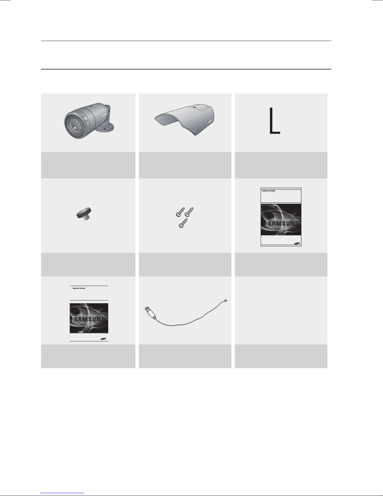
WHAT’S INCLUDED
Check if the following items are included in the product package.
ڮڞڪڈڍڎڒڋ
SCO-2370 Sunshield
L-type hexagon wrenches
(4.0mm)
High Resolution 37x
Weatherproof Camera
User Manual
Sunshield Adaptor (1EA) Tapping Screw (3EA) User Guide
High Resolution 37x
Weatherproof Camera
Quick Set-up Guide
SCO-2370
SCO-2370
Quick Set-up Guide Installation Video Output Cable
10_ introduction
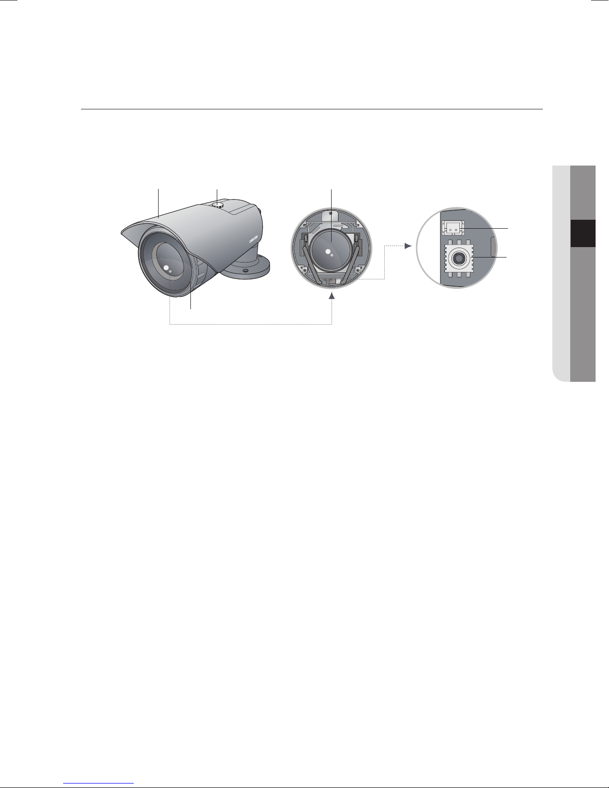
COMPONENT NAMES AND FUNCTIONS
Front
❶
➋
➌
● INTRODUCTION
➍
ڮڞڪڈڍڎڒڋ
➏
Camera Sunshield
➊
Sunshield adaptor : Fixing the sunshield onto the camera.
➋
Lens
➌
Video Output Terminal to Monitor : Used for monitoring of video output When
➍
camera installation.
Function Setup Switch : Display the menu on the screen and move the cursor
➎
to four directions to confirm status or after changing a
selected item.
➎
Front cover
➏
English_11

introduction
Back
❶
➋
➌
➍
Power input terminal : Connect the power as specified for each model here.
➊
MD Output Terminal : Motion detection signals are output through this terminal.
➋
RS-485 control terminal : You can control SETUP MENU through this port by using
➌
external controllers like a Remote controller that RS-485
Communication is supported. For details, see page 16.
Video output terminal : Video signals are output through this port. Connect this port
➍
to the Video IN port of a monitor.
M
Connector Signal Level
5±0.5sec
MD
There is no motion
0V
← →
USER Vcc
There is motion
I/O
Output
MD(Motion Detection) Output format is open collector.
12_ introduction
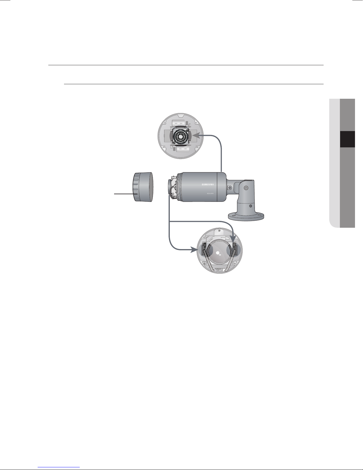
COMPONENT NAMES AND FUNCTIONS
Heater & Fan
This product is equipped with built-in heater & fan, and capable of maintaining
appropriate internal temperature as well as defrosting and dehumidification.
Fan
Front cover
Heater
● INTRODUCTION
While powered, the heater operates according to the camera’s internal temperature.
1.
(Note that the fan always operates if powered.)
y
While the camera is powered, the heater operates if its internal temperature drops below
0 °C. When the camera’s internal temperature reaches 10 °C, the heater stops operating.
y
Camera’s internal temperature is within -50°C ~ -10°C, the message “Low Temperature
Wait” appears on the black background. The camera initializes and outputs video signal
once it gets above -10°C.
Be careful not to touch the heater while installing if the ambient temperature is below than -10°C,
M
since the heater may operate immediately after applying the power.
If the front cover is cross threaded or not correctly tightened the camera housing will not be weatherproof.
When you combine the front cover, combine the triangle of front cover and triangle of main body
confront each other.
Frost can be found if the camera is left under -10°C and then powered, and the frost will be
removed automatically in about 3 hours.
The camera will be initialized if its internal temperature becomes 80°C or higher.
English_13
installation & connection
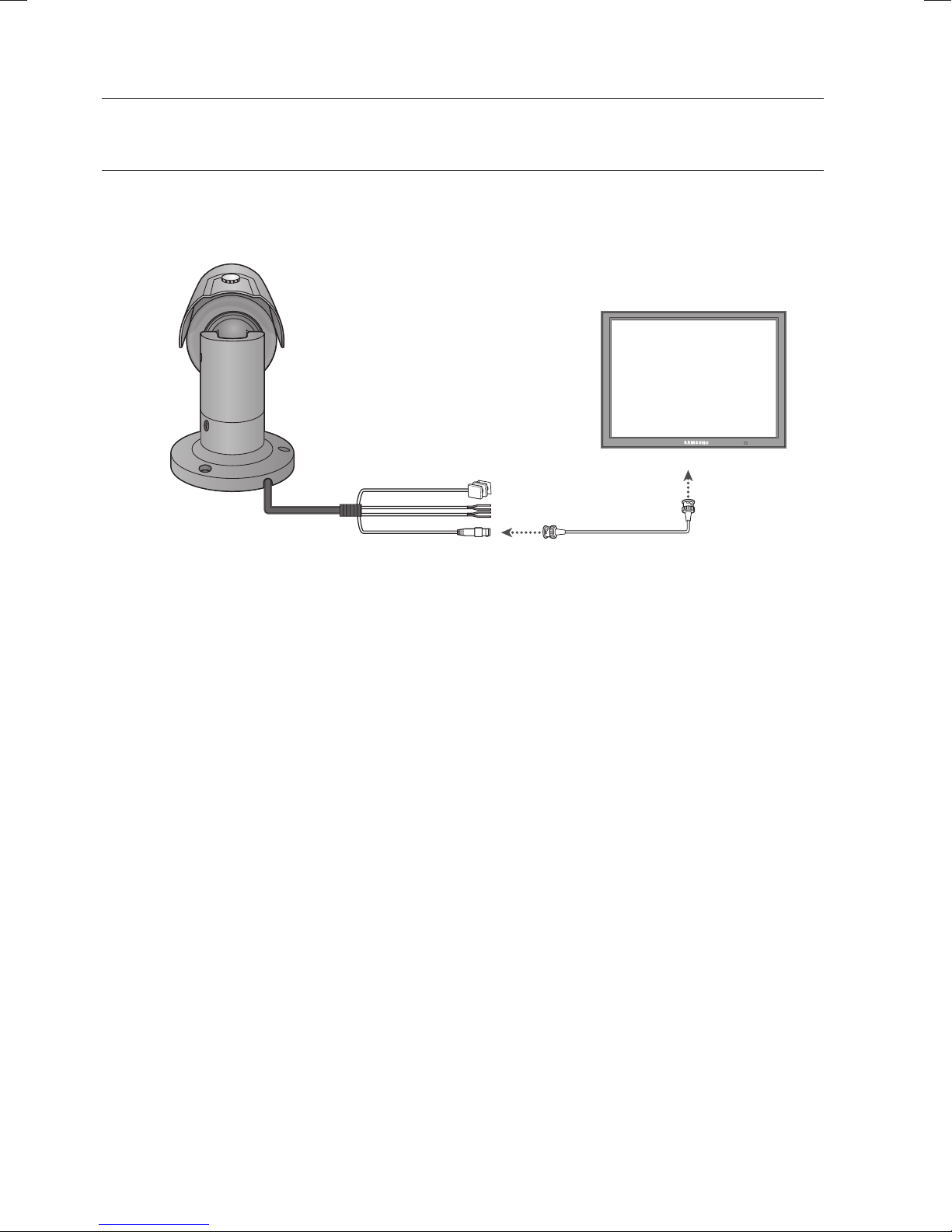
CONNECTING TO MONITOR
Please connect the video output terminal located on the back of the camera to the monitor.
Monitor
CCD Camera
y
The connection method varies depending on the type of monitor and accessories.Please
refer to the user’s manual for each instrument.
y
Please turn off the power when connecting.
14_ installation & connection

CONNECTING TO POWER
The recommended adaptor specification for SCO-2370N/P is AC 24V/1.5A over.
Please check the standard power requirement before connecting the power.
---- Power Input Terminal
● INSTALLATION & CONNECTION
When the resistance value of copper wire is at [20°C(68°F)]
Copper wire size(AWG)
Resistance value(Ω/m)
Voltage drop(V/m) 0.028 0.018 0.011 0.006
y
As shown in the table above, voltage decreases as the wire gets longer.
Therefore having an excessively long distance between the power adaptor and the
camera may affect the camera’s performance.
Â
Standard voltage for camera operation : DC 12V±10% / AC 24V±10%
Â
There may be some deviation in voltage drop depending on the type of wire and the
manufacturer.
Please use a power adaptor that meets the required standards.
#24(0.22mm²) #22(0.33mm2) #20(0.52mm2) #18(0.83mm2)
0.078 0.050 0.030 0.018
M
Please connect the power after installation.
English_15
installation & connection
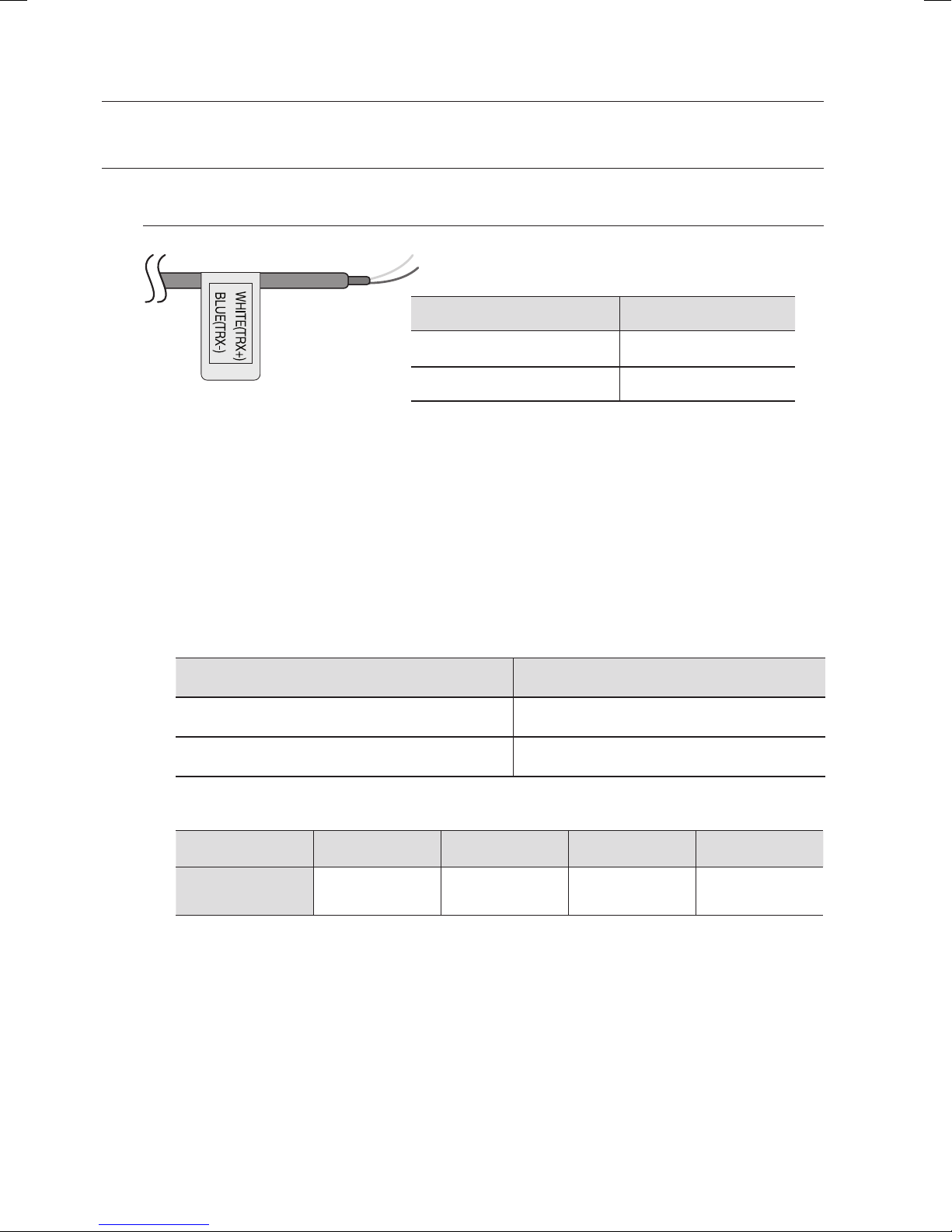
RS-485 COMMUNICATION CONTROL
Connecting to RS-485 Control Cable
CONTROL CABLE SPEC
WHITE RS-485+
BLUE RS-485-
Using RS-485 communication will enable you to control the OSD menu from a
SAMSUNG TECHWIN System Controller or DVR.
(1) Connection to a PC.
Connect the camera to the PC via a RS-485 converter using RS-485 and a serial cable.
EX)
SERIAL PORT OF THE PC(COM1) p SERIAL CABLE p RS-485 CONVERTER
RS-485 CONTROL CABLE
p
(2) Connection to a DVR or System Controller.
Connect the RS-485 cable to the connection ports of the DVR or System Controller.
485 Control Board Connection Port RS-485 Control Port
(+) CONNECTION TERMINAL WHITE (TRX+)
(-) CONNECTION TERMINAL BLUE (TRX-)
* RS-485 Communication establishment initial value
Item Camera ID BAUD RATE UART MODE RET PKT
Initial value 1 9600 8-NONE-1 DISABLE
When making a control system to control the camera, please use to the protocol(SAMSUNG-T,
M
SAMSUNG-E, PELCO-P, PELCO-D, VICON, PANASONIC, BOSCH, HONEYELL, AD).
When you connecting to RS-485 CONTROL TERMINAL, please peel off the outer skin inside the
RS-485 CONTROL TERMINAL.
16_ installation & connection
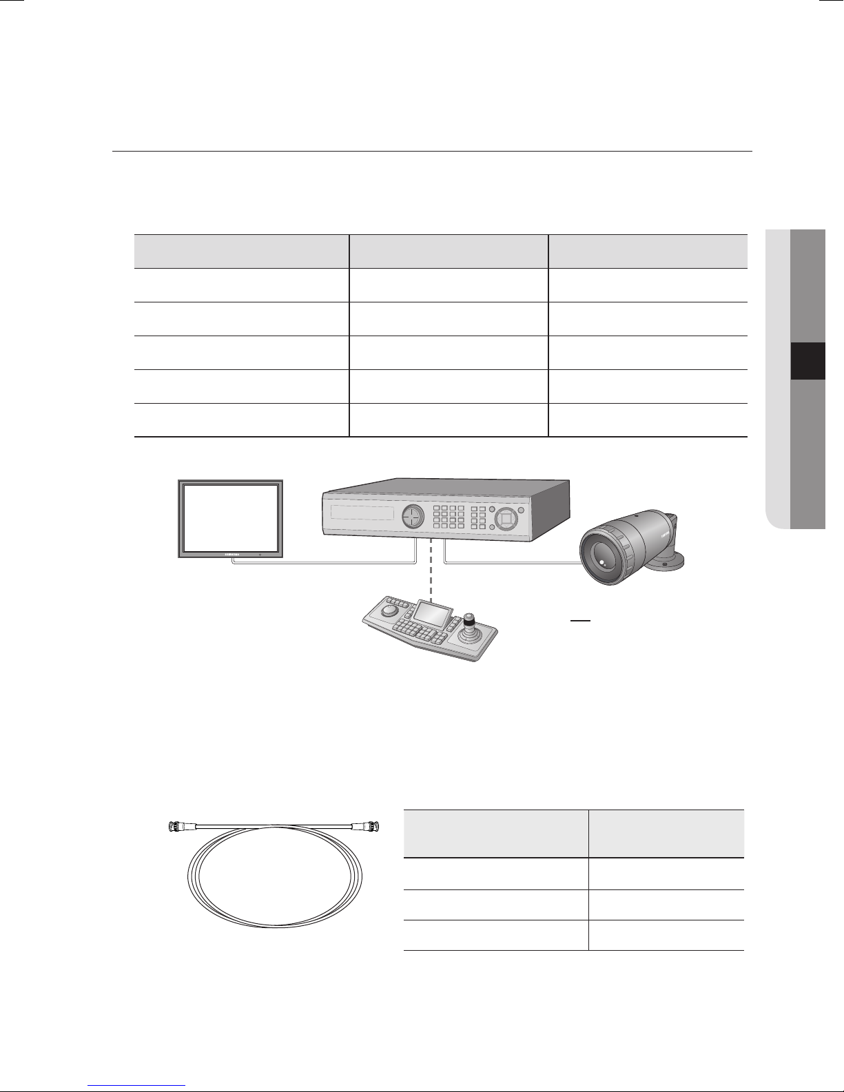
USING COAXIAL COMMUNICATIONS
y
Coaxial Communications System
y
OSD Control method
CAMERA DVR CONTROLLER
SET MENU/ENTER OSD KEY
UP UP KEY JOYSTICK UP
DOWN DOWN KEY JOYSTICK DOWN
LEFT LEFT KEY JOYSTICK LEFT
RIGHT RIGHT KEY JOYSTICK RIGHT
DVR
DVD
● INSTALLATION & CONNECTION
ڒڋ
ڈڍڎ
ڪ
ڮڞ
: BNC
•
---- : RS-485
•
- Video Cable
The camera’s video output port is connected to the monitor with a BNC coaxial
cable, shown below : If the distance between the camera and the monitor exceeds
the recommended maximum, please use an auxiliary video amp.
Distance
300m 3C2V(RG-59/U)
450m 5C2V(RG-6/U)
600m 7C2V(RG-11/U)
Recommended Cable
Specifi cation
If the camera is controlled through coaxial communication, please use a video amp intended for
M
coaxial communications. Regular video amps do not transfer coaxial signals.
English_17
 Loading...