

Page 1
Service Manual
1. Print / Copy speed
• SCX-8030ND : 30 ppm (A4)
• SCX-8040ND : 40 ppm (A4)
2. 800 MHz CPU
3. 250GB HDD
4. 512 MB Memory (Max. 1GB)
The keynote of Product
Digital Laser MFP
SCX-8030ND / 8040ND series
5. 8.9 inch color graphic touch-screen LCD
6. Various option units
• 3K Booklet fi nisher, 1K Standard fi nisher
DCF, HCF, Punch unit , Multi fax etc.
Page 2

GSPN (Global Service Partner Network)
Area Web Site
Europe,MENA, CIS,
Africa
E.Asia, W.Asia,
China, Japan
N.America,
S.America
https://gspn1.samsungcsportal.com
https://gspn2.samsungcsportal.com
https://gspn3.samsungcsportal.com
ⓒ
Samsung Electronics Co.,Ltd. August. 2010
Printed in Korea.
VERSION NO.
: 0.04
CODE
: 80x0-00000E
Page 3

chapter 1 Precautions
1.1 Safety Warning …………………………………………………… 1-1
1.2 Caution for safety ………………………………………………… 1-2
1.3 ESD Precautions ………………………………………………… 1-5
chapter 2 Product decription
2.1 Specifi cations …………………………………………………… 2-1
2.2 System confi guration …………………………………………… 2-7
2.3 Sensor location …………………………………………………… 2-16
Contents
2.4 Paper handling section ………………………………………… 2-20
2.4.1 Overview……………………………………………………… 2-20
2.4.2 Components ………………………………………………… 2-23
2.4.3 Functions …………………………………………………… 2-24
2.4.4 Paper tray …………………………………………………… 2-25
2.4.5 Pick up unit …………………………………………………… 2-26
2.4.6 Registration unit …………………………………………… 2-27
2.4.7 MPF unit ……………………………………………………… 2-28
2.5 Image formation ………………………………………………… 2-29
2.5.1 Printing process overview ………………………………… 2-29
2.5.2 Imaging unit ………………………………………………… 2-30
2.6 Fuser unit ………………………………………………………… 2-34
2.6.1 Fuser unit overview ………………………………………… 2-34
2.6.2 Fuser unit components ……………………………………… 2-35
2.6.3 Fuser unit drive ……………………………………………… 2-36
2.6.4 Temperature control ………………………………………… 2-37
2.7 Laser scanning unit ……………………………………………… 2-38
2.7.1 Laser scanning unit overview ……………………………… 2-38
2.7.2 Laser scanning optical path ………………………………… 2-39
2.7.3 Laser synchronizing detectors …………………………… 2-40
2.8 Printer Drive system ……………………………………………… 2-41
Page 4

Contents
2.8.1 Drive Motors ………………………………………………… 2-41
2.8.2 Main drive unit (OPC, DEVE, MP, REGI, DUPLEX) …… 2-43
2.8.3 Pick-up Drive ………………………………………………… 2-44
2.8.4 Fuser /Exit Drive …………………………………………… 2-45
2.8.5 Toner Duct Drive …………………………………………… 2-46
2.8.6 Drive of Toner Supply ……………………………………… 2-46
2.8.7 WTB leveling drive ………………………………………… 2-46
2.8.8 PR Release drive …………………………………………… 2-47
2.9 Scanner system ………………………………………………… 2-48
2.9.1 Scannner system overview ………………………………… 2-48
2.9.2 Scanning System components …………………………… 2-49
2.10 DADF system …………………………………………………… 2-51
2.10.1 DADF systme overview …………………………………… 2-51
2.10.2 Electric parts layout ………………………………………… 2-52
2.10.3 Description of drive system operations …………………… 2-53
2.11 Printer Electronics confi guration ……………………………… 2-59
2.11.1 Video controller …………………………………………… 2-62
2.11.2 OPE controller …………………………………………… 2-70
2.11.3 Engine controller ………………………………………… 2-74
2.11.4 Scan controller …………………………………………… 2-77
2.11.5 DADF controller …………………………………………… 2-78
2.11.6 Interface part ……………………………………………… 2-79
2.11.7 Connection part …………………………………………… 2-79
2.11.8 SMPS board ……………………………………………… 2-80
2.11.9 HVPS board ……………………………………………… 2-82
2.11.10 Eraser PBA ……………………………………………… 2-83
2.11.11 DC Power PBA …………………………………………… 2-83
2.11.12 Cassette Joint PBA ……………………………………… 2-84
2.11.13 Side Joint PBA …………………………………………… 2-84
2.11.14 Toner Connector PBA …………………………………… 2-85
2.11.15 CRUM PBA ……………………………………………… 2-86
2.11.16 Development Crum Interface PBA ……………………… 2-86
2.11.17 Deve Crum Joint PBA …………………………………… 2-87
2.11.18 Toner Curm Joint PBA …………………………………… 2-87
Page 5

Contents
2.11.19 Fuser PBA ………………………………………………… 2-87
2.11.20 Waste Sensor PBA ……………………………………… 2-88
2.11.21 LED Panel PBA …………………………………………… 2-88
2.11.22 Scan Joint PBA …………………………………………… 2-89
2.11.23 CCDM PBA ……………………………………………… 2-90
2.11.24 Scan Cover Open Sensor PBA ………………………… 2-91
2.11.25 DADF Length Sensor PBA ……………………………… 2-91
2.11.26 DADF Width Sensor PBA ……………………………… 2-92
2.11.27 DADF Mixed Sensor PBA ……………………………… 2-92
2.11.28 DADF LED Panel PBA …………………………………… 2-93
2.11.29 Exit LED Panel PBA ……………………………………… 2-93
2.12 Heating cables ………………………………………………… 2-94
chapter 3 Replacement procedure
3.1 General Disassembly Procedure Precautions ………………… 3-1
3.2 Cover ……………………………………………………………… 3-2
3.2.1 Front cover …………………………………………………… 3-2
3.2.2 Left cover …………………………………………………… 3-3
3.2.3 Rear cover …………………………………………………… 3-3
3.2.4 Right cover …………………………………………………… 3-4
3.3 OPE unit …………………………………………………………… 3-5
3.4 Scan unit ………………………………………………………… 3-10
3.4.1 Scan glass …………………………………………………… 3-11
3.4.2 Scan main PBA ……………………………………………… 3-12
3.4.3 Lamp ………………………………………………………… 3-13
3.4.4 Original size detection sensor ……………………………… 3-15
3.4.5 Joint PBA …………………………………………………… 3-15
3.4.6 Joint sub PBA ……………………………………………… 3-16
3.4.7 Fan …………………………………………………………… 3-16
3.4.8 Pulley-belt …………………………………………………… 3-17
3.4.9 Scan motor and gear belt ………………………………… 3-18
Page 6

Contents
3.4.10 Home sensor ……………………………………………… 3-18
3.4.11 Scanner heating cable …………………………………… 3-19
3.4.12 Align set …………………………………………………… 3-23
3.5 Fuser unit ………………………………………………………… 3-24
3.6 Side Unit …………………………………………………………… 3-35
3.6.1 Duplex sensors ……………………………………………… 3-36
3.7.2 Transfer sensors …………………………………………… 3-37
3.7.3 MP unit ……………………………………………………… 3-39
3.7 Electrical components …………………………………………… 3-44
3.7.1 Engine controller …………………………………………… 3-44
3.7.2 Hard Disk Drive (HDD) ……………………………………… 3-45
3.7.3 Video controller ……………………………………………… 3-46
3.7.4 Joint PBA …………………………………………………… 3-47
3.7.5 Toner PBA …………………………………………………… 3-47
3.7.6 Toner motor ………………………………………………… 3-48
3.7.7 DC power PBA ……………………………………………… 3-49
3.7.8 HVPS PBA …………………………………………………… 3-50
3.7.9 Lift motor …………………………………………………… 3-51
3.7.10 SMPS PBA ………………………………………………… 3-52
3.7.11 SMPS FAN ………………………………………………… 3-53
3.7.12 Ozone Filter FAN ………………………………………… 3-55
3.7.13 Side joint PBA ……………………………………………… 3-56
3.7.14 Eraser Lamp ……………………………………………… 3-57
3.7.15 Waste sensor PBA ………………………………………… 3-58
3.7.16 Temperature sensor ……………………………………… 3-58
3.8 Main drive unit …………………………………………………… 3-60
3.8.1 Main drive motor …………………………………………… 3-62
3.8.2 Main drive clutch …………………………………………… 3-62
3.9 Exit drive unit …………………………………………………… 3-63
3.10 Toner Duct drive unit …………………………………………… 3-65
3.11 PR Release drive unit ………………………………………… 3-66
3.12 Pick-up drive unit ………………………………………………… 3-67
3.13 WTB leveling drive unit ………………………………………… 3-68
3.14 LSU (Laser Scanning Unit) …………………………………… 3-71
Page 7

Contents
3.15 Frame Duct …………………………………………………… 3-74
3.16 DADF Unit ……………………………………………………… 3-75
3.16.1 Width / Length sensor PBA ……………………………… 3-84
3.16.2 DADF Main PBA …………………………………………… 3-85
3.16.3 DADF Motors ……………………………………………… 3-87
3.16.4 DADF cover open sensor ………………………………… 3-90
3.16.5 Pick-Up Guide Sensor PBA ……………………………… 3-91
3.16.6 DADF Solenoid …………………………………………… 3-93
3.17 Exit Unit ………………………………………………………… 3-94
3.18 Regi. Unit ……………………………………………………… 3-96
3.19 Pick-Up Unit …………………………………………………… 3-98
3.20 Cassette Heating Cable ……………………………………… 3-100
chapter 4 Troubleshooting
4.1 Entering/Exiting Diagnostics Mode ……………………………… 4-1
4.2 Serive mode menu tree …………………………………………… 4-2
4.2.1 Information tab ……………………………………………… 4-2
4.2.2 Maintenance counts tab …………………………………… 4-4
4.2.3 Diagnostics tab …………………………………………… 4-5
4.2.4 Service Functions ………………………………………… 4-5
4.3 Information ………………………………………………………… 4-6
4.3.1 General ……………………………………………………… 4-6
4.3.2 Supply status ……………………………………………… 4-6
4.3.3 Software version …………………………………………… 4-8
4.3.4 Service Hours ……………………………………………… 4-8
4.3.5 Fault Log …………………………………………………… 4-8
4.3.5 Print reports ………………………………………………… 4-8
4.4 Maintenance Counts …………………………………………… 4-9
4.4.1 Fault count ………………………………………………… 4-9
4.4.2 Jam count …………………………………………………… 4-10
4.4.3 Part replacement count …………………………………… 4-12
4.5 Diagnotics ………………………………………………………… 4-13
Page 8

Contents
4.5.1 Engine diagnostics ………………………………………… 4-13
4.5.1.1 NVM Read/Write ……………………………………… 4-13
4.5.1.2 Engine Test Routines ………………………………… 4-13
4.5.2 Fax diagnostics …………………………………………… 4-14
4.5.2.1 Fax NVM Read/Write ………………………………… 4-14
4.5.2.2 Fax Test Routines ……………………………………… 4-15
4.5.3 Scanner diagnostics ……………………………………… 4-17
4.5.3.1 Shading Test ………………………………………… 4-17
4.5.3.2 Scanner/DADF NVM Read/Write …………………… 4-17
4.5.3.3 Scanner/DADF Test Routines ……………………… 4-18
4.5.4 Adjustment ………………………………………………… 4-20
4.5.4.1 Print Adjustment ……………………………………… 4-20
4.5.4.2 Copy Adjustment ……………………………………… 4-22
4.5.4.3 Scan Area Adjustment ………………………………… 4-23
4.5.4.4 DADF Adjustment ……………………………………… 4-25
4.5.4.5 Finisher Adjustment …………………………………… 4-27
4.5.5 ACS ………………………………………………………… 4-30
4.5.6 Color Management ………………………………………… 4-31
4.6 Sevice functions ………………………………………………… 4-32
4.6.1 Main Memory Clear ………………………………………… 4-32
4.6.2 Hard Disk Maintenance …………………………………… 4-32
4.6.3 Debug Log …………………………………………………… 4-32
4.6.4 Port …………………………………………………………… 4-33
4.6.5 Capture Log ………………………………………………… 4-33
4.6.6 Toner Save ………………………………………………… 4-33
4.6.7 Count Setting of Large Page ……………………………… 4-33
4.6.8 System Recovery …………………………………………… 4-33
4.6.9 User Data Management …………………………………… 4-34
4.6.10 TR Control Mode ………………………………………… 4-35
chapter 5 Updating Firmware
5.1 Updating from the Printer Control Panel ……………………… 5-2
5.2 Updating from the Network …………………………………… 5-8
Page 9

chapter 6 Preventive Maintenance (PM)
6.1 PM Supplies ……………………………………………………… 6-1
6.2. PM Procedures ………………………………………………… 6-5
6.2.1 Toner cartridge ……………………………………………… 6-5
6.2.2 Imaging unit ………………………………………………… 6-7
6.2.3 2nd Transfer roller ………………………………………… 6-11
6.2.4 Fuser Unit …………………………………………………… 6-12
6.2.5 Pick up/ Retard/ Forward roller …………………………… 6-13
6.2.6 Ozone Filter ………………………………………………… 6-13
6.2.7 DADF Rollers (Pick up /ADF/ Retard) …………………… 6-14
6.2.8 MP Pick up / Retard / Forward roller …………………… 6-19
6.2.9 Scanner Fan Filter ………………………………………… 6-21
Contents
6.3. Cleaning the PM parts ………………………………………… 6-22
6.3.1 Cleaning the charge scorotron …………………………… 6-22
6.3.2 Cleaning the pick up roller ………………………………… 6-22
6.3.3 Cleaning the Regi roller …………………………………… 6-23
6.3.4 Cleaning the tray1 feed roller ……………………………… 6-23
6.3.5 Cleaning the tray2 feed roller ……………………………… 6-24
6.3.6 Cleaning the DADF retard rubber pad …………………… 6-25
6.3.7 Cleaning the DADF rollers ………………………………… 6-26
6.3.7 Cleaning the ADF glass …………………………………… 6-27
chapter 7 Troubleshooting
7.1 Procedure of checking the symptoms ………………………… 7-1
7.2 Error code and troubleshooting ………………………………… 7-3
7.2.1 Error code and error message …………………………… 7-3
7.2.2 Error Code Details ………………………………………… 7-11
7.3 Image quality problems and solutions ………………………… 7-101
7.3.1 Vertical Lines ………………………………………………… 7-102
7.3.2 Horizontal Lines ……………………………………………… 7-103
7.3.3 White spot …………………………………………………… 7-104
7.3.4 Black background ………………………………………… 7-105
7.3.5 Blurred image ……………………………………………… 7-106
Page 10

7.3.6 Uneven pitch and jitter image ……………………………… 7-107
7.3.7 Skewed image ……………………………………………… 7-108
7.3.8 Low image density ………………………………………… 7-109
7.3.9 Blank copy, Black copys …………………………………… 7-110
7.3.10 Uneven density in sub scan direction …………………… 7-112
7.3.11 Uneven density in main scan direction ………………… 7-113
7.3.12 Poor fusing performance ………………………………… 7-114
7.3.13 Stain on the paper back side …………………………… 7-115
7.3.14 DADF skew testing ……………………………………… 7-116
7.4 Other Errors ……………………………………………………… 7-121
chapter 8 System Diagram
Contents
8.1 Engine 1 …………………………………………………………… 8-1
8.2 Engine 2 …………………………………………………………… 8-2
8.3 Main board & OPE ……………………………………………… 8-3
8.4 Scan & DADF …………………………………………………… 8-4
8.5 Bottle joint board & side joint board …………………………… 8-5
8.6 DC control board ………………………………………………… 8-6
8.7 Cassette joint board & Drive joint board ……………………… 8-7
8.8 Heater & Fuse …………………………………………………… 8-8
chapter 9 System Recovery
9.1 Entry Point ………………………………………………………… 9-1
9.2 USB ………………………………………………………………… 9-2
9.3 Network …………………………………………………………… 9-4
9.4 Confi rmation Page ……………………………………………… 9-5
9.5 Error Page ………………………………………………………… 9-6
9.6 Progress Page …………………………………………………… 9-7
9.7 Error List …………………………………………………………… 9-8
9.8 HDD Repair ……………………………………………………… 9-8
9.9 HDD Failure ……………………………………………………… 9-10
Page 11

Contents
chapter 10
Reference Information
10.1 Tools for troubleshooting ……………………………………… 10-1
10.2 Abbreviations …………………………………………………… 10-4
Page 12
1. Prec
a
n
o
(2) Use only Samsung replacement parts
t
e
s
f
IEC 825. Cl
n
t
o
-
o
utions
1. Warning and cautio
In order to prevent accidents and to prevent damage t
below carefully before servicing the printer and follow
1.1 Safety Warning
(1) Only to be serviced by appropriately qualified servi
High voltages and lasers inside this product are da
qualified service technician.
.
There are no user serviceable parts inside the prin
additions to the printer as these could cause the pr
fire hazards.
(3) Laser Safety Statement
The Printer is certified in the U.S. to conform to th
Subchapter J for Class 1(1) laser products, and el
orming to the requirements of
laser system and printer are designed so there is n
Class I level during normal operation, user mainte
ass I las
for s afety
the equipment please read the precautions listed
them closely.
ce technician.
ngerous. This printer should only be serviced by a
er. Do not make any unauthorized changes or
inter to malfunction and create an electric shock or
requirements of DHHS 21 CFR, chap ter 1
ewhere, it is certified as a Class I laser product coner products are not considered to be hazardous. The
ever any human access to laser radiation above a
ance, or prescribed service condition.
Warning >> Never operate or service the printer with
assembly. The reflected beam, although invisible, can
When using this product, these basic safety pre-cauti
electric shock, and personal injury.
he protective cover removed from Laser Scanner
damage your eyes.
ns should always be followed to reduce risk of fire,
Service Manual
SCX-8030/8040 series
1
1
SAMSUNG ELECTRONICS
Version 0.05
Page 13

a
1.2 Caution for safety
i
o
e
w
w
u
p
e
d
(2)
() y p pp p
o
(5)
a
() p g p
f
c
t
c
r
a
cable immediately, do not reuse or repair the dama
a
m
o
p
i
p
c
d
w
e
h
-
t
y sp
yp
cable. Some chemicals can attack the coating on
1.2.1 Toxic material
1. Prec
utions
This product contains toxic materials that could cause
(1) If the LCD control panel is damaged it is possible f
with the skin should be avoided. Wash any splash
doctor. If the liquid gets into the mouth or is swallo
(2) Please keep Drum cartridge and Toner cartridge a
Drum cartridge and Toner Cartridge may be harmf
1.2.2 Electric shock and fire safety
Failure to follow the following instructions could cause
(1) Use only the correct voltage, failure to do so could
electric shock.
Use only the power cable supplied with the printer.
cable to overheat and potentially cause a fire.
(3) Do not overload the power socket, this could lead t
lead to a fire.
(4) Do not allow water or other liquids to spill into the p
paper clips, pins or other foreign objects to fall into
to an electric shock or fire hazard.
Never touch the plugs on either end of the power c
When servicing the printer remove the power plug
(6) Use caution when inserting or removing the power
firmly and pull. The power connector must be inser
overheating possibly leading to a fire.
(7) Take care of the power cable. Do not allow it to be
damaged. Do not place objects on top of the powe
overheat and cause a fire. Exposed cables could c
the power cable, weakening the cover or exposing
(8) Ensure that the power sockets and plugs are not cr
should be repaired immediately. Take care not to c
the machine.
(9) Use caution during thunder or lightning storms. Sa
from the power source when such weather conditi
ower cord if it is still connected to the wall socket
(10) Avoid damp or dusty areas, install the printer in a
machine near a humidifier or in front of an air con
can lead to overheating and cause a fire or cause
(11) Do not position the printer in direct sunlight. This
possibly leading to the printer failing to work prop
(12) Do not insert any metal objects into the machine t
could make contact with a high voltage conductor
llness if ingested.
r the liquid inside to leak. This liquid is toxic. Contac
s from eyes or skin immediately and contact your
ed see a doctor immediately.
ay from children. The toner powder contained in the
l and if swallowed you should contact a doctor.
recautions
lectric shock or potentially cause a fire.
amage the printer and potentially cause a fire or
Use of an incorrectl
overheating of the cables inside the wall and could
rinter, this can cause electric shock. Do not allow
the printer these could cause a short circuit leading
ble with wet hands, this can cause electric shock.
rom the wall socket.
onnector. When removing the power connector, grip it
ed completely, otherwise a poor contact could cause
ome twisted, bent sharply around corners or wise
cable. If the power cable is damaged it could
use an electric shock. Replace the damaged power
cables causing fire and shock risks.
cked or broken in any way. Any such defects
ut or damage the power cable or plugs when moving
sung recommends that this machine be disconnected
ns are expected. Do not touch the machine or the
n these weather conditions.
lean well ventilated location. Do not position the
itioner. Moisture and dust built up inside the machine
parts to rust.
ill cause the temperature inside the printer to rise
rly and in extreme conditions could lead to a fire.
rough the ventilator fan or other part of the casing, it
inside the machine and cause an electric shock.
ecified cable could cause the
Service Manual
SCX-8030/8040 series
1
2
SAMSUNG ELECTRONICS
Version 0.05
Page 14

a
1.2.3 Handling Precautions
a
(1) Ensure the printer is installed on a level surface, ca
v
o
u
o
o
u
g
o
t
g
(3) Disconnect printer interface cables and power cabl
u
x
-
The OPC Drum can be irreparably damaged if it e
d
c
o
g
)
C
t
-
supporting its weight. Failure to do so could
p
light
1. Prec
utions
The following instructions are for your own personal s
product.
cause the printer to tip or fall.
(2) The printer contains many rollers, gears and fans.
fingers, hair or clothing in any of these rotating de
(3) Do not place any small metal objects, containers
which if spilled could get into the machine and ca
(4) Do not install the machine in areas with high dust
a humidifier or heater. Damage could be caused t
(5) Do not place candles, burning cigarettes, etc on th
(6) When reinstalling the imaging unit or ITB unit at p
1.2.4 Assembly / Disassembly Preca
Replace parts carefully and always use Samsung par
cable routing before dismantling any part of the machi
Please carry out the following procedures before dism
(1) Check the contents of the machine memory and m
if the main board or network card is replaced.
(2) Ensure that power is disconnected before servicin
(4) Only use approved spare parts. Ensure that part n
temperature rating are correct.
(5) When removing or re-fitting any parts do not use e
plastic.
(6) Take care not to drop any small parts into the mac
(7) Handling of the OPC Drum
Take care not to expose the OPC Drum either to
room lighting. Exposure for as little as 5 minutes
properties and will result in print quality degradati
Remove the OPC Drum and store it in a black ba
working with the Covers (especially the top cover
damage the OPC Drum.
- Take care not to scratch the green surface of OP
If the green surface of the Drum Cartridge is scra
compromised.
fety, to avoid injury and so as not to damage the
of
Take great care to ensure that you do not catch your
ices.
f water, chemicals or other liquids close to the printer
se damage, shock or fire hazard.
r moisture levels, beside on open window or close to
the printer in such areas.
e printer, These could cause a fire.
wer off, perform the OPC-ACR surely.
tions
s. Take care to note the exact location of parts and
ne. Ensure all parts and cables are replaced correctly.
antling the printer or replacing any parts.
ake a note of any user settings. These will be erased
or replacing any electrical parts.
.
mber, product name, voltage, current and
cessive force, especially when fitting screws into
hine.
to
irect sunlight or to fluorescent or incandescent
an damage the surface of the photoconductive
n. Take extra care when servicing the printer.
or other lightproof container. Take care when
open as light is admitted to the OPC area and can
Drum Unit.
ched or touched the print quality will be
.
Service Manual
SCX-8030/8040 series
1-1
3
3
SAMSUNG ELECTRONICS
Version 0.05
Page 15

1. Prec
a
u
r
o
w
v
quip
qp
e
h
s
o
-
e
utions
1.2.5 Disregarding this warning may
(1) Be careful with high temperature compone nts.
The fuser unit works at a high temperature. Use ca
cool down before disassembly.
(2) Do not put fingers or hair into the rotating parts.
When operating a printer, keep your hands and hai
motor, fan, etc.).
(3) When moving the printer :
- When transporting/installing the equipment, employ f
- Be sure not to hold the movable parts or units (e.g. th
equipment.
- Be sure to use a dedicated outlet with 110V/220V po
- The equipment must be grounded for safety.
- Select a suitable place for installation. Avoid excessi
sunlight.
- Provide proper ventilation since the equipment emits
- The e
-Be sure to fix and plug in the power cable securely aft
-If you are moving the machine a short distance, you s
(e.g : same building through elevator)
- If you are moving the machine a long distance, you
& staple unit, tape and disassemble all trays. (e.g : m
ment must be installed near the socket outl
cause bodily injury
tion when working on the printer. Wait for the fuser to
away form the rotating parts (Paper feeding entrance,
ur people and be sure to hold the lifting handles.
e control panel, DADF) when transporting the
er input.
e heat, high humidity, dust, vibration and direct
a slight amount of ozone.
et and must be accessible.
r the installation so that no one trips over it.
ould separate the finisher.
hould remove toner & imaging unit, lock scan carrier
ved by truck or so)
1
Service Manual
SCX-8030/8040 series
4
SAMSUNG ELECTRONICS
Version 0.05
Page 16

a
1.3 ESD Precautions
d
integrated circuits, some field effect transistors, and se
h
p
n
o
h
m
d
4. Use only an anti
static solder removal device. Som
y
v
s
g
E
d
n
electricity sufficient to damage an ESD
-
chip components
solder removal devices not classified as anti
v
s
1. Prec
utions
Certain semiconductor devices can be easily damage
commonly called “Electrostatically Sensitive (ES) Dev
The techniques outlined below should be followed to
caused by static electricity.
Caution >>Be sure no power is applied to the chassis
1. Immediately before handling a semiconductor com
off any electrostatic charge on your body by touchi
commercially available wrist strap device, which sh
prior to applying power to the unit under test.
2. After removing an electrical assembly equipped wit
such as aluminum or copper foil, or conductive foa
vicinity of the assembly.
3. Use only a grounded tip soldering iron to solder or
“
”
-
static” can generate electrical charges sufficient to
5. Do not use Freon-propelled chemicals. When spra
damage ESDs.
6. Do not remove a replacement ESD from its protecti
Most replacement ESDs are packaged with all lead
or a comparable conductive material.
by static electricity. Such components are
ices” or ESDs. Examples of typical ESDs are:
“”
.
elp reduce the incidence of component damag e
or circuit, and observe all other safety precautions.
onent or semiconductor-equipped assembly, drain
g a known earth ground. Alternatively, employ a
uld be removed for your personal safety reasons
ESDs, place the assembly on a conductive surface ,
, to prevent electrostatic charge buildup in the
esolder ESDs.
“
-
damage ESDs.
ed, these can generate electrical charges sufficient to
e packaging until immediately before installing it.
shorted together by conductive foam, aluminum foil,
7. Immediately before removing the protective shortin
touch the protective material to the chassis or circui
8. Maintain continuous electrical contact between the
until completely plugged or soldered into the circuit.
9. Minimize bodily motions when handling unpackage
the brushing together of clothing fabric and lifting o
.
material from the leads of a replacement ESD,
t assembly into which the device will be installed.
SD and the assembly into which it will be installed,
replacement ESDs. Normal motions, such as
e’s foot from a carpeted floor, can generate static
Service Manual
SCX-8030/8040 series
1
5
SAMSUNG ELECTRONICS
Version 0.05
Page 17

2. Product
D
0
6
0
)
B
B
m
e
L
W
H
H
-
h
2. Product description
2.1 Specifications
General Specifications
escription
Item SCX-8030ND
Printing Speed (A4) 30 ppm
FCOT < 7 sec
Warm-up Time < 25 sec
Duplex Printing Speed 30 ppm
Scanning Speed (A4) (Color)
Memory 512MB (Max.1GB )
HDD 250GB
CPU SPGPv4 800MHz
Resolution
Gradation 256
Size (W x D x H ) 677.5 x 742.8 x 924 m
Weight Approx. 113Kg (250lb
40 ipm @ 600 dpi
60 ipm @ 300 dpi
• Optical : 600 x 600 d
• Enhanced : Draft 60
Default
Up to 6
SCX-8040ND
40 ppm
< 5.5 sec
40 ppm
pi
x 600 x 1bit
00 x 600 x 2 bit
0 x 600 x 4 bit
m (26.7 x 29.2 x 36.4 inches)
(Including consumables and tray)
Noise (dB)
Power consumption
Power requirement
Power output rating for heating
wire in DCF/HCF
Service Manual
SCX-8030/8040 series
• Ready mode : 37 d
• Printing mode : 54 d
• Copying mode : 57 d
• Average operating
• Ready mode : Less t
• Low Power mode : L
• Power Save mode :
• Power off mode : 0
AC 110-127V , 50/60
Note - See the Rating
(hertz) and type of cur
AC 110-127V , 50/60
Note - See the Rating
and type of current.
The voltage rating of
(A)
(A)
B(A)
ode : Less than 1,100 W
han 250 W
ss than 40 W
ess than 7 W
z or AC 220-240V , 50/60 Hz
label on the machine for the correct voltage, frequency
rent.
z or AC 220-240V , 50/60 Hz
label on the machine for correct voltage, frequency (hertz)
eating wire is the same as the machine’s voltage rating.
2
1
SAMSUNG ELECTRONICS
Version 0.05
Page 18
D
Printer Specifications
Printing method
laser beam printing
L
400
600
p
5
e
Duplex copy speed
Dupl
2)
0
Zoom range
4
-
t(600x600x2 dpi)
Dupl
2)
2. Product
escription
Item SCX-8030ND
Printing speed Up to 30 ppm (A4), 30 ppm
Duplex printing speed Up to 30 ipm (A4), 30 ipm (
First print out time
(from ready)
Print resolution
Printer language PCL5e, PCL6, PostScript 3,
OS compatibility
Interface
< 9 sec
•Default : Up to 2,
• Max : Up to 9,600 x 600 d
• Windows: 2000 ,XP,2003 ,
• Various Linux OS
• Macintosh: Mac OS X 10.
• High speed USB 2.0
• Ethernet 10/100/1000 Bas
• FDI (optional)
x
Copier specifications
SCX-8040ND
(Letter) Up to 40 ppm (A4), 40 ppm (Letter)
etter) Up to 40 ipm (A4), 40 ipm (Letter)
< 8 sec
dpi effective outpu
i effective output(600x600x2 dpi)
PDF 1.7+, TIFF, PJL
Vista ,2008 ,Win7
~10.6
TX (embedded type)
Item SCX-8030ND
Copy Speed Up to 30 cpm (A4), 30 cpm
Simplex to Duplex (1-1,1-2)
First copy out time < 7 sec
Copy resolution
Service Manual
SCX-8030/8040 series
: Up to 30 ipm in A4 (30 ipm
ex to Duplex (2-1.2-
: Up to 18 ipm in A4 (18 ipm
• Platen : 600 x 600 dpi
• Document feeder: Up to 6
• Platen : 25% to 400%
• Document feeder: 25% to
SCX-8040ND
(Letter) Up to 40 cpm (A4), 40 cpm (Letter)
Simplex to Duplex (1-1,1-2)
in Letter)
in Letter)
0 x 600 dpi
00%
2
2
: Up to 40 ipm in A4 (40 ipm in Letter)
ex to Duplex (2-1.2-
: Up to 24 ipm in A4 (24 ipm in Letter)
< 5.5 sec
SAMSUNG ELECTRONICS
Version 0.05
Page 19
D
0
t
Scanner specifications
0
8
Internal: 3
n
0
3
Applicable line
Public Sw
M
e
(
• Standar
0
F
n
c
-
bit
Telephone Network (PSTN) or behind PABX
203 x 98 dpi
2. Product
escription
Item SCX-803
Compatibility TWAIN s
Scanning method Color CC
TWAIN standard
Resolution
Network Scan File format PDF, TIF
Effective scanning length Max. 432
Effective scanning width Max. 297
Color bit depth
Mono bit depth
Scan to USB 100, 200,
Scan to Email 100, 200,
Scan to Server 100, 200,
Up to 60
(Up to 4,
External:
1 bit for li
8 bit for g
ND SCX-8040ND
andard (network)
D
x 600 dpi
00 x 4,800 dpi by software enhancement)
300, 400, 600 dpi
300, 400, 600 dpi
300, 400, 600 dpi
F, JPEG
mm (17 inches)
mm (11.7 inches)
24 bit
eart & halftone
ray scale
Fax Specifications
Item SCX-803
Compatibility Super G
Data coding MH/MR/
Modem speed 33.6kbps
Transmission speed Up to 3 s
Maximum document length 432 mm
Resolution
Memory HDD Ba
Auto dialer up to 500
Service Manual
SCX-8030/8040 series
• Fine : 2
• Super
• Ultra Fi
ND SCX-8040ND
MR/JBIG/JPEG
conds/page
17 inches)
:
3 x 196 dpi
ine : 300 x 300 dpi
e : 600 x 600 dpi
kup
numbers
2
3
SAMSUNG ELECTRONICS
Version 0.05
Page 20
D
Paper Specifications
e
e
o
m
3
4
C
Plain Pap
Th
e
p
h
e
aPre
1
X
0
g
g
a
a
D
a
-
r
Thick Pap
2. Product
escription
Item SCX-8030ND
• Standard : 1,040 (Cassett
Input Paper Capacity
Output Paper Capacity
Paper Size
Paper Type
Paper Weight
• Maximum : 1,040 (Cassett
Note – The SCX-8025ND n
• Standard : 500 (Center Ou
• Maximum : 3,250 (Booklet
• Cassette :
•MP Tray :
• High Capacity Feeder :
assette :
•
• MP Tray :
• High Capacity Feeder :
• Cassette : 60 ~ 163 gsm (
• MP Tray : 60 ~ 216 gsm (1
• High Capacity Feeder : 60
148 x 210 m
98 x 148 mm(
A
er,
Recycled, Lett
Plain Pa
Recycled, Lett
Transparency,
er, T
Pl
SCX-8040ND
1 & 2) + 100 (MP Tray)
1 & 2) + 2,000 (High Capacity Feeder) + 100 (MP Tray)
t supports the Tray(DCF,HCF) and the Finishe
tput Tray)
Finisher) + 125 (Job Separator)
(5.83”x 8.27”) ~ 305 x 457 mm (12”x 18”)
.8”x 5.8”) ~ 305 x 1200 mm (12”47”)
/ Letter
n Paper,
rhead, Cotton, Colored, Archive, CardStock, Label
in Paper, Thick Paper, Bond, Punched, Pre-Printed,
rhead, Cotton, Colored, Archive, CardStock, Label,
Envelope
in Paper, Thin Paper, Thick Paper, Bond, Punched,
-Printed, Recycled, Cotton, Colored, CardStock
6lb Bond ~ 90lb Index)
6lb Bond ~ 90lb Cover)
~ 163 gsm (16lb Bond ~ 90lb Index)
er, Bond, Punched, Pre-Printed,
Original Capacity for DADF 100 sheets
Original Size for DADF
Original Weight for DADF
• Full supported Size : 140
• Auto-detected Size : A3, B
• Simplex : 42 ~ 163 gsm (3
• Duplex : 50 ~ 128 gsm (30
Consumables
Product Model name Life **
Toner Cartridge
Imaging unit MLT-R607K 100K p
Waste Toner Container MLT-W606 300K p
* American 35K Toner can be used for SCX-8030N
** Declared yield value in accordan ce with 6% cover
MLT-K606S 35K pa
MLT-K607S 20K pa
140mm ~ 297 x 432mm (5.5" x 5.5" ~ A3/Ledger)
4, B4 SEF, A4, A4 SEF, B5, B5 SEF, A5, A5 SEF
lb Book ~ 90lb Index)
lb Book ~ 34lb Bond)
SCX-8030ND SCX-8040ND
es X* O
es O O
ges O O
ges O O
ge.
Service Manual
SCX-8030/8040 series
2
4
SAMSUNG ELECTRONICS
Version 0.05
Page 21

D
m
Option Unit
0
5
5
c
u
a
V
H
V
H
V
a
a
V
a
a
-
2. Product
escription
Option Unit Model name Re
Stand CLX-DSK10T/SEE
Dual Cassette
Feeder
HCF
(High Capacity
Feeder)
Job Separator SCX-JST000/SEE 125
Bridge Unit CLX-BRG200/SEE
Standard Finisher CLX-FIN40S/SEE 1,2
Booklet Finisher CLX-FIN40L/SEE 3,2
Punch Kit
Working Table CLX-WKT000/SEE
512MB Memory SCX-MEM300/SEE 512
FDI Kit CLX-KIT10F/SEE Seri
Fax Kit
CLX-PFP000/SEE 520
CLX-HCF102/SEE
CLX-HCF102/XAA
CLX-HPU000/XAA 2-3
CLX-HPU001/SEE 2-4
CLX-FAX150/SEE
CLX-FAX150/XEE
CLX-FAX150/XEG
CLX-FAX150/XEU
2,0
G3,
ark
Sheet Tray x 2
0 Sheets (LTR, A4)
Pages
0 Stacking, Stapling (5 Pos)
0 Stacking, Stapling (5 Pos), Booklet
Holes (NA)
Holes (EU)
MB
al Port
T.37/38, PC Fax SW, Fax Manual Softcopy
CLX-FAX250/SEE
Fax Multiline Kit
SmarThru Workflow Do
CounThru Co
Advanced Scan Kit CLX-KIT10D/SEE Se
Heating wire for
Cassette, HCF,
DCF
Heating wire for
Scan
Service Manual
SCX-8030/8040 series
CLX-FAX250/XEE
CLX-FAX250/XEG
CLX-FAX250/XEU
CLX-DHK11C
CLX-DHK12C
CLX-DHK11S
CLX-DHK12S
G3
ument Distribution Solution
nter/cost Management Solution
rchable PDF, Barcode, etc.
, 10W (equipped by service person at field, voltage rating
110
of
eating Wire is the same as the machine’s voltage rating)
220
, 10W (equipped by service person at field, voltage rating
of
eating Wire is the same as the machine’s voltage rating)
110
, 5W and 10W (equipped by service person at field,
volt
ge rating of Heating Wire is the same as the machine’s
volt
ge rating)
220
, 5W and 10W (equipped by service person at field,
volt
ge rating of Heating Wire is the same as the machine’s
volt
ge rating)
2
5
SAMSUNG ELECTRONICS
Version 0.05
Page 22
D
Option unit configuration
t
(CLX
D
(CLX
FAX150)
(CLX
FAX250)
F
X
-
(CLX
PFP000)
(CLX
HCF102)
kit
Expansion memory module 512M
1,250-sheet standard finisher
(CLX-FIN40S)
Bridge kit
(CLX-BRG200)
3,250-sheet booklet finisher
(CLX-FIN40L)
2. Product
escription
Job Separator
(SCX-JST000)
Working Table
(CLX-WKT000)
Duplex Automatic Document Feeder
2/3 hole Punch kit
(CLX-HPU000)
2/4 hole Punch kit
(CLX-HPU001)
Fax kit
-
Fax multi-line kit
-
(CL
S
and
-
I
-KIT10F)
Main unit
Optional tray
High capacity feeder
-
-
(SCX-MEM300)
Service Manual
SCX-8030/8040 series
Cassette / Scanner Heating cable
(CLX-DHK11C/12C/11S/12S)
2
6
SAMSUNG ELECTRONICS
Version 0.05
Page 23
2. Product
D
-
2.2 System configuration
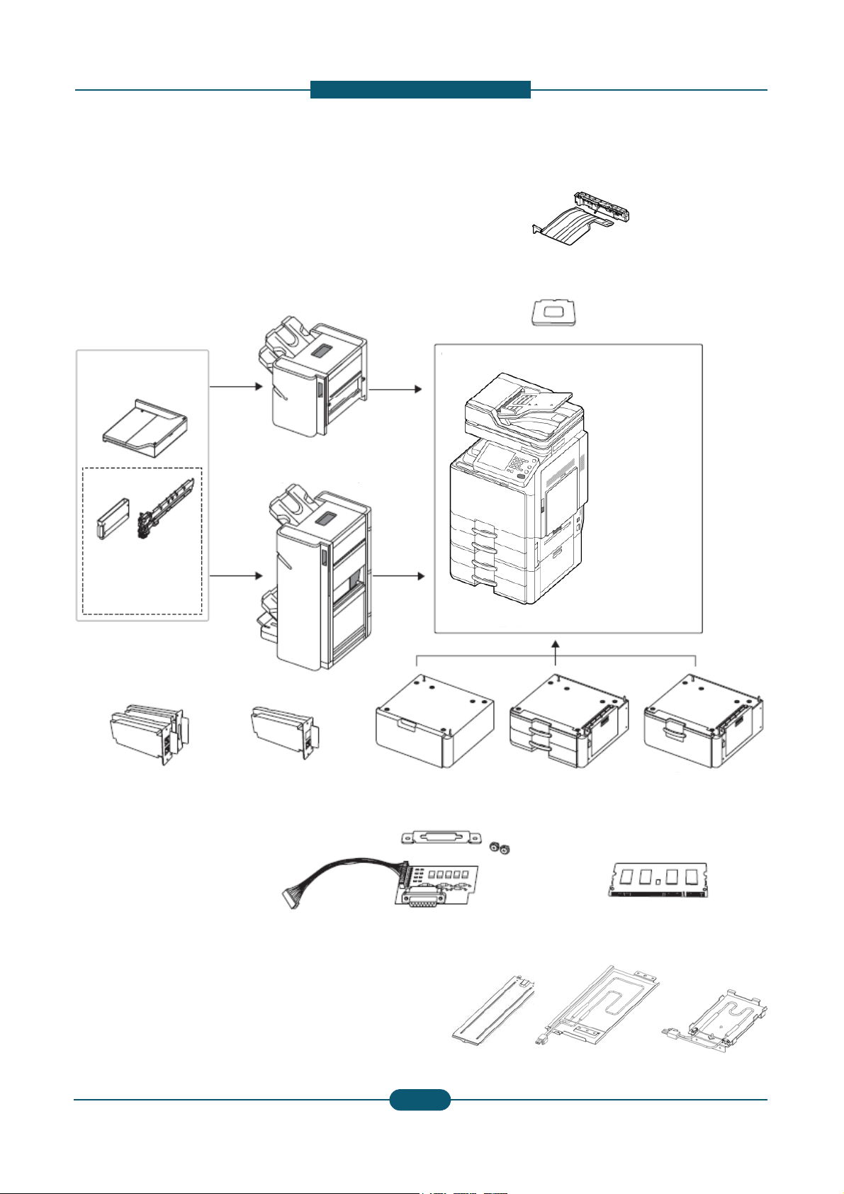
Front view 1
escription
1 DADF Cover
2 DADF width guides
3 DADF input tray
4 DADF output tray
5 Standard tray right bottom door
6 DCF right bottom door
7 DCF (tray3, tray4)*
8 Standard tray (tray1, tray2)
9 Front door
10 Front door handle
11 Control panel
12 Center tray
* Optional device
2
Service Manual
SCX-8030/8040 series
7
SAMSUNG ELECTRONICS
Version 0.05
Page 24
D
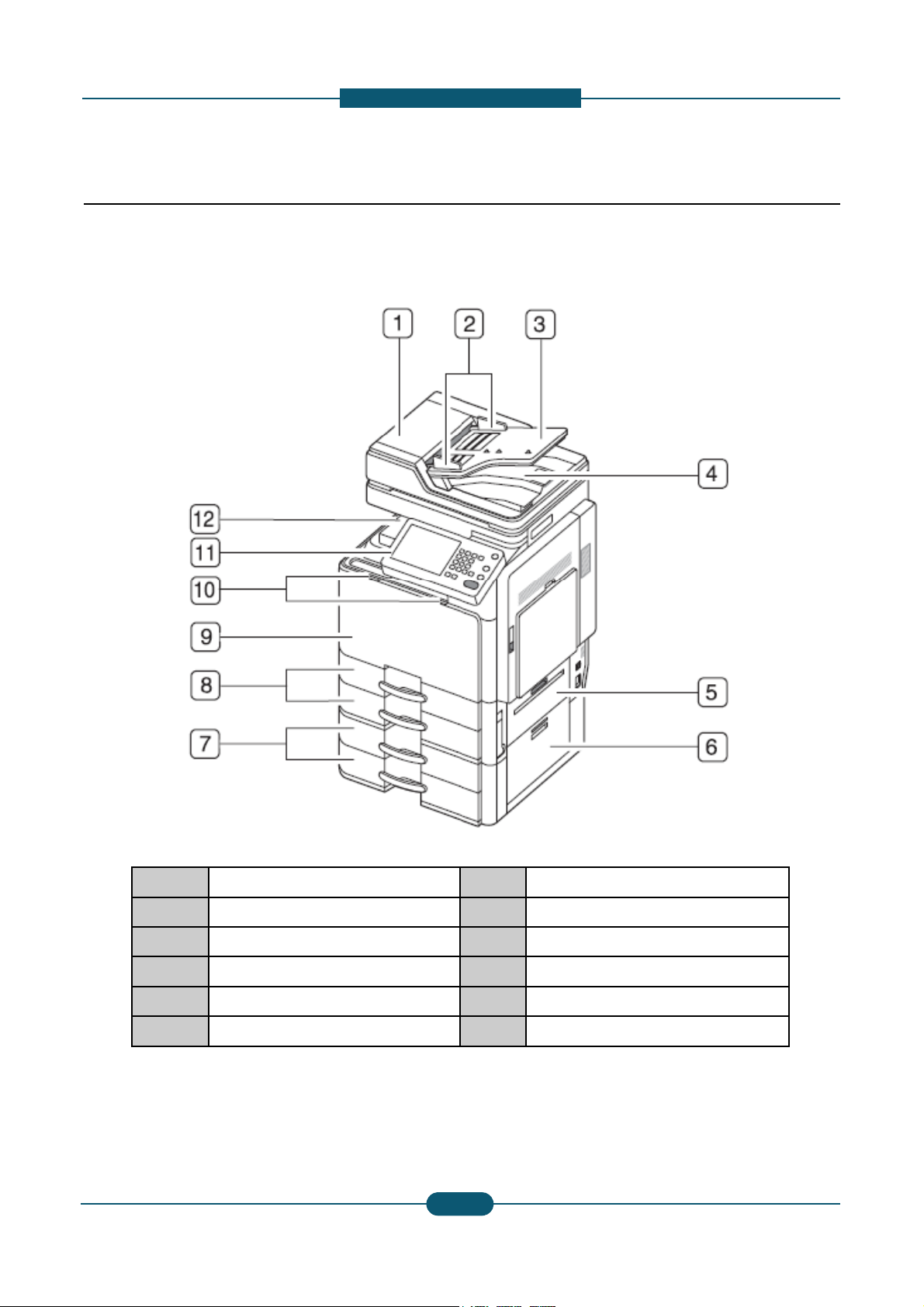
Front view 2
1
S
-
5
P
h
2. Product
escription
canner glass
2 White sheet
3 Multi-purpose tray
4 Multi-purpose tray width guide
* Optional device
ower-switc
6 Power receptacle
7 USB port (2 EA)
8 Job separator*
2
Service Manual
SCX-8030/8040 series
8
SAMSUNG ELECTRONICS
Version 0.05
Page 25
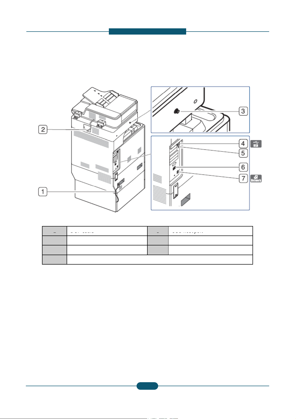
D
Rear view
1
DCF cable
u
-
5
USB host
port
2. Product
escription
2 DADF cable
3 Scanner locking screw
4 USB port (Connection port to comp
6 Finisher connector
7 Network port
ter)
Service Manual
SCX-8030/8040 series
2
9
SAMSUNG ELECTRONICS
Version 0.05
Page 26
D
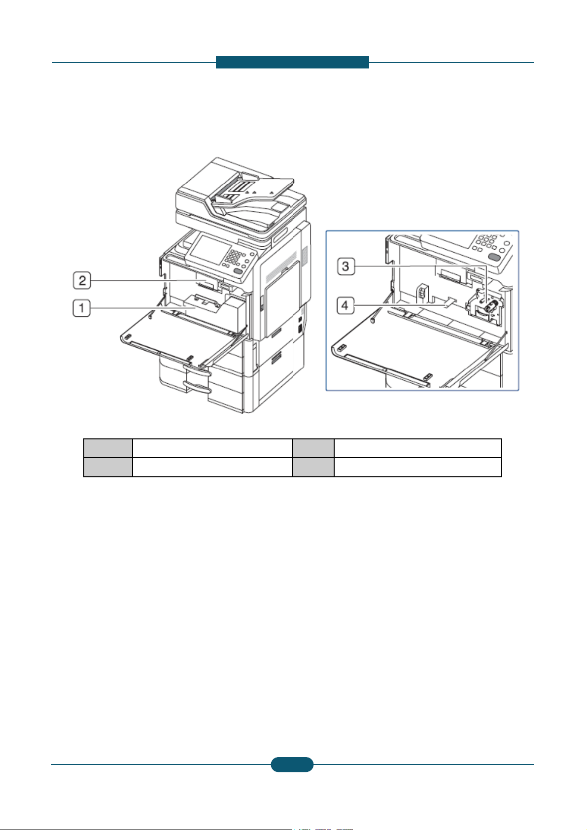
Inner view
o
n
1
2. Product
escription
1 Waste toner container
2 Toner cartridge
NOTE
If you want to see the imaging unit, you need t
lever upward. Then remove the waste toner co
3 Imaging unit
4 Locking lever
remove the waste toner container. Lift the locking
tainer.
2-
Service Manual
SCX-8030/8040 series
0
SAMSUNG ELECTRONICS
Version 0.05
Page 27
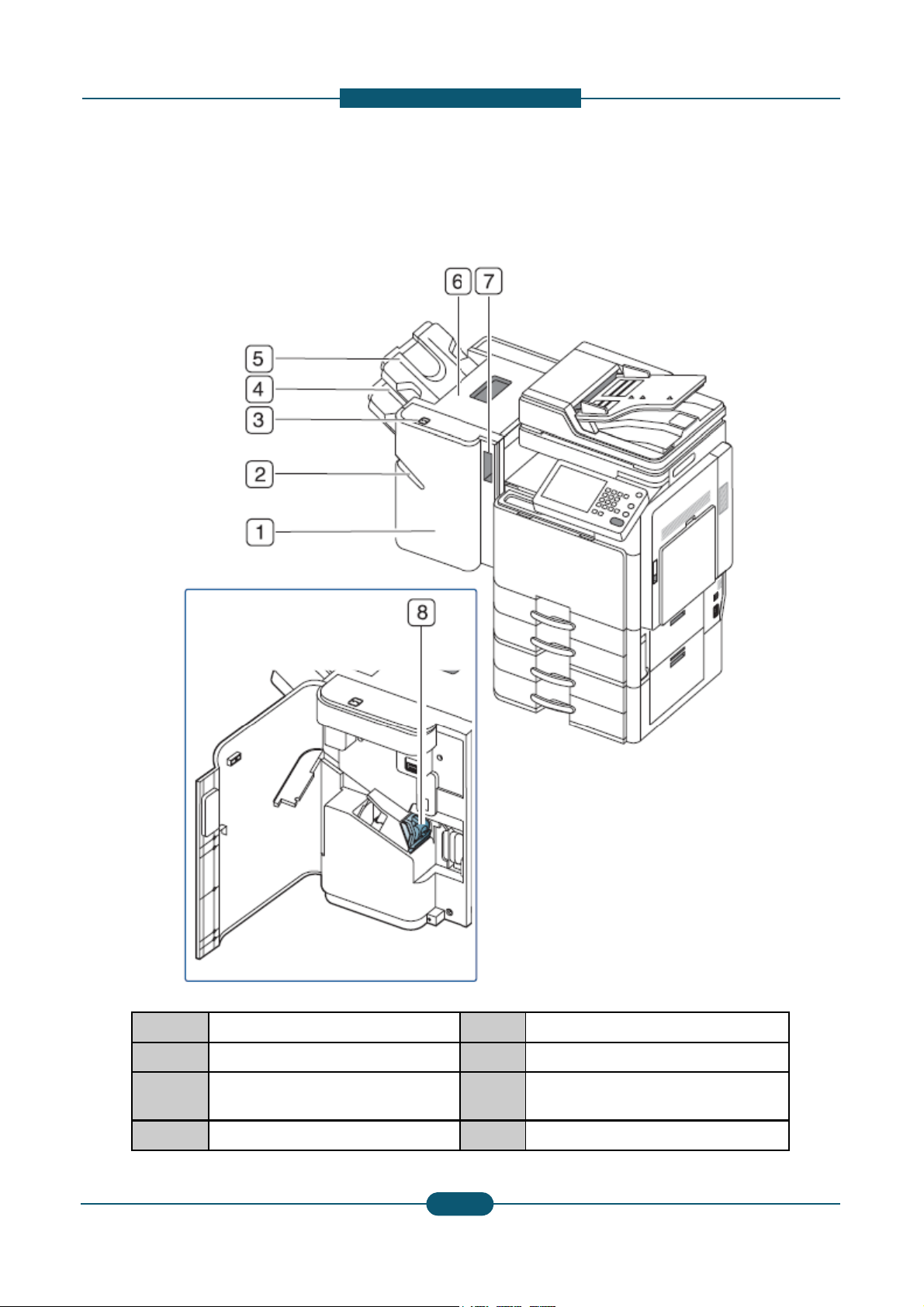
2. Product
D
V
1
escription
iew with standard finisher (option
al)
1 Standard finisher front door
2 Manual stapler
3 Manual stapler button
4 Finishing tray
Service Manual
SCX-8030/8040 series
5 Top tray
6 Top door
7 Standard finisher Front door
handle
8 Staple
2-
1
SAMSUNG ELECTRONICS
Version 0.05
Page 28
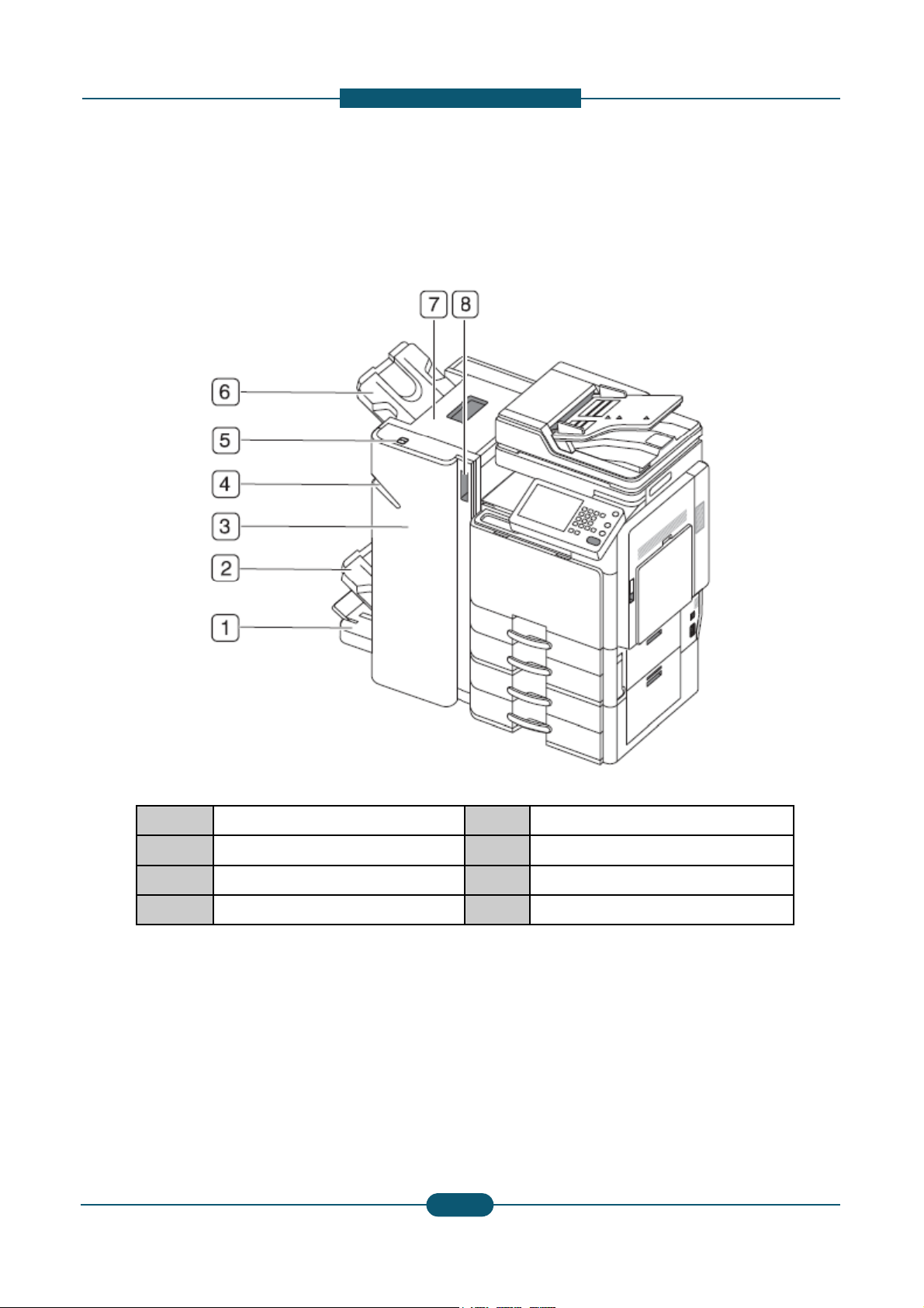
2. Product
D
a
1
escription
View with booklet finisher1 (option
l)
1 Booklet tray
2 Finishing tray
3 Booklet finisher front door
4 Manual stapler
Service Manual
SCX-8030/8040 series
5 Manual stapler button
6 Top tray
7 Top door
8 Booklet finisher front door handle
2-
2
SAMSUNG ELECTRONICS
Version 0.05
Page 29
2. Product
D
a
o
1
escription
View with booklet finisher2 (option
l)
1 Knife wheel
2 Booklet maker handle
3 Fold wheel
4 Booklet jam removal wheel
Note
If you want to open the booklet maker, hold the b
Service Manual
SCX-8030/8040 series
5 Staple
6 Booklet Staple (2 EA)
7 Booklet maker cover
oklet maker handle and pull it out.
2-
3
SAMSUNG ELECTRONICS
Version 0.05
Page 30
2. Product
D
1
r
1
16
escription
Layout
2
3
4
5
6
15
14
13
12
11
7
8
9
1 DADF 7 1sttray
2 Job separator output tray 8 2ndtray
3 Face down output tray 9 Optional
(Stand /
4 Toner cartridges 10 Pick up
10
13 Fuser unit
14 Flatbed scanner
tray
HCF / DCF)
ollers 16 Document input tray
15 Document output tray
5 Laser scanning unit 11 MP tray
6 Imaging units 12 Transfer
Service Manual
SCX-8030/8040 series
roller unit
2-
4
SAMSUNG ELECTRONICS
Version 0.05
Page 31

D
o
Paper Path
D
1
2. Product
escription
The following diagram displays the path the paper foll
Finisher
path
ws during the printing process.
ADF
path
Simplex
path
Duplex
path
Service Manual
SCX-8030/8040 series
2-
5
SAMSUNG ELECTRONICS
Version 0.05
Page 32

D
2.3 Sensor location
a
r
b
S1
SENSOR
HUMIDITY
JC32
00
2
0
0
0
0
0
0
0
0
1
0
r
A3
3211 / A3
3212
A
A
JC92
02302A
A
A
A
2. Product
escription
The following diagrams display the printer sensor loc
tions.
Ref. Description
S2 PBA-WASTE SENSOR RX JC92-0
S3 SWITCH FRONT COVER JC32-0
S4 PHOTO-INTERRUPTER 0604-0
S5 PHOTO-INTERRUPTER 0604-0
S6 PHOTO-INTERRUPTER 0604-0
S7 PHOTO-INTERRUPTER 0604-0
S8 PHOTO-INTERRUPTER 0604-0
S9 SENSOR-PAPER SIZE JC32-0
S10 SENSOR-PAPER SIZE JC32-0
S11 SENSOR-HUMIDITY JC32-0
Service Manual
SCX-8030/8040 series
Pa
Num
t
e
Controller PCB Relative Error Code
159
012
1393 M1-4111
1393 M1-4111
1393 M1-4211
1393 M1-4211
1393 C7-1311
PBA-ENGINE
SCX-8030ND
:
-
SCX-8040ND
: JC92-02221A
013
013
005
2-12-
6
6
A3-3311 / A3-3312
SAMSUNG ELECTRONICS
C7-1130
C7-1110
S2-4210
M1-4111
M1-4211
-
Version 0.05
Page 33

2. Product
D
3
9
7
7
5
8
Ref.Description
r
0
9
1
Controller PCB
Relative Error Code
: JC92
02221A
escription
Ref. Description
S12
PBA-COVER OPEN
SENSOR
Part
Number
JC92-0214
S13 PHOTO-INTERRUPTER 0604-0013
S14 PHOTO-INTERRUPTER 0604-0013
S15 PHOTO-INTERRUPTER 0604-0013
S16 CCD 0605-0011
S17 PHOTO-INTERRUPTER 0604-0013
Controller PCB Relative Error Code
Cover Open Sensor 1,
PBA-SCAN JOINT
2
(JC92-02144A)
3 Home Position Sensor
0
0 SCAN PAPER SIZE
8
PBA-SCAN
(JC92-02170A)
PBA-CCDM
(JC92-02171A)
SCAN PAPER SIZE
S3-3121
1 PBA-ENGINE U1-2115
S20
S21
Service Manual
SCX-8030/8040 series
Charger Clean SNR
Toner SNR
Part
Numbe
JC32-0001
3405-0010
2-12-
S21
S20
PBA-ENGINE
C3-5212
SCX-8030ND
: JC92-02302A
4 C3-5422
SCX-8040ND
-
7
7
SAMSUNG ELECTRONICS
Version 0.05
Page 34

2. Product
D
9
9
9
S34
PHOTO
INTERRUPTER
0604
00139
8
9
1
S43
PBA-ENGINE
M3-1413
M2-1334
escription
S34
S32
S49
S35
S38
S47
S53
S33
S44
S46
S51
S31
S37
S39
S48
S52
S36
S40
S41
S42
S45
S50
Ref. Description
Part
Number
S31 PHOTO-INTERRUPTER 0604-0013
S32 PHOTO-INTERRUPTER 0604-0013
S33 PHOTO-INTERRUPTER 0604-0013
-
-
S35 PHOTO-INTERRUPTER 0604-0013
S36 PHOTO-INTERRUPTER 0604-0013
Service Manual
SCX-8030/8040 series
Controller PCB Relative Error Code
3
M3-2230
M3-1211
3
M3-1213
M3-1214
3 M3-2430
M3-1411
(JC92-02221A)
M3-1414
M2-2411
1
M2-2413
M2-2414
M2-1331
3
2-12-
8
8
M2-1333
SAMSUNG ELECTRONICS
Version 0.05
Page 35

2. Product
D
0
0
0
0
0
0
0
0
0
0
0
0
0
0
0
0
0
1
r
M2-1324
M2-2213
PBA-ENGINE
M1-1113
Ref. Description
Pa
Num
S37 PHOTO-INTERRUPTER 0604-0
escription
rt
be
1393
Controller
PCB
Relative Error Code
M2-2111
M2-2113
M2-2114
S38 PHOTO-INTERRUPTER 0604-0
S39 PHOTO-INTERRUPTER 0604-0
S40 PHOTO-INTERRUPTER 0604-0
S41 PHOTO-INTERRUPTER 0604-0
S42 PHOTO-INTERRUPTER 0604-0
S43 PHOTO-INTERRUPTER 0604-0
S44 PHOTO-INTERRUPTER 0604-0
S45 VR-SLIDE 2102-0
S46 PHOTO-INTERRUPTER 0604-0
S47 PHOTO-INTERRUPTER 0604-0
S48 PHOTO-INTERRUPTER 0604-0
1393
M2-1325
M2-1321
1393 Curl Sensor 1
1393 Curl Sensor 2
1393 MP Long Size
1393
M2-2215
M2-2216
M2-1213
1381
M2-1214
M2-1211
1399 OHP Sensor
1020 MP Size Sensor
(JC92-02221A)
1393 M1-1610
M1-1113
1381
M2-1124
M2-1125
M2-1121
1393
M1-5112
S49 PHOTO-INTERRUPTER 0604-0
S50 PHOTO-INTERRUPTER 0604-0
S51 PHOTO-INTERRUPTER 0604-0
S52 PHOTO-INTERRUPTER 0604-0
S53 PHOTO-INTERRUPTER 0604-0
Service Manual
SCX-8030/8040 series
1393 M1-4111
1393 S2-4A10
M1-1213
1381
M2-1134
M2-1135
M2-1131
1393
M1-1213
M1-5212
1393 M1-4211
2-12-
9
9
SAMSUNG ELECTRONICS
Version 0.05
Page 36

2. Product
D
r
a
sensor, Tray Paper Stock sensor, MP Feed sensor, Tr
s
2
Feed sensor, Registration sensor, and Drive
DUPLEX
2.4 Paper handling section
escription
This section describes how the system picks up pape
transports it to the transfer position. The paper feedin
Forward roller, Retard roller, Transport roller, Registr
system for these components. The Transport motor i
2.4.1 Overview
The following diagrams display the positions of the pa
2NDEXIT
(OPTION)
from the Paper tray or Multi-Purpose (MP) tray and
g system mainly consists of the Pickup roller,
tion roller, MP Paper sensor, Paper Empty
used to drive all of these rollers.
per path rollers.
EXIT
SIDE
MPF
CASSETTE
Service Manual
SCX-8030/8040 series
PICKUP
2-22-
0
0
TAKEAWAY
TR
REGI
SAMSUNG ELECTRONICS
Version 0.05
Page 37

D
2NDExit tray paper
t
q
qy
MPF solenoid
e
t
2
yp
t
full detection
2NDEXIT (OPTION)
2NDExit tray jam detection
st
Exit tray paper
1
full detection
1stExit tray jam detection
Return path solenoid
Exit
2. Product
Re
escription
Return transport path
detection
urn
Duplex jam detection1
Paper jam detection
Paper regi. time detection
Transparency detection
Tray1 paper remaining
uantity detection
Tray1 paper
empty detection
Paper tray
Tray1 paper
size detection
Fuser
Paper curl detection
OPC
Regi
Tray1 upper limit detection
Tray1 lift
motor
Pick Up
Duplex
Duplex jam detection2
Duplex clutch
MPF
MPF
clutch
MPF media
MPF paper
empty
size detection
(Long media)
detection
MPF media size detection
Tray1 transport detection
Tray2 paper
empty detection
Tray2 paper
size detection
Service Manual
SCX-8030/8040 series
Tray2 lift
motor
Tray2 pap
quantity de
2-22-
r remaining
ection
1
1
Tray2 transport detection
Tray2 upper limit detection
SAMSUNG ELECTRONICS
Version 0.05
Page 38

2. Product
D
t
s
r
T
Detects t
e
i
p
e
s
Tray2 paper remaining quantity
r
e
i
p
e
T
y
o
a
1stExit tray paper full detection
Detect paper full
j
Duplex jam detection 2
Detects duplex jam 2
o
p
s
pp
s
e
2
y
ty
CN12@ C
PBA, 3Pi
y
y
CN7@ BOTTLE Joint
PBA, 3Pin
j
CN4 @ SIDE JOINT PBA, 3Pin
@,
y
escription
Name Func
Tray1 paper size detection Detects tray1 paper
Tray1 paper remaining quantity
detection
ray1 paper empty detection
Tray1 upper limit detection Detects tray1 upper l
Tray1 transport detection Detects tray1 paper
Tray1 Lift Motor Lifting knock up plat
Tray2 paper size detection Detects tray1 paper
detection
Tray2 paper empty detection Detects tray2 paper
Tray2 upper limit detection Detects tray2 upper l
Tray2 transport detection Detects tray2 paper
Tray2 Lift Motor Lifting knock up plat
Paper regi. time detection Detects paper regi.
Transparency detection Detects transparenc
Detects tray1 paper
Detects tray2 paper
ray1 paper
ion Connector & pin information
ize (installation) CN16@ Cassette Joint PBA, 4Pin
emaining quantit
mp
mit CN12@ Cassette Joint PBA, 3Pin
ass CN12@ Cassette Joint PBA, 3Pin
ize (installation) CN16@ Cassette Joint PBA, 4Pin
emaining quantit
mpt
mit CN13@ Cassette Joint PBA, 3Pin
ass CN13@ Cassette Joint PBA, 3Pin
ime CN10@ Engine PBA, 3Pin
CN11@ Cassette Joint PBA, 6Pin
assette Joint
CN15@ Cassette Joint PBA, 3Pin
CN11@ Cassette Joint PBA, 6Pin
CN13@ Cassette Joint PBA, 3Pin
CN15@ Cassette Joint PBA, 3Pin
CN10@ Engine PBA, 3Pin
n
Paper curl detection Detects paper positi
Paper jam detection Detects fuser jam
st
1
Exit tray jam detection
2ndExit tray jam detection
2ndExit tray paper full detection
Return transport path detection Detects return(2
Detects 1stexit tray j
Detects 2ndexit tray
Detects paper full
nd
ex
Return path solenoid Change paper path
Duplex jam detection 1 Detects duplex jam 1
Duplex clutch Duplex driving contr
MPF solenoid MPF pick up roller u
MPF clutch MPF driving control
MPF media size detection Detects MPF paper
MP media size detection
(Long media)
Detects MPF paper
MPF Paper empty detection Detects MPF paper
n CN3@ SIDE JOINT PBA, 6Pin
CN5 @ SIDE JOINT PBA, 3Pin
m CN7@ BOTTLE Joint PBA, 3Pin
am CN29 @ Engine PBA, 3Pin
CN29 @ Engine, 3Pin
it tray) paper pass CN7@ BOTTLE Joint PBA, 3Pin
CN7@ Engine PBA, 2Pin
CN5 @ SIDE JOINT PBA, 3Pin
l CN6 @ SIDE JOINT PBA, 2Pin
/down CN2 @ SIDE JOINT PBA, 2Pin
CN2 @ SIDE JOINT PBA, 2Pin
ize CN7 @ SIDE JOINT PBA, 3Pin
ize CN7 @ SIDE JOINT PBA, 3Pin
mpt
CN2 @ SIDE JOINT PBA, 3Pin
Service Manual
SCX-8030/8040 series
2-22-
2
2
SAMSUNG ELECTRONICS
Version 0.05
Page 39

D
2.4.2 Components
i
2
2
forward rollers
19
13
Tray 4 feed roller
full
2. Product
escription
The following diagrams display the positions of the pr
27
26
23
22
21
nter components
25
24
20
17
16
14
18
15
Tray 1 Paper tray
1
Tray 2 Paper tray
2
Tray 3 Paper tray
3
Tray 4 Paper tray
4
Tray 1 pick up / retard /
5
Tray 2 pick up / retard /
6
forward rollers
Tray 3 pick up / retard /
7
forward rollers
Tray 4 pick up / retard /
8
forward rollers
MP Tray pick up / retard
9
/ forward rollers
Tray 1 feed roller
10
Tray 2 feed roller
11
Tray 3 feed roller
12
Bypass feed roller
14
9
Sensor registration
13
15
Roller registration
16
Roller transfer
17
Sensor paper curl
18
Roller fuser
19
Sensor fuser out
20
Roller exit
21
Roller face down exit
22
Actuator face down bin
23
Sensor duplex return
24
Roller duplex return
25
Roller 2nd exit
26
Actuator 2nd Exit bin full
27
10
5
1
11
6
12
7
3
8
4
Service Manual
SCX-8030/8040 series
2-22-
3
3
SAMSUNG ELECTRONICS
Version 0.05
Page 40

D
2.4.3 Functions
d
Pickup Roller (paper tray and MP tray)
p
Retard
)
r
h
y)
p(ppy y)
e
a
e
This sensor detects whether paper is set in the bypass
o
a
d
c
Feed Sensor
e
r
r
2
tray
When it is, MP tray always comes
2. Product
escription
This section describes the functions of the paper han
This roller moves up and down and draws out the pap
the feed roller.
Forward Roller (paper tray and MP tray)
This roller is placed against the Retard roller. It trans
transport roller.
roller (paper tray and MP tray
This roller is placed against the feed roller. When two
pickup roller, the load of the torque limiter of the Reta
sheets. As a result, the Retard roller is stopped and t
only one sheet is transported from the pickup roller, th
roller.
Transport Roller (paper tray and MP tra
This roller transports the paper sent from the feed roll
Registration Roller
Paper transported from the transport roller is pushed
edge of the paper. Then, the registration rollers rotat
ling components.
er from the bypass tray or drawer and transports it to
orts the paper from the pickup roller to the
sheets of paper or more are transported from the
d roller is heavier than the frictional force between the
e lower paper does not advance any further. When
e Retard roller rotates following the feed
r to the registration roller.
gainst the registration roller which aligns the leading
to transport the paper to the transfer unit.
MP tray Paper Sensor
before drawer feeding.
Empty Sensor (Tray 1 / Tray 2)
This is a transmissive-type sensor and it detects the a
When there is no paper in the drawer, the actuator bl
determines that there is no paper.
Paper Stock Sensor
This is a transmissive-type sensor which detects the
actuator. When the remaining paper is consumed an
blocks
the light path for the transmissive-type sensor to dete
This sensor detects if the leading edge or trailing edg
detects jamming such as missfeeding.
Registration Sensor
This sensor detects that the leading edge of the pape
trailing edge of the paper has passed the registration
.
vailability of paper in the drawer by using an actuator.
cks the light path of the sensor, and the sensor
mount of remaining paper in the drawer using an
approximately 100 sheets remain, the actuator
t that there is less paper.
of the paper has passed the feed roller. It also
has reached the registration roller and that the
oller.
Service Manual
SCX-8030/8040 series
2-22-
4
4
SAMSUNG ELECTRONICS
Version 0.05
Page 41

D
2.4.4 Paper tray
e
p, pp
A
m
•
Paper
:
7
e
o
2
2. Product
escription
The paper trays consist of the Main trays, Optional tra
The MP tray is located on the right side of the machin
envelopes, and custom size paper.
Paper size is set using the Size Guides in each tray.
paper size.
ys (DCF,HCF), and one Multi-Purpose (MP) tray.
and allows feeding of specialty media stock,
djust the Front, Rear, and End Guides to match the
Specification
• Structure : Paper tray Type, Auto Paper Size
• Capacity : 520 Sheets ( 80g/㎡ standard Xerox Pre
-. Plain paper : A5, A4, A3, B5, B4, Letter, 11"×1
-. Special Paper : 12"×18", Label (Label : 50 she
• Weight : plain paper 60 ~ 163 g/㎡
• Plate knock up Lift type : Lift Motor + Up Limit Sens
Service Manual
SCX-8030/8040 series
inum)
"(Ledger), Statement, Legal
ts)
r
2-
5
SAMSUNG ELECTRONICS
Version 0.05
Page 42

D
2.4.5 Pick up unit
w
o
roller serve to make sure that a single sheet of paper i
c
2
s moved to the paper path, and the paper is moved
2. Product
escription
When pickup takes place, the pickup roller moves do
The pickup roller moves down when the pickup solen
as far as the registration roller by the work of the verti
pickup roller:
Actuator-Empty Sensor
n to come into contact with the surface of the paper.
id is activated. The forward roller and the separation
al path roller. The following is a diagram of the
Forward Roller
Retard Roller
Pick Up Roller
Service Manual
SCX-8030/8040 series
2-
6
SAMSUNG ELECTRONICS
Version 0.05
Page 43

D
t
l
2.4.6 Registration unit
roller in order to match paper and an image on the dru
R
G
Specification
m
m
m
Margin
C
2
the predetermined registration point
2. Product
escription
The registration roller is driven by the registratio n mul
between the registration roller and the registration mu
ROLLER-
JAM REMOVAL
LEVER
RE
i motor. The registration clutch (CL6) is located
ti motor, and it controls ON/OFF of the registration
at
.
SHAFT-REGI
EGI
I SENSOR
•Skewin Simplex
-. Top Skew : 2.0mm/241.3mm ( Option : 2.5m
-. Side Skew : 1.5mm/180.5mm ( Option : 2.0m
• Skew in Duplex
-. Top Skew : 3.0mm/241.3mm ( Option : 3.5m
-. Side Skew : 2.3mm/180.5mm ( Option : 2.5
• Dog Ear, Trees, Nicks, Wrinkling
-. Plain Paper : 1/5,000
-. Special Media : 1/1,000
•
-. Top Margin : 4.23 ± 2 mm ( Tray3, 4, HCF :
-. Left / Right Margin : 3 ± 2 mm ( Tray3, 4, H
-. Duplex Top Margin : 4.23 ± 2.5 mm ( Tray3
-. Duplex Side Margin : 3 ± 2.5 mm ( Tray3, 4
/241.3mm )
m/180.5mm )
/241.3mm )
m/180.5mm )
4.23 ± 2.5 mm )
F : 3 ± 2.5 mm )
, 4, HCF : 4.23 ± 3.0 mm )
, HCF : 3 ± 3.0 mm )
Service Manual
SCX-8030/8040 series
2-22-
7
7
SAMSUNG ELECTRONICS
Version 0.05
Page 44

D
2.4.7 MPF unit
P
C
Wh
[A]
n
2
MPF Clutch
The following is a diagram of the MFP unit:
MPF Pick up roller
2. Product
escription
Empty sensor
MPF
Tray
Specification
• Tray capacity : 100 sheets( 80g/㎡ standard Xerox
• Media Size : Max 12”×18” (305×457㎜) / Min 3.87
• Media weight : Plain paper 60 ~ 216 g/㎡
• Feeding speed : 40 ppm (SCX-8040ND), 30 ppm (S
•Auto size sensing : A6 SEF, Statement SEF, B5 S
LTR(Letter) LEF, A3, A4 LEF
Long paper sensor
reminum )
”×5.82” (98×148㎜)
X-8030ND) in Letter/A4 LEF (Long Edge Feeding)
EF, A4 SEF, A5 LEF, B4 B5(JIS) LEF, 11x17,
Paper Separation
en the by-pass paper detection
sensor detects
the by-pass solenoid [B] drops the pick-up roller [C] o
After that, the pick-up roller moves one
sheet of paper to the feed roller.
This machine uses an FRR (Feed and
Reverse Roller) system for feeding paper.
There is friction between the feed roller [E]
and Retard roller [D]. This friction separates
the top sheet of paper from the stack.
Service Manual
SCX-8030/8040 series
paper and the machine gets a by-pass printing job,
to the top of the paper stack on the by-pass tray.
2-
8
SAMSUNG ELECTRONICS
Version 0.05
Page 45

D
2.5 Image creation
v
e
s
Drum unit and Development unit. The Drum unit has a
m
b
a
n
m
e
r
u
v
g
2
g
gy
OPC drum, a scorotron (which charges the OPC)
v
g
g
2. Product
escription
This section describes the image creation process us
2.5.1 Printing process ov er
This mono printing system includes the LSU with a la
d by the printer.
iew
er beams, a imaging unit and transfer unit.
This machine uses single Imaging unit and dual laser
a light-guide ( which transfers the LED’s light in the
The OPC drum[A] is charged with a nega tive voltage
LSU (Laser Scanning unit)[B]. The light produced by
surface of the OPC drum. The negatively charged to
electric filed. The toners(real image) on the OPC dru
applied to the transfer roller[c].
1. Charging the OPC drum: The scorotron gives th
2. Laser exposure: Light produced by a laser diode i
mirrors .
3. Development: This machine uses a dual-compon e
negatively charged toner to the latent image on the dr
4. Transfer: The transfer rollers opposite the OPC dr
media (e.g. paper, OHP film, etc).
5. Cleaning for OPC drum: The cleaning blade remo
transfer to the paper.
6. Quenchin
lamps at the end of every job.
for OPC drum: Quenching is done by
beams for mono printing. The Imaging unit consists of
achine) and cleaning blade.
y the scorotron and is exposed by the light from the
laser creates a latent image by discha rgin g on the
ers are attracted to the latent image due to and
are moved to the transfer media by the positive bias
drum negative charges.
radiates the charged OPC through the lens and
nt development system . The magnetic roller carries
m surface.
ums transfer toner from the drums to the transfer
es remaining toners on the drum surface after image
illuminatin
the whole area of the drum with the LED
,
Service Manual
SCX-8030/8040 series
2-22-
9
9
SAMSUNG ELECTRONICS
Version 0.05
Page 46

D
2.5.2 Imaging unit
e
e
d
n
e diameter of the dru
ab
e d a ete o t e d u s 30 (c cu e e ce ab
o
r
u
Scorotron
3
2. Product
escription
2.5.2.1 Imaging unit ov ervi
The imaging unit consists of OPC drum unit and the d
drum, a scorotron which charges the OPC, a light-gui
and cleaning blade. The development unit has a mag
and a TC (Toner Concentration) sensor.
Th
The developing gap between a drum and the corresp
they assembled as one Imaging unit in the factory.
The cleaning blade removes remaining toner on the d
The CRUM chip in the image unit stores the data abo
m is 30 mm (circumference:
Light guide
w
velopment unit. The OPC drum unit has an OPC
e ( which transfers the LEDs light in the machine)
etic roller, two mixing augers, developer, a Dr-blade
94.2 mm).
nding magnetic roller cannot be adjusted becaus e
um surface after image transfer to the transfer belt.
t the Imaging unit.
Cleaning blade
Mixing Auger
OPC Drum
Magnetic Roller
Service Manual
SCX-8030/8040 series
2-32-
0
0
SAMSUNG ELECTRONICS
Version 0.05
Page 47

D
2.5.2.2 Drum drive
D
3
C
OPC
2. Product
escription
OPC and Mag Roller is driven by a motor. The OPC
coupling.
Drive motor BLDC
Coupling
Drum-K
rum and Mag roller are supplied with power from the
Drive transmission gear
BLDC motor
Service Manual
SCX-8030/8040 series
Gear-Drive OPC
oupling
Coupling Deve
2-32-
1
1
SAMSUNG ELECTRONICS
Version 0.05
Page 48

D
2.5.2.3 Development
y
the magnetic roller [A] by the two mixing augers [B] an
A
o
3
attracted onto the surface of the OPC drum. The
2. Product
escription
This machine uses a dual-component development s
drum unit and development unit). A new unit contains
diameter of the magnetic roller is 18mm.
n imaging unit has a TC (Toner concentration) sens
for controlling the operating range of toner density. Th
some information about the imaging unit is stored.
[A] Magnetic Roller
stem and has an imaging unit (which includes the
345g of toner. The developer in the unit is supplied to
is
r[C]. The TC sensor [C] in the imaging unit is used
e imaging unit is equipped with a CRUM in which
[C] TC
Sensor
[B]
Mixing
Auger
[B] Mixing Auger
Service Manual
SCX-8030/8040 series
2-32-
2
2
SAMSUNG ELECTRONICS
Version 0.05
Page 49

2. Product
D
a
a
h
e
3
escription
Two mixing augers [A] circulate the developers (which
backward to agitate the developer in order to mix the c
This occurs at the following times:
• During TC calibration
• During development.
Filters [B] on the top of the development unit ensure th
During the operating , this prevents contamination of t
[B] Filt
are mixtures of carriers and toners) forward and
rriers and toners well.
t the internal pressure does not become too high.
e imaging unit by the toner.
r
[A] Auger
2-32-
3
Service Manual
SCX-8030/8040 series
3
SAMSUNG ELECTRONICS
Version 0.05
Page 50

D
2.6 Fuser unit
d
A
a
2.6.1 Fuser unit overview
P
ili
f
a
e
e
th
r
t
u
3
Halogen L
htl
2. Product
escription
This section describes the image fusing process use
n instant fusing system is used. This has a faster wa
roller system.
The drum-fuser belt is made of 3 thin layers, so is he
ressure roller is made of soft s
cone rubber, which
The drum-fuser belt contains two fusing lamps (one la
other lamp, side heating lamp, heats the ends in the
NC sensors (non-contact type thermistors), located n
control the temperature of the drum-fuser belt at the c
ermistors and two thermostats, located at the cente
overheating by the heating lamps.
Temperature is normally controlled by turning on and
respectively, corresponding to predetermined target
by the printer.
rm-up time than a conventional fusing and pressure
ted quickly by halogen lamp inside.
attens slig
y, increasing the fusing nip.
mp, center heating lamp, heats the center and the
xial direction).
ar the center and the rear end of the drum-fuser belt,
nter and the ends, respectively. Two NTC
and the side, protect the fusing system from
off the center heating lamp and side heating lamp,
emperatures.
Pressure Roller
Dr
m-Fuser Belt
Thermistor
Center : 0.5mm-1.0mm distance
Side : Contact
Thermostat
NC Sensor
Service Manual
SCX-8030/8040 series
2-
4
SAMSUNG ELECTRONICS
Version 0.05
Page 51

2. Product
D
s
L
c
s
T
r
a
T
e
p
pp
p
e
i
e
h
e
f
3
2.6.2 Fuser unit component
The Fuser unit includes the following components:
escription
1. Center heater lamp (LAMP1) / Side heater lamp (
These halogen lamps heat the drum-fuser belt. The
lamp (LAMP2) are lit alternately to heat the drum-fu
Each heater lamp has its coil in a different location.
the center, those of the side heater lamp (LAMP2) a
the drum-fuser belt so that they will not rotate separ
2. Drum-fuser belt
It receives heat from halogen lamp inside and condu
reduces warming up time and mode changing time.
the surface of the fuser belt is fluorinated. Rigid ass
surface of the fuser belt at nip and is pressed on the
between fuser belt and pressure roller.
ni
3. Pressure roller
The pressure roller is a rubber roller which ensures
fuser belt. It is driven by external driving mechanism
4. NC sensors
NC sensors detect the surface temperature of the ce
the heater lamps.
AMP2)
enter heater lamp (LAMP1) and the side heater
er belt.
he coil of the center heater lamp (LAMP1) is in
e on both sides. The heater lamps are fixed inside of
tely.
cts heat to toner and paper. The thin fuser belt
o prevent the fuser belt from adhering to the toner,
mbly located inside the fuser belt contacts inner
pressure roller by springs in order to ensured proper
roper nip width between the pressure roller and
and drives fuser belt by pressure.
nter and the rear end of the fuser belt which controls
5. Thermistor (Center : 0.5mm-1.0mm distance, Sid
Thermistors, located at the center and rear end(non
overheating.
6. Thermostat
These thermostats cut off the power supply to the h
becomes abnormally hot as a result of problems suc
These thermostats are used to prevent abnormal op
replaced (as well as the other damaged parts in the
Service Manual
SCX-8030/8040 series
: Contact)
mage position), protect the fusing system from
ater lamps by opening the circuit when the fuser belt
as a NC sensor malfunction.
ration. When the thermostat is triggered, it must be
user unit).
2-
5
SAMSUNG ELECTRONICS
Version 0.05
Page 52

D
2.6.3 Fuser unit drive
e
dri
ith th
[B]
3
2. Product
escription
The fusing/paper exit motor [A] drives the pressure roll
ven by pressure w
e pressure roller
.
Fuser Belt [C]
r [B] through the gear train. The fuser belt [C] is
Exit Motor [A]
Pressure Roller [B]
2-
Service Manual
SCX-8030/8040 series
6
SAMSUNG ELECTRONICS
Version 0.05
Page 53

2. Product
D
detect the standby temperature. Then the CPU raises
e
g
o
o
h
h
e
h
3
the temperature to the
printing temperature
2.6.4 Temperature control
escription
When the main switch turns on, the CPU turns on the
Thermistor2
Thermistor1
NC Sensor2
NC Sensor1
Th
fusing lamp. The lamp stays on until the NC sensors
.
Lamp 1(700W) : Center heating
rmostat 1
Thermostat 2
Overheat Protection
The CPU cuts power to the fusing lamp in the followin
• The fuser belt temperature detected by the NC sens
• The fuser belt temperature detected by the thermist
The following components are used if thermistor over
• Two thermostats for the fuser belt get into line with t
• If one of the thermostat temperatures becomes high
lamp. If the other thermostat temperature becomes
fusing lamp.
Lamp 2(600W) :
Side heating
cases:
rs becomes higher than 198℃.
rs becomes higher than 210℃
eat protection fails.
e common ground line of the fusing lamp.
r than 170°C, it opens and cuts power to the fusing
igher than 170°C, it also opens and cuts power to the
Service Manual
SCX-8030/8040 series
2-
7
SAMSUNG ELECTRONICS
Version 0.05
Page 54

2. Product
D
O
n
1
5
1
3
2
P/Mirror Motor
2.7 Laser Scanning Unit
escription
2.7.1 Laser Scanning Unit
The Laser Scanning Unit (LSU) consisted of 1 polygo
surface of 1 OPC drum. For this process, there are co
optical path. Also, LSU has the cover glass device to
with set, LSU has the LD PBA on front side.
verview
motor and 1 LD unit, forms a latent image on the
llimator lens, cylindrical lens and F-Theta Lens on
protect the LSU from the contamination. For interface
Scan direction
Service Manual
SCX-8030/8040 series
Information
Part Code : JC97-03700A [LSU]
1 LD PBA
3 F1 Lens
4 F2 Lens
342
2-
8
5 Cover glass
SAMSUNG ELECTRONICS
Version 0.05
Page 55

2. Product
D
a
[A]
t
h
Laser Diode : Dual
Beam
3
Laser Diode : Dual
Beam
escription
2.7.2 Laser Scanning Optic
[B]
The laser beam is emitted directly from a polygon mo
determine the scanning line and image position. This i
The LSU has 2 types depending on printing speed. T
l path
K
[C] [D]
or [A] to OPC [D]. F1 Lens [B] and F2 Lens [C]
s adjusted at the factory.
e difference between the 2 models is shown below.
Mode SCX-8040 (40 ppm)
LD Unit
P/Motor
speed
Process
Speed
H/W
interface
driving IC : for Dual LD
PCB : 40/30 ppm common use
22,677 rpm
192 mm/sec
Harness : 22 Pin
(Interface with set )
SCX-8030 (30 ppm) Remarks
driving IC : for Dual LD
PCB : 40/30 ppm common use
16,299 rpm
138 mm/sec
Harness : 22 Pin
(Interface with set )
Service Manual
SCX-8030/8040 series
2-
9
SAMSUNG ELECTRONICS
Version 0.05
Page 56

2. Product
D
e
P
A
a
4
escription
2.7.3 Laser synchronizing d
The machine has a beam detector sensor board (BD
The BD board detects the point of scanning start.
Main Scan Start Detection
beam is detected by the BD PBA at the scanning st
(Hsync).
The picture below shows the data scanning direction.
[A]
tectors
BA). It is located on the corner (mark “A”)
rt point and creates the horizontal sync signal
2-
Service Manual
SCX-8030/8040 series
0
SAMSUNG ELECTRONICS
Version 0.05
Page 57

2. Product
D
a
2.8.1 Drive Motors
1
7
6
t
4
E-CLT
1
Exit drivi
2.8 Printer Drive system
escription
This section describes the printer drive system parts
The following diagram displays the locations of the pri
2
nd process.
nter drive motors.
8
5
4
3
The following table list the descriptions for the tagged
No. ITEM Type Q
1 Duplex Return HB-STEP 1
2 Fuser/Exit
BLDC 1
9
drive locations.
Duplex return driving -
Fuser/Exit driving -
Function
Related
error
ng -
Service Manual
SCX-8030/8040 series
2-42-
1
1
SAMSUNG ELECTRONICS
Version 0.05
Page 58

2. Product
D
t
1
2
1
1
BLDC
1
3
1
18WTB
PM-STEP
1
2
4
MP / Regi / Duplex driving
-
Waste Tank
leveling
-
escription
No. ITEM Type Q
HB-STEP
3 Pick-Up
E-CLT
4Duct PM-STEP
5
Toner supply
gear box
DC
MP / Regi /
6
Duplex
E-CLT
OPC / DEVE BLDC
7 PR Release PM-STEP
9CST Lift DC
Function
Pick-Up Roll driving -
1st, 2nd Pick up
Toner Duct driving -
Toner transfer in Toner Bottle
driving Duct
MP / Regi / Duplex control -
OPC/DEVE -
PR Release driving -
1st , 2nd CST Lift -
Related
error
-
-
Service Manual
SCX-8030/8040 series
2-42-
2
2
SAMSUNG ELECTRONICS
Version 0.05
Page 59

2. Product
D
D
(MP/REGI/DUP)
R
4
escription
2.8.2 Main drive unit (OPC,
Front View
BLDC
EVE, MP, REGI, DUPLEX)
BLDC
(OPC/Dev)
egi Control Clutch
Rear View
OPC Coupling
Deve (Auger)
Coupling
Duplex Drive Gear
REGI Drive Gear
MP Drive Gear
Service Manual
SCX-8030/8040 series
Information
Part Code : JC93-00118A [DRIVE MAIN]
2-42-
3
3
SAMSUNG ELECTRONICS
Version 0.05
Page 60

D
2.8.3 Pick-up Driv e
t
r
cH-
Step
Belt
Pulley Gear
Gear
E-C
4
Information
Pick
up 1 driving
The following is a diagram of the Pick-up drive:
2. Product
Mic
Clu
escription
ro-
ch
Feed
Pick-up
Coupling
Feed
Power Train
Pick-up : Same H-Step moto
Rising 2 tray by e-
Gear
Pick-up
Part Code : JC93-00065A [DRIVE-PICK UP]
is
lutch
-
Feed 1 driving
Service Manual
SCX-8030/8040 series
Gear Gear
Feed 2 driving
2-42-
4
4
Gear E-Clutch Pick-up 2 driving
SAMSUNG ELECTRONICS
Version 0.05
Page 61

D
2.8.4 Fuser/Exit Drive
e
Micro
Clutch
c
e
4
Part Code : JC93
-
00119A [DRIVE
-
EXIT]
2. Product
escription
The following is a diagram of the drives that power th
-
Fuser, Exit systems:
HB-Step
Duplex Return Drive
BLDC
Exit Drive
Power Train
-Fuser/Exit : BLDC is interlo
-Duplex Return : HB-Step is
1. BLDC FUSER A/B Fuser Roll driving
EXIT RDCN EXIT IDLE A
2. H-Step DUP RDCN
Duplex R
Fuser Drive
Information
ked.
interlocked.
EXIT IDLE B Clutch-E Exit Roll driving
turn driving
Service Manual
SCX-8030/8040 series
2-42-
5
5
SAMSUNG ELECTRONICS
Version 0.05
Page 62

2. Product
D
u
4
2.8.5 Toner Duct drive
The following is a diagram of the Toner Duct drive:
GEAR DUCT RDCN
Photo Interrupter
escription
PM Step
Power Train PM Step motor : Toner Duct
Step (PM) GEAR DUCT RDCN
Toner D
2.8.6 Drive of Toner Supply
The following photo displays the location of the Toner
Information
Part Code : JC93-00121A [DRIVE-DUCT]
driving
ct Driving
Supply drive:
Bottle Coupling
Information
Part Code : JC31-00124A
[MOTOR GEARED-T_SUPPLY]
2-42-
6
Service Manual
SCX-8030/8040 series
6
SAMSUNG ELECTRONICS
Version 0.05
Page 63

2. Product
D
E
T
GEAR WORM WHEEL
R
4
Step (PM)
GEAR WORM WHEEL
GEAR PR
Information
RDCN
GEAR ENCODER
PR Release Driving
2.8.7 WTB leveling drive
GEAR WTB RDCN
WTB Gear
escription
G
AR WTB IDLE A
Worm (PM Step)
Information
Part Code : JC93-00067A
[DRIVE WTB]
Power Train PM Step motor & Worm : W
Step (PM) Worm GEAR WTB RDCN
2.8.8 PR Release driv e
GEAR PR RDCN
B Leveling driving
GEAR WTB IDLE A
Worm (PM Step)
GEAR ENCODER
WTB Leveling driving
Power Train PM Step motor & Worm : P
Service Manual
SCX-8030/8040 series
Part Code : JC93-00120A
[DRIVE RELEASE]
Release Driving
2-42-
7
7
SAMSUNG ELECTRONICS
Version 0.05
Page 64

D
2.9 Scanner system
t
2.9.1 S
v
e
e
o
formation
After that, arithmetic operations are perform
i
a
n
4
o
the digital signal, which is then transmitted to
2. Product
escription
This section describes the printer scanner system par
canner System Over
During the scanning process, the surface of a docum
the paper is led through mirrors, a lens, and a slit to a
performed, converting the optical image data into an
changed to a digital signal, which then undergoes vari
.
the data writing processor.
In this printer, a reduction-type CCD for color process
white CCDs is that its devices are arrange d in 3 lines
These lines are composed with 3-line color devices a
1. DADF Glass
3. HR module
2. FR module
s and processes.
ew
nt is exposed to direct light. The light reflected from
CCD where optical-to-electrical conversion is
lectrical (analog) signal. This analog signal is
us corrective processes necessary for image
on
ng is used. How this CCD differs from black and
nd covered with color filters (Red, Green, and Blue).
d a black-and-white device with no filter.
Reflector
Xe-Lamp
7. Auto Paper Sensor
6. Scan Main Board
Service Manual
SCX-8030/8040 series
4. Lens
2-
8
5. CCD Board
Driving Pulley
SAMSUNG ELECTRONICS
Version 0.05
Page 65

2. Product
D
m
t
1. DADF gl
e
e
A
h
t
a
e
•
Mirror
1
4
escription
2.9.2 Scanning System Co
The following shows the construction and purpose of
ass
The DADF glass is used when a docu me n t is read by
placed on this glass. The light from the Xe-lamp shin
The document is transported to the DADF glass by th
then the transported documents are read under the D
Do not use such solvents, as alcohol when cleaning t
to be scratched by Document.
2. FR(Full Rate)-Carriage
FR-Carriage consists of the Xe-lamp (EXP), reflector,
(HB Step Motor) and scans the document located on
Mirror-1
ponents
he scanning system:
the Automatic Document Feeder. The document is
s on the Document through this glass.
Dual Automatic Document Feeder (DADF), and
DF glass by the carriage.
e surface of the DADF glass, as it is coated so as not
mirror-1, etc. It is driven by the scan motor
he glass.
Reflector
•Xe-lamp
This lamp is the light source to expose the origin
•Reflector
This is a plate to efficiently direct the light from th
Document on the glass.
-
This mirror directs the light reflected from the Doc
Xe-Lamp
l document on the glass. (One 26 W xenon lamp)
Xe-lamp to the surface of the
ument to the mirror-2 (described later).
Service Manual
SCX-8030/8040 series
2-
9
SAMSUNG ELECTRONICS
Version 0.05
Page 66

D
3. HR(Half Rate)-Carriage
e
e
D
a
y
5
2. Product
escription
HR-Carriage mainly consists of the mirror-2, mirror-3,
through the mirrors-2 and -3 to the lens. This carriag
carriage at half the scanning speed of the FR-carriag
carriage).
Mirror-2
Mirro
4. Lens unit
The light reflected from the mirror-3 is led to the CC
in a position.
etc., and it directs the reflected light from the mirror-1
is driven by the same scan motor as that of the FR-
(The scanning distance is also half that of the FR-
r-3
placed at the focal point of the lens which is fixed
5. CCD board
Processes such as signal amplification, signal integr
electrical signal which was converted by the CCD.
6. Scan Main board
This is a board to perform image correction, such as
7. Auto Paper Sensor
The size of an original placed on the glass is instantl
Align-frame.
tion, and A/D conversion are applied on the
shading correction and Image Enhancement.
detected using the Auto Paper Sensor fixed on the
2-
Service Manual
SCX-8030/8040 series
0
SAMSUNG ELECTRONICS
Version 0.05
Page 67

2. Product
D
u
e
o
d
A
r
u
u
R6 Original document tray
Tray for mul
A
e
r
e
n
p
a
A
r
5
tiple page scanning
escription
2.10 Duplex Automatic Doc
This section describes the DADF system parts and pr
2.10.1 D ADF System Ov ervi
The following diagram and table include locations and
R16
R15
R1 R2
R13
R14
R3
R12
R11
R4
R5
R10
ment Feeder(DADF) System
cesses.
w
escriptions of the DADF system.
R6
R7
R8
R9
: Simplex path
: Duplex path
Symbol Part Name Function
R1 Simplex registration roller
R2 Retard roller
R3 Retard roller Prevents m
R4 Pick up roller Picks up an
R5 Duplex reverse gate Roller for d
R7 Exit tray
R8 Duplex reverse tray Tray for rev
R9 Exit roller Sends an o
R10 Exit turn roller Turns a orig
R11 Exit turn gate Changes th
R12 Duplex reverse roller Reverses a
R13 Junction gate Divides the
R14 Feed out roller Ejects a sc
ligns pape
Separates a
path.
rea where
and transfers it to the paper path in simplex mode.
n original from the tray and transfers it to the paper
lti-feeding.
original from the tray.
plex reverse path.
.
the paper exits.
rse in duplex mode
iginal to the exit tray.
inal direction for collate exit after duplex scan.
paper path for collate exit after duplex scan.
original in Duplex Mode after scanning a page.
ath direction into either simplex or duplex.
nned original.
R15 Duplex registration roller
R16 Feed in roller Feeds an or
Service Manual
SCX-8030/8040 series
ligns pape
and transfers it to the paper path in duplex mode.
iginal before scanning.
2-
1
SAMSUNG ELECTRONICS
Version 0.05
Page 68

2. Product
D
r
b
0
0
(Regi)
0
0
0
0
0
2
0
(Exit)
0
2
0
0
5
0
r
U3-3214
U3
3614
2.10.2 Electric parts layout
escription
The following diagram and table include locations and
Ref. Description
S1
PHOTO-INTERRUPTER
(Cover)
Pa
Num
0604-0
descriptions of the electrical components of the DADF.
t
e
1393 PBA-ADF U3-4210
DC controller
PCB
Jam code/error code
S2
S3
S4
S5
S6
S7
S8 PBA-MIXED SENSOR JC92-0
S9
S10
S11 PBA-WIDTH SENSOR JC92-0
S12 PHOTO-INTERRUPTER 0604-0
S13 PHOTO-INTERRUPTER 0604-0
PHOTO-INTERRUPTER
PHOTO-INTERRUPTER
(Pick Up Check)
PHOTO-INTERRUPTER
(Duplex Regi)
PHOTO-INTERRUPTER
(Feed)
PHOTO-INTERRUPTER
(Detect)
PHOTO-INTERRUPTER
(Exit Turn)
PHOTO-INTERRUPTER
PHOTO-INTERRUPTER
(Scan Read)
0604-0
0604-0
0604-0
0604-0
0604-0
0604-0
0604-0
0604-0
1381 PBA-ADF
1393 PBA-ADF U3-4411
1381 PBA-ADF
1393 PBA-ADF
1393 PBA-ADF -
1393 PBA-ADF
166A PBA-ADF -
1393 PBA-ADF
1381 PBA-ADF
167A PBA-ADF 1393 PBA-ADF 1393 PBA-ADF -
U3-3211, U3-3213
U3-3411, U3-3413
U3-3414
U3-3111, U3-3113
U3-3114
U3-3711, U3-3713
U3-3714
U3-3611, U3-3613
-
U3-3311, U3-3313,
U3-3314, U3-3511,
U3-3513, U3-3514
S14 PHOTO-INTERRUPTER 0604-0
Service Manual
SCX-8030/8040 series
1393 PBA-ADF U3-4210
2-
2
SAMSUNG ELECTRONICS
Version 0.05
Page 69

2. Product
D
1.Pick
t
d
h
,
o
,p g p
a
e
m
x
5
d
,yg
2.10.3 D ADF Driv e System
The DADF drive system consists of 4 sections.
up motor drive section
escription
This motor picks up an original and transfers it to
original document reaches the registration roller,
moved to the next position on the DADF roller.
2. Regi motor drive section
This motor aligns the leading edge of the original
transports the original to the scan motor so that t
alignment of the original.
3. Feed motor drive section
The scan motor transports the original to the read
conditions
an optimum image can be printed. S
operation.
4. Exit motor drive section
The exit motor transports the original to the exit tr
during duplex mode, it transports the original to th
Pick up
the registration roller. When the leading edge of the
he pick-up motor stops and the original document is
uring both simplex and duplex modes. Then it
e registration motor repeats rotation and stops for
ing area. When this motor rotates in optimum
the scan motor rotates continually during scan
y. When the direction of the original is changed
Regi motor.
otor drive section
Regi motor drive section
E
it motor drive section
Feed motor drive section
2-
Service Manual
SCX-8030/8040 series
3
SAMSUNG ELECTRONICS
Version 0.05
Page 70

2. Product
D
A
p
s
dri
y
v
o
o
a
m
gj ,p
p
e
5
A
y
pp g
escription
2.10.3.1 DADF Original Drive As
The pick-up motor provides the driving power to the D
and pick-up rollers are connected with the belt which
ves the stopper. When it rotates forward, the origin
stopper operates.
The Gear-ADF 20 and pick-up motor are connected b
clutch-spring is wound. When driving the DADF in re
detects a signal, the pick-up motor stops, the stopper
status.
The DADF roller receives the driving power until the o
roller stops, the Regi motor rotates, and the DADF roll
The following steps are performed during the normal
1.When the original is setting up, the detect-sensor is
Then, the pick-up roller moves down and contacts
2. When receiving a “next job” command, the pick-up
the job is completed.
3. When all originals are fed and the tray is empty, th
moves down. The printer enters stand-by status.
embl
DF roller by using a belt and a gear. The DADF
rovides the driving power. The pick-up motor also
al is picked up. When it rotates in reverse, the
a clutch-spring. When picking up forward, the
erse, the clutch-spring loosens. When the lift sensor
peration finishes and the printer enters stand-by
riginal reaches the Regi roller. When the pick-up
er becomes idle.
peration of the DADF Original Drive assembly:
activated and the pick-up motor rotates forward.
n original in the tray.
otor rotates forward and supplies an original until
pick-up motor rotates in reverse and the stopper
Pick up motor
Pick up roller
ADF roller
2-
Service Manual
SCX-8030/8040 series
4
SAMSUNG ELECTRONICS
Version 0.05
Page 71

2. Product
D
w
n
e
t
o
e
i
U
5
y
e
escription
2.10.3.2 DADF Original Registra
The registration (Regi) motor provides the driving po
transports the original by using the idle roller connecti
bearing and oil-less bearing and rotates. The idle roll
registration motor that is interlocked with the registrati
the leading edge of the original is placed in the Nip, th
motor repeats rotation and stopping to align each orig
PULLEY-S2M Z26
ion (Regi) Drive Assembl
er by using a belt attached to the regi roller. It
g to the feed roller. The feed roller is fixed to a ball
r creates feeding force using spring pressure. The
n roller aligns the leading edge of the original. When
motor rotates to align the original. The registration
nal.
Regi motor
PULLEY-S2M Z48/26
PULLEY-S2M Z26
ROLLER-REGI SIM
Service Manual
SCX-8030/8040 series
ROLLER-D
P REGI
2-
5
SAMSUNG ELECTRONICS
Version 0.05
Page 72

2. Product
D
e
v
and rotates as fixed
The idle roller creates feeding fo
v
5
y
rce by spring pressure
The feed motor that is
escription
2.10.3.3 DADF Original Feed Dri
The feed motor provides the driving power by using a
the original by using the idle roller connecting to the f
.
interlocked with the roller-feed transports the original.
operation. As a result, optimum scan quality is achie
PULLEY-S2M Z26
e Assembl
belt attached to the registration roller. It transports
ed roller. The feed roller is fixed by the ball bearing
.
The feed motor rotates continually during scan
ed.
Feed motor
PULLEY-S2M Z48/26
PULLEY-S2M Z26
ROLLER-FEED IN
Service Manual
SCX-8030/8040 series
ROLLER-FEED
2-
IN
6
SAMSUNG ELECTRONICS
Version 0.05
Page 73

2. Product
D
b
r
r
2
T
5
y
ROLLER
EXIT
escription
2.10.3.4 DADF Exit Drive Assem
The exit motor provides driving power to the exit rolle
roller ejects the original. The exit motor drives 3-rolle
rotates. The idle roller creates feeding force by using
PULLEY-S2M Z
PULLEY-S2M Z48/26 EXIT
ROLLER EXIT TURN DUP
l
by using a belt. The idle roller connected to the exit
s using a connecting belt. The fixed feed roller
spring pressure.
Exit motor
6
PULLEY-S2M Z26
PULLEY-S2M Z26
-
ROLLER-EXI
-TURN
Service Manual
SCX-8030/8040 series
2-
7
SAMSUNG ELECTRONICS
Version 0.05
Page 74

2. Product
D
m
o
d
opens to the direction of the exit
-
turn after completing a
p
d
N
5
y
duplex scan
the off position, it opens to the
escription
2.10.3.5 DADF Gate Drive Asse
The gate operates only in duplex mode. In simplex m
The guide-gate junction is connected with the solenoi
direction of the reverse path for 2-side scanning in du
The guide-gate simplex is conn ect e d with the solenoi
opens to the direction of reverse path for 2-side scann
simplex exit section.
Solenoid-R
GUIDE-GATE-SIMPLEX
bl
de, it is off and the solenoid cannot operate.
and has as on and off position. In the on position, it
lex mode.
and has on and off positions. In the on position, it
ing. In the off position, it opens to the direction of the
. In
GUIDE-GATE-JU
Solenoid-F
CTION
Service Manual
SCX-8030/8040 series
2-
8
SAMSUNG ELECTRONICS
Version 0.05
Page 75

2. Product
D
n
Vid
c
DRV
AFE
D25FCFC
o
128MB
32MB
1024x600
The Engine Controller communicates with the Video C
o
o
t
e
5
ow
n
ow
h
nt
through the USB Bus to communicate the
2.11 Hardware configuratio
escription
The SCX-80x0 series Electrical Circuit System con
•
eo Controller
• Engine Controller
• Scan Controller
• DADF Controller
• OPE Controller
• USB HUB Controller
• HVPS
•SMPS
Diagram of the SCX-80x0 Series Electri
Video Controller
USB DEV.
isp1582
USB HUB
Controller
BOOT
FLASH
32MB
MSOK
USB HUB
2514
SO-DIMM
DDR2 512MB
SO-DIMM
DDR2 512MB
SPGPv4
800MHz
USB HUB
2514
HOST
ENG.
Port
I/F
USBUSB DEVICEDEVICE
AUTHENTIFICATION
WLAN
N/W
PHY
N/W
Port
HDD
FDI
MMT
CCDM
DADF
TFT
LCD
KEY
PBA
SCAN
Controller
CIP6
400MHz
DADF
Controller
DDR2
32MB
Jupiter5
OPE
Controller
DDR2
AU1250
700MHz
MOT.
FLASHDDR2
Flash
2MB
FLASH
sists of the following:
al Circuit
Engine Controller
DDR2 32MB
PEX8604
VIDEO
I/F
ON
ON
DR2
FLASH
6MB
4MB
CIP6-400
M
ODEM0
MODEM1
HVPS
FUSER FINISHER
JUPITER5
LPEC3
Mot
Drv
LSU
Developer
FLASH
2MB
Mot
Drv
DCF
( HCF )
ATMEGA88
Mot
Drv
Mot
Drv
FAN
MECHA
(Fro
-sided)
SMPS
Soft P
er Switc
The Engine Controller controls all modules required t
printing status, and interfaces all video synchronizati
Controller. The Video Controller receives print data fr
receives copy data from the Scan Controller. It takes
bitmap data, and then transfers the data to the Engin
The Fax Controller (FCON) is used to control all faxin
Video Controller through the PCIe high speed bus.
Service Manual
SCX-8030/8040 series
print, that is, LSU, HVPS, FAN, Fuser, etc.
n signals to print the video data from the Video
m the host through network or USB Port and it
his information and generates printable video
Controller.
g jobs and transceiving fax data to and from the
2-
9
SAMSUNG ELECTRONICS
Version 0.05
Page 76

2. Product
D
2
c
e
u
r
u
e
y
P
A
n
c
6
gg
escription
The Video Controller adopts the SPGPv4 800Mhz, 51
jobs successfully. The Video Controller also communi
Controller to display some of the system information.
The USB HUB Controller interfaces with the Video Co
such as USB memory sticks and Authentication devic
The OPE Controller displays the status of the system
actions or the Video controller.
The Scan Controller scans images using the Platen o
The DADF Controller controls some mechanisms req
communicates with the Scan Controller to synchroniz
the scanning data to the Video Controller through the
MICOM at the Engine Controller activates each Co
optimized energy-saving algorithm for optimal efficien
side is used to safely shut down the system power. It i
MB Memory and a 250GB HDD to perform these
ates with the OPE Controller through the USB HUB
ntroller, the OPE Controller, and some USB Devices
s such as Common Access Card readers.
sing WSVGA TFT LCD in response to user
the DADF.
ired to scan by feeder continuously and
the scanning timing. The Scan Controller transfers
CIe high speed bus.
troller’s power and turns off power according to an
y. The soft Power Switch in the OPE Controller left-
s controlled by the MICOM.
2-
Service Manual
SCX-8030/8040 series
0
SAMSUNG ELECTRONICS
Version 0.05
Page 77

D
Circuit Board Locations
6
2. Product
escription
The following diagrams show the locations of the print
Engine
Controller
SMPS
er circuit boards:
Video Controller
DC Power
Paper tray
Joint
Service Manual
SCX-8030/8040 series
Toner Connector
HVPS
2-
1
SAMSUNG ELECTRONICS
Version 0.05
Page 78

D
2.11.1 Video controller
-
access the HDD, and a PCIe bus to interface between
b
t
T
M
x
X
SPGPv4
M
B
2
1
32MB
ISP1582
t
6
the Main Processor and the other controller chips
5
2. Product
escription
The Video Controller which is used to generate the pri
(SPGPv4). The Controller has adopted the DDR2 SO
(Scan Controller and the FAX Controller), and 2 USB
Port via HUB Controller in the PBA and the OPE Con
SA
SO-DIMM 512MB
SO-DIMM 512
DDR2
32-bit
PCIex
x1
PCIe
PE
Main Processor
B
800MHz
PCIex
x
USB Ch1.
USB Ch0.
US
ntable video data, is comprised of a Main Processor
DIMM as the system memory, a SATA PHY to
locks to interface with the Engine Controller, Host
roller through the HUB Controller PBA.
A II
Switch
8604
HUB
514
HDD
FAX
Controller
(FCON)
CIP6
400MHz
FLASH
4MB
”3.
DDR2
256MB
Primary
Modem
Secondary
Modem
Local Bus
BOOT
FLASH
Service Manual
SCX-8030/8040 series
MSOK
Flash 8MB
2
PROM 512Kbit
E
sCRUM 2Kbit
USB
Device
Engine
I/F
USB HUB
Controller
[ Video Con
USB
HOST Port
OPE
Controller
roller Diagram ]
2-
2
Scanner
SAMSUNG ELECTRONICS
Version 0.05
Page 79

2. Product
D
r
4
6
y
PBA I/F PORT
O
11
POWER CONNECTOR
escription
Video Controller Printed Circuit Boa
6
5
7
8
9
d Assembl
1
2
3
Connection
1 USB DEVICE PORT
2 USB HOST PORT (Back-
Sided)
3 NETWROK PORT
4 USB HUB CONTROLLER
5 SCAN CONTROLLER I/F
CONNECTOR
6 SPEAKER CONNECTOR
7 CON-JOINT I/F PBA
CONNECTOR
8 MSOK PBA I/F
CONNECTOR
9 ENGINE CONTROLLER
I/F CONNECTOR
1
0
10 HDD I/F CONNECTOR
11 P
WER CONNECTOR
13
12 FDI CONNECTOR
13 SODIMM CONNECTOR
11
12
Information
SEC-CODE : JC92-02218A
PBA Name : PBA-MAIN
Service Manual
SCX-8030/8040 series
2-
3
SAMSUNG ELECTRONICS
Version 0.05
Page 80

D
2.11.1.1 SO-DIMM PBA
t
d
followi
y
o
d
6
Inf
2. Product
escription
The SO-DIMM PBA is the system Memory module of
system, some system application programs, and it sto
(scanned images, copy data, fax data and printable vi
ng features:
• 512 MB capacity (expandable to 1 GB)
• 32-bit non ECC DDR2 266MHz speed.
CAUTION
Only this memory module is available on this video co
2.11.1.2 MSOK
he Video Controller. It is used for the operating
res some print data from the USB and Network port
eo data, etc.). The SO-DIMM PBA includes the
ntroller. The general-purpose memory can’t be used.
ormation
SEC-CODE : JC92-02087C
PBA Name : PBA-RAM DIMM
The MSOK PBA is used to store all system informatio
two EEPROMs, and a secured EEPROM. The Flash
each) are used for all system operation information (s
and service information). The secured EEPROM is f
When a Video Controller PBA needs to be exchange
Video Controller PBA to retain the system information
n. It is composed of a Non-Volatile Flash Memory,
Memory (8 MB size) and two EEPROMs (256K-bit
stem parameter, device status, tech information,
r the system security information and is 2K-bit.
, the MSOK PBA should be re-installed to the new
.
Information
SEC-CODE : JC92-02267A
PBA Name : PBA-MSOK
Service Manual
SCX-8030/8040 series
2-
4
SAMSUNG ELECTRONICS
Version 0.05
Page 81

D
2.11.1.3 CON JOINT PBA
e
O
6
2. Product
escription
The Con-Joint PBA is used for interfacing between th
Modem cards. The Interface method of PBA is PCI ex
1
Video Main Controller PBA and FCON PBA and
press except FCON and Modem cards.
3 2
Information
SEC-CODE : JC92-02269A
PBA Name : PBA-FAX JOINT
Connection
1 FCON PBA I/F CONNECTOR
2 Primary MODEM CARD I/F CONNECTOR
3 Secondary MODEM CARD I/F CONNECT
R
2-
Service Manual
SCX-8030/8040 series
5
SAMSUNG ELECTRONICS
Version 0.05
Page 82

2. Product
D
-
s
a
4 MB Flash M
FC
J
Inf
6
PBA
escription
2.11.1.4 FAX Controller (FCON)
The optional FAX Controller PBA (FCON), which is u
composed of a CPU (CIP6, 400 MHz, PCI interface ),
emory, and Audio control chips. The
the Dual MODEM CARDs also connected to the Con-
Optional
ed to control FAX transmission and receiving, is
PCIe express Bridge chip, 256 MB DDR2 Memory,
is connected to the Con-Joint
oint PBA.
and controls
ormation
SEC-CODE : JC92-02148A
PBA Name : PBA-DUAL FAX CONTROL
Service Manual
SCX-8030/8040 series
2-
6
SAMSUNG ELECTRONICS
Version 0.05
Page 83

2. Product
D
O
0
e
has two connectors, one for the telephone line connec
1
CON JOINT I/F CONNECTOR
6
and the other for an external phone connection
escription
2.11.1.5 Primar y Modem Card -
There are two types of modem cards in the SCX-80x
transfer and receive FAX data through a telephone lin
ptional
series. The Primary Modem Card is used to
. This PBA is controlled by the FCON PBA and
.
Information
FAX-Kit model name : CLX-FAX150
SEC-CODE : JC92-02141B
PBA Name : PBA-FAX CARD
Connection
2 TEL LINE I/F CONNECTOR
3 EXTERNAL PHONE I/F CONNECTOR
Service Manual
SCX-8030/8040 series
2-
7
SAMSUNG ELECTRONICS
Version 0.05
Page 84

2. Product
D
d
,
,
d
6
p
py y,
escription
2.11.1.6 Secondary Modem Car
The Secondary Modem card is used for FAX processi
this card is installed
data is processed using this card. The secondary mo
phone connector.
a customer can use another fax l
1
- Optional
ng with FCON as the second FAX number. When
ine. If the
em card has only a Tel line connector, no external
rimary modem card is busy, then fax
2
Information
FAX-Kit model name : CLX-FAX250
SEC-CODE : JC92-02250A
PBA Name : PBA-SECOND FAX CARD
Connection
1 CON JOINT I/F CONNECTOR
2 TEL LINE I/F CONNECTOR
2-
Service Manual
SCX-8030/8040 series
8
SAMSUNG ELECTRONICS
Version 0.05
Page 85

2. Product
D
c
e
L
6
escription
2.11.1.7 Foreign Device Interfa
The FDI Module as a Option is used to track machine
some special users. The Module interfaces to the Vid
1
e(FDI) – Optional
usage such as the number of print or copy pages for
o Controller.
Information
SEC-CODE : JC92-01616A
PBA Name : PBA SUB-FDI
Connection
1 CONNECTOR TO VIDEO CONTROL
Service Manual
SCX-8030/8040 series
ER
2-
9
SAMSUNG ELECTRONICS
Version 0.05
Page 86

D
2.11.2 OPE Controller
R
a
h
g
i
t
7
py, pp ,
Engine Controller
2. Product
escription
The Main OPE Controller is composed of an SOC (
128 MB DDR2 memory, 32 MB Flash Memory, and
The Au1250 is used to interface with users through t
some Keys, and some LEDs. A received command
USB interface of the HUB Controller PBA.
Diagram of OPE Controller
FLASH
32MB
MEMORY
128MB
USB Host
for a key b’d
16-bit
DDR2
32-bit
18-bi
OPE Controller
Processor
AU1250
700MHz
MI Alchemy Au1250-700MHz navigation processor),
n 8.9 inch touchscreen LCD (1024 x 600).
e LCD display, which can support the touch screen,
s delivered to the Video Main Controller through the
RGB
2
I
C
LVDS
Touch Screen
Controller
TFT-LCD
8.9”(1024x600)
& Touch Panel
SUB KEY PBA
BUZZER
Service Manual
SCX-8030/8040 series
USB HUB
Controller
Video Controller
2-
0
SAMSUNG ELECTRONICS
Version 0.05
Page 87

D
OPE Controller PBA
1
KEY PBA I/F CONNECTOR
7
2. Product
escription
Information
SEC-CODE : JC92-02140A
PBA Name : OPE MAIN
Connection
2 HUB PBA I/F CONNECTOR
3 LCD I/F CONNECTOR
4 USB HOST PORT FOR KEY BOARD
Service Manual
SCX-8030/8040 series
2-
1
SAMSUNG ELECTRONICS
Version 0.05
Page 88

D
2.11.2.1 Sub Key PBA
1
INTERFACE CONNECTOR TO OPE M
7
2. Product
escription
Information
SEC-CODE : JC92-02266A
PBA Name : SUB KEY
Connection
Service Manual
SCX-8030/8040 series
2-
2
SAMSUNG ELECTRONICS
Version 0.05
Page 89

2. Product
D
R
6
Information
T
O
C
5
USB UPSTREAM PORT TO THE V
7
MAIN PBA
escription
2.11.2.2 USB HUB CONTROLLE
1
2
4
5
PBA
3
SEC-CODE : JC92-02265A
PBA Name : SUB_HUB
Connection
1 MAIN PWR CONNECTOR FROM
2 OPE MAIN PWR CONNECTOR T
3 USB HOST PORT FOR INTERFA
4 WLAN I/F CONNECTOR
6 CASSETTE Indicating LED
Service Manual
SCX-8030/8040 series
HE ENGINE CONTROLLER
THE OPE MAIN PBA
E EXT.DEVICES
2-
3
SAMSUNG ELECTRONICS
Version 0.05
Page 90

D
2.11.3 Engine controller
e
LSU, provides high
voltages and PWMs, adjusts temp
c
a
M
D
nJ5
nLPE
R
L
t
Sole
B
B
B
B
7
C
erature in the fusing system, and reads sensor
CST1,2_LVL1,2
CST1,2_LVL1,2
CST1,2_LVL1,2
PWM:48CH
DEV__DC
PWM:48CH
DEV__DC
DEV__DC
2. Product
escription
The Engine Controller is composed of an ARM-based
SDRAM and Serial Flash memories, and other drivers
manages an Electro-photography system, controls th
signals. The Engine Controller also includes communi
Finisher.
Engine
Controller
SMPS
POWER CONTOL
ATME G A 8 8
DDR2 SDRAM
32MB
Fans
UART
Fl
Engi
Engi
FUSE
B
CPU (J5E), engine control SoCs (LPEC3) DDR2
for mechanical elements. The Engine Controller
Video Data of printing images from Main Board to
ation control units for optional DCF,HCF and
DR BUS
L
OCAL BUS
sh
4
B
e Con.
C3
e CPU
E
/ DEVE
DC
HVPS
Fuser
Control
LSU
BOTTLE
PWM
PAPER BLDC
Step Motors
ADC_0,1
ADC_0,1
JTAG
JTAG
OPC_ENCODER
OPC_ENCODER
POWER_CON
POWER_CON
1~7
1~7
SENSORS
SENSORS
SENSORS
nPAPER_SIZE1,2
nPAPER_SIZE1,2
nPAPER_SIZE1,2
nC_OPEN_FRONT
nC_OPEN_FRONT
nC_OPEN_FRONT
nC_OPEN_SIDE
nC_OPEN_SIDE
nC_OPEN_SIDE
nC_OPEN_FEED
nC_OPEN_FEED
nC_OPEN_FEED
nFUSER_POS1
nFUSER_POS1
nFUSER_POS1
nPAPER_FUSER_IN
nPAPER_FUSER_IN
nPAPER_FUSER_IN
nWASTE_INSTALL
nWASTE_INSTALL
nWASTE_INSTALL
WASTE_COUNT
WASTE_COUNT
WASTE_COUNT
n2ND_EXIT_JAM
n2ND_EXIT_JAM
n2ND_EXIT_JAM
n2ND_EXIT_FULL
n2ND_EXIT_FULL
n2ND_EXIT_FULL
nADF_PAPER_DETECT
nADF_PAPER_DETECT
nADF_PAPER_DETECT
nADF_COVER_OPEN
nADF_COVER_OPEN
nADF_COVER_OPEN
CLUTCH x7
CLUTCH x7
OPC
OPC
PICKUP 1,2
PICKUP 1,2
MP
MP
DUPLEX
DUPLEX
PAPER
PAPER
EXIT
EXIT
BLDCx 3
BLDCx 3
BLDCx 3
FUSER
FUSER
FUSER
DEVE
DEVE
DEVE
MAIN
MAIN
MAIN
DC x 1
DC x 1
DC x 1
CASSETTE 1,2
CASSETTE 1,2
CASSETTE 1,2
STEP x 1
STEP x 1
STEP x 1
FUSER
FUSER
FUSER
nEN_FUSER_RELAY
nEN_FUSER_RELAY
nEN_WASTE_LED
nEN_WASTE_LED
Sensors
I2CEEPROM
I2CEEPROM
MOT.D.
MOT.D.
AN44061A
AN44061A
1003-002123
1003-002123
I2C:2CH
I2C:2CH
JTAG
JTAG
IC-ASIC
IC-ASIC
JC13-00040A
JC13-00040A
[ Engine control
DOWNLOAD
DOWNLOAD
SPI
ADC
ADC
:4CH
:4CH
DAC
DAC
LOCAL
LOCAL
BUS
BUS
I/Os
I/Os
USB2.0
USB2.0
SPI
ATMEGA 88
ATMEGA 88
UART
UART
0903-001505
0903-001505
UART
UART
UART PANEL
UART PANEL
ADD[1:22]
ADD[1:22]
VIDEO
VIDEO
BOARD
BOARD
nREADY
nREADY
SPGPV4
SPGPV4
0904-00XXXX
0904-00XXXX
nPRINT
nPRINT
VIDEO
VIDEO
SIGNAL
SIGNAL
USB2.0
USB2.0
DDR2
DDR2
HYB18TC256:32MB
HYB18TC256:32MB
1105-001839
1105-001839
Flash Memory
Flash Memory
29LV160:2MB
29LV160:2MB
1107-001286
1107-001286
SOLENOID x4
SOLENOID x4
SOLENOID x4
MP
MP
MP
RETURN
RETURN
RETURN
EXIT2
EXIT2
EXIT2
DUPLEX
DUPLEX
DUPLEX
MICOM
MICOM
DEBUG
DEBUG
DAT[0:15]
DAT[0:15]
J5
J5
DOWNLOAD
DOWNLOAD
UART:4CH
UART:4CH
nREADY
nREADY
nPRINT
nPRINT
nPSYNC
nPSYNC
ADD[0:13]
ADD[0:13]
DAT[0:15]
DAT[0:15]
ADD[0:13]
ADD[0:13]
DAT[0:15]
DAT[0:15]
Clu
ch &
ler diagram ]
DEV_CRUM_K
DEV_CRUM_K
HVPS
HVPS
FUSER CTRL
FUSER CTRL
FUSER_ CRUM
FUSER_ CRUM
ADD[1:11]
ADD[1:11]
DAT[0:7]
DAT[0:7]
VDO
VDO
nLSYNC
nLSYNC
VCLK
VCLK
VDI
VDI
LOCAL
LOCAL
US
US
IN_TEMP
IN_TEMP
OUT_TEMP
OUT_TEMP
T/C SENSOR
T/C SENSOR
[K]
[K]
PWM x 1
PWM x 1
TONER_DC
TONER_DC
LSU
LSU
2Beam
2Beam
I2C:CH1
I2C:CH1
LD POWER
LD POWERLD POWER
nHSYNC]
nHSYNC]
DCF/HCF/Finisher
FAN_DETECT_1~7
FAN_DETECT_1~7
nEN_ERASER
nEN_ERASER
MOT.D.
MOT.D.
STK672-432Bx 3
STK672-432Bx 3
1003-00xxxx
1003-00xxxx
MOT.D.
MOT.D.
AN44061A x 3
AN44061A x 3
1003-002123
1003-002123
DCF
DCF
HCF
HCF
FINISHER
FINISHER
SENSORS
SENSORS
SENSORS
nMP_P_EMPTY
nMP_P_EMPTY
nMP_P_EMPTY
nMP_P_SIZE
nMP_P_SIZE
nMP_P_SIZE
nP_REGI1
nP_REGI1
nP_REGI1
nP_EXIT1
nP_EXIT1
nP_EXIT1
nP_DUP_RETURN
nP_DUP_RETURN
nP_DUP_RETURN
nP_JAM_DUP1,2
nP_JAM_DUP1,2
nP_JAM_DUP1,2
nPAPER_LIFT1,2
nPAPER_LIFT1,2
nPAPER_LIFT1,2
TONER_CNT
TONER_CNT
TONER_CNT
nPAPER_OHP
nPAPER_OHP
nPAPER_OHP
nP_FUSER_OUT
nP_FUSER_OUT
nP_FUSER_OUT
n
n
n
nP_EMPTY1,2
nP_EMPTY1,2
nP_EMPTY1,2
nP_FEED1,2
nP_FEED1,2
nP_FEED1,2
nP_JAM_DUP2
nP_JAM_DUP2
nP_JAM_DUP2
nB_FUL_EXIT1
nB_FUL_EXIT1
nB_FUL_EXIT1
LED
LED
LED
CASSETTE1_GRN,RED
CASSETTE1_GRN,RED
CASSETTE1_GRN,RED
CASSETTE2_GRN,RED
CASSETTE2_GRN,RED
CASSETTE2_GRN,RED
PWM x 7
PWM x 7
PWM x 7
FAN PWM 1~7
FAN PWM 1~7
FAN PWM 1~7
PWMs x 11
PWMs x 11
PWMs x 11
AC_Vpp
AC_Vpp
AC_Vpp
AC
AC
AC
ITHV
ITHV
ITHV
MHV_CORONA
MHV_CORONA
MHV_CORONA
MHV_GRID
MHV_GRID
MHV_GRID
THV P,N
THV P,N
THV P,N
FUSER_BIAS
FUSER_BIAS
FUSER_BIAS
SAW
SAW
SAW
TNR_VCON1
TNR_VCON1
TNR_VCON1
SOLENOID x1
SOLENOID x1
RETURN T PATH
RETURN T PATH
STEP x 3
STEP x 3
STEP x 3
PICKUP
PICKUP
PICKUP
REGI ROLL
REGI ROLL
REGI ROLL
MP/DUP
MP/DUP
MP/DUP
STEP x 3
STEP x 3
STEP x 3
DUCT
DUCT
DUCT
DUPLEX
DUPLEX
DUPLEX
WASTE
WASTE
WASTE
UART:CH0
UART:5CH
UART:5CH
CH0:DCF
CH0:DCF
CH1:HCF
CH1:HCF
CH2:FINISH.
CH2:FINISH.
I/Os
I/Os
PWM:24CH
PWM:24CH
I/Os
I/Os
STEP MOT.
STEP MOT.
CONTROL
CONTROL
:6CH
:6CH
UART:CH0
UART:CH1
UART:CH1
UART:CH2
UART:CH2
I2C:3CH
I2C:3CH
DAC:2CH
DAC:2CH
LOCAL
LOCAL
BUS
BUS
LSU
LSU
CONTROL
CONTROL
IC-ASIC
IC-ASIC
LPEC3
LPEC3
JC13-00035A
JC13-00035A
MUX
MUX
ADC
ADC
MUX
MUX
:4CH
:4CH
MUX
MUX
PWM:24CH
PWM:24CH
[ Engine Controller
Service Manual
SCX-8030/8040 series
onnection Diagram]
2-
4
SAMSUNG ELECTRONICS
Version 0.05
Page 91

D
Engine Controller PBA
24
5
N
7
11
2. Product
escription
24
12
23
21 22
20
19
17
3
45 6
7
8
2
9
10
151618
121314 11
Information
- SEC-CODE : JC92-02221A (SCX-8040
- PBA Name : PBA-ENGINE
Connection
1PANEL
2 DEBUG
3 VIDEO I/F
4LSU
5 FINISHER I/F
6 HCF_DCF I/F
7POWER 5V
8 POWER 24V
9 SMPS I/F
10 HVPS
11 PICKUP/LSU FAN
12 CASSETTE JOINT
D) , JC92-02302A (SCX-8030ND)
14 DUCT STEP
15 DEVE&MAIN BLDC
16 EXIT2
17 PAPER REGI/OHP
18 SIDE DRAWER
19 FUSER DRAWER
20 CRUM I/F
21 BOTTLE POWER
22 BOTTLE JOINT FFC
23 SCAN I/F
24 OPE I/F
25 NVRAM
13 WASTE STEP
2-
Service Manual
SCX-8030/8040 series
5
SAMSUNG ELECTRONICS
Version 0.05
Page 92

D
2.11.3.1 Engine MSOK
m
O
y
SEC
CODE : JC92
02263A
7
2. Product
escription
The Engine MSOK PBA is used to store CRUM infor
Engine Controller PBA is exchanged, the Engine MS
retain the system information.
1
Information
ation. It is comprised of one EEPROM. When an
K PBA should be re-installed to the new PBA to
-
PBA Name : PBA-MSOK
Connection
Connection
1 CONNECTOR TO ENGINE CONTRO
-
LLER
Service Manual
SCX-8030/8040 series
2-
6
SAMSUNG ELECTRONICS
Version 0.05
Page 93

D
,
2.11.4 Scan Controller
electro
mechanical elements
The Scan PBA manag
o
T
e
i
2
APS SENSOR
7
the Electro
photography system, controls the
2. Product
escription
The Scan PBA includes an ARM-based SOC (CIP6)
Image Data of scanned images between CCD PBA t
motor CTL & FAN CTL, and reads sensor signals.
with UART. It also includes a communication chann
DDR2
.
4
CIP6
5
DDR2 and Flash memories, and other drivers for
Scan PBA, provides PWMs and control signals for
he Scan PBA also includes control units for DADF
l with the Main PBA, and PCI to PCIe bridge.
3
-
2
1
Information
SEC-CODE : JC92-02170A
PBA Name : PBA-SCAN
Connection
1 SCAN JOINT PBA
3 CCDM PBA
4 CCDM PBA
5 LED PANEL PBA
Service Manual
SCX-8030/8040 series
PC
Br
2-
Ie-
dge
7
SAMSUNG ELECTRONICS
Version 0.05
Page 94

D
l
2.11.5 DADF Controller
automatically. SCX
80x0 has a DADF module as a o
Information
711EXIT/ EXIT TURN SENSOR
and also, the DADF supports up to 60%
7
2. Product
escription
The DADF PBA controls the 4 stepping motors, 2 so
RISC (360MHz core frequency). The DADF PBA su
-
Duplex speed.
1 2 3
DDR2
Jupiter5
11
enoids, and 19 sensors, by using an ARM926 32-bit
pports a maximum of 100 sheets of documents
4 5 6
Motor DRV IC
8
910
SEC-CODE : JC92-02165A
PBA Name : PBA-ADF
Connection
1 REGI/FEED/DETECT SENSOR
2 SCAN READ SENSOR
3 MIXED SENSOR PBA
4 LENGTH SENSOR PBA
5 PLATEN/EXIT MOTOR
6 REAR SOLENOID
7 PICKUP/REGI MOTOR
8 SCAN JOINT PBA
9 PICKUP CHECK/ COVER OPEN
SENSOR
10 LED PANEL PBA/ FRONT SOLENOID
Service Manual
SCX-8030/8040 series
2-
8
SAMSUNG ELECTRONICS
Version 0.05
Page 95

D
2.11.6 Interface Part
a
pp
a
M
m
g
r
r
a
7
py
2. Product
escription
The CLX-80x0 series provides clear interface specific
due to the design strategy for common-use and stand
Controller and the Engine Controller uses two pairs of
makes it possible to have a sliding connection to the
Controller use a PCIe interface to achieve high perfor
standard harnesses are used to reduce manufacturin
2.11.7 Connection Part
Controllers require connections to all of the system un
Solenoid, Sensor, and other PBAs. The Engine Cont
electronic signals through signal wires. The signal wi
starting and stopping the motors, operating clutches,
tions of all components and modules in the system,
rdization. The main interface between the Main
drawer type board-to-board connectors, which
ain Controller. The Main Controller and the IP
ance. In the connection of mechanical parts,
costs and to allow convenient maintenance.
its such as the BLDC motor, Stepping Motor, Clutch,
oller contains various types of connectors, to deliver
es provide electronic control signals that are used for
ctivating solenoids, sensing the unit state, etc.
2-
Service Manual
SCX-8030/8040 series
9
SAMSUNG ELECTRONICS
Version 0.05
Page 96

D
2.11.8 SMPS Board
p
e
a
r
M
4) Output Power: 1500W
P
M
M
s
n
U
M
M
U
8
8
2. Product
escription
The SMPS (Switching Mode Power Supply) Board su
boards through a Main Controller. The voltage provid
input. It has safety protection modes for over current
1
2
3
4
plies electric power to the Main Board and other
d includes +5V, and +24V from a 110V/220V power
nd overload.
5
6
7
Specification
General Input/Output Voltage
1) AC 110V (90V ~ 135V)
2) AC 220V (180V ~ 270V)
3) Input Current: 13.7A (110V)
6.8A (220V)
DC 5V : 55W
DC 5VS : 30W
DC 24V : 432W
Info
SEC CO
PBA NA
Con
1IN
2S
3S
4Fu
5O
6S
7S
8O
mation
110V 220V
DE JC44-00175A JC44-00176A
E SMPS V1 SMPS V2
ection
UT_AC
PS FAN OUT
PS Control Signal1 (from Engine PBA)
er_AC Output
TPUT_24V1/2/3/4/5/6 (to DC POWER PBA)
PS Control Signal2 (from Engine PBA)
PS FAN IN
TPUT_5V1/2/3/4/S1/S2 (to DC POWER PBA)
Service Manual
SCX-8030/8040 series
2-
0
SAMSUNG ELECTRONICS
Version 0.05
Page 97

D
◆ Input / Output connector
DC Output Connector( CN351
)
D
PIN NAME
PIN ASSIGN
Power
+5V4
5
8
2. Product
escription
AC Input Connector( CN1 )
PIN ASSIGN PIN NO Description
1AC_L
AC Input
2AC_N
Description PIN NAME PIN ASSIGN
Power +24V1 1
24V Ground GND 2
Power +24V2 3
24V Ground +GND 4
Power +24V3 5
24V Ground GND 6
Power +24V4 7
24V Ground GND 8
Power +24V5 9
24V Ground GND 10
Power +24V6 11
24V Ground GND 12
AC Input Connector( CN2 )
PIN ASSIGN PIN NO Description
1 Lamp1 Heat Lamp Center
2 Lamp2 Heat Lamp Side
3 Common Common
SMPS FAN 2(CN3)
Description PIN NAME PIN ASSIGN
FAN Control pwm_fan2 1
FAN Control nDetect_fan2 2
FAN Control GND 3
SMPS FAN 1(CN4)
Description PIN NAME PIN ASSIGN
FAN Control pwm_fan1 1
FAN Control nDetect_fan1 2
FAN Control GND 3
Signal Connector2(CN5)
Description PIN NAME PIN ASSIGN
Fuser Control zero_cross 1
DC Output Connector( CN251 )
escription
Power +5V2 1
5V Ground GND 2
Power +5V3 3
5V Ground GND 4
5V Ground GND 6
Power +5V5 7
5V Ground GND 8
Power +5VS 9
5V Ground GND 10
Power +5VS 11
5VS Ground GND 12
- - 13
Ground gnd 2
Fuser Control on_fuser_relay 3
FAN Control pwm_fan2 4
FAN Control nDetect_fan2 5
Fuser Control fuser_24v 6
Fuser Control lamp2 7
Fuser Control lamp1 8
Temperature smps_temp 9
Ground gnd 10
Signal Connector1(CN6)
Description PIN NAME PIN ASSIGN
FAN Control pwm_fan1 1
FAN Control nDetect_fan1 2
Power Control 24v_on/off 3
Power Control 5vr 4
Power Control 5v_on/off 5
Service Manual
SCX-8030/8040 series
Power Control 24/5v off Relay 6
Ground gnd 7
2-
1
SAMSUNG ELECTRONICS
Version 0.05
Page 98

D
S
c
2.11.9 HVPS Board
,
0
4
8
t
2. Product
escription
The CLX-80x0 series contains a High Voltage Power
This board generates high-voltage channels which in
DC, Fuser-bias and SAW.
1
2
5
upply(HVPS) board.
ludes Transfer, CORONA, GRID, DEVE AC, DEVE
Connection
4
1GRID
2 CORONA
3
3DeveAC
4DeveDC
5 HVPS I/F
6 Fuser Bias
7 T2 (Transfer)
8 SAW Plate
9 OZONE FAN
9
Information
SEC-CODE : JC44-00182A
PBA Name : HVPS MONO
7
6
Output Channel Measuring Point
GRID K 1
CORONA K 2 -7
FUSER BIAS 6
SAW 8
T2+
7
T2-
DEVE DC
10
DEVE AC
Service Manual
SCX-8030/8040 series
8
Output Voltage
-700V(@ADC 230 & 7.4Mohm load)
0uA(@ADC 166 & 7.4Mohm load) *static current
-460V(@ADC 128 & 50Mohm load)
-1000V(@ADC 118 & 25Mohm load)
0uA(@ADC 95 & 70Mohm load) *static curren
-1300V(@80Mohm load) *Enable
-450V(@ADC 141 & no load)
209V(@ADC 128 & 100pF)
2-
2
SAMSUNG ELECTRONICS
Version 0.05
Page 99

D
a
2.11.10 Eraser PBA
D
V
Information
h
2.11.11 DC P
PBA
1
2
234
8
2. Product
escription
Eraser PBA is comprised of 18 LED components. E
on the surface of the drum after printing.
1- BLACK : GN
2- GRAY : 24
SEC-CODE : JC92-02244A
PBA Name : Eraser
ower
The DC Power PBA distributes DC power to the En
24V of power interlock function for safety (cuts off t
using the power control relay.
ch LED is used for erasing negative charges
gine Controller and Video Controller. It also provides
e unit power when the driving unit is exposed) when
5
3
4
67
Information
SEC-CODE : JC92-02261A
PBA Name : DC POWER
Connection
1 24V to Engine 5 Relay Control
5V to Engine 6 24V INPUT
Micro Switch 7 5V INPUT
5V/24V to Video - -
Service Manual
SCX-8030/8040 series
2-
3
SAMSUNG ELECTRONICS
Version 0.05
Page 100

2. Product
D
a
o
4
5
o
e
e
e
o
A
O
U
C
8
4
DUPLX CLUTCH
6
Inf
2.11.12 Cassette Joint PBA
escription
This is the interface PBA between the Paper tray unit
provides a connection interface for the clutches, sens
2
1
Connection
1 CASSETTE JOINT I/F 5 Lift DC M
2 CASSETTE1 6 Paper lab
3 CASSETTE2 and TAKE
AWAY SEN
4 Pickup Clutch -
7 Paper Siz
nd the Engine Controller. The Paper tray Joint PBA
rs, and Paper tray lift DC motors.
3
7
Information
tor
l sensor
Sensor
-
SEC-CODE : JC92-02157B
PBA Name : CASSETTE JOINT
2.11.13 Side Joint PBA
This is the interface PBA between the side unit and th
connection interface for clutches, sensors, and solen
1
45
onnection
1 SIDE JOINT I/F 5 MP MEDI
2 DUPLEX 2, ID SENSOR 6 MP SENS
3 DUPLEX, FUSER OUT
SENSOR
7 PAPER C
Engine Controller. The Side Joint PBA provides a
id
23
67
ormation
SIZE
R, CLUTCH
RL SENSOR
SEC-CODE : JC92-02233A
PBA Name : SIDE JOINT
Service Manual
SCX-8030/8040 series
-
-
2-
4
SAMSUNG ELECTRONICS
Version 0.05
 Loading...