

SAMSUNG SCR_2438E Service Manual
CD-ROM
CD-ROM DRIVE
S C R - 2 4 38
MANUAL
SERVICE
C D - R O M D R I VE
I N D EX
1. Spec ifica tions
2. Cautions at Service
3. External Part Name
4. Main Components Block Diagram and Pin
Des criptions
5. Electrical Parts List
6. Exploded Views
7. Device Part List
8. Disassembly Procedure
9. Troubleshooting
10. Block Diagram
11. Pac king Options
12. Main Board
13. Circuit Diagram

1. Specifications
1. Gen eral Specifications
-Drive Type : Computer Built-in
-Power Consumption : DC+5V,1A
-Dimensions: 128mm(W)¡¿12.7mm(H)¡¿129mm(D)
-Weight: 0.3Kg
2. Elect rical Feature
-Interface : ATAPI BUS(IDE)
-Data transfer Rate : MAX: 3,600KByte/Sec
Average: 1,800KByte/Sec
-ACCESS TIME: 1/3 stroke: 170ms or less
Full stroke: 300ms or less
-Buffer Capacity : 128Kbyte
-Error Ratio: Mode 1: Below 10
Mode 2: Below 10
-12
-9
2. Cautions at Service
-Frequency Response : 20Hz~20KHz
-Signal to Noise Ratio : 70dB or more(1KHz, Lineout)Distortion Factor : 0.15£¥or less(1KHz)
-Channel Separation : 60dB or more(1KHz)
-Laser Used: Semiconductor Laser
1.Gen eral Items
1)Be careful not to have eyes or a part of body
touch with laser diode when servicing because
this product uses laser diode.
2)Do not disassemble Pick-up when servicing. If
the laser diode is damaged, re pla ce the entire
Mechanism.
3 )Keep away from TV o r other electrical appliances
in other not to ge t influenced by them during
servicing.
5) When you insert a disk into disk drive, be sure
to load it correctly.
6 )Because this unit can't be used on its own right,
sur ely moun t it on PC(486 or m ore) and check
operating condition by using a suitable device
d ri ver floopy d iskette. Refe r to instru ctions
manual for more information.
7 )This unit consists of many parts whose featu res
can affect on safe ty and importance indicat ed
are specially g iven in circuit diagram and part
li s t o f cru cial parts. Be ce rtain to use the
parts with same specifications when replacing
these parts.
2. Earthing when handling Pick-up
- Because the laser d iode in optical Pick-up
Ass'y is subj ect to get out of order due to
p o tent i a l difference ge ne rated by static
electricity charged in clothe s or bodies,
observe the following earthing items before
servicing.
1) Earthing the static electricity in the body
Be sure to wear a grounding strap with one
side earthed around your wrist.
2) Earthing the Work Table
Place the earthed conductive plate such as
copper plate on the work table.
3)Cautions for clothes
Do not have any clothes touch with Pick-up
because the static electricity in clothes
can remain even after grounding
Samsung Electronics
1

3. External Parts Name
(1) .Front
(2).Rear
LED
Open Bu tton Emergency
Hole
Interface Terminal
2
Samsung Electronics

8. Disassembly Procedure
1. Disassembly the CASE-TOP
1) Take off the 2 screws[1] on the top of the set.
2) Lift up the case top[6].
2. Disassemble thd COVER-DECK and ASSY PANEL FRONT
1) Next to EJECT the set, pull it to the front side and disassemble the 4 screws
[2] in the reverse side.
2) Disassemble the COVER-DECK[5].
3) Disassemble the ASS'Y PANEL FRONT[21].
3. Disassemble the ASSY-SUB PCB
1) Dismantle the whole FPC which is assemble in [24] ASSY-SUB PCB.
2) Disassemble ASSY-SUB PCB[24].
4. Disassemble the ASSY-TRAY
1) Disassemble the ASSY BRKT DECK.
2) Push the RAIL-LEFT[4] and disassemble the ASSY CASE BOTTOM.
3) Disassemble the ASSY-TRAY[7].
5. Disassemble the ASSY MAIN PCB
1) Disassemble the FPC-MAIN[22] which is assembled in ASSY MAIN PCB[23].
2) Disassemble the 3 screws and disassemble the ASSY MAIN PCB[23].
Samsung Electronics
24
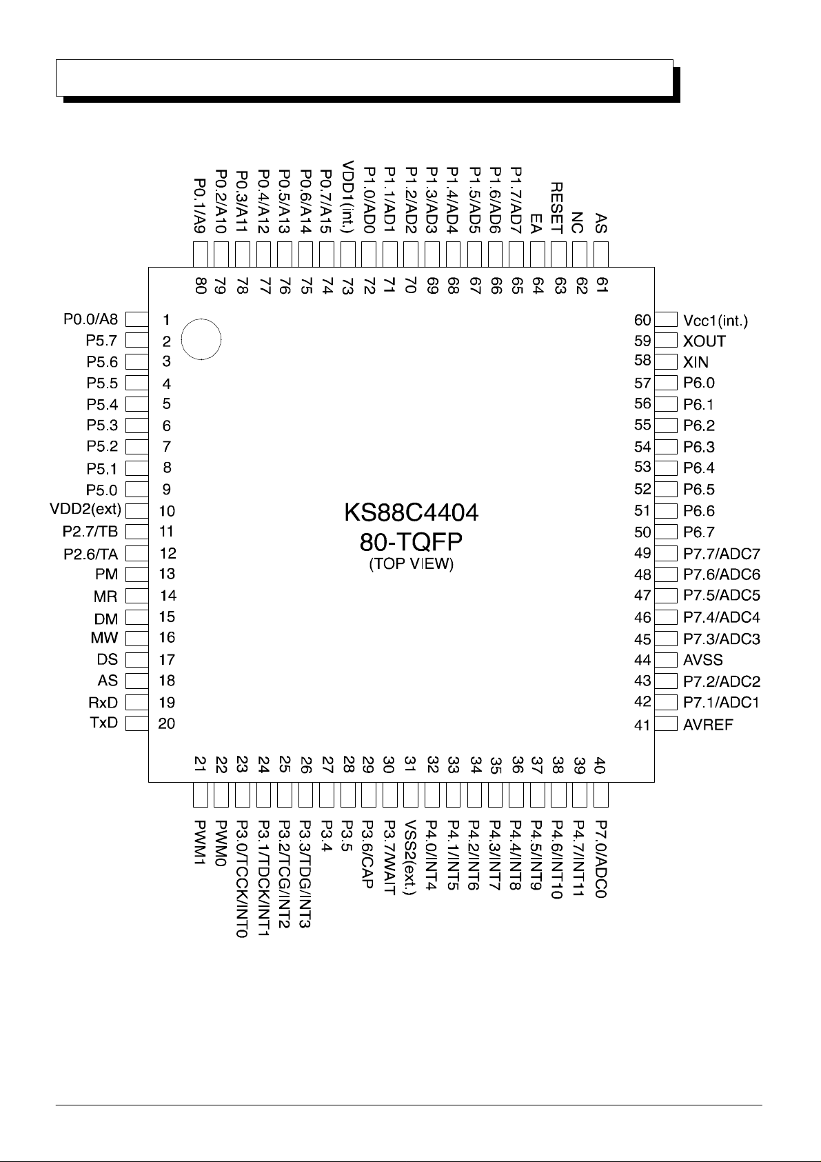
4. Main Components Block Diagram and Pin Descrip tions
¡Ü
KS88C4404 MICROCONTROLLER
Samsung Electronics
Figure 1-4. KS88C4404 Pin Assignments
3
¡Ü
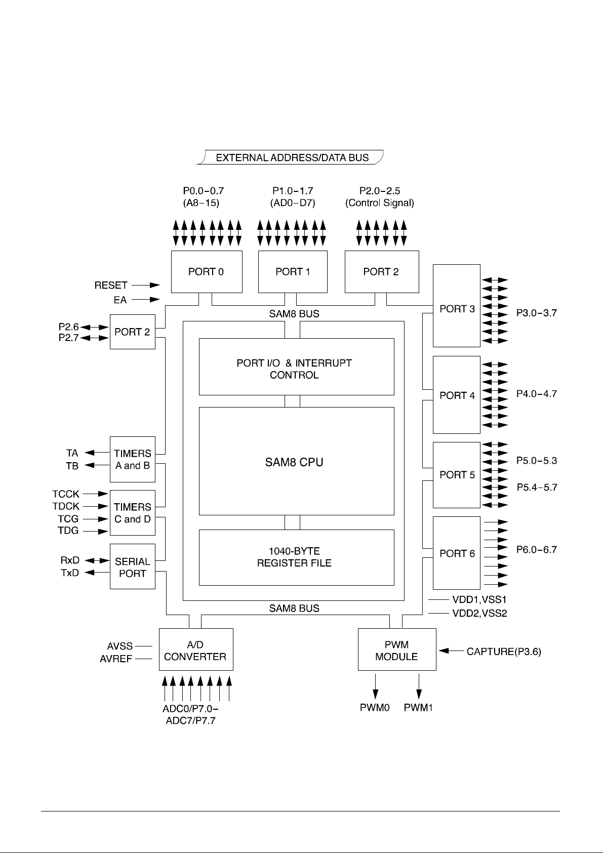
BLOCK DIAGRAM KS88C4404
Figure 1-2. KS88C4404 Block Diagram
4
Samsung Electronics

¡Ü
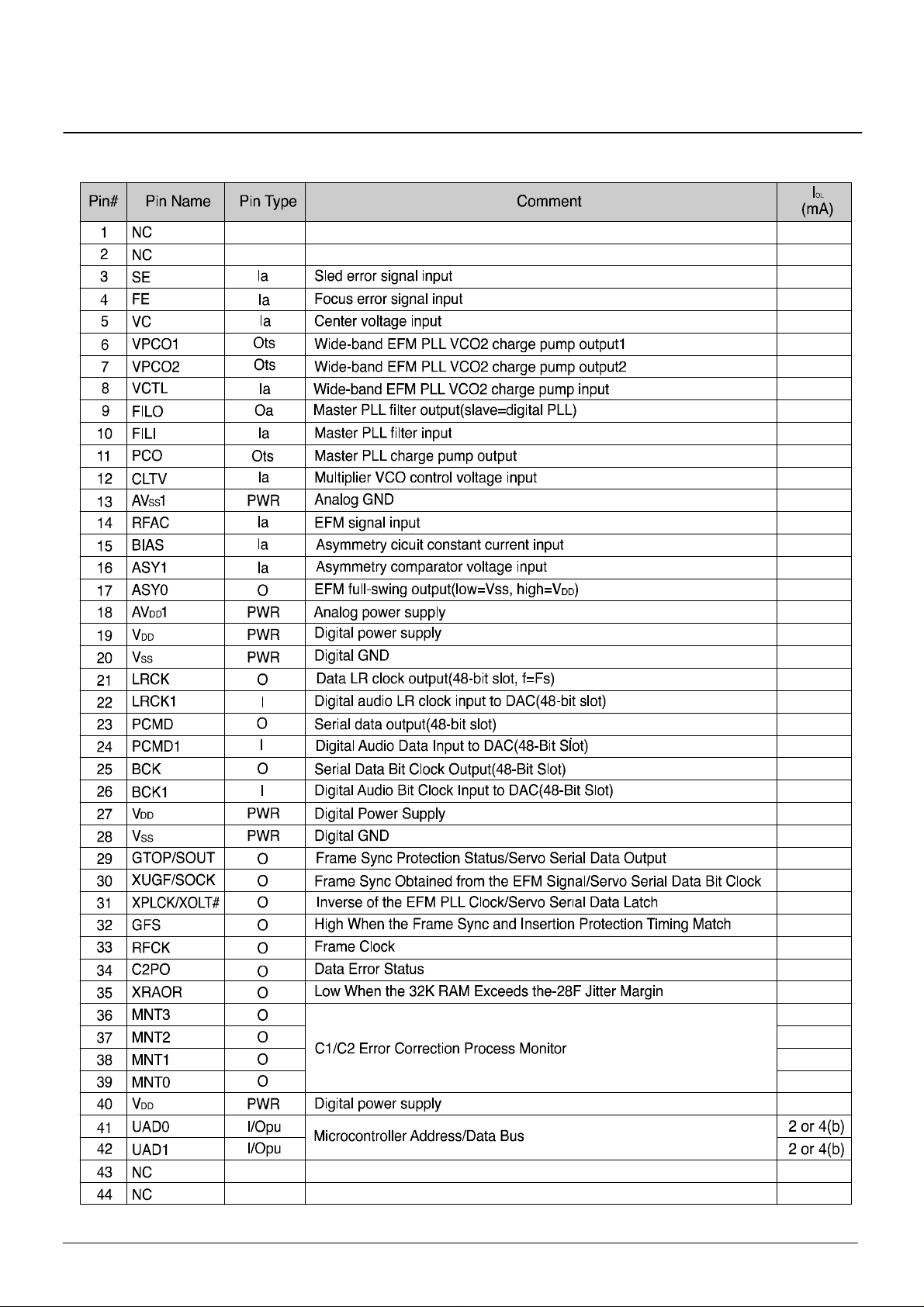
OTI 9230
OTI-9230 PIN DESCRIPTIONS
Samsung Electronics
5

¡Ü
OTI 9230
Figure 1-3. OTI-9230 Detailed Block Diagram
6
Samsung Electronics
OTI 9230
1. PIN-OUT ASSIGNMEN
Samsung Electronics
7
OTI-923 0 Pin Descriptions
PIN-OUT ASSIGNMENT(Cont'd)
8
Samsung Electronics

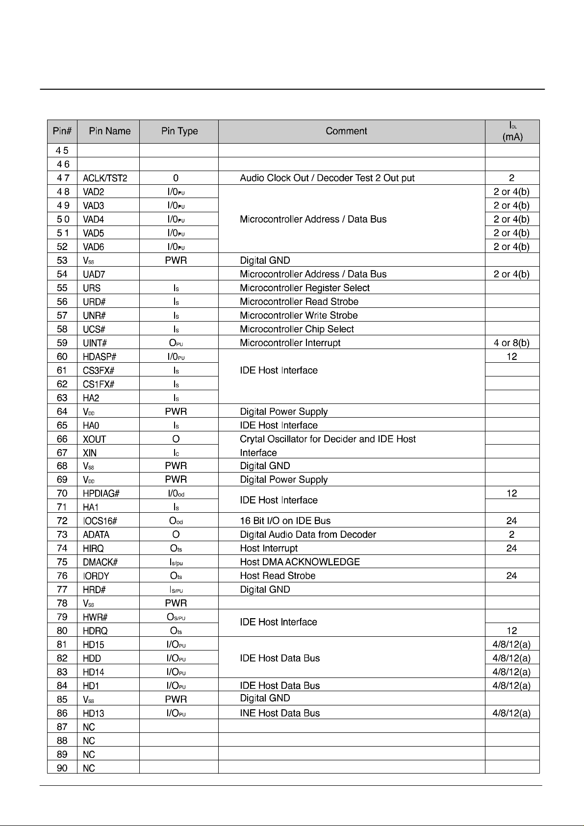
OTI-923 0
PIN-OUT ASSIGNMENT(Cont'd)
Pin Descriptions
Samsung Electronics
9

OTI-923 0
PIN-OUT ASSIGNMENT(Cont'd)
Pin Types:
PWR
Power
Input TTL
I
Input Analog
a
Input CMOS
c
Input Schmitt Trigger
s
Input Schmitt Trigger/Pull-Up Resistor
s/pu
Input Schmitt Trigger/Pull-Down Resistor
s/pd
l
I
I
I
I
O
O
Output
Output Open Drain
od
O
Output With Pull-up Resistor
pu
O
Output Three State
ts
O
Output with Pull-up Resistor/Three Sate
pu/ts
I/O
Bidirectional TTL With Pull-up Resistor
pu
Programmable-IOL Pins:
Pins with IOL=a are Group-a Programmable-IOL pins, with sink current controlled by register PWR0 bits 5 and
4(microcontroller address B0h).
Pins with IOL=b are Group-b Programmable-IOL pins, with sink current cdontrolled by register PWR0 6
(microcontroller address B0h).
10
Samsung Electronics
 Loading...