

Samsung VP-L980, VP-L320, VP-L330, VP-L300, SCL320 User Manual
...
© Samsung Electronics Co.,Ltd. MAR. 1999
Printed in Korea
AD68-00079B
SERVICE MANUAL
SCL300/L310/L320/L330/L350/L800/L850/VP-L300/L320/L330/L350/L980
8mm CAMCORDER
SCL300/L310/L320/L330/L350
SCL800/L850
VP-L300/L320/L330/L350
VP-L980
SERVICE
1. Precautions
2. Service Tips
3. Product Specifications and
Comparison Chart
4. Disassembly and Reassem
5. Alignment and Adjustment
6. Exploded View and Parts L
7. Electrical Parts List
8. PCB Diagrams
9. Wiring Diagram
10. Schematic Diagrams
Manua
8mm CAMCORDER
CONTENTS
For mechanical disassembly and adjustment, refer to the “Mechanical Manual”
(DE-6 AD68-30200A).
cover 5/11/95 9:42 AM Page 1
Samsung Electronics 1-1
1. Be sure that all of the built-in protective devices
are replaced. Restore any missing protective
shields.
2. When reinstalling the chassis and its assemblies, be sure to restore all protective devices,
including :
control knobs and compartment covers.
3. Make sure that there are no cabinet openings
through which people--particularly children
--might insert fingers and contact dangerous
voltages. Such openings include the spacing
between the picture tube and the cabinet mask,
excessively wide cabinet ventilation slots, and
improperly fitted back covers.
If the measured resistance is less than 1.0
megohm or greater than 5.2 megohms, an
abnormality exists that must be corrected
before the unit is returned to the customer.
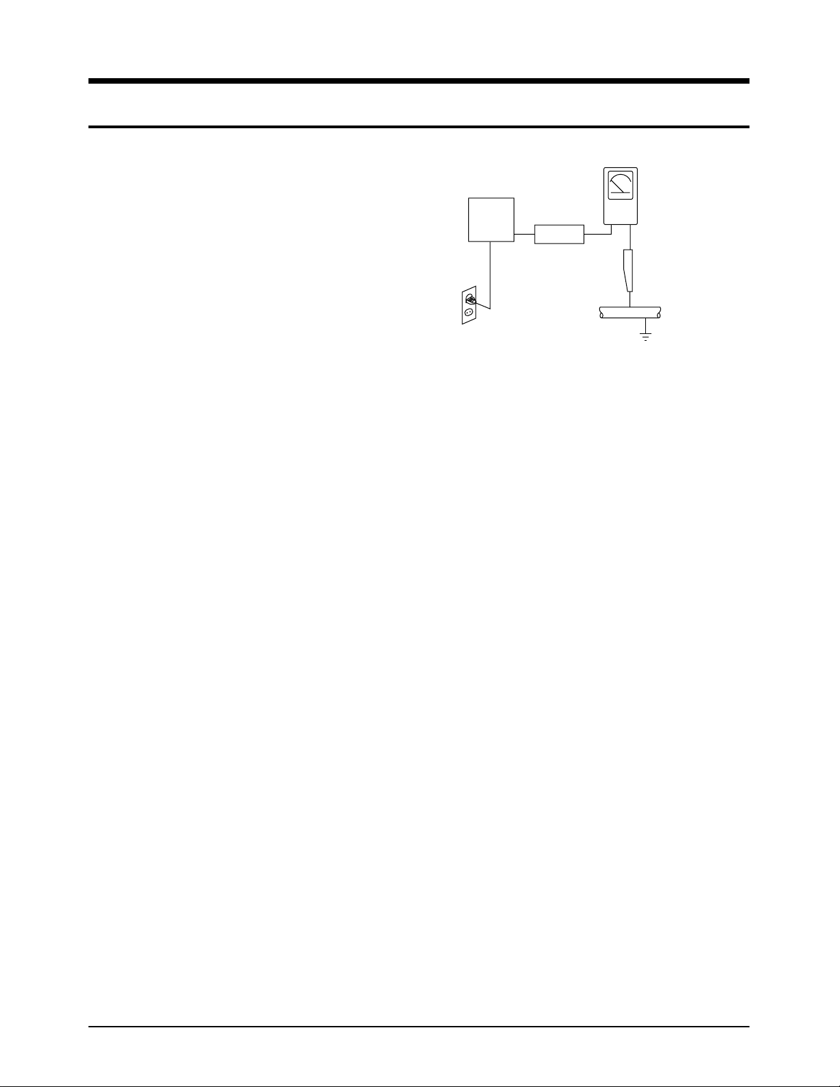
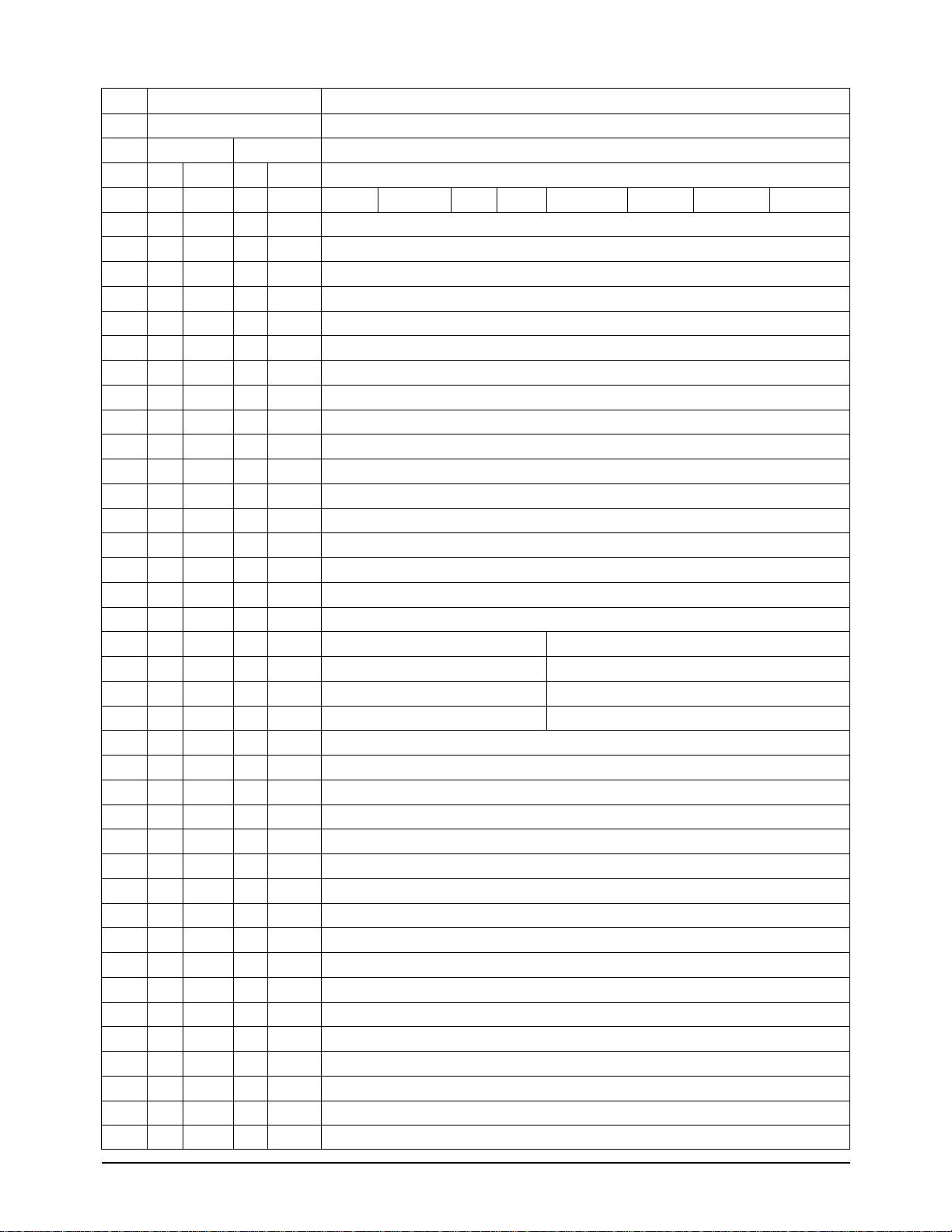
4. Leakage Current Hot Check (See Fig. 1) :
Warning : Do not use an isolation transformer
during this test. Use a leakage current tester or
a metering system that complies with American
National Standards Institute (ANSI C101.1,
Leakage Current for Appliances), and
Underwriters Laboratories (UL Publication
UL1410, 59.7).
5. With the unit completely reassembled, plug the
AC line cord directly the power outlet. With the
unit’s AC switch first in the ON position and
then OFF, measure the current between a
known earth ground (metal water pipe, conduit, etc.) and all exposed metal parts, including : antennas, handle
brackets, metal cabinets, screwheads and control shafts. The current measured should not
exceed 0.5 milliamp. Reverse the power-plug
prongs in the AC outlet and repeat the test.
6. X-ray Limits :
The picture tube is designed to prohibit X-ray
emissions. To ensure continued X-ray protection, replace the picture tube only with one that
is the same type as the original.
Fig. 1 AC Leakage Test
7. Antenna Cold Check :
With the unit’s AC plug disconnected from the
AC source, connect an electrical jumper across
the two AC prongs. Connect one lead of the
ohmmeter to an AC prong.
Connect the other lead to the coaxial connector.
8. High Voltage Limit :
High voltage must be measured each time
servicing is done on the B+, horizontal deflection or high voltage circuits.
Heed the high voltage limits. These include the
X-ray protection Specifications Label, and the
Product Safety and X-ray Warning Note on the
service data schematic.
9. Some semiconductor (“solid state”) devices are
easily damaged by static electricity.
Such components are called Electrostatically
Sensitive Devices (ESDs); examples include
integrated circuits and some field-effect transistors.
The following techniques will reduce the
occurrence of component damage caused by
static electricity.
10. Immediately before handling any semiconduc-
tor components or assemblies, drain the electrostatic charge from your body by touching a
known earth ground. Alternatively, wear a discharging Wrist-strap device. (Be sure to
remove it prior to applying power--this is an
electric shock precaution.)
1. Precautions
Device
Under
Test
(Reading should
not be above
0.5mA)
Leakage
Currant
Tester
Earth
Ground
Test all
exposed metal
surfaces
Also test with
plug reversed
(using AC adapter
plug as required)
2-Wire Cord

11. High voltage is maintained within specified
limits by close-tolerance, safety-related components and adjustments. If the high voltage
exceeds the specified limits, check each of the
special components.
12. Design Alteration Warning :
Never alter or add to the mechanical or electrical design of this unit. Example : Do not
add auxiliary audio or video connectors. Such
alterations might create a safety hazard. Also,
any design changes or additions will void the
manufacturer’s warranty.
13. Hot Chassis Warning :
Some TV receiver chassis are electrically
connected directly to one conductor of the AC
power cord. If an isolation transformer is not
used, these units may be safely serviced only
if the AC power plug is inserted so that the
chassis is connected to the ground side of the
AC source.
To confirm that the AC power plug is inserted
correctly, do the following : Using an AC
voltmeter, measure the voltage between the
chassis and a known earth ground. If the reading is greater than 1.0V, remove the AC power
plug, reverse its polarity and reinsert. Re-measure the voltage between the chassis and
ground.
14. Some TV chassis are designed to operate with
85 volts AC between chassis and ground,
regardless of the AC plug polarity. These units
can be safely serviced only if an isolation
transformer inserted between the receiver and
the power source.
15. Never defeat any of the B+ voltage interlocks.
Do not apply AC power to the unit (or any of
its assemblies) unless all solid-state heat sinks
are correctly installed.
16. Always connect a test instrument’s ground
lead to the instrument chassis ground before
connecting the positive lead; always remove
the instrument’s ground lead last.
17. Observe the original lead dress, especially near
the following areas : Antenna wiring, sharp
edges, and especially the AC and high voltage
power supplies. Always inspect for pinched,
out-of-place, or frayed wiring. Do not change
the spacing between components and the
printed circuit board. Check the AC power
cord for damage. Make sure that leads and
components do not touch thermally hot parts.
18. Picture Tube Implosion Warning :
The picture tube in this receiver employs
“integral implosion” protection. To ensure
continued implosion protection, make sure
that the replacement picture tube is the same
as the original.
19. Do not remove, install or handle the picture
tube without first putting on shatterproof goggles equipped with side shields. Never handle
the picture tube by its neck. Some “in-line”
picture tubes are equipped with a permanently
attached deflection yoke; do not try to remove
such “permanently attached” yokes from the
picture tube.
20. Product Safety Notice :
Some electrical and mechanical parts have
special safety-related characteristics which
might not be obvious from visual inspection.
These safety features and the protection they
give might be lost if the replacement component differs from the original--even if the
replacement is rated for higher voltage,
wattage, etc.
Components that are critical for safety are
indicated in the circuit diagram by shading,
( or ).
Use replacement components that have the
same ratings, especially for flame resistance
and dielectric strength specifications.
A replacement part that does not have the
same safety characteristics as the original
might create shock, fire or other hazards.
Samsung Electronics1-2
Precautions

Samsung Electronics 2-1
✤ The Service materials (Lamp, Plier) will be supplied by SEC Korea.
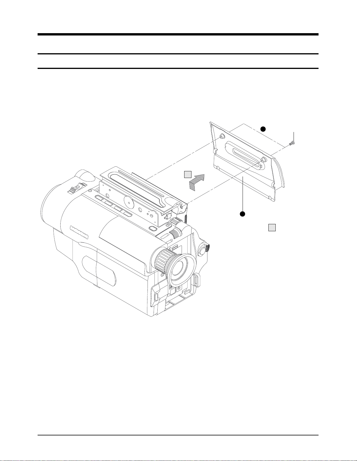
1. Disassemble the screw from the camcorder with a
small screw driver as figure.
2. Pull out the video light cover unit carefully as figure.
❚ Do not apply excessive force because the cover is
easy to be broken.
❚ The right side of the cover is fixed by hitch, and the
left by a screw.
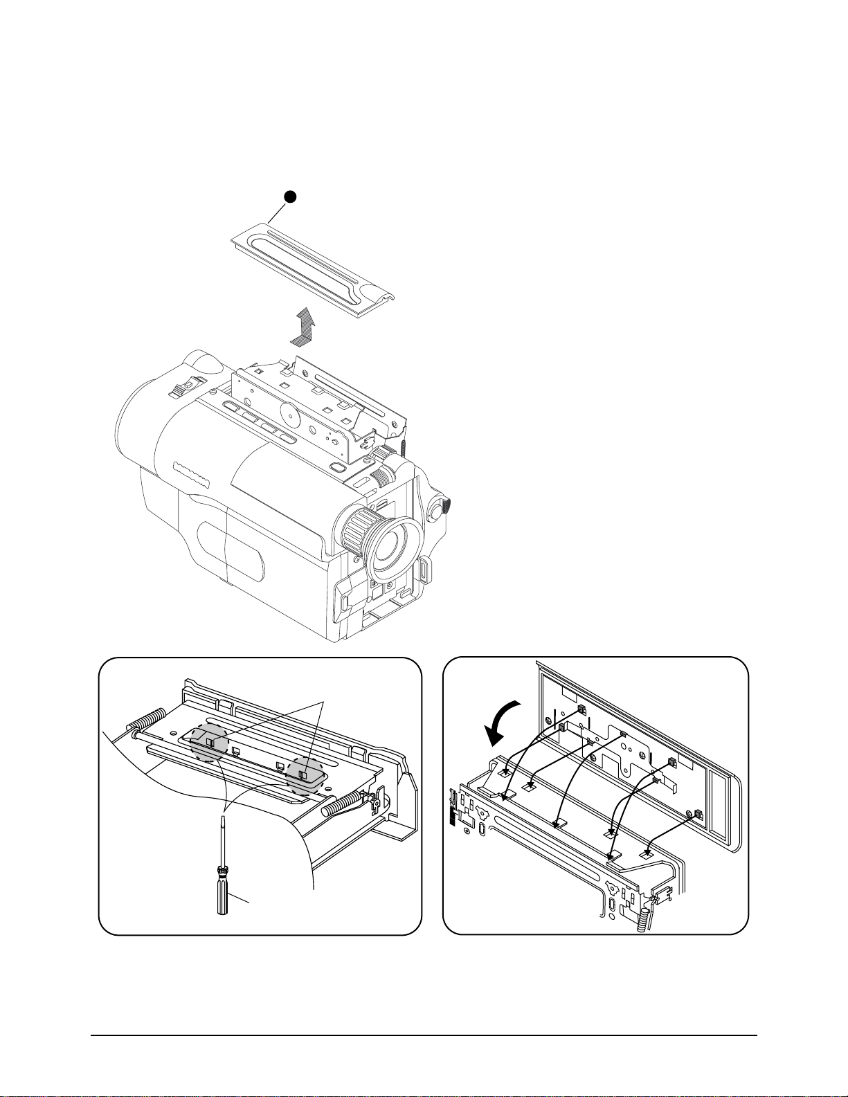
3. Pull out the bulb with flat pliers supplied as a service
tool.
❚ Do not apply excessive force because the cover is
easy to be broken.
4. Insert a new BULB(JC 6V-3W/G2.5) with a pliers as
figure.
❚ Do not apply excessive force because the cover is
easy to be broken.
❚ Make sure that the bulb is in place exactly.
❚ To prevent the smudge of the finger prints reducing
the life of the bulb, do not touch the bulb with fingers.
5. Reassemble the video light cover unit to the camcorder carefully as figure.
❚ Do not apply excessive force because the cover is
easy to be broken.
6. Reassemble the screw with a small screw driver to
the camcorder.
2. Service Tip
2-1 Replacing The Bulb For The Video Light
1
2
3
4
5
6

Samsung Electronics2-2
Service Tips
MEMO
MEMO
Samsung Electronics 3-1
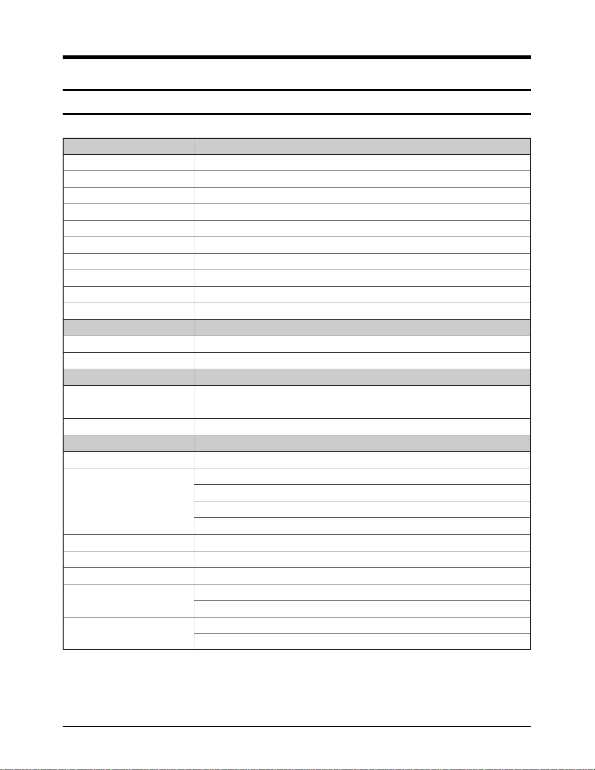
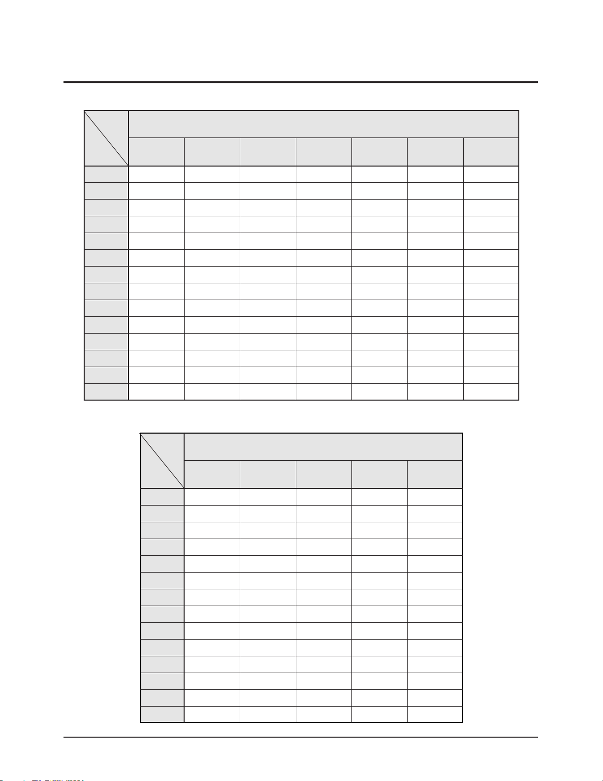
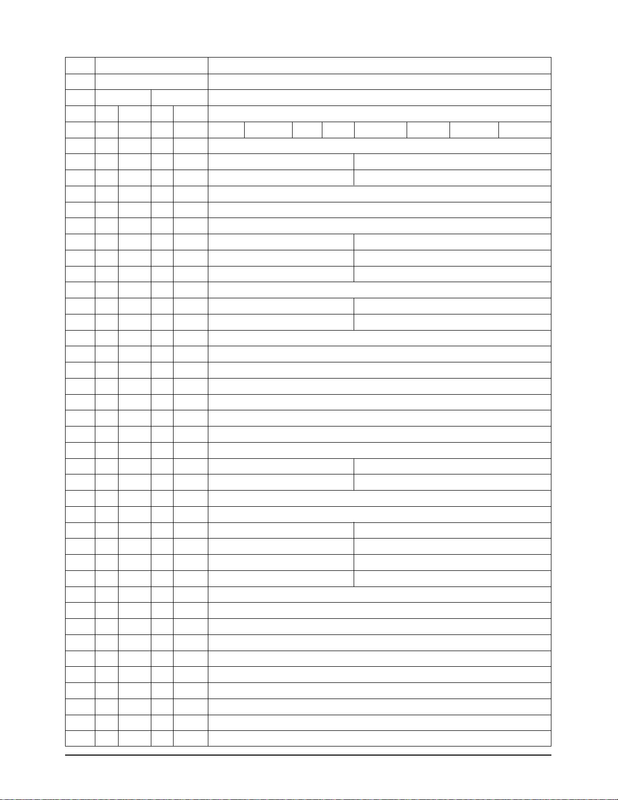
3. Product Specifications and Comparison Chart
3-1 NTSC Models (SCL300/L310/L320/L330/L350/L800/L850)
System SCL300/L310/L320/L330/L350/L800/L850
Recording time P6-120: 120 min.
FF or REW time P6-120: approx. 6.5 min.
Image device CCD (Charge Coupled Device)
Optical zoom ratio SCL300/L310/L320/L330: 16X, SCL350/L800/L850:22X
Focal length:f SCL300/L310/L320/L330: 3.9~62.6 mm, SCL350/L800.L850: 4.0~88.0 mm
F SCL300/L310/L320/L330: 1.4, SCL350/L800/L850: 1.6
Filter diameter 46 mm
Focus system Inner
Macro Auto wide macro
Min. Illumination 0.3 lux (visible)
LCD monitor
Size/Pic. cell SCL300/L310/L320: 2.5 inch/62k, SCL330/L350/L800/L850: 3 inch/89k
Method TFT
Connectors
Video out Mini jack, 1 Vp-p, 75 ohms, Unbalanced
Audio out Mini jack, 7.7 dBs, imp.: less than 2.2 kohms
External mic Monaural (SCL800/L850: stereo), ø3.5
General
Power requirement 6.0~7.2 V DC
Power consumption SCL300/L310: 5.3 W,
SCL320: 5.4 W, SCL330: 5.6 W
SCL350: 5.7 W
SCL800: 6.1 W, SCL850: 6.2 W
Built-in mic Condenser mic, omni-directional
Built-in speaker Dynamic, 0.5 W standard
Operating temperature 0°C to 40°C (32°F to 104°F)
Dimension (WXHXD) SCL300/L310/L320/L330 : 109X104X215 mm (4.29X4.09X8.46 inch)
SCL350/L800/L850 : 109X104.5X221mm (4.29X4.09X8.7 inch)
Weight SCL300/L310/L320 : 860 g (1.89 lbs), SCL330 : 870 g (1.92 lbs)
SCL350 : 900 g (1.98 lbs), SCL800/L850 : 900 g (1.98 lbs)
✤ The technical specifications and design may be changed without notice.
*Conditions:
LCD on/EVF off/EIS off/LIGHT off
Recording
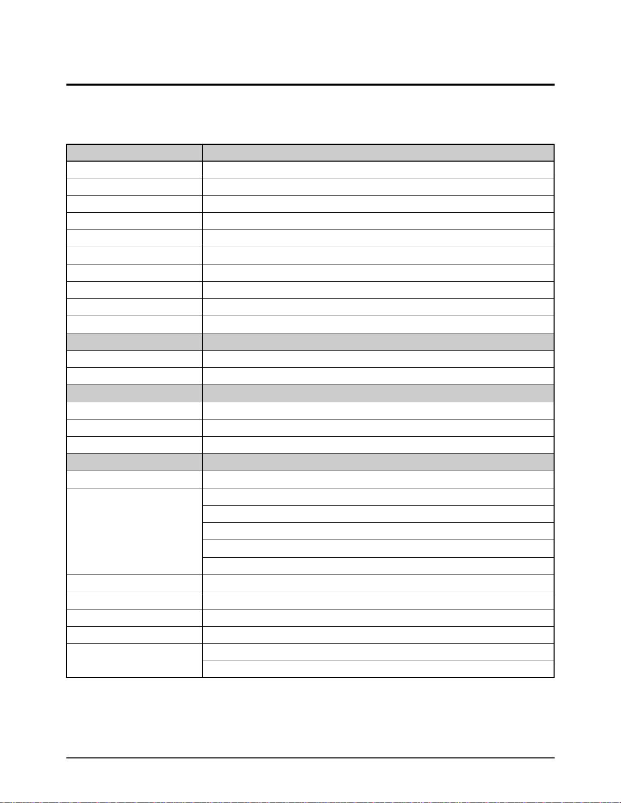
System VP-L300/L320/L330/L350/L980
Recording time P5-120: 120 min.
FF or REW time P5-120: approx. 8 min.
Image device CCD (Charge Coupled Device)
Optical zoom ratio VP-L300/L320/L330: 16X, VP-L350/L980:22X
Focal length:f VP-L300/L320/L330: 3.9~62.6 mm, VP-L350/L980: 4.0~88.0 mm
F VP-L300/L320/L330: 1.4, VP-L350/L980: 1.6
Filter diameter 46 mm
Focus system Inner
Macro Auto wide macro
Min. Illumination 0.3 lux (visible)
LCD monitor
Size/Pic. cell VP-L300/L320: 2.5 inch/62k, VP-L330/L350/L980: 3 inch/89k
Method TFT
Connectors
Video out Mini jack, 1 Vp-p, 75 ohms, Unbalanced
Audio out Mini jack, 7.7 dBs, imp.: less than 2.2 kohms
External mic Monaural (VP-L980: stereo), ø3.5
General
Power requirement 6.0~7.2 V DC
Power consumption VP-L300: 5.3 W
VP-L320: 5.4 W
VP-L330: 5.6 W
VP-L350: 5.7 W
VP-L980: 6.2 W
Built-in mic Condenser mic, omni-directional
Built-in speaker Dynamic, 0.5 W standard
Operating temperature 0°C to 40°C (32°F to 104°F)
Dimension (WXHXD) VP-L300/L320/L330 : 109X104X215, VP-L350/L980 : 109X104.5X221
Weight VP-L300/L320 : 860 g, VP-L330 : 870 g
VP-L350 : 900 g, VP-L980 : 900 g
Samsung Electronics3-2
Product specifications and comparison chart
3-2 PAL Models (VP-L300/L320/L330/L350/L980)
✤ The technical specifications and design may be changed without notice.
*Conditions:
LCD on/EVF off/EIS off/LIGHT off
Recording
Hi8 mm
3´´
O
O
O
O
O
Ni-MH
Stereo
B & W
O
Auto
x22 (x440)
570 K
8 mm
3´´
O
O
O
O
O
Ni-MH
Mono
B & W
O
Auto
x22 (x440)
570 K
8 mm
3´´
X
X
O
O
O
Ni-MH
Mono
B & W
O
Auto
x16 (x320)
320 K
8 mm
2.5´´
X
X
X
O
O
Ni-Cd
Mono
B & W
O
Auto
x16 (x320)
320 K
NTSC
Features
Format
LCD Size
V/Light
EIS
XDR
BLC
Remocon
Battery
Audio
V/Finder
P.Title
Focus System
Z/Ratio
CCD
Model
Features
Samsung Electronics 3-3
Product specifications and comparison chart
3-3 Comparison Chart
Format
LCD Size
V/Light
EIS
I-BLC
BLC
Remocon
Battery
Audio
V/Finder
P.Title
Focus System
Z/Ratio
CCD
8 mm
2.5´´
X
X
X
O
X
Ni-Cd
Mono
B & W
O
Auto
x16 (x320)
270 K
8 mm
2.5´´
X
X
X
O
O
Ni-MH
Mono
B & W
O
Auto
x16 (x220)
270 K
8 mm
2.5´´
X
O
X
O
O
Ni-Cd
Mono
B & W
O
Auto
x16 (x320)
270 K
8 mm
3´´
X
X
O
O
O
Ni-MH
Mono
B & W
O
Auto
x16 (x320)
270 K
8 mm
3´´
O
O
O
O
O
Ni-MH
Mono
B & W
O
Auto
x22 (x440)
270 K
Hi8 mm
3´´
X
X
O
O
O
Ni-MH
Stereo
B & W
O
Auto
x22 (x440)
470 K
Hi8 mm
3´´
O
O
O
O
O
Ni-MH
Stereo
B & W
O
Auto
x22 (x440)
470 K
8 mm
2.5´´
X
O
O
O
O
Ni-Cd
Mono
B & W
O
Auto
x16 (x320)
320 K
SCL300 SCL310 SCL320 SCL330 SCL350 SCL800 SCL850
VP-L300 VP-L320 VP-L330 VP-L350 VP-L980
Model
PAL

Samsung Electronics3-4
Product specifications and comparison chart
MEMO
MEMO
Samsung Electronics 4-1
4. Disassembly and Reassembly
4-1 Cabinet Disassembly
4-1-1 Ass’y Cover Housing Removal
1
Remove 2 screws.
2
Remove the ass'y cover
housing in the direction
of arrow .
A
A
Fig. 4-1 Ass’y Cover Housing Removal
*
It is recommended to eject the cassette
housing for removal the cover housing.
*
You don’t need to disassemble the Cover
Housing except that you change the Deck
Mechanism.
Samsung Electronics4-2
Disassemblr and Reassembly
4-1-2 Ass’y Case Top Removal
1
Remove ass'y case top by gentlely releasing
2 locking tabs with a small screw driver.
(see DETAIL "A")
REASSEMBLY : Put the 7 tabs into the slot,
while sliding it as shown in DETAIL "B".
2 locking tabs
Precision screw driver
< DETAIL "A" >
"B"
< DETAIL "B" >
Fig. 4-2 Ass’y Case Top Removal
*
You don’t need to disassemble the Case Top except that
you change the Deck Mechanism.
Samsung Electronics 4-3
Disassemblr and Reassembly
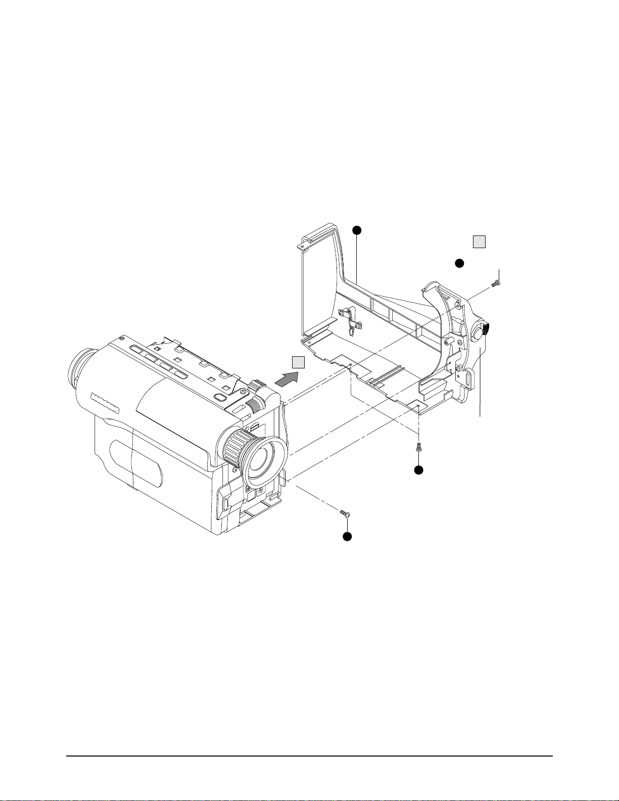
1
1
1
Remove 4 screws.
3
Disconnect the FPC
or wire from the audio block
of MAIN PCB.
(Ass'y front for
EIS models)
(Ass'y front for
Non-EIS models)
2
Pull out the ass'y front in
the direction of arrow , .
B
A
A B
4-1-3 Ass’y Front Removal
Fig. 4-3 Ass’y Front Removal
Samsung Electronics4-4
Disassemblr and Reassembly
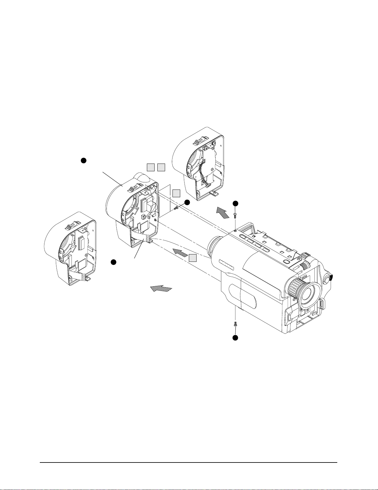
4-1-4 Ass’y Case Right Removal
1
Remove 4 screws.
Pull out the unit case
in the direction of arrow .
Disassemble after turning
knob to be "LOCK".
1
1
2
A
A
Fig. 4-4 Ass’y Case Right Removal
Samsung Electronics 4-5
Disassemblr and Reassembly
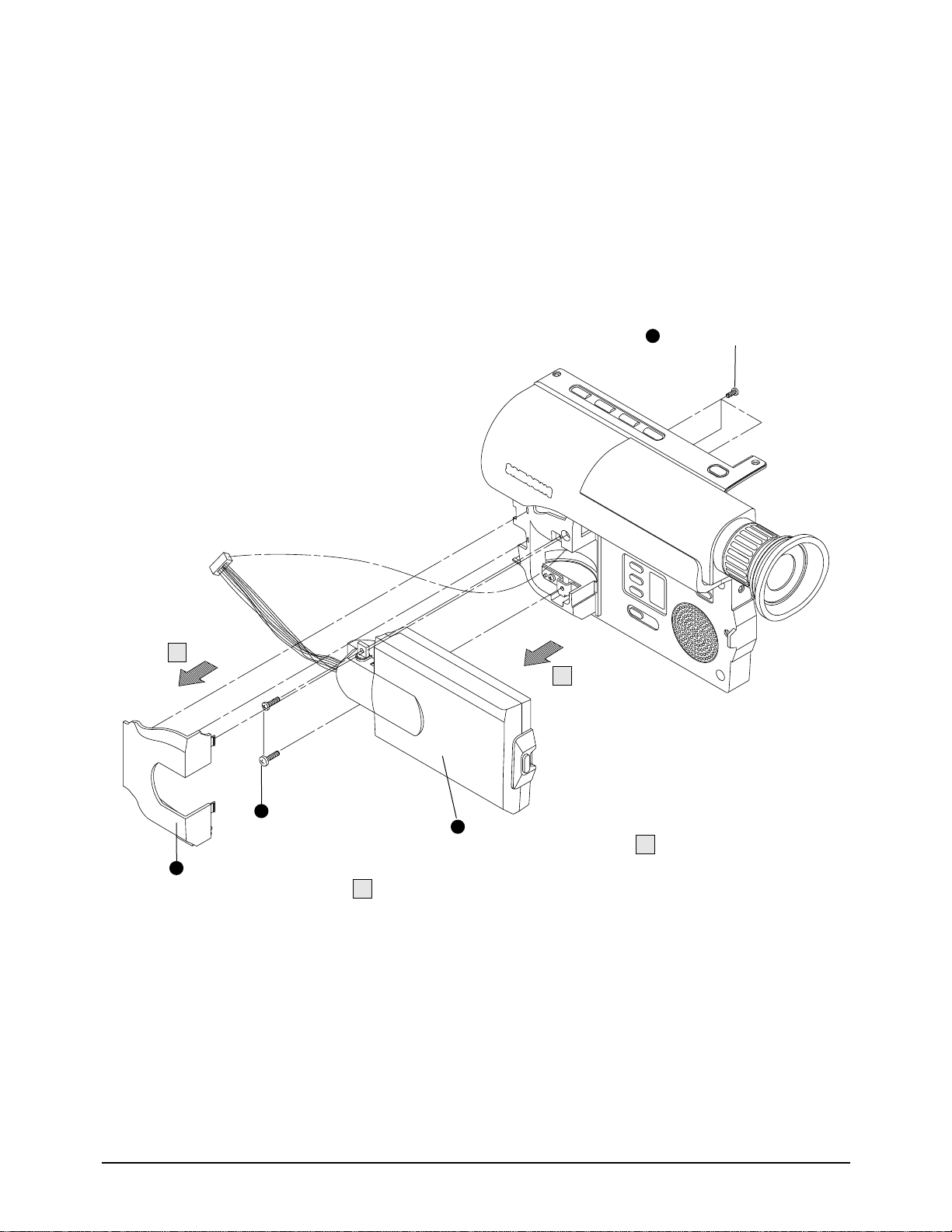
2
Pull out the case left
assembly in the direction
of arrow .
1
1
Remove 5 screws.
1
1
1
A
A
Disconnect wire
of 15 pins.
Disconnect wire
of 10 pins.
4-1-5 Ass’y Case Left Removal
Fig. 4-5 Ass’y Case Left Removal
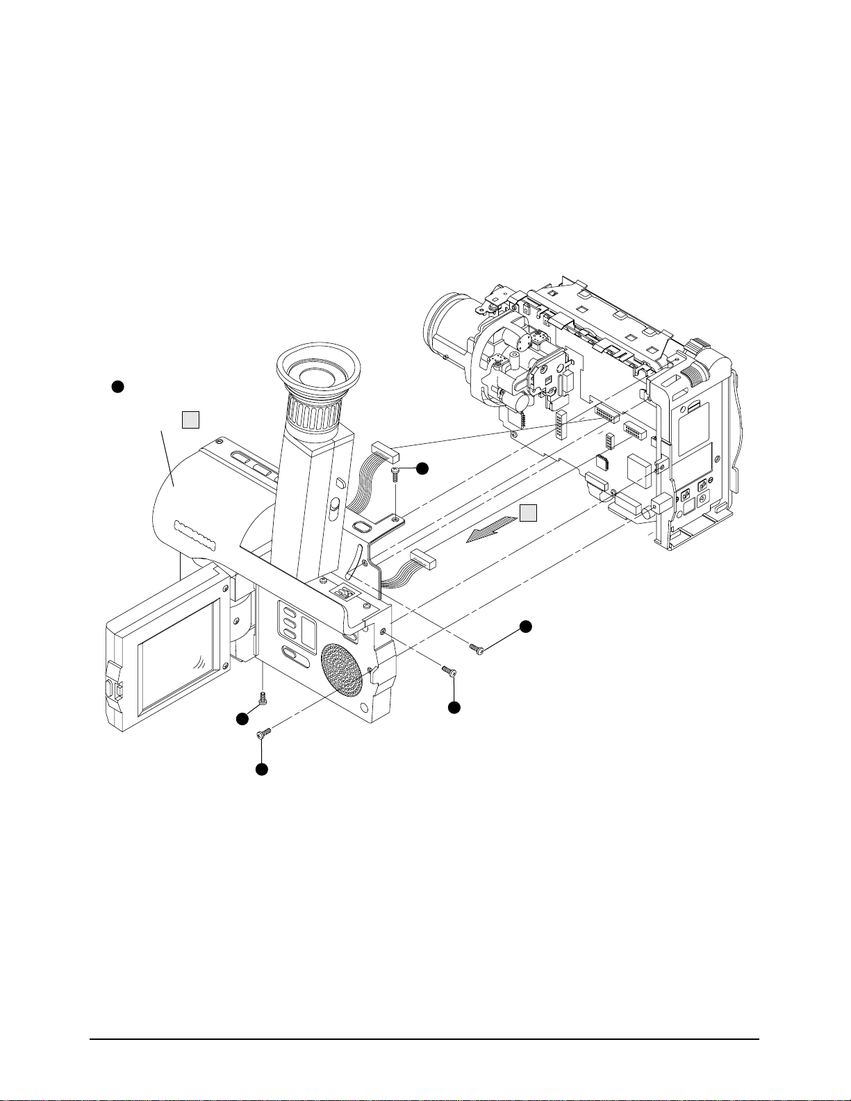
4
Pull out the LCD assembly
in the direction of arrow .
1
Remove 1 screw.
Remove 2 screws.
3
Pull out the cover
in the direction of arrow .
2
B
B
A
A
Samsung Electronics4-6
Disassemblr and Reassembly
Fig. 4-6 Ass’y LCD Removal
4-1-6 Ass’y LCD Removal
Samsung Electronics 4-7
Disassemblr and Reassembly
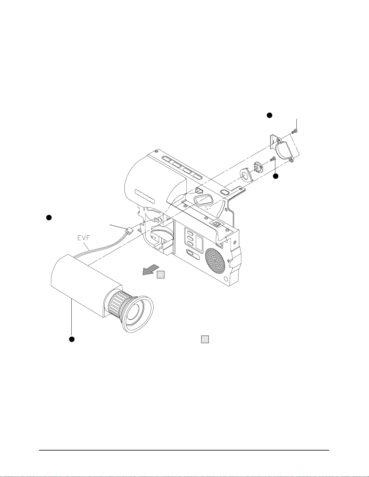
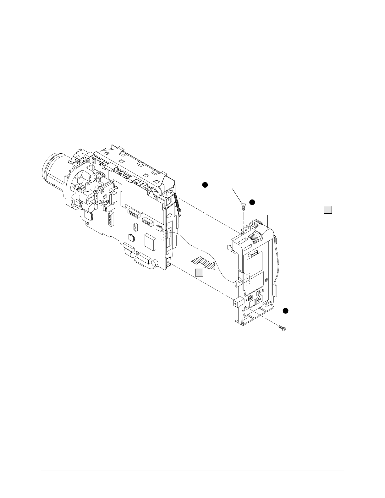
4-1-7 Ass’y EVF Removal
1
Remove 2 screws.
A
A
Remove 1 screw.
4
Pull out the EVF ass'y in the direction of arrow .
2
Disconnect wire of 3 pins from
the FUNCTION PCB.
3
Fig. 4-7 Ass’y EVF Removal
Samsung Electronics4-8
Disassemblr and Reassembly
1
Remove 1 screw.
A
A
2
Remove 1 screw.
3
Pull out the ass'y REAR board
in the direction of arrow .
4-1-8 Ass’y Rear Board Removal
Fig. 4-8 Ass’y Case Rear Removal
Samsung Electronics 4-9
Disassemblr and Reassembly
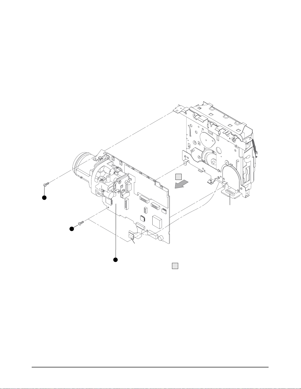
4-1-9 Ass’y 8mm Deck Removal
1
1
Remove 3 screws.
2
Pull out the MAIN PCB from the ass'y DECK
in the directiob of arrow .
A
A
Disconnect connector
from the MAIN PCB.
Disconnect connector
from the Head-Drum.
Fig. 4-9 Ass’y 8mm Deck Removal

Samsung Electronics4-10
Disassemblr and Reassembly
1
2
Remove 2 screws.
A
A
4
Disconnect connector and pull out the
ass'y LENS in the direction of arrow .
3
Disconnect FPC from the connector of the MAIN PCB.
Remove solder with an iron
to isolate PCB and LENS.
4-1-10 Ass’y Camera Removal
Fig. 4-10 Ass’y Camera Removal
Samsung Electronics 4-11
Disassemblr and Reassembly
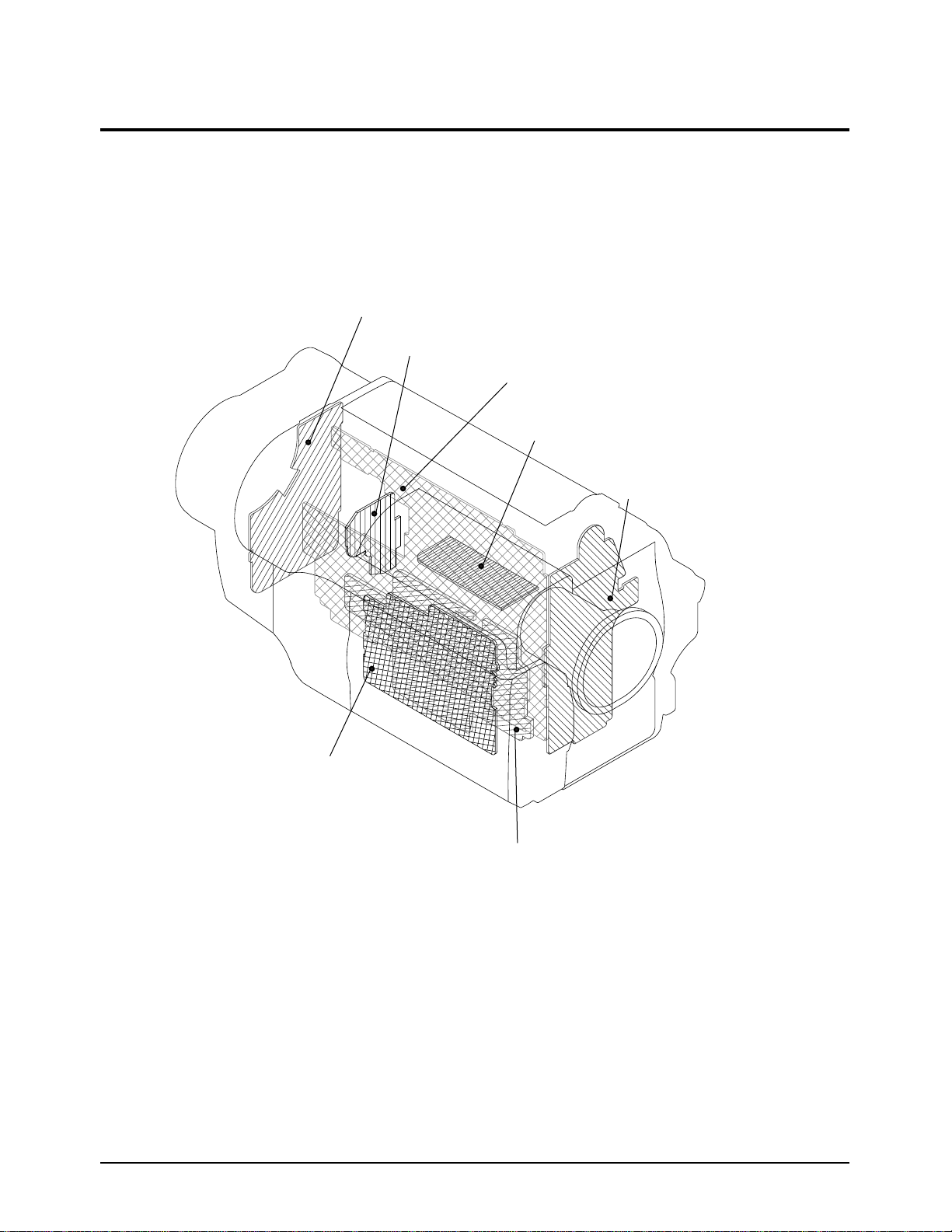
4-2 Circuit Boards Location
ASS'Y MAIN BOARD
ASS'Y CCD BOARD
ASS'Y LCD BOARD
ASS'Y FUNCTION BOARD
ASS'Y EVF BOARD
ASS'Y REAR BOARD
ASS'Y EIS BOARD (EIS MODEL)
ASS'Y FRONT BOARD (NON EIS MODEL)
Fig. 4-11 Circuit Boards Location
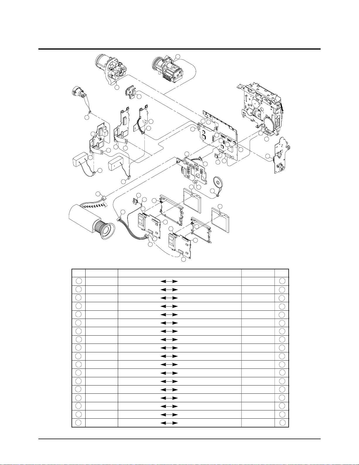
DIRECTION
DECK MAIN PCB
DECK MAIN PCB
MAIN PCB REAR PCB
MAIN PCB FUNCTION PCB
MAIN PCB LCD
MAIN PCB CCD PCB
MAIN PCB LENS FPC
MAIN PCB LENS FPC
MAIN PCB FRONT FFC (EIS,STEREO)
MAIN PCB FRONT FFC (EIS, MONO)
MAIN PCB FRONT PCB (NO EIS)
FRONT PCB MIC ASS’Y
FRONT PCB MIC ASS’Y
FRONT PCB MIC ASS’Y
FRONT PCB LIGHT ASS’Y
FUNCTION PCB EVF
FUNCTION PCB SPEAKER
LCD HINGE
1
2
3
4
5
6
7
8
9
10
11
12
13
14
15
16
17
18
19
20
21
23
24
25
26
27
28
29
30
31
32
33
34
35
36
37
37
38
39
40
41
42
43
44
Samsung Electronics4-12
Disassemblr and Reassembly
NO. NO.
4-3 Connector Diagrams
Fig. 4-12 Connector Diagrams
CONNECTOR
CN51
––
CN601
CN603
CN604
CNP01
CNP03
CNP02
CNP801
CN801
CN802
CN891
CN893
CN893
CN895
CN472
CN473
––
CONNECTOR
CN501
CN52
CN771
––
––
CNC01
––
––
CN894
CN894
CN890
––
––
––
––
––
––
––
1
357
9
111313
16
16
19
21
23
252628
38
31
2
468
10
12
14
15
17
18
20
22
242527
29
39
30
Samsung Electronics 5-1
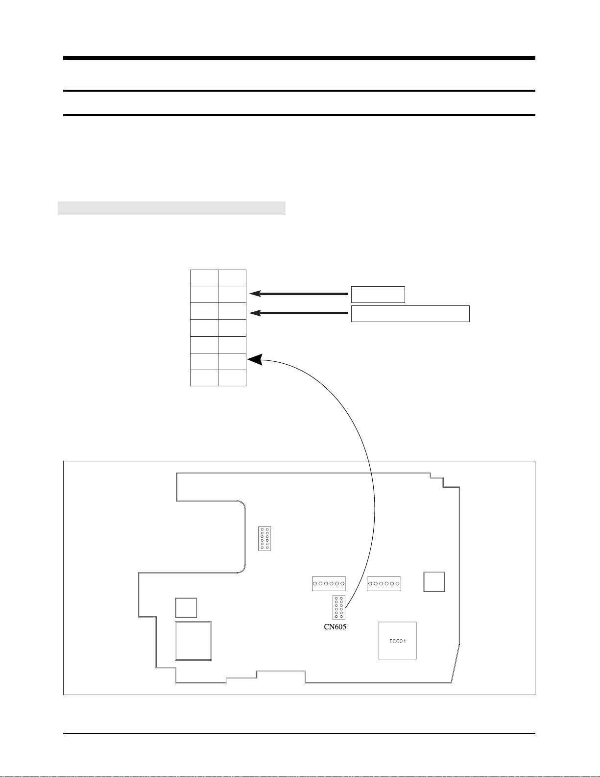
5. Alignment and Adjustment
5-1. Mechanism Alignment
¥ Refer to mechanical manual ÒDE-6 (AD68-30200A)Ófor the adjustment and checks of mechanism section.
Test Points for Mechanism Alignment
1. PB RF - Pin 11 of CN605
2. Head Switching (Trigger) - Pin 9 of CN605
14
12
10
8
6
4
2
13
11
9
7
5
3
1
PB RF
Head Switching - Trigger
CN605
Fig. 1 Test point
Fig. 2 Test location of test point

Samsung Electronics5-2
Alignment and Adjustment
POSITION
IC601 IC601 IC601
ACTION MODE
28PIN 27PIN 26PIN
L H H EJECT
L L H UNLOADING STOP
H L L LOADING STOP
H H L PLAY, FF, Z/RTN, STILL....
EJECT
UNLOADING STOP
LOADING STOP
PB
IC601
27PIN
GROUND
IC601
26PIN
COMMON
IC601
28PIN
OPEN
EJECT
PLAY
LOADING
STOP
UNLOADING
STOP
LOADING
UNLOADING
Reference
¥ Mechanical Transition Chart of MODE switch.

Samsung Electronics 5-3
Alignment and Adjustment
5-2 Camera Section Adjustment
Note :
1. This system has
1) EEPROM to store the confirmed adjustment data.
2) DSP (Digital Signal Process ; ICP01 - Main board) chip to process the signal of camera parts.
3) One test point for the frequency adjustment of DSP main clock (P. CLK).
4) The special mode for camera adjustment using the function keys on the left case.
2. Keep in mind
1) All adjustment steps should performed using the remote controller.
5-2-1 Preparations
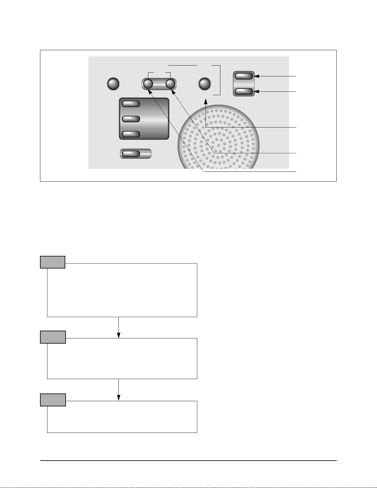
4. The function keys on the left case
The following is a chart explaining the use of each button :
1. Equipment to be used
1) DC Power supply
2) Oscilloscope
3) Frequency counter
4) Vectorscope
5) Waveform monitor
6) Color monitor or TV
7) Various charts
- Color bar chart
- Gray-scale chart, etc...
2. Composition of camera P.C.Boards
1) Main PCB
2) CCD PCB
3) EVF PCB
4) LCD PCB
3. Adjustment preparations
1) The function keys on the left case is used as a
camera adjust tool.
2) Press the confirm button when each manual
adjustment step is completed to write the
adjustment data to the EEPROM.
3) After each adjustment step is completed, OSD
shows ÒOK!Ó.
4) To cancel the adjustment mode, remove the
power source.
Using Button
MENU/ENTER (CONFIRM)
EDIT – (DATA DOWN)
EDIT + (DATA UP)
TITLE (MODE UP)
DATE/TIME (MODE DOWN)
MF
(FAR/NEAR)
ZOOM TELE/ZOOM WIDE
Adjustment
Data store after finishing adjustment by DATA UP/DOWN button.
When change data value of adjust state.
Mode change.
Manual focus adjustment.
Move the zoom position of lens.
Samsung Electronics5-4
Alignment and Adjustment
The function keys left case is required to adjust the camera section.
✤ ZOOM LEVER : ZOOM TELE/WIDE
Note : In service adjustment mode, button names are different from those in customer camera function con-
trol mode. EX) MENU/ENTER button is the same as confirm.
5. How to get into service ÒADJUSTÓ mode
1. Remove the lithium battery from the camcorder.
2. Connect the power source (battery/DC cable).
3. Eject the tape if it is in the unit.
4. Set the power switch of the camcorder to “CAMERA” position.
5. Set OSD on state.
STEP 1
1. Press and hold the “EJECT” button and “STOP”
button on the camcorder at the same time for
more than 5 seconds.
Then unit goes into service mode.
STEP 2
On screen display show “ODF. T.INI XX XX” CAMERAADJUSTMENT mode has successfully been
activated.
STEP 3
Note : When ÒXX XXÓ is shown in service adjustment procedures, this indicates variable values.
DATA DOWN
DATA UP
MODE DOWN
MODE UP
CONFIRM
ZERO RETURN
XDR/BLC
SELECT MENU
EDIT
_
DSE
ON/OFF
COUNTER
RESET
DISPLAY
+
ENTER
TITLE
DATE/TIME
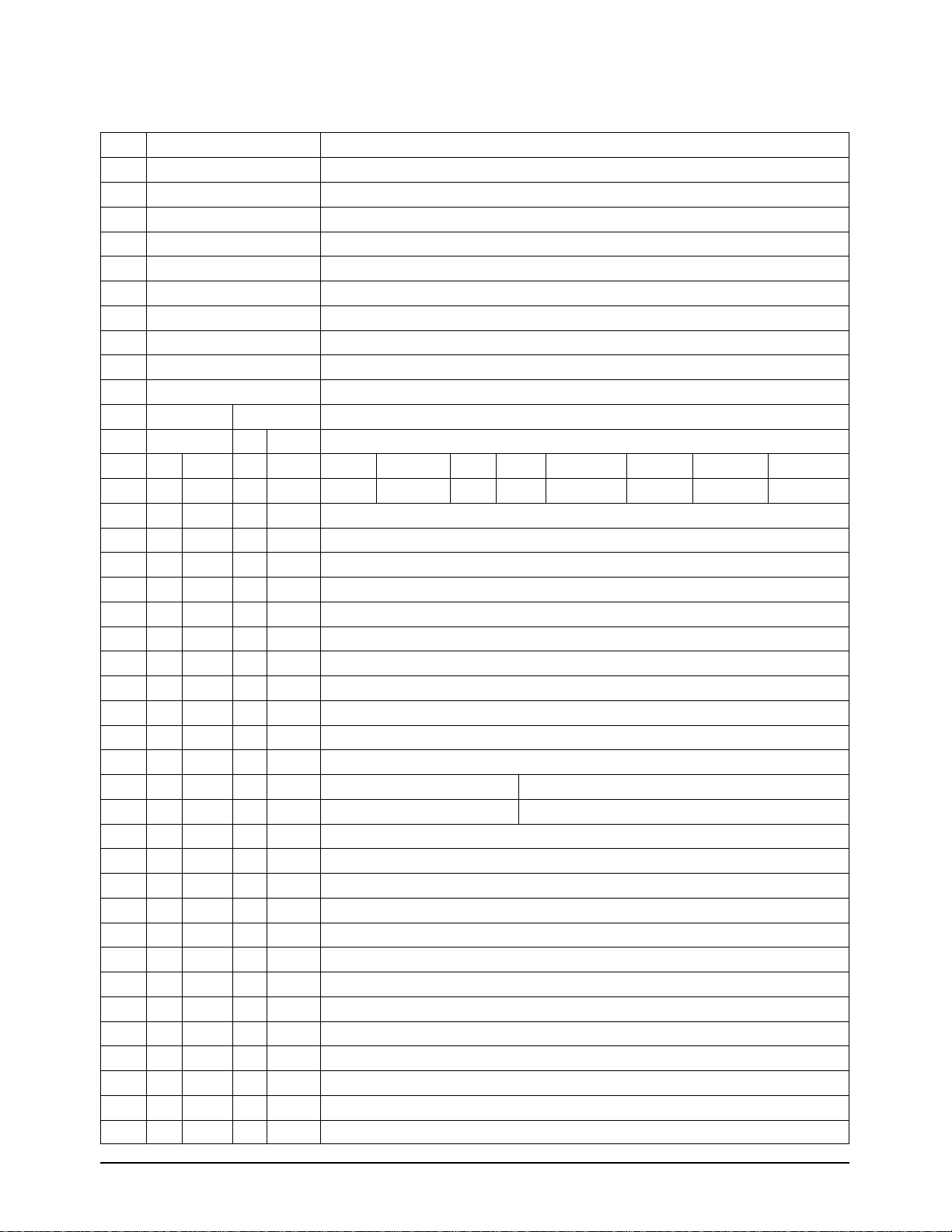
ADDR OSD-DISPLAY CONTENT
0DF T.INI TABLE INITIAL
0CD HALL HALL AUTO ADJUST
0CE IRIS IRIS AUTO ADJUST
0CF AWB AWB AUTO ADJUST
0D0 LENS LENS AUTO ADJUST( WARNING! DONÕT USE WITHOUT AN INFINITE COLLIMATOR)
0D6 ZVR.C ZOOM LEVER CENTER DATA CHECKING
0DB AGCM AGC AUTO ADJUST (NORMALLY NO USED)
0DE 3MLENS 3M LENS AUTO ADJUST AT SERVICE FIELD (DISTANCE: 3M +/- 1Cm)
NO-OSD-DISPLAY
ADDR MODEL/DATA CONTENT (EEPROM DATA PAGE 0)
PAL NTSC
HI8 NORMAL HI8 NORMAL BIT SEGMENTATION EXPLAIN
ADDR DATA D7 D6 D5 D4 D3 D2 D1 D0
001 54 54 54 54 OPTION AGC TARGET- 0'=FIX WDR='1' PASTEL COLOR KEY/RING CAN/SECREM EMBOSS COLOR
002 00 00 00 00 @IRIS CONTROL-LOW
003 08 08 08 08 @IRIS CONTROL-HIGH
004 F0 F0 F0 F0 * AWB-HSS MODE * AWB STOP HALL
005 80 80 80 80 @P.CLK PWM-HIGH
006 30 30 30 30 AGC TARGET DOWN VALUE AT 001H D6='1' OPTION
007 00 00 00 00 AGC MAX, DARK SLICE-B CONTROL
008 08 08 08 08 @UPD16835 INIT 4th
009 66 66 66 66 @UPD16835 INIT 6th
00A 66 66 66 66 @UPD16835 INIT 7th
00B 00 00 00 00 @UPD16835 standard data current set A(4th.7) : D0, current set B(7th.7) : D1
00C 03 03 03 03 @CDS F-REG(f1,f0) CAM : BIT0:f0,BIT1:f1
00D A0 A0 A0 A0 changed by AUTO HALL ADJ(0CD) "@CDS F-REG(f9,f2) CAM ;PGA GAIN -HIGH(0.00dB~ 30.0dB)"
00E 60 60 60 60 changed by AUTO HALL ADJ(0CD) "@CDS G-REG CAM ;DAC1(HALL REFERENCE CONTROL;0V~3.0V);"
00F 3A 3A 3A 3A "@CDS H-REG CAM ;DAC2(HALL GAIN CONTROL;0V~3.0V); "
010 87 87 87 87 "@CDS E-R(e1,e0),J-R(j0),M-R;D0:e0,D1:e1,D2:j0(CAM),D4:e0,D5:e1,D6:j0(VCR),D7:cds-rev='1'"
011 90 90 90 90 "@CDS F-REG(f9,f2) VCR ;PGA GAIN -HIGH(0.00dB~ 10.0dB)"
012 00 00 00 00 @WDR REGISTER[7,0] *AEINSEL=D7,AELPFSEL=D6,X[5:0]
013 80 80 80 80 @WDR REGISTER[15,8] *AECLIP_TH[7:0]
014 00 00 00 00 @WDR REGISTER[23,16] *AEL_TH[7:0]
015 FF FF FF FF @WDR REGISTER[31,24] *AEH_TH[7:0]
016 8B 8B 76 76 @WDR REGISTER[39,32] *AEW2VE[7:0]
017 24 24 24 24 @WDR REGISTER[47,40] *AEW2VS[7:0]
018 ED ED F1 F1 @WDR REGISTER[55,48] *AEW2HE[7:0]
019 07 07 13 13 @WDR REGISTER[63,56] *AEW2HS[7:0]
01A 81 81 6E 6E @WDR REGISTER[71,64] *AEW1VE[7:0]
01B 26 26 20 20 @WDR REGISTER[79,72] *AEW1VS[7:0]
Samsung Electronics 5-5
Alignment and Adjustment
ÒCAMERA ADJUST MODE, EEPROM ADDRESS SEQUENCE & DATA OF PAGE 0Ó
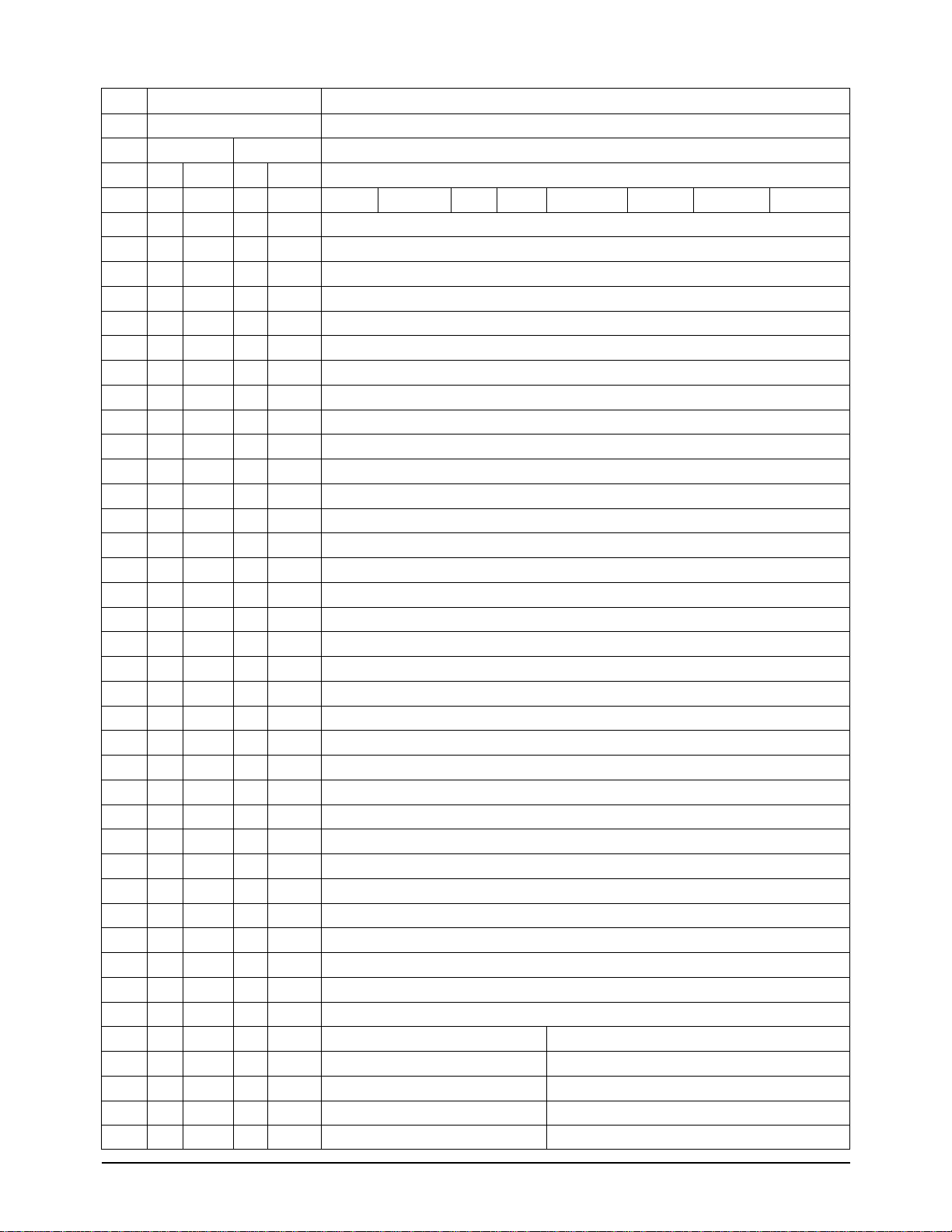
NO-OSD-DISPLAY
ADDR MODEL/DATA CONTENT (EEPROM DATA PAGE 0)
PAL NTSC
HI8 NORMAL HI8 NORMAL BIT SEGMENTATION EXPLAIN
ADDR DATA D7 D6 D5 D4 D3 D2 D1 D0
01C B4 B4 C1 C1 @WDR REGISTER[87,80] *AEW1HE[7:0]
01D 32 32 43 43 @WDR REGISTER[95,88] *AEW1HS[7:0]
01E 00 00 00 00 @WDR REGISTER[103,96] *SP_ADJ START POINT ADJUSTMENT
01F FF FF FF FF @WDR REGISTER[111,104] *TEST_ADDR[7:0]
020 00 00 00 00 @WDR REGISTER[119,112] *TEST_CNTL[7:0]
021 88 88 88 88 @WDR REGISTER[127,120] *ALPF_TH3[7:4],ALPF_TH4[3:0]
022 88 88 88 88 @WDR REGISTER[135,128] *ALPF_TH1[7:4],ALPF_TH2[3:0]
023 2A 2A 2A 2A @WDR REGISTER[143,136] *ALPF_WTSFT[7:5],ALPF_THSFT[4:3],SHPF_SFT[2:0]
024 99 99 99 99 @WDR REGISTER[151,144] *COLOR127[7:4],COLOR55[3:0]
025 99 99 99 99 @WDR REGISTER[159,152] *COLOR31[7:4],COLOR63[3:0]
026 49 49 49 49 @WDR REGISTER[167,160] *CH_SEL[7:4],COLOR12[3:0]
027 F0 F0 F0 F0 @WDR REGISTER[175,168] *BACK_SP[7:4].BACK_WT[3:0]
028 44 44 44 44 @WDR REGISTER[183,176] *LUT_TAB[7:5],LUT_HPF_SFT[4:2],X[1:0]
029 E0 E0 E0 E0 @WDR REGISTER[191,184] *LTIC[7:0]
02A C0 C0 C0 C0 @WDR REGISTER[199,192] *LIT_ON,LSI_ON,HLOG_ON,X[4:0]
02B 68 68 68 68 @WDR REGISTER[207,200] *HIST_WT HISTOGRAM WEIGHT
02C 18 18 18 18 @WDR REGISTER[215,208] *LTU-GAIN[7:0]
02D FF FF FF FF @WDR REGISTER[223,216] *LP-V[7:0] LENGTH OF VERTICAL ACTIVE AREA
02E 28 28 28 28 @WDR REGISTER[231,224] *SP-V[7:0] START OF VERTICAL ACTIVE AREA
02F B2 B2 B2 B2 @WDR REGISTER[239,232] *LP-H[7:0] LENGTH OF HORIZONTAL ACTIVE AREA
030 2E 2E 2E 2E @WDR REGISTER[247,240] *SP-H[7:0} START OF HORIZONTAL ACTIVE AREA
031 00 00 00 00 @WDR REGISTER[255,248] *GR_MODE[7:0] WDR COMMAND'00=WDR OFF, C0=WDR ON'
032 ~03F ~03F ~03F ~03F NO USED
040 10 18 18 18 * AWB- STABLE MODE THRESHOLD
041 ~048 ~048 ~048 ~048 NO USED
049 04 06 07 06 * AWB- TRACKING AREA SETTING
04A D0 D0 D0 D0 "@WDR ON ; AE A-READ(SMALL)DATA CUTTING -LOW"
04B 01 01 01 01 "@WDR ON ; AE A-READ(SMALL)DATA CUTTING -HIGH"
04C 04 04 04 04 "* AWB- R-CTRL UP/DOWN VALUE ( W/B TARGET CENTER(=80) +/- ADDR;04C )"
04D 80 80 80 80 "* AWB- B-CTRL UP/DOWN VALUE ( W/B TARGET CENTER(=80) +/- ADDR;04D )"
04E 8A 80 8A 80 * AWB- OUTDOOR HALL VALUE
04F E0 E0 E0 E0 WDR AE TARGET -LOW
050 00 00 00 00 WDR AE TARGET-HIGH
051 44 44 44 44 changed by AUTO 3MLENS ADJ(0DE) ZOOM PULSE LOW 16X LENS
052 FF FF FF FF changed by AUTO 3MLENS ADJ(0DE) ZOOM PULSE HIGH 16X LENS
053 31 33 48 2D changed by AUTO AWB ADJ(0CF) R-CONTROL 3100K
054 A0 89 C8 78 changed by AUTO AWB ADJ(0CF) B CONTROL 3100K
055 5F 60 88 5E changed by AUTO AWB ADJ(0CF) R-CONTROL 5100K
Samsung Electronics5-6
Alignment and Adjustment

NO-OSD-DISPLAY
ADDR MODEL/DATA CONTENT (EEPROM DATA PAGE 0)
PAL NTSC
HI8 NORMAL HI8 NORMAL BIT SEGMENTATION EXPLAIN
ADDR DATA D7 D6 D5 D4 D3 D2 D1 D0
056 5A 54 68 4E changed by AUTO AWB ADJ(0CF) B CONTROL 5100K
057 00 00 00 00 @DSP#12C( HAPGN) at AGC
058 00 00 00 00 @DSP#12C (HAPGN) at AGC
059 03 03 03 03 "* AWB- RATIO ; 1/3 CENTER TRACKING"
05A 03 03 03 03 "* AWB- RATIO HIGH ; CENTER AXIS OVER 5100K(OUTDOOR)"
05B 04 04 04 04 "* AWB- RATIO LOW ; CENTER AXIS BELOW 3100K(INDOOR)"
05C E0 E0 E0 E0 SHUTTER START POINT OF IRIS CONTROL PERCENT(FF=100% IRIS MAX)
05D 80 80 80 80 "@WDR ON; AE DATA CUTTING -LOW"
05E 02 02 02 02 "@WDR ON; AE DATACUTTING -HIGH"
05F 50 50 50 50 "@WDR ON; BLACK BALANCE MAX-DATA (MIN DATA+31)"
060 40 40 40 40 "@WDR ; AE-TARGET MARGIN; #087,#088 -#060, AT CLIP-COUNTER ON "
061 10 10 10 10 "@WDR ; CLIP_COUNTER-TH-'HIGH' BYTE "
062 15 15 15 15 @EIS H-TH-COUNTER
063 35 35 35 35 @EIS H-TH
064 15 15 15 15 @EIS V-TH-COUNTER
065 35 35 35 35 @EIS V-TH
066 08 08 04 04 "@WDR ON; Y ,C GAMMA 1 "
067 0D 0D 07 07 "@WDR ON; Y ,C GAMMA 2 "
068 1B 1B 15 15 "@WDR ON; Y,C GAMMA 3 "
069 32 32 2C 2C "@WDR ON; Y ,C GAMMA 4 "
06A 57 57 4D 4D "@WDR ON; Y,C GAMMA 5 "
06B 82 82 70 70 "@WDR ON; Y,C GAMMA 6"
06C C0 C0 B4 B4 "@WDR ON; Y ,C GAMMA 7"
06D F0 F0 F8 F8 "@WDR ON; Y,C GAMMA 8"
06E EE EE EE EE "@WDR ON; ADDR#12C ;YVBKT,YVBK,HBLK,YHBK"
06F 08 08 08 08 "@WDR ON; ADDR#123;YHPSC,YAPC"
070 50 50 50 50 "@WDR ON; ADDR#126;YLPFSEL"
071 10 10 10 10 "@WDR ON; ADDR#134;RED DARK SLICE"
072 03 03 03 03 "@WDR ON; ADDR#135;BLUE DARK SLICE"
073 00 00 00 00 "@WDR ON; ADDR#136;GREEN DARK SLICE"
074 11 11 10 10 @CINEMA F-ZONE LIMIT UP
075 7D 7D 68 68 @CINEMA F-ZONE LIMIT UP
076 5A 60 4B 50 @R-GAIN POSITIVE(ADDR.147) at OUTDOOR
077 55 60 3D 4A @R-GAIN NEGATIVE(ADDR.148) at OUTDOOR
078 25 2C 12 29 @R-HUE POSITIVE (ADDR.149) at OUTDOOR
079 28 3B 17 35 @R-HUE NEGATIVE (ADDR.14A) at OUTDOOR
07A 33 39 2C 31 @B-GAIN POSITIVE(ADDR.14B) at OUTDOOR
07B 2B 30 1D 21 @B-GAIN NEGATIVE(ADDR.14C) at OUTDOOR
Samsung Electronics 5-7
Alignment and Adjustment
NO-OSD-DISPLAY
ADDR MODEL/DATA CONTENT (EEPROM DATA PAGE 0)
PAL NTSC
HI8 NORMAL HI8 NORMAL BIT SEGMENTATION EXPLAIN
ADDR DATA D7 D6 D5 D4 D3 D2 D1 D0
07C 1C 1A 24 26 @B-HUE POSITIVE (ADDR.14D) at OUTDOOR
07D 0E 0E 15 0D @B-HUE NEGATIVE (ADDR.14E) at OUTDOOR
07E 50 50 50 50 @NEGA BLC TARGET-'L'
07F 00 00 00 00 @NEGA BLC TARGET-'H'
080 04 04 04 04 "@AE; AE A-WINDOW WEIGHT '05'=50%"
081 5E 5E 5E 5E "@AE; SPOTLIGHT AE-TARGET 'L'"
082 00 00 00 00 "@AE; SPOTLIGHT AE-TARGET 'H'"
083 90 90 90 90 @DIGITAL CLAMP CONTROL START AGC
084 0C 0C 0C 0C @AGC MAX , DIGITAL CLAMP CONTROL(ADDR.#118)
085 90 90 90 90 * AWB- W/B DATA-TH
086 02 02 02 02 * AWB- LUMINANCE AREA NUMBER
087 00 00 00 00 "@AE; BLC/WDR , AE TARGET 'L'"
088 02 02 02 02 "@AE; BLC /WDR, AE TARGET 'H'"
089 75 75 75 75 @SEPIA CDS-R
08A 3A 3A 3A 3A @SEPIA CDS-G
08B 00 00 00 00 "@AE; SAND&SNOW MODE AE TARGET 'L'"
08C 02 02 02 02 "@AE; SAND&SNOW MODE AE TARGET 'H'"
08D 00 00 00 00 changed by AUTO 3MLENS ADJ(0DE) @FOCUS TELE MARGIN LOW BYTE(CANON X22 LENS)
08E 00 00 00 00 changed by AUTO 3MLENS ADJ(0DE) @FOCUS TELE MARGIN HIGH BYTE(CANON X22 LENS)
08F F0 F0 F0 F0 changed by AUTO 3MLENS ADJ(0DE) @FOCUS WIDE MARGIN LOW BYTE(CANON X22 LENS)
090 FF FF FF FF changed by AUTO 3MLENS ADJ(0DE) @FOCUS WIDE MARGIN HIGH BYTE(CANON X22 LENS)
091 F8 09 00 0A @CCD H-PIXEL NUMBER -LOW BYTE
092 02 02 03 02 @CCD H-PIXEL NUMBER -HIGH BYTE
093 23 23 F7 F7 @CCD V LINE NUMBER -LOW BYTE
094 01 01 00 00 @CCD V LINE NUMBER -HIGH BYTE
095 1C 0C 16 09 @CCD V SKIP LINE DEFAULT VALUE
096 B9 46 50 EE @CCD V LINE NUMBER LOW BYTE
097 02 02 02 01 @CCD V LINE NUMBER HIGH BYTE
098 98 98 98 98 "@DSP IC ADDR #41H ;ART DSE LEVEL"
099 B8 B8 B8 B8 "@DSP IC ADDR #1CH ;NEGA MODE WHITE CLIP LEVEL"
09A 30 30 30 30 * AWB- START HALL VALUE
09B 1C 1C 1C 1C "@DSE- MOSAIC SIZE; DSP IC ADDR #39H "
09C F4 F4 F4 F4 "@D/ZOOM MAX RATIO; CO=4X, EE=14.3X, F4= 20X "
09D 68 68 68 68 @ NOISE SLICE START AGC VALUE
09E 0B 0B 0B 0B @ HAP(DSP #10BH) MIN VALUE AT AGC MAX
09F 0B 0B 0B 0B @ VAP(DSP 310C) MIN VALUE AT AGC MAX
0A0 18 20 18 20 @ YAP(DSP #10DH) MAX VALUE AT AGC MAX
0A1 A0 A0 A0 A4 @ CHROMA SUPPRESS PERCENT
Samsung Electronics5-8
Alignment and Adjustment
NO-OSD-DISPLAY
ADDR MODEL/DATA CONTENT (EEPROM DATA PAGE 0)
PAL NTSC
HI8 NORMAL HI8 NORMAL BIT SEGMENTATION EXPLAIN
ADDR DATA D7 D6 D5 D4 D3 D2 D1 D0
0A2 60 60 60 60 @ CHROMA SUPPRESS START AGC VALUE
0A3 00 00 00 00 changed by AUTO IRIS ADJ(0CE) @ IRIS CONTROL MAX LOW BYTE
0A4 05 05 05 05 changed by AUTO IRIS ADJ(0CE) @ IRIS CONTROL MAX HIGH BYTE
0A5 B4 B4 B4 B4 * AWB -AT OUTDOOR,TRACKING AMOUNT(IN CASE,INDOOR DATAINPUT) ,B4=70%,FF=0%(NO TRACKING)
0A6 C0 C0 C0 C0 * AWB- WB AGC% , STOP POINT ( 80=50%, C0=75%)
0A7 89 89 89 89 @HALL WIDTH AT HALL ADJUST
0A8 E5 E5 E5 E5 changed by AUTO 3MLENS ADJ(0DE) @ZOOM RESET LOW(16X, 22X LENS)
0A9 88 88 88 88 changed by AUTO 3MLENS ADJ(0DE) @ZOOM RESET HIGH(16X, 22X LENS)
0AA 80 80 80 80 changed by ZOOM VR CENTER(0D6) @ZOOM VR CENTER VALUE
0AB 20 20 20 20 @ZOOM VR CENTER MARGIN( ZOOM STOP PERIOD)
0AC 34 30 34 30 changed by AUTO AGC ADJ(0DB) @AGC MIN VALUE
0AD A8 A8 A8 A8 changed by AUTO AGC ADJ(0DB) @AGC MAX VALUE
0AE 0B 0B 09 09 "REMOCON ZOOM SPEED; 22X LENS -PAL:0B NTSC:09 "
0AF 02 02 02 02 AF ZIGZAG AMOUNT AT BASIC ZOOM SPEED
0B0 68 28 5B 30 @IN AGC AUTO ADJUST (ADDR.0DB), SHUTTER CONTROL OF AGC MIN ADJUST OPERATING(D0='0'FIX)
0B1 2A 2B 08 01 @IN AGC AUTO ADJUST (ADDR.0DB), SHUTTER CONTROL OF AGC MAX ADJUST OPERATING(D7='1'FIX)
0B2 ~0B6 ~0B6 ~0B6 ~0B6 NO USED
0B7 1A 1A 16 16 "ZOOM MAX SPEED ;22X LENS PAL:19H,NTSC:15H"
0B8 3A 3A 3A 3A @HALL REF START, AT AUTO HALL ADJUST ADDR.0CD
0B9 4C 4C 4C 4C @HALL GAIN START, AT AUTO HALL ADJUST ADDR.0CD
0BA 40 40 40 40 changed by AUTO HALL ADJ(0CD) @HALL MIN VALUE
0BB C0 C0 C0 C0 changed by AUTO HALL ADJ(0CD) @HALL MAX VALUE
0BC E0 D0 D0 D0 @AE TARGET-LOW BYTE
0BD 00 00 00 00 @AE TARGET-HIGH BYTE
0BE B0 B0 B0 B0 changed by AUTO IRIS ADJ(0CE) @IRIS CONTROL MIN LOW BYTE
0BF 09 09 09 09 changed by AUTO IRIS ADJ(0CE) @IRIS CONTROL MIN HIGH BYTE
0C0 18 18 18 18 changed by AUTO 3MLENS ADJ(0DE) @FOCUS RESET LOW(16X,22X LENS)
0C1 82 82 82 82 changed by AUTO 3MLENS ADJ(0DE) @FOCUS RESET HIGH(16X,22X LENS)
0C2 40 40 40 40 @HALL CLOSE TARGET
0C3 ~C6 ~C6 ~C6 ~C6 NO USED
0C7 12 12 12 12 EIS GYRO-RESET TIME '0C=3.7SEC'
0C8 13 13 13 13 EIS START TIME ('10'=4.4SEC) AFTER EIS GYRO-RESET
0C9 65 64 65 60 @IRIS CONTROL OF ZOOM WIDE POSITION AT LENS ADJUSTMENT
0CA 24 24 24 24 @QB_GCTRL
0CB 48 48 48 48 @AETAR L (FLEX-ZONE)
0CC 00 00 00 00 @AETAR H (FLEX-ZONE)
0CD FF FF FF FF @@HALL AUTO ADJUST
0CE FF FF FF FF @@IRIS AUTO ADJUST
Samsung Electronics 5-9
Alignment and Adjustment
 Loading...