


SCC-B1311
DIGITAL COLOR CAMERA
operating instructions
imagine the possibilities
Thank you for purchasing this Samsung product.
To receive more complete service, please register your product at
www.samsung.com/global/register
safety precautions
CAUTION
RISK OF ELECTRIC SHOCK. DO NOT OPEN
CAUTION: TO REDUCE THE RISK OF ELECTRIC SHOCK,
DO NOT REMOVE COVER (OR BACK)NO USER-SERVICEABLE PARTS
INSIDE REFER SERVICING TO QUALIFIED SERVICE PERSONNEL
This symbol indicates that dangerous voltage constituting a risk of electric shock is present within
this unit.
This symbol indicates that there are important operating and maintenance instructions in the
literature accompanying this unit.
WARNING
•
To reduce the risk of fire or electric shock, do not expose this appliance to rain or moisture.
•
To prevent injury, this apparatus must be securely attached to the floor/wall in accordance with the
installation instructions.
•
If this power supply is used at 240V AC, a suitable plug adapter should be used.
WARNING
1. Be sure to use only the standard adapter that is specified in the specification sheet.
Using any other adapter could cause fire, electrical shock, or damage to the product.
2. Incorrectly connecting the power supply or replacing battery may cause explosion, fire,
electric shock, or damage to the product.
3. Do not connect multiple cameras to a single adapter. Exceeding the capacity may cause
abnormal heat generation or fire.

4. Securely plug the power cord into the power receptacle. Insecure connection may cause fire.
5.
When installing the camera, fasten it securely and firmly. The fall of camera may cause personal injury.
6. Do not place conductive objects (e.g. screwdrivers, coins, metal parts, etc.) or containers filled
with water on top of the camera. Doing so may cause personal injury due to fire, electric shock,
or falling objects.
7.
Do not install the unit in humid, dusty, or sooty locations. Doing so may cause fire or electric shock.
8. If any unusual smells or smoke come from the unit, stop using the product.
In such case, immediately disconnect the power source and contact the service center.
Continued use in such a condition may cause fire or electric shock.
9. If this product fails to operate normally, contact the nearest service center.
Never disassemble or modify this product in any way. (SAMSUNG is not liable for problems
caused by unauthorized modifications or attempted repair.)
10. When cleaning, do not spray water directly onto parts of the product.
Doing so may cause fire or electric shock.
CAUTION
1. Do not drop objects on the product or apply strong blows to it.
Keep away from a location subject to excessive vibration or magnetic interference.
2. Do not install in a location subject to high temperature (over 122°F), low temperature (below
14°F), or high humidity. Doing so may cause fire or electric shock.
3. If you want to relocate the already installed product, be sure to turn off the power and then
move or reinstall it.
4. Remove the power plug from the outlet when there is a lighting storm.
Neglecting to do so may cause fire or damage to the product.
5. Keep out of direct sunlight and heat radiation sources. It may cause fire.
6. Install it in a place with good ventilation.
7. Avoid aiming the camera directly towards extremely bright objects such as sun, as this may
damage the CCD image sensor.
8. Apparatus shall not be exposed to dripping or splashing and no objects filled with liquids,
such as vases, shall be placed on the apparatus.
9. The Mains plug is used as a disconnect device and shall stay readily operable at any time.
ENG

FCC STATEMENT
This device complies with part 15 of the FCC Rules. Operation is subject to the following two
conditions:
1) This device may not cause harmful interference, and
2) This device must accept any interference received including interference that may cause
undesired operation.
This equipment has been tested and found to comply with the limits for a Class A digital device, pursuant to part
15 of FCC Rules. These limits are designed to provide reasonable protection against harmful interference when the
equipment is operated in a commercial environment.
This equipment generates, uses, and can radiate radio frequency energy and, if not installed and used in accordance
with the instruction manual, may cause harmful interference to radio communications. Operation of this equipment
in a residential area is likely to cause harmful interference in which case the user will be required to correct the
interference at his own expense.
IC Compliance Notice
This Class A digital apparatus meets all requirements of the Canadian Interference.-Causing Equipment Regulations
of ICES-003.
important safety instructions
1. Read these instructions.
2. Keep these instructions.
3. Heed all warnings.
4. Follow all instructions.
5. Do not use this apparatus near water.
6. Clean only with dry cloth.
7.
Do not block any ventilation openings. Install in accordance with the manufacturer’s instructions.
8. Do not install near any heat sources such as radiators, heat registers, or other apparatus
(including amplifiers) that produce heat.
9. Do not defeat the safety purpose of the polarized or grounding-type plug.
A polarized plug has two blades with one wider than the other.
A grounding type plug has two blades and a third grounding prong.
The wide blade or the third prong is provided for your safety.
If the provided plug does not fit into your outlet, consult an electrician for replacement of the
obsolete outlet.
10. Protect the power cord from being walked on or pinched particularly at plugs, convenience
receptacles, and the point where they exit from the apparatus.
11. Only use attachments/accessories specified by the manufacturer.
12. Use only with cart, stand, tripod, bracket, or table specified by the manufacturer,
or sold with the apparatus.
13. Unplug this apparatus when a card is used. Use caution when moving the cart/
apparatus combination to avoid injury from tip-over.
14. Refer all servicing to qualified service personnel.
Servicing is required when the apparatus has been damaged in any way, such as powersupply cord or plug is damaged, liquid has been spilled or objects have fallen into the
apparatus, the apparatus has been exposed to rain or moisture, does not operate normally,
or has been dropped.
Apparatus shall not be exposed to dripping or splashing and no objects filled with liquids, such as vases, shall be
placed on the apparatus
ENG
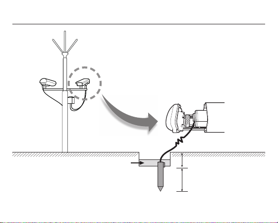
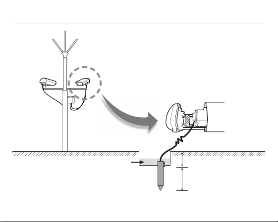
external cctv camera installation
1
Installing the lightening conductor and grounding system.
Separate grounding system.
2
Installing the camera and grounding system.
Grounding wire to a good earth ground (100Ω or less ground
resistance.) (Class 3)
3
Class 3 camera grounding
Separate grounding system from the lightening conductor.
➧
The surface
Treating the raw materials that reduce the
ground resistance around the ground rods.
Ground resistance:
100Ω or less.
< Construction of the ground rod >
Diameter :
300Φ
Higher than 0.75 meter
The height of the ground rod:
Higher than 3 meters.
(One meter by minimum)
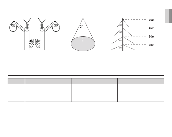
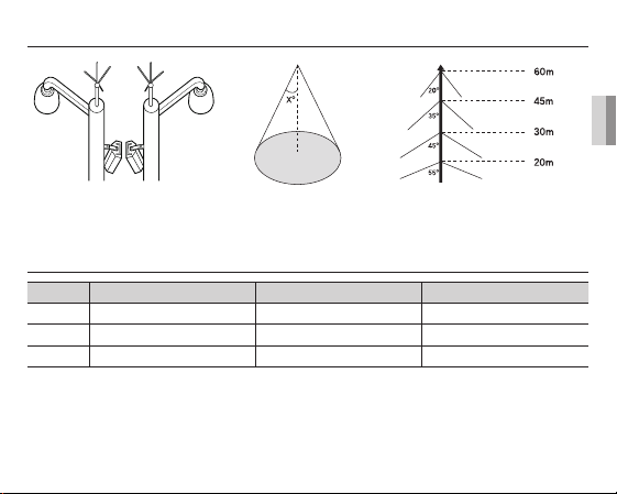
1. Installing a lightening conductor
ENG
a) Protection area b) Protected angle
(Depending on the height of the
lightning conductor)
2. Camera grounding
No Distinguished by Standard Note
1
2
3
The purpose of the camera grounding
Installing the lightning conductor and grounding the camera chassis prevent the CCTV camera from lightning strikes.
When installing the CCTV camera outside, avoid the damages from the lightning strikes by using the lightning conductor
and camera grounding.
Grounding method Class 3 CCTV product
Thickness of the Grounding wire 1.6mm2
Ground resistance
100Ω
6

contents
OVERVIEW
02 Overview
02
FEATURES
03 Features
03
INSTALLATION
04
SPECIFICATIONS
01
11
04 Package
04 Parts & Description
05 Things to keep in mind during Installation
and Use
05 Connect the auto iris lens connector
06 Install the lens
06 Adjust the back focus
07 Connect the cables and check the operation
11 Specifications

overview
It is a high-resolution box camera that has implemented the horizontal resolution of 540 lines by taking advantage of the
Digital Signal Processing and OLPF technologies.
In mechanical fluorescent lighting conditions, you can experience so-called “color rolling” if you have
•
installed the manual iris lens on the camera and positioned the function switch from ELC to ON. In this
case, connect the camera to the power source (AC) and position the L/L switch on the rear panel to EXT.
(NTSC: 60Hz, PAL: 50Hz)
- What is Color Rolling?
This occurs because the mechanical fluorescent lighting blinks from power frequencies, where the
color temperature input to the camera is not certain so the color on the screen changes irregularly
(red, blue, yellow, etc).
- This problem can be solved by using the Line Lock function or the Auto Iris Lens.
ENG
02

features
High Color Sensitivity
Resolution
Excellent Back Light
Compensation
Digital Power Synchronization
Dynamic CCD Defect
Compensation
03
The camera adopts the latest 1/3” Super-HAD IT CCD to get the benefit
of high color sensitivity.
Introduces Full Digital Image Processing from the digital signal technology
to implement a high-resolution image.
This will guarantee a sharp image by compensating for the back light
even if the sunlight or bright lighting reflects against the subject.
Adopts the full digital line lock system to enable you to adjust the vertical
synchronization of the camera, an enhancement of manipulation and
reliability.
Uses advanced technology to compensate CCD defects in any mode, to give
clear, sharp and noise-free images, even in low contrast scenes.
installation
In this chapter, we will provide you with general
instructions for product installation and preferred places
as well as considerations before installation. Now, let’s
install the camera and connect necessary cables.)
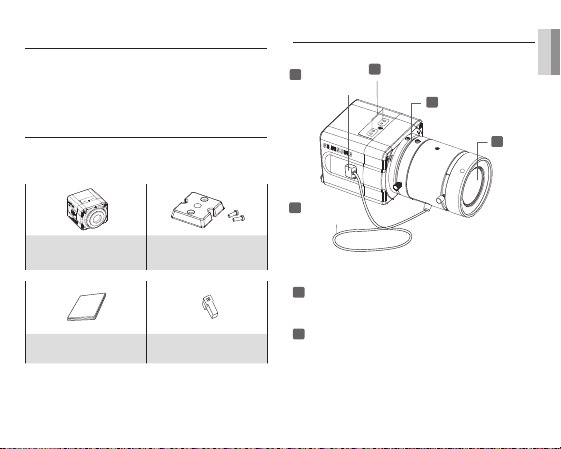
Package
You must check that all the components and accessories
listed below are included in the product package.
Camera
User’s guide Auto Iris Lens Connector
Camera Holder
(Mount Adaptor) screw x2
Parts & Description
1
3
Auto Iris Lens
Connector
5
Auto Iris Lens
Control Cable
1
Mount Adaptor Holes
Used to fix the mount adaptor with a screw if you
want to mount the camera on the bracket.
2
Auto Iris Lens (Optional)
A lens to be installed on the camera
- If the camera gets dirty on the surface of the lens,
apply ethanol to the provided tissue or a dry cloth
and wipe it out.
Mount Adaptor Holes
4
Flange Back
Adjustable Ring
2
Auto Iris
Lens
ENG
04
3
Auto Iris Lens Connector
Provides power source and control/ DC signal with
iris lens that are required to control the iris of the lens
4
Flange Back Adjustable Ring
Used to adjust the back focus of the camera.
5
Auto Iris Lens Control Cable
Transfers the control signal from the camera to the
iris lens.
Things to keep in mind during
installation and Use
Do not disassemble the camera on your own.
•
Always be careful when handling the camera.
•
Do not strike the camera by your fists or shake
it. Please be careful not to be careless when
storing and operating it.
Do not place or operate the camera in any wet
•
environment such as rain or wet surfaces.
Do not clean the camera with rough sandpaper.
•
Please always use a dry cloth when cleaning it.
Put the camera in a cool area free from direct
•
sunlight. Otherwise, the camera may be damaged.
05
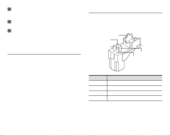
Connect the auto iris lens connector
Remove the sheath round the iris control cable and
connect it to each of the auto iris lens connector as
described below.
Rib
Pin3
Pin1
Pin4
Pin2
Pin Number DC Control Type
1 Damp(–)
2 Damp(+)
3 Drive(+)
4 Drive(–)
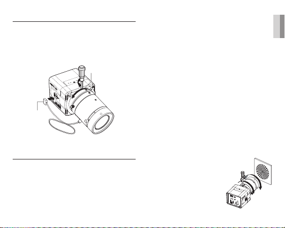
Install the lens
Loosen the single screw on the adjustable ring of the
flange back by turning it anti-clockwise and turn the
ring in the “C” direction (anti-clockwise) to the end.
Otherwise, it can cause damage to the internal image
sensor or the lens when you install the lens on the
camera.
Iris Control
Cable
C direction
Adjust the back focus
The back focus of a camera is predefined by the
factory default. However, some models are out of focus
depending on the lens type. If your camera is out of
focus, follow the instructions below to adjust the back
focus. The following is the procedure used to set the
proper back focus point in fixed focus lenses.
Lens without zooming feature
1.
Capture a sharp subject (with a grid pattern) more than
10m apart and adjust the focus ring to the infinity (∞).
2. Adjust the adjustable ring of the flange back so that
you can capture the sharpest image.
3. Fasten the screw of the adjustable ring of the flange
back.
Lens with zooming feature
1. Capture a sharp subject (with a grid pattern) 3-5m
apart and adjust the zoom in the TELE (zooming)
direction as possible and also adjust the focus ring so
that you can capture the sharpest image.
2. Adjust the zoom in the WIDE direction as possible and
turn the adjustable ring of the flange back so that you
can capture the sharpest image.
3. Repeat 1 and 2 above 2-3 times to match the focus
from the ZOOM TELE side with that from the ZOOM
WIDE side.
4. Fasten the screw of the adjustable ring of the flange
back.
- If you darken the image before
adjusting the focus by attaching
the ND filter to the front of the lens,
you can get a sharper focus.
ENG
06
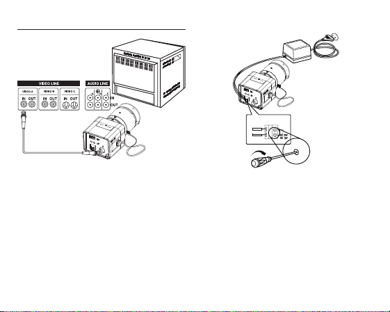
Connect the cables and check the operation
VIDEO IN Terminal on
the rear of moniter
BNC Cable
VIDEO OUT Terminal
1. Connect one end of the BNC cable to the VIDEO OUT
port of the monitor.
2. Connect the other end of the BNC cable to the VIDEO
In port.
3. Connect the camera to the power adaptor. Use a
slotted flat (-) screwdriver to connect one end of the
two-line power adaptor to the DC/AC IN port of the
camera. (GND: marked with a white line on the cable)
- You can plug in to a power outlet regardless of the
polarity for both AC 24V and DC 12V adaptor.
07
AC24V/DC12V models (SCC-B1311, B1311P)
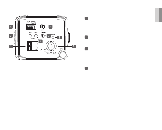
1
Power Port
Port that is connected to the power (adaptor) cable.
- For SCC-B1311, B1311P
Connects to AC 24V or DC 12V.
2
Power Indication LED
If properly supplied with power, the LED turns on.
3
Vertical Synchronization Phasing Switch (Left)
Used to adjust the vertical synchronization phasing.
If pressed, the vertical synchronization moves to the
left.
4
Vertical Synchronization Phasing Switch
(Right)
Used to adjust the vertical synchronization phasing.
If pressed, the vertical synchronization moves to the
right.
ENG
08

5
FUNCTION SWITCH-1
1. ELC
2. BLC
3. FL(Flickerless)
4. AWB
SW1(ELC)
Use this for the manual iris lens. If set to ON, the electronic
shutter speed varies between 1/60 and 1/120,000 second
to keep the screen brightness proper. However, you must
position this switch to OFF if you are using the auto iris
lens (DC control type). Because, in this mode, the camera
can show the color rolling effect when operating under the
mechanical fluorescent lightning. If this happens, apply the
AC power and set the L/L to "EXT". (NTSC: 60Hz, PAL:
50Hz)
SW2(BLC)
Use to compensate for a display that is too bright or too
dark when indoor lighting or windows reflects against the
subject. Set to ON for these conditions.
09
SW3(FL)
It is an anti-flicker system that prevents the flickering of the
image due to mismatch between the vertical sync frequency
and the on-off frequency of lighting.
It is used when the camera and broadcasting system within
its own region do not match each other. If set to ON, the
electronic shutter speed stays at either 1/100sec (NTSC) or
1/120sec (PAL).
If SW1 (ELC) is set to ON, the anti-flicker system
does not work even if SW3 is positioned to ON.
SW4(AWB)
ON(ATW): It automatically adjusts the image color
according to the temperature change of the
lightning color. Under a very irregular lightning
condition (such as car headlight), if set to ON,
it captures a subject normally (white).
OFF(AWC): It remembers the normal color temp switch
with the OFF to operate at a certain white
balance level.
Note that AWB can cause an error in the following
conditions:
- If a big subject of a uniform color with a high
saturation exists in the center of the screen or
if few part of the image is in white.
- If lighting is made of special material like
sodium.
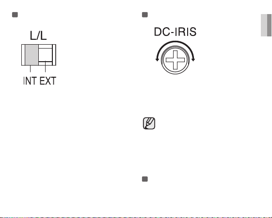
6
FUNCTION SWITCH-2
If multiple cameras are connected to a sequential
switcher in auto switch mode, the camera in the internal
sync mode causes skip every time it moves to another
scene. However, this can be solved by positioning the
L/L switch to EXT and using the level bar to adjust the
vertical sync phasing.
- INT: It operates in the internal synchronization mode.
- EXT: it operates in the power synchronization mode.
※
If your camera uses DC 12V for power source,
it operates in the internal mode regardless of the
position (EXT/INT) of the L/L switch.
7
DC IRIS Level Bar
Used to adjust the iris level of this level bar using a
screwdriver.
- Anti-clockwise: Decreases the luminance level.
- Clockwise: Increases the luminance level.
- The IRIS range of the DC lens is about between
80IRE and120IRE. In other words, the DC lens
adopts a variable range limitation system, rather
than IRIS Full Open/Close system.
- Depending on the type of the lens used that
allows setting the value below 75 IRE may cause
IRIS hunting. Therefore, make sure that the
range is set to an appropriate level (higher than
80 IRE).
8
Video Out Port
Connected to the Video Out port of a monitor.
The video signal is output via this port.
ENG
10

specifications
SCC-B1311
Item Description
Product Type Surveillance Camera
Broadcasting
System
Imaging Device 1/3”IT, S-HAD-CCD
Number of Effective
Pixels
Scanning 525 Lines, 2:1 interlace
Line Frequency
Synchronous Mode
Horizontal
Resolution
S/N Ratio Approx. 50dB
Minimum Subject
Illumination
ALC/ELC
11
NTSC STANDARD SYSTEM
768(H) x 494(V)
INTERNAL : 15,734Hz(H)
59.94 Hz(V)
LINELOCK : 15,750Hz(H)
60 Hz(V)
INTERNAL
LINE LOCK (AC 24V)
540TV Lines
0.40Lux (F1.2, 50IRE)
0.24Lux (F1.2, 30IRE)
0.12Lux (F1.2, 15IRE)
ALC: DC IRIS LENS Only
ELC: Electronic Shutter Iris
(max. 1/120Ksec)
Item Description
FL(FLICKERLESS) OFF/ON
Lens Manual/Auto Iris DC Lens
Lens Mount C, CS Lens Adaptable
AWB (Auto White
Balance)
BLC (Back Light
Compensation)
AGC AUTO
Signal Out
Power
Power Consumption Approx. 3.0 Watts
Operation
Temperature
Operation Humidity ~90%
Dimensions (mm) 68(W) x 55(H) x 77.1(D)
Weight 220 g
ON : ATW
OFF : AWC
ON/OFF
COMPOSITE VIDEO OUT
1V p_p 75Ω / BNC
AC24V ±10%(60Hz±0.3Hz),
DC12V+10%~-5%
-10°C ~ +50°C

SCC-B1311P
Item Description
Product Type Surveillance Camera
Broadcasting
System
Imaging Device 1/3”IT, S-HAD-CCD
Number of
Effective Pixels
Scanning 625 Line, 2:1 interlace
Line Frequency
Synchronous
Mode
Horizontal
Resolution
S/N Ratio Approx. 50dB
Minimum
Subject
Illumination
ALC/ELC
PAL STANDARD SYSTEM
752(H) x 582(V)
15,625Hz(H) 50 Hz(V)
INTERNAL :
LINE LOCK :
15,625Hz(H) 50 Hz(V)
INTERNAL
LINE LOCK (AC 24V)
540 TV Lines
0.40Lux (F1.2, 50IRE)
0.24Lux (F1.2, 30IRE)
0.12Lux (F1.2, 15IRE)
ALC : DC IRIS LENS Only
ELC : Electronic Shutter Iris
(max. 1/120Ksec)
ENG
Item Description
FL(FLICKERLESS)
Lens Manual/Auto Iris DC Lens
Lens Mount C, CS Lens Adaptable
AWB(Auto White
Balance)
BLC(Back Light
Compensation)
AGC Auto
Signal Out
Power
Power
Consumption
Operation
Temperature
Operation
Humidity
Dimensions (mm)
Weight 220 g
OFF/ON
ON : ATW
OFF : AWC
ON/OFF
COMPOSITE VIDEO OUT
1V p_p 75Ω / BNC
AC24V ±10%(50Hz±0.3Hz),
DC12V+10%~-5%
approx. 3.0 Watts
-10°C ~ +50°C
~90%
68(W) x 55(H) x 77.1(D)
12

Memo

SCC-B1311
CAMERA COULEUR NUMÉRIQUE
Mode d'emploi
FRA
imaginez toutes les possibilités
Pour obtenir notre service complet, veuillez enregistrer le produit sur le
Merci d’avoir acheté ce produit Samsung.
portail desélectionnez Enregistrement de produit
http://www.samsung.com/cp/et
mesures de sécurité
ATTENTION
RISQUE DE ECHOC ELECTRIQUE
ATTENTION : POUR REDUIRE LES RISQUES DE CHOCS ELECTRIQUES,
NE RETIREZ PAS LE COUVERCLE (OU LA PARTIE ARRIERE) LES PIECES
INTERIEURES NE SONT PAS ACCESSIBLES A L’UTILISATEUR. FAITES APPEL AU
Ce symbole indique la présence, dans cette unité, d’une tension élevée et avise des risques de décharge électrique
existants.
Ce symbole indique la présence, dans cette unité, d’une tension élevée et avise des risques de décharge électrique
existants.
PERSONNEL DE MAINTENANCE QUALIFIE.
AVERTISSEMENT
Afin de réduire le risque d’incendie ou de décharge électrique, n’exposez pas cet appareil à la pluie ni
•
à l’humidité.
Afin d’éviter les blessures personnelles, fixez fermement l’appareil au sol/à la paroi conformément aux
•
instructions d’installation.
Si vous utilisez une alimentation électrique à 240V ca, utilisez un adaptateur de fiche approprié.
•
AVERTISSEMENT
1. Utiliser uniquement l’adaptateur standard spécifié dans la fiche technique. L’utilisation de tout autre adaptateur
peu causer un incendie, un choc électrique ou endommager le produit.
2. La connexion incorrecte de la source d’alimentation ou le remplacement incorrect de la batterie peut provoquer
une explosion, un incendie, un choc électrique ou endommager le produit.
3. Ne pas brancher plus d’une caméra à un adaptateur. Dépasser la capacité peut générer une chaleur anormale
ou un incendie.
NE PAS OUVRIR

4. Brancher le cordon d’alimentation sécuritairement à la prise secteur. Une mauvaise connexion peu provoquer un
incendie.
5. Lors de l’installation de la caméra, la fixer solidement et sécuritairement. La chute d’une caméra peut causer des
blessures corporelles.
6. Ne pas placer d’objets conducteurs (comme des tournevis, pièces de monnaie, objets métalliques, etc.) ou de
contenant remplis d’eau sur la caméra. Cela peut causer des blessures corporelles provoquer par un incendie, un
choc électrique ou la chute d’objets
7. Ne pas installer l’appareil dans un endroit humide, poussiéreux ou plein de suie. Cela peut causer un incendie ou un
choc électrique.
8. Si des odeurs ou des fumées inhabituelles s’échappent de l’appareil, arrêter d’utiliser l’appareil. Dans un tel cas,
débrancher immédiatement le cordon d’alimentation et contacter le centre de service. Un usage continu dans de
telles conditions peut causer un incendie ou un choc électrique.
9. Si l’appareil ne fonctionne pas normalement, contacter le centre de service le plus proche. Ne jamais démonter ou
modifier de quelle que façon que ce soit ce produit. (SAMSUNG n’est pas responsable des anomalies provoquées
par des modifications ou tentatives de réparation non autorisées.)
10. Lors du nettoyage, ne pas vaporiser d’eau directement sur les composants du produit. Cela peut causer un incendie
ou un choc électrique.
AVERTISSEMENT
1.
Ne pas laissez tomber d’objet sur le produit ou le soumettre à de violents chocs. Ne pas placer le produit dans un
endroit où il pourrait subir de forte vibration ou des interférences magnétiques.
2. Ne pas installer le produit a des emplacements soumis aux temperatures elevees (superieures a 122 °F), aux
temperatures faibles (inferieures a 14°F), ou a une humidite elevee. Cela peut provoquer des risques d’incendie
ou des chocs electriques.
3. Si vous désirez déplacer le produit déjà installé, coupez l’alimentation puis déplacez ou réinstallez le produit.
4. En cas d’orage, retirer la fiche de la prise électrique. Le non-respect de cette consigne peut provoquer un incendie
ou endommager le produit.
5. Placer le produit dans un endroit protégé des rayons du soleil et des sources de chaleur. Cela peut provoquer un
incendie.
6. Installer dans un endroit bien ventilé.
7. Éviter de diriger la caméra en direction d’objets extrêmement brillants, tel que le soleil, pour ne pas endommager le
capteur d’image CCD.
8.
Veillez à éviter toute projection sur l’appareil et ne placez jamais de récipients contenant un liquide (ex. : vase) dessus.
9. La prise d’alimentation fait office de système de déconnexion ; elle doit donc rester disponible en permanence.
FRA

Déclaration relative à la Commission fédérale des communications (FCC)
Ce produit satisfait à la réglementation de la FCC lorsque des câbles et des connecteurs blindés
sont utilisés pour raccorder cet appareil à un autre équipement.
Pour éviter toute interférence électromagnétique avec des appareils électriques, comme des
postes de radio et de télévision, utiliser des câbles et des connecteurs blindés.
Cet appareil a été testé et trouvé conforme aux limites d’un appareil numérique de classe A, en vertu de la partie 15
des règlements de la FCC. Ces limites sont conçues pour fournir une protection raisonnable contre les interférences
nuisibles dans une installation résidentielle. Cet appareil génère, utilise et peut rayonner une énergie radiofréquence
et, s’il n’est pas
installé ou utilisé conformément aux directives, il peut provoquer des interférences nuisibles aux
radiocommunications. Cependant, il n’y a aucune garantie qu’aucune interférence ne se produira dans une
installation particulière.
Si cet appareil provoque des interférences nuisibles à la réception de signaux de radio ou de télévision, ce qui
peut se confirmer en allumant et éteignant l’appareil, il est conseillé à l’utilisateur d’essayer de remédier à ces
interférences au moyen d’une ou plusieurs mesures suivantes :
• Réorienter ou déplacer l’antenne de réception.
• Augmenter la distance de séparation entre l’appareil et le récepteur.
• Brancher l’appareil à une prise sur un circuit différent de celui auquel le récepteur est branché.
• Consulter le détaillant ou un technicien radio/TV d’expérience pour obtenir de l’aide.
IC Compliance Notice
Cet appareil numérique de classe A respecte toutes les exigences du Réglement ICES-003 sur les équipements
produisant des interférences au Canada.
instructions importantes relatives à la sécurité
1. Veuillez lire ces instructions.
2. Conservez ces instructions.
3. Prêtez attention à tous les avertissements.
4. Veuillez suivre toutes les instructions.
5. N’utilisez pas cet appareil à proximité de l’eau.
6. Nettoyez-le avec un tissu sec.
7. N’obstruez pas les ouvertures de ventilation. Procédez à l’installation conformément aux
instructions du fabricant.
8. Ne pas installer l’appareil à proximité de sources de chaleur comme les radiateurs, les registres de
chaleur et les autres appareils (incluant les amplificateurs) produisant de la chaleur.
9. Veillez à vous conformer aux sécurités des prises de terre et polarisées. Une prise dite polarisée
est composée de deux fiches, une plus large que l’autre. Une prise de terre est composée de deux
fiches et d’une troisième fiche pour la terre. La troisième fiche, plus large que les deux autres, est
fournie pour votre sécurité. Si la prise qui vous est fournie ne correspond pas à votre prise murale,
demandez à un électricien de remplacer la prise obsolète.
10. Veillez à ce que personne ne marche ou se prenne les pieds dans le cordon d’alimentation et
particulièrement au niveau des fiches et des prises de courant et au niveau où ils se situent.
11. N’utilisez que des accessoires ou des produits additionnels spécifiés par le fabricant.
12. N’utilisez que des chariots, des pieds, trépieds, ou tables spécifiés par le fabricant ou
vendus avec l’appareil.
13. Débranchez cet appareil. Si vous utilisez un chariot, faîtes attention lorsque que vous
déplacez l’appareil et le chariot pour éviter les blessures causées par un renversement.
14. Veuillez faire appel au personnel qualifié pour tous travaux de maintenance. Les travaux de
maintenance sont nécessaires si l’appareil a été endommagé de quelque manière que ce soit,
comme cordon d’alimentation endommagé, liquide répandu, objets tombés sur l’appareil, appareil
exposé à la pluie et à l’humidité, il ne fonctionne pas normalement ou est tombé par terre.
L’appareil ne doit pas être exposé à la pluie ou aux éclaboussures, et aucun objet rempli de liquide, comme un
vase, ne doit être posé sur lui.
FRA
installation de caméra de surveillance externe
1
Installer le paratonnerre et le système de mise à la terre.
Système de mise à la terre séparé.
2
Installer la caméra et le système de mise à la terre.Câble de
mise à la terre pour une bonne mise à la terre (100Ω ou moins
de résistance de terre.) (Classe 3)
3
Classe 3. (Mise à la terre de la caméra) Système de mise à la
terre séparé du paratonnerre.
➧
La surface
Traiter les matières premières qui réduisent
la résistance de terre autour des barres de
mise à la terre.
Résistance de terre :100Ω ou moins.
< Structure de la barre de mise à la terre >
Diamètre :
300Φ
Supérieure à 0,75 mètres
Hauteur de la barre de mise à
la terre : Supérieure à 3 mètres
(Un mètre au maximum.)
1. Installer un paratonnerre
FRA
a) Zone de protection
b) Angle protégé
(En fonction de la hauteur du para-
tonnerre)
2. Mise à la terre de la caméra
No Distingué par Standard Remarque
Méthode de mise à la terre Classe 3
1
Épaisseur du câble de mise à la terre
2
3
Objectif de la mise à la terre de la caméra
Installer le paratonnerre et relier à la terre le châssis de la caméra évitent à la caméra de surveillance d'être frappée par
la foudre. Lorsque vous installez la caméra de surveillance à l'extérieur, évitez les dommages causés par la foudre en
utilisant le paratonnerre et la mise à la terre de la caméra.
Résistance de terre
1,6 mm2
100Ω
Produit de télévision en circuit fermé
7

contenu
VUE GÉNÉRALE
02
CARACTÉRISTIQUES
03
INSTALLATION
04
FICHE TECHNIQUE
02 Vue générale
03
Caractéristiques
04 Emballage
04 Pièces et description
05 Choses à garder à l’esprit pendant
l’installation et l’utilisation
05 Branchez la fiche de connexion de l’objectif à
diaphragme automatique
06 Installez l’objectif
06 Ajustez la mise au point arrière
07 Branchez les câbles et vérifiez l’utilisation
11 Fiche technique
01
11

vue générale
Il s'agit d'une caméra haute résolution avec boîtier utilisant la résolution horizontale de 540 lignes en bénéficiant du
processus de signal numérique et des technologies OLPF.
Dans des conditions d'éclairage fluorescent mécanique, vous pouvez faire l'expérience de ce qu'on
•
appelle le « roulement de couleurs » si vous avez installé l'objectif à diaphragme manuel sur la caméra et
positionné l'interrupteur de fonction de ELC sur ON (marche). Dans ce cas, connectez la caméra à une
source d'alimentation (c.a.) et positionnez l'interrupteur L/L du panneau arrière sur ÉXT. (NTSC : 60Hz,
PAL : 50Hz)
- Définition du roulement de couleurs
Le roulement de couleurs survient parce que l'éclairage fluorescent mécanique clignote en raison des
fréquences de courant, quand l'entrée de température de couleur dans la caméra n'est pas certaine de sorte
que la couleur sur l'écran se modifie irrégulièrement (rouge, bleu, jaune, etc).
- Ce
problème peut être résolu en utilisant la fonction de verrouillage de ligne ou l'objectif à
diaphragme automatique.
02
FRA

caractéristiques
Haute sensibilité aux
couleurs
Résolution
Excellente compensation de
lumière de fond
Synchronisation de tension
numérique
Compensation de défaut
CCD dynamique
03
La caméra adopte la dernière CCD IT super-HAD 1/3 po pour bénéficier
de la haute sensibilité aux couleurs.
Introduit le processus d'image numérique entier à partir de la technologie
de signal numérique pour mettre en place une image de haute résolution.
Ceci garantira une image nette en compensant la lumière de fond même
si la luminosité du soleil ou de la lumière vive se reflète sur le sujet.
Adopte le système de verrouillage de ligne numérique complet pour
vous permettre de régler la synchronisation verticale de la caméra, une
amélioration de la manipulation et de la fiabilité.
Utilise la technologie avancée pour compenser les défauts CCD dans tout
mode, pour donner des images claires, nettes et silencieuses, même dans
des scènes de contraste bas.
 Loading...