

SAMSUNG SC-6450 Service Manual
CAR AUDIO PLAYER
SC-6450/6450B
SERVICE
Manual
CAR AUDIO PLAYER
CONTENTS
1. Alignment and Adjustments
2. Reference
3. Exploded Views and Parts List
4. Electrical Parts List
5. Block Diagrams
6. PCB Diagrams
7. Wiring Diagram
8. Schematic Diagrams
9. Troubleshooting
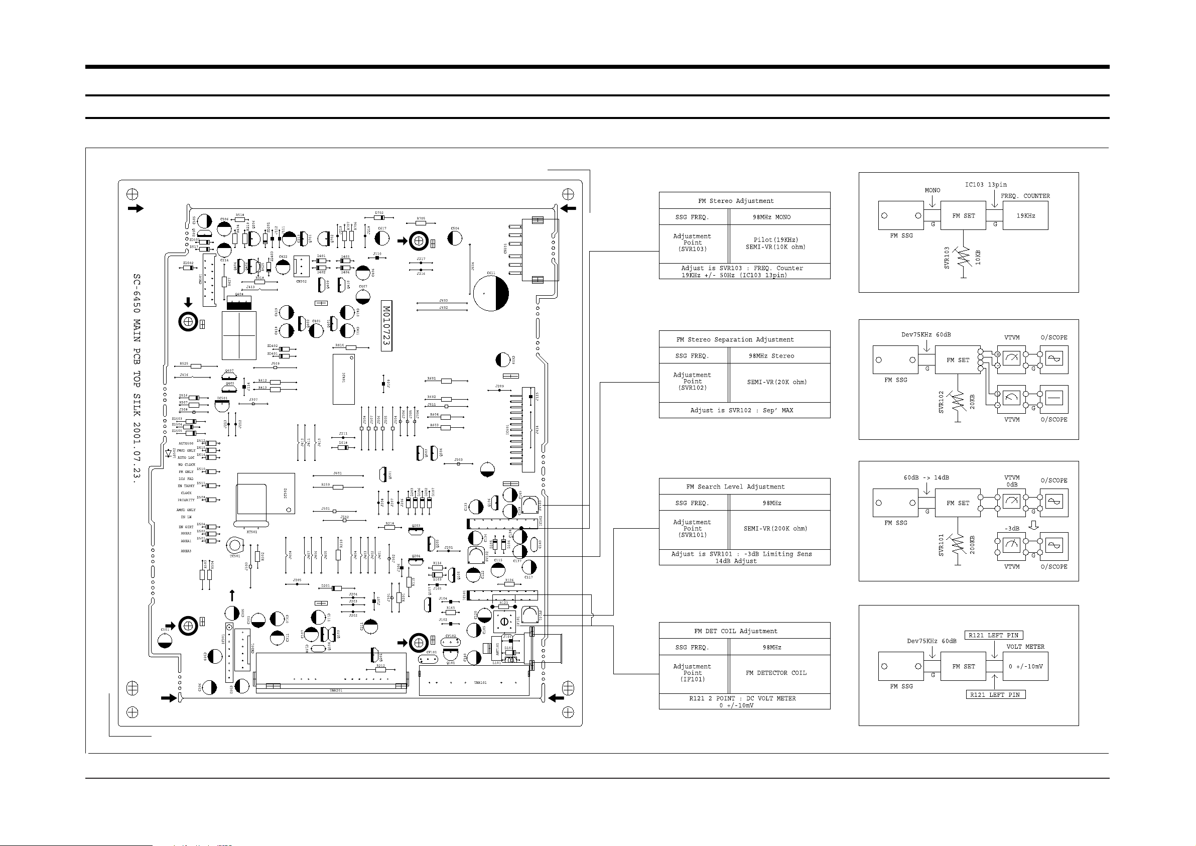
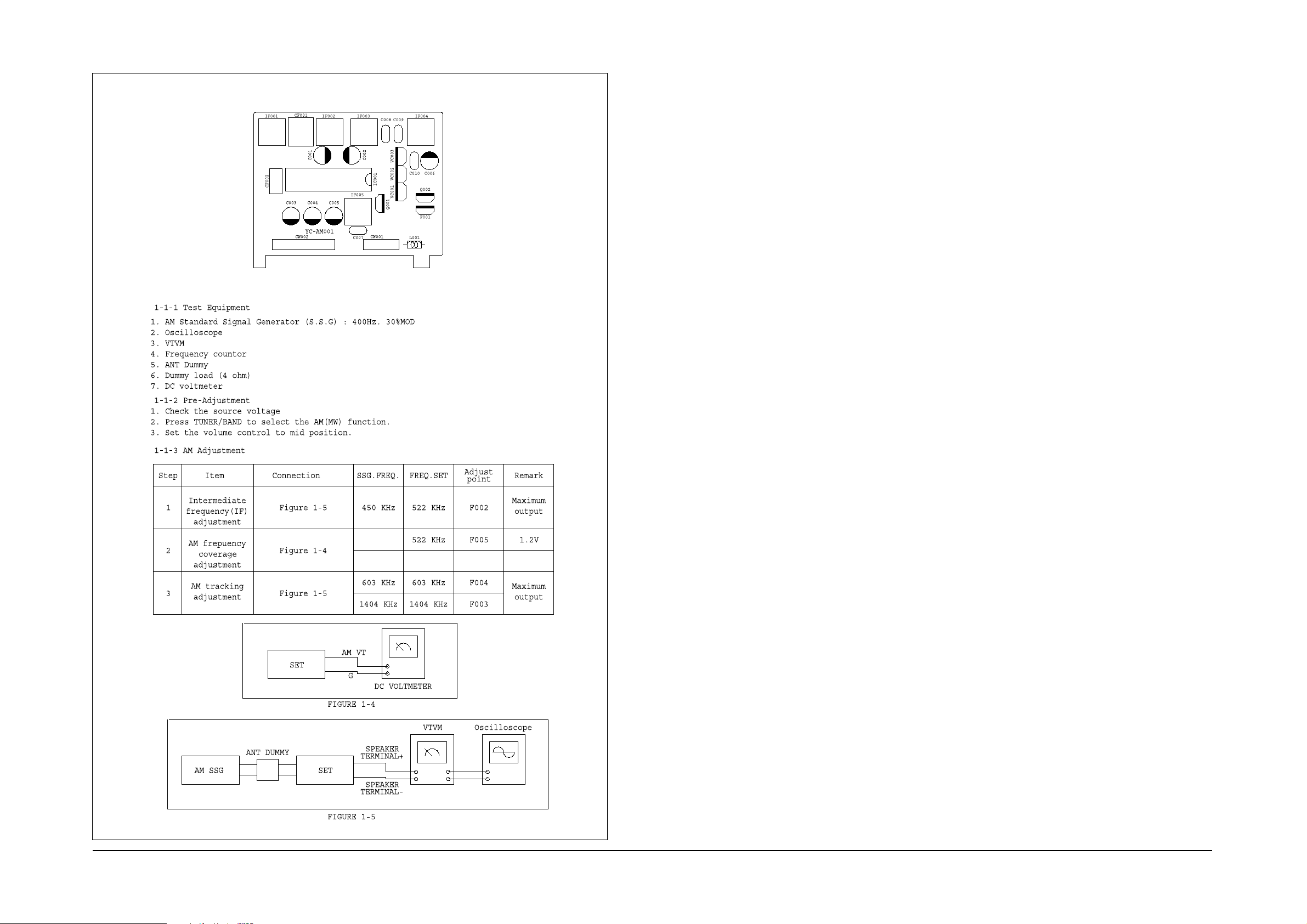
1. Alignment and Adjustments
1-1 Instruction
Samsung Electronics 1-1
1-2 Samsung Electronics
Alignment and Adjustments
Dashboard
Installation
sleeve
Precautions :
ôô
Be careful not to touch the
rear side panel of the unit
when removing the unit from
the installation sleeve, since it
may be hot. On this side the
cooling ribs are located.
ôô
The unit is designed to oper-
ate only on 12 volt DC negative ground electrical system.
ôô
When you replace the fuse, be
sure to use a fuse of specified
amperage for each wire as
mentioned in chapter
“Connections”. Using a fuse of
higher amperage may cause
serious damage to the unit.
Mounting the unit
Notes :
ôô
Use only the parts included
with the unit to ensure proper
installation. The use of
unauthorized arts can cause
malfunctions.
ôô
Consult with your nearest car
audio dealer if installation
requires the drilling of holes or
other modifications of the
vehicle.
ôô
Do not use the front panel as
a way of gripping the unit
during installation and wiring.
The front panel may come
away and the unit may drop
on the floor.
ôô
Periodically wipe the
contacts on the back of the
front panel with a cotton swap
moistened with alcohol.
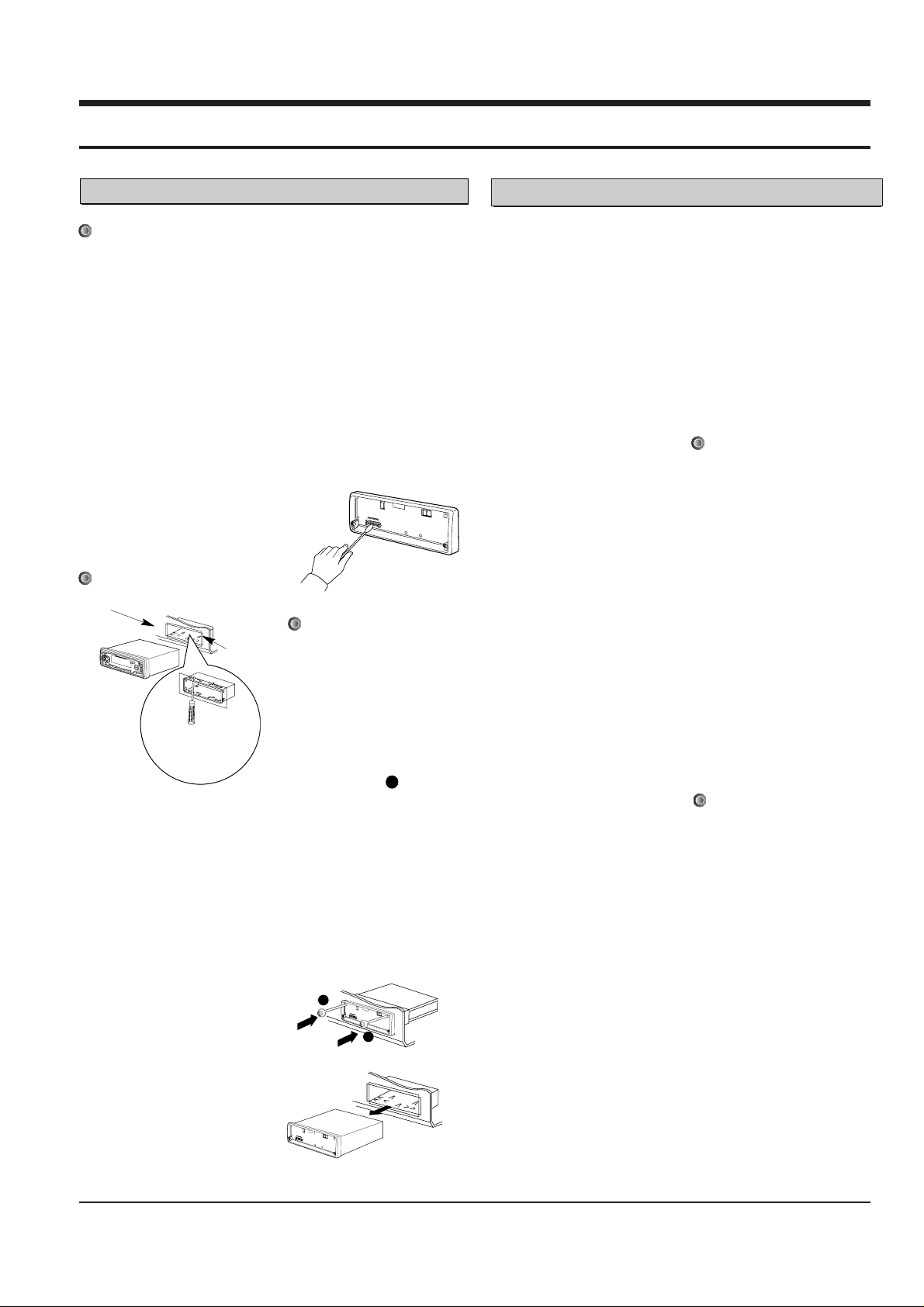
When removing the unit
from the installation
sleeve
If you need to remove the
unit from the installation
sleeve,
proceed as follows.
Œ
Remove the front panel from
the unit.
´
Insert the lever into hole
on one side of the unit, and
pull the lever toward you. Do
the same operation on the
other side and pull out the
other side and pull out the
unit from the installation
sleeve.
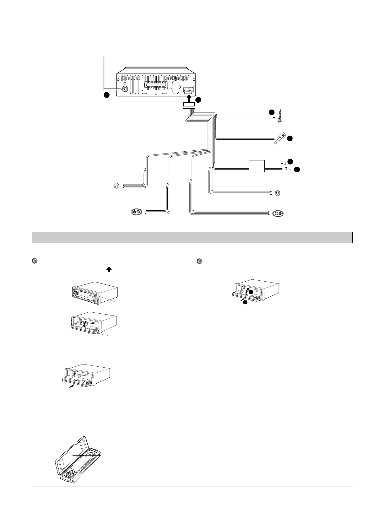
Œ
Main connector
Connect the main connector
to the female connector on
the back of the unit.
´
Antenna Connection
Insert the plug of the car
antenna cable into the jack at
the rear of the unit.
ˇ
Memory Back-up Lead
(Orange)
Connect the orange memory
power supply wire to a 12V+
terminal that is always
supplied with power
regardless of the vehicle’s
ignitions switch position. If
this connection is made
incorrectly or is not made at
all, the unit will not work.
¨
Ground
Connection (Black)
ôô
Connect the ground lead
(black) to a metal part of the
vehicle and secure it using
the screw provided on the
vehicle for this purpose.
ôô
If this connection is loose, or
if the cord is connected to
something other than a metal
part of the car, noise or
malfunction may result.
ˆ
Power Supply Lead (Red)
Connect the red power supply wire to 12V+ terminal
controlled by the car ignition
switch.
Ø
Power Antenna
Lead/External
Amplifier Remote
Turn-on Lead (YELLOW)
Your will find a separate
lead, yellow with a male terminal
suitable to many automatic
antenna. This lead is not to
be used with
non-automatic antenna. If an
automatic car antenna is
used, when connecting the
lead, the antenna will be
automatically extended when
the main switch is turned on.
This can also be used as a
remote turn-on wire
connection for amplifiers that
have a remote sensing lead.
Using this connection will
allow simultaneous turning
on/off of the radio and an
external amplifier.
Precautions
ôô
Do not bring the connecting
cords near parts whose
temperature will rise when
the vehicle is driven.
ôô
Secure the connectors
securely so that they are
locked into position.
Improper connection can
result in noise or hamper
operation.
This car receiver is not designed
to utilize the vehicle’s chassis as
the electrical return path from
the speaker to the radio. Always
use two connector wire between
each speaker and your stereo
unit.
4-Speakers connection
Use 4-8 Ohm impedance speakers. Refer to the following
connections diagram.
Note:
Do not change polarity of spk
connector.
Connections
Installations
A
2-1
2. Reference
Samsung Electronics
Bend the claws
according to the
thickness of the
dashboard.
A
A
YELLOW
ORANGE
FRONT
RIGHT
REAR
RIGHT
REAR
LEFT
FR +
BLUE
RR +
GRAY
RL +
WHITE
FL +
GREEN
FRONT
LEFT
FR -
BLUE/BLACK
RR -
GRAY/BLACK
RL -
WHITE/BLACK
FL -
GREEN/BLACK
Filter Box
In-line Fuse
(10-amp)
Power Antenna
2
6
1
BLACK
3
RED
4
5
Antenna Signal
Antenna Jack
Detachable Front Panel
2-2 Samsung Electronics
The front panel of this unit can be detached to prevent theft.
Detaching the Front Panel
Œ
Press the RELEASE button ( )to release the detachable front
panel.
´
Hold the center part of the front panel and pull it towards you
gently.
Note:
Take care not to put pressure on the display or control buttons, or
drop the front panel.
ˇ
Place the Front panel in the supplied protective case.
Attaching the Front Panel
ôô
Push the front panel against the main unit to reattach it.
Notes:
ôô
When replacing the front panel, do not put pressure on the
display or control buttons.
ôô
The control buttons may not work properly if the front panel is not
attached properly. If this occurs, gently press the front panel.
ôô
Do not leave the front panel in any area exposed to high
temperatures or direct sunlight.
ôô
Do not drop the front panel or otherwise subject it to strong impact.
ôô
Do not allow such volatile agents as benzine, thinner, or insecticides to come into
contact with the surface of the front panel.
ôô
Never try to disassemble the front panel.
Protective Case
Front Panel
RELEASE
Button
2
1
Samsung Electronics
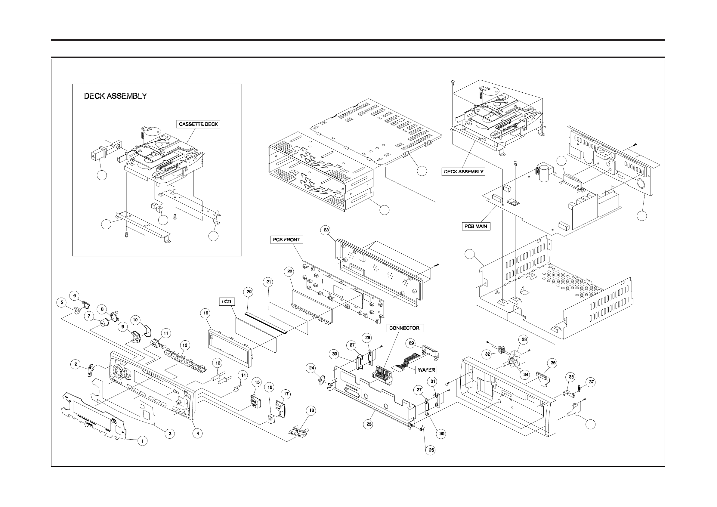
3-1
3.Exploded Views and Parts List
46
45
47
48
43
44
40
41
42
39
 Loading...