

Page 1

Picture tube
SC-528DX. ANALOGUE.
SC-528DXL. ANALOGUE.
SC-528L. ANALOGUE.
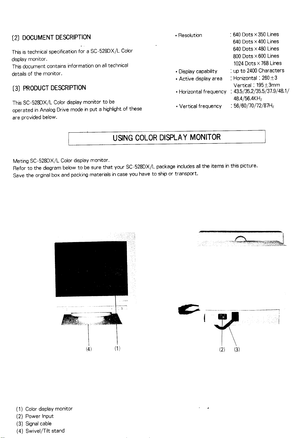
Input signal
Display
Colors
Synchro-
nization
Resolution
Video band
width
Display area
AC Input
voltage
Power
consumption
Dimension
Weight..,,..
SPECIFICATION
. . . . . . . . . . . . . . . . . . . . . . . . . . . . . . . . . . . . . . . . . . . . . . . . . . . . . . . . . . . . . . . . . . M36KUT26XXOl(F)
M36KUT23XXOl
15 Inches diagonal
90 degree deflection,
. . . . . . . . . . . . . . . . . . . . . . . . . . . . . . . . . . . . . . . . . . . . . . . . . . . . . . . . . . . . . . . . . . . . . Video
. .
. . . . . . . . . . . . . . . . . . . . . . . . . . . . . . . . . . . . . . . . . . . . .Any
....
. . . . . . . . . . . . . . . . . . . . . . . . . . . . . . . . . . . . . . . . . . . . . . . . . . . . . . . . . . . . . ..Horizontal
. . . . . . . . . . . . . . . . . . . . . . . . . . . . . . .
. . . . . . . . . . . . . . . . . . . . . . . . . . . . . . . . . .
. . . . . . . . . . . . . . . . . . . . . . . . . . . . . . . . . . . . . . . . . . . . . . . . . . . . . . . . . . . . . . . . Horizontal
. . . . . . . . . . . . . . . . . . . . . . . . . . . . . . . . . . . . . . . . . . . . . . . . . . . . . . . . . . . . . . .
. . . . . . . . . . . . . . . . . . . . . . . . . . . . . . . . . . . . . . . . . . . . . . . . . . . . . . . . . 6OW(MAX.) i_
. . . . . . . . . . . . . . . . . . . . . . . . . . . . . . . . . . . . . . . . . . . . . . . . . . . . . . . . . . . . . . . . . . . . .
. . . . . . . . . . . . . . . . . . . . . . . . . . . . . . . . . . . . . . . . . . . . . . . . . . . . . . . . . . . . . . . . . . . . .
. . . . . . . . . . . . . . . . . . . . . . . . . . . . . . . . . . . . . 640 dots(H) x 350 Lines
~ . . . . . . . . . . . . . . . . . . . . . . . . . . . . . . . 7fjMHz(_3&)
matrix
:
0.7Vp_p Analog level positive
Sync : TTL level
Colors
:
31,5/35.2/35.5/37.9/40,1/48,4/56.4KHz
Vertical : 56/60/70/72/87Hz
640 dots(H) x 400 Lines
640 dots(H) x 480 Lines
800 dots(H) x 600 Lines
1024 dots(H) x 768 Lines
:
260 +3mm
Vertical : 195
AC9OV_264V(47-63HJ
354(W)X364(H)
j4kg(Approx)
(SC-528DX)
(F) (SC-528DXL)
0.28mm
*3mm
10%
X4OO(D)mm
dot pitch, black
Page 2
Page 3

1. GNEERAL INFORMATION
(1) SAFETY PRECAUTION
WARNING : Service should not be attempted anyone untamilliar with the necessary precautions on this unit.
The following precautions are necessary during servicing.
1. Some parts such as a picture tube in this unit have special
safety-relate charateistics for X-RAY RADIATION protection.
For continued safeth, the parts replacement should be undertaken referring to item 2 below.
2. Many electrical mechanical parts in this unit have special
safety-related characteristics for protectron against shock
hazard and others.
These characterstics are often passed unnoticed by a visual
inspection and the protection afforded by them cannot necessarily be obtained by using replacement components rated
for higher voltage wattage, etc.
Replacement parts which have these special characteristics
are identifide in the manual and supplements by shading on
the schematic diagram and the parts list.
Before replacing of these components read the parts list in
this manual carefully
3. When replacing chassis in the cabinet, always be certain that
all the protective devices are installed properly, such as insulating covers, strain relief, etc.
4.
Before replacing the back cover of the set, thoroughly
spect
inside the cabinet to see that no stray parts or tools
in-
have been left inside.
5. Before returning the set to the customer always perform
an AC leakage current check on the exposed metallic parts
of the cabinet, such as terminal, screwheads, metal overlays,
control shafts, etc, To be sure the set in safe to operate
without danger of electrical shock, Plug the AC
rectly into a
transformer during this check). Use an AC voltmenter
having 5000 ohms per volt or more sensitivrty in the following
manner.
Connecta 1500ohm, 10watt
(PF),
ground (water pipe, conduit, etc.) and the exposed metallic
parts, one at a
Measure the AC voltage across the combination of 1500
ohm resistor and
plug at the AC outlet and repeat AC voltage measurements
for each exposed metailic part.
Votage
sponds to
tutes a potential shock hazard and must be corrected
diately.
115V
AC aoulet (do not use a line isolation
resistor, paralleled by a
250VAC capacitor, between a known good earth
time.
O.l5mfd( /IF)
measured must not exceed
0.2mA
AC any value exceeding this limit
capacitor, Reverse the AC
0.3V
RMS. This corre-
lrne
cord
0.15mfd
constr-
imme-
diL
MONITOR
0.15~
F
Place this
a water pipe, conduit etc.
proge
on each
Vdtrneter
Hook-up
250V AC
for leakage Current
(50000hm per volt or more
Reading should not exceed
Good earth Qroud such as
exposed metallic part
chebc
sensitivrty)
0.3V.
“-_
.
Page 4
Page 5

(4) User ADJUSTMENTS
Side
Power switch
Contrast
Brrghtness
Vertical Position
Horizontal Position
Height
Width
Side-Pincushion
Degauss
Turn the display on and off with this switch.
0 : Turn off,
Adjusts the white level of the image, It sets the contrast
between the light and dark portions of the Image.
Adjusts the black level of the image, It sets the overall brightness.
Adjusts the vertical position of the image, The image should be centered on the screen.
Adjusts the horizontal position of the image. The image
Adjusts the vertical height of the image. The vertical image size should be approximately 195mm.
Adjusts the horizontal width of the image. The horizontal image size should be approxjmately 260mm.
Adjusts the left and right sides of the image. The irnage should be a rectangle.
Removes the color impurities which can appear on the screen after longtime use. It is automatically
activated when you turn on the
I :
Turn on
display.
shouki
be centered on the screen.
Page 6

2. CHARACTERISTICS
[l]
GENERAL CHARACTERISTICS
NO
1
CDT (Color Display Tube
2
CDT Phosphor
D.Y
3
4
5
6
7
8
9
10
[
2) Electrical Characteristics
Deflectron Angle
Resolution
Sync. Frequency
Input Signal
AC Input
Display Color
Drsplay
Display Character
Detiption
Zone
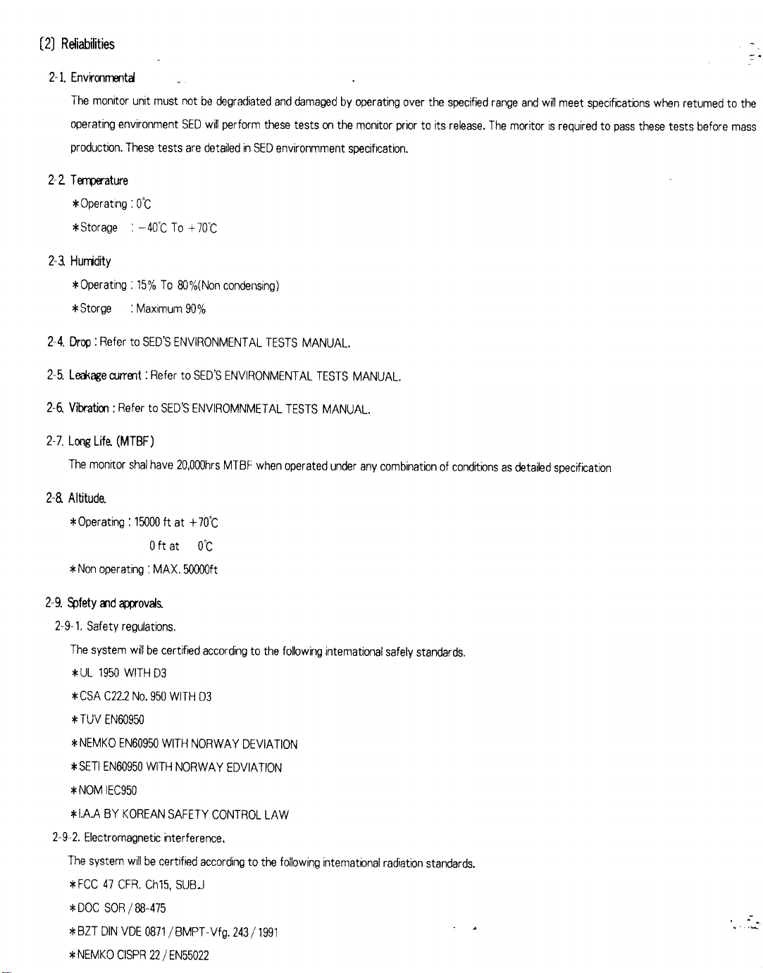
2-1. Input Power
Nominal Remark
)
M36KUT26XXOl
M36KUT23XXOl
P 2’2 Dark Phosphor
90”
80Ox600/1024x768Lines
H
:
31.5/35.2/35.5/37.9/48.1/48.4/56.4KH/
V :
56/60/70/72/87Hz
R.G.B
Analog
9OV -
264V
Unlrmrted
H :
260mm,
Up To 2400 Characters
(F) :
SC528DX
(F) : SC-528DXL
v : 195mm
TOSHIBA
WITH ASN
WITH VLF.
Graphic Mode
Free Voltage
NO --
1
2
3
The
drsplay
device shall
Description Nominal
Power Source
Frequency
Power Consumption MAX.
maintarn
the specified performances in the range described below.
AC
9OV -
47-63Hz
8OWilO%
264V
Remark
Universal Power
Page 7

2-2
Input signal
The input signals shall be applied to the display devices through a signal cable
tor. (Rof. Fig 1 Timing chart)
Section
Desaiption Nominal
which
must be intemeded as part of the moni-
Remark
Video
Signal
Red
Green
Blue Input impedance 75 Ohms
Horizontal Frequency 31.5/35.2/35.5/37.9/48.1/48.4/56.4UH~
-Sync.
Vertical
-Sync
Video input
Polarity Positive
Pixel Rate
Rise/Fall Time Less than 8 nsec
Sync input
Pulse Width
Front Porch
Back Porch
Sync Input
Pulse Width
Frecuency
Front Porch 0.014-1.2
Back Porch
0.0 to
0.7Vpr
Analog
Up to 75
2.4 6 Level 6 5V
1.2-3.92psec
0.18-1.12psec
1.25-4.6 p
2.4V ZZ
0.06-0.2msec
56/60/70/72/87H~
0.48-1.88
MHz
set
Level 6 5V
msec
msec
-
_
_
2-3.
CRT Electrode voltage
NO
1
Heater
2
3
4
5
6
Cathode( R.
Gride
Gride
Gride $3
Anode Voltage
G. B)
#I
@
Description
6.3V i 0.5V,
80V f 20V
ov- -70v
600V + 1
6.5kV
24kV
+0.5kV
I!I
1
OOV
kV@OuA
Nominal
300mA
i-
30mA
RGf?X3rk
Screen
Focus
-__
Page 8

2-4. Timing
Ct-wactristic
The monitor shall be capable of displaying 5 different vertical resolution within the scan frequencies as well as the scanning
mode. (REF. FIG 1 TIMING CHART)
-,
(3ilM;$tNICAL
The total weight shall be approximate 14kg.
32
Exter
Width
Height
Length
33. Tilt/Swivel
The inclination of the
must be min. 180deg.
34. Tool Resin
TOd
I
Front
CHARACTERISTICS
nal Dimensions(n-rn)
Without Stand
354
335
400
suface
I
I
Resin
KJU
of the screen shall be adjustable at least -5deg. With a
With Stand
354
364
400
I
1
PARCHMENT WHITE
color
min. ldeg
from the
wertrcal.
The swivel
I
1
Rear
I
Stand
I
KJU
1
PARCHMENT WHITE
1
PARCHMENT WHITE
1
1
Page 9

3. SERVICE ADJUSTMENT
+B
VOLTAGE ADJUSTMENT
$
Receive a cross-hatch pattern signal of 640 x 400 mode.
*Adjust contrast and brogtitness controls to maximum.
$
Adjust G2 control to minium.
*Make sure the AC power supply voltage is at the specified value.
*Adjust VRlOl(
HIGH VOLTAGE ADJUSTMENT
138.5V
line-ADJ. volume) for +b voltage equal to
.
138.5i-0.5V.
*Receive a cross-hatch pattern
*Adjust
VR102( +B controler)
stgnal
of 640 x 400 mode.
for the voltage of pin No.2 of FBT equal to 68f0.5V.
HORIZONTAL DEFLECTION CIRCUIT ADJUSTMENT
Horizontal
31.
*Disconnect the signal cable from signal source.
*Adjust
*The horizontal frequency for other modes are automatically set by interface circuit.
Horizontal position adjustment. (H-SHIFT)
32
*Receive a cross-hatch pattern signal of 800 x
*The picture is to be placed at the center position of the CDT screen by sdjusting
Horizontal
33.
*Adjust contrast and brightness controls to maximum.
*Receive a cross-hatch pattern signal. (800 x 600 mode
*Adjust
oscillation Frequency
VR302(horizontal
bottom side of front.
width adjustment. (H-WIDTH)
VR902(
H-WIDTH control) located at the bottom side of the front, for the H-SIZE equal to 260mm.
adjustment(H-HOLD)
frequency control) for the horizontal frequency equal to
600( 37.9kHz, 60HZ)
37.9kH, 60Hz)
mode.
4. VERTICAL DEFLECTION CIRCUIT
4-1.
Vertical oscillation frequecny adjustment.
*Disconnect the
$
Adjust VR305(VHOLD2) control to maximum value of resistance.
*Adjust VR301 (V-HOLDl) for the vertical frequency equal to 48i0.5H,
*
Receive a cross-hatch pattern signal of 800 x
*Adjust VR903 located at the bottom side of the front for the V-SIZE equal to 195mm.
*Receive a cross-hatch pattern signal of 640 x
*Adjust VR305(VHOLD2) for the V-SIZE equal to 195mm.
4-2
Vertical linearity
*Receive a cross hatch pattern signal.
$
Adjust the size volume so that the height becomes 195mm.
*Adjust V-LIN volume( VR303) for optimum linearity.
4-3.
Vertical size adjustment
*Receive a cross hatch pattern
*Adjust
4-
4.
Vertical position adjustment (V-SHIFT)
*Receive a cross hatch pattern
*The picture is to be placed at the center position of the CDT screen by adjustiong
VR903(SIZE
bottom side of front.
signal
cable from signal source.
adjustmt(V-LIN)
control) located at the bottom of the front for the height of the pattern equal to 195mm.
(V-HOLDI, V-HOLD2)
600(37.9kHL, 60HL)
480(37.9kHZ 72H/)
(37.9kHz 60Hz
srgnal. (37.9kHz 60HL
signal.
(
37.9kHZ 60HZ
mode.
mode.
mode)
mode)
mode)
31.5i0.2kHL
VR904(H-SHIFT
VR905(
4
control) located at the
V-SHIFT control) located at the
Page 10
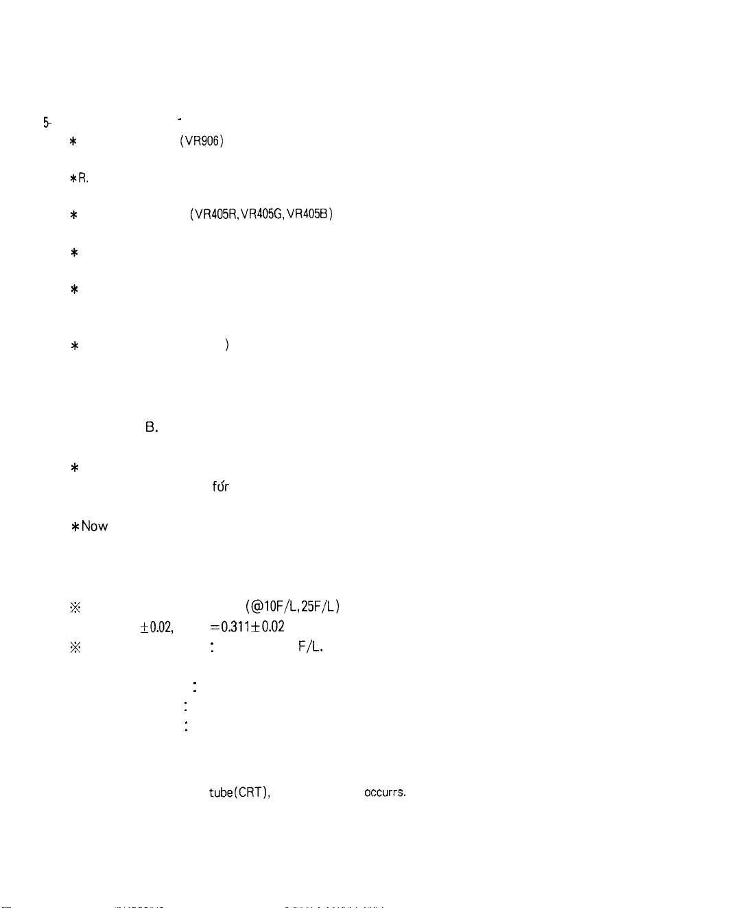
5. VIDEO CIRCUIT ADJUSTMENT
5
1. Controls function
$
Brightness volume
This knob controls the black level of the image.
*R.
G. B gain volumes (VR401, VR402, VR403)
These volumes control the gain of RED, GREEN, BLUE video pre-amplifier.
I
R. G. B. bias volume
These volumes control the bias voltage of RED, GREEN, BLUE cathode of CDT.
$
Screen volume (On the FBT)
This volume controls the screen voltage of the CDT.
*
Cpmtrast Golume (VR907)
This knob controls the contrast of the image. It establishes the gain of the video amplifier but does not affect the raster
luminance.
$
Focus volume. (On the FBT
This volume controls the focus of the picture.
_
(VR906)
(VR405R, VR405G, VR405B)
)
6. WHITE BALANCE ADJUSTMENT
*Adjust R. G. 6. gain and bias volumes to mechanical center.
*Operate the set for 15 minutes to warm up.
*
Degauss the CDT face fully with degaussing tool.
*Adjust screen volume
*Adjust bias volume of R. G. B so that the color of the raster may becomes white.
*Now
adjust the screen volumes for the luminance of the raster equal to 1.0 F/L MAX. (without wideo signal)
*Receive a full white pattern signal.
*Adjust R. G. B gain volume for the specified white color.
Use the color analyzer equipment.
%
Standard Color coordinate. (@lOF/L,
X = 0.281
%
Maximum brightness : More than 25
l With full white pattern.
l Brightness V/R
l
Checking area : Center of display.
l Contrast V/R
kO.02,
fo’r
the luminance of the raster equal to l-3 F/L.
Y
=0.311 kO.02
:
Set to raster cut off.
:
Set to maximum.
25F/L)
F/L.
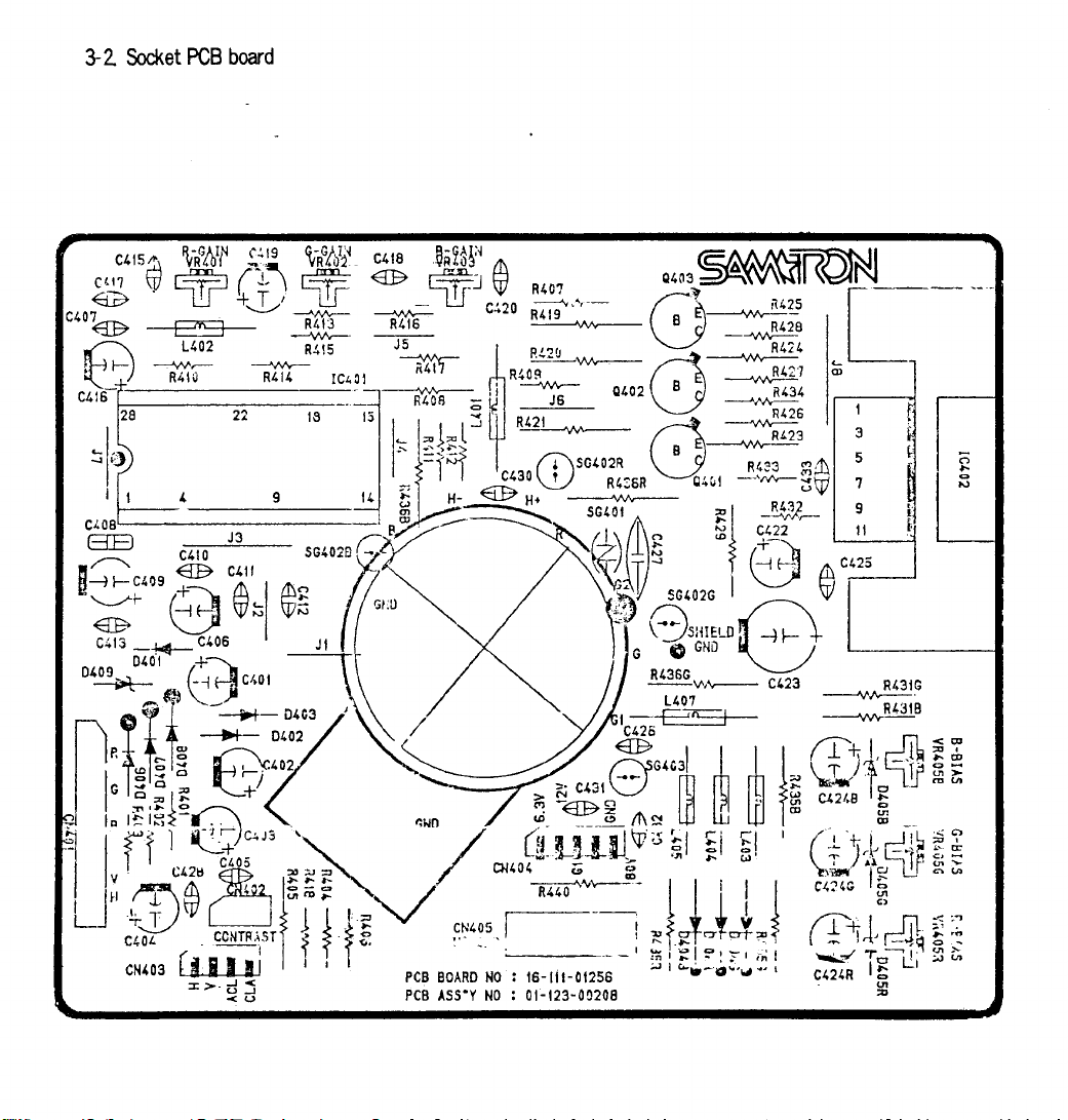
7. FLASHOVER PROTECTION
Due to the high voltage in this tube(CRT), internal flashover
flashover from destroying the cathode or other internal circuits.
These spark gaps shall be connected with each electrode in socket PCB assembly.
occurrs.
Protection must be provided using spark gap to prevent
Page 11
Page 12

Page 13

Page 14
Page 15
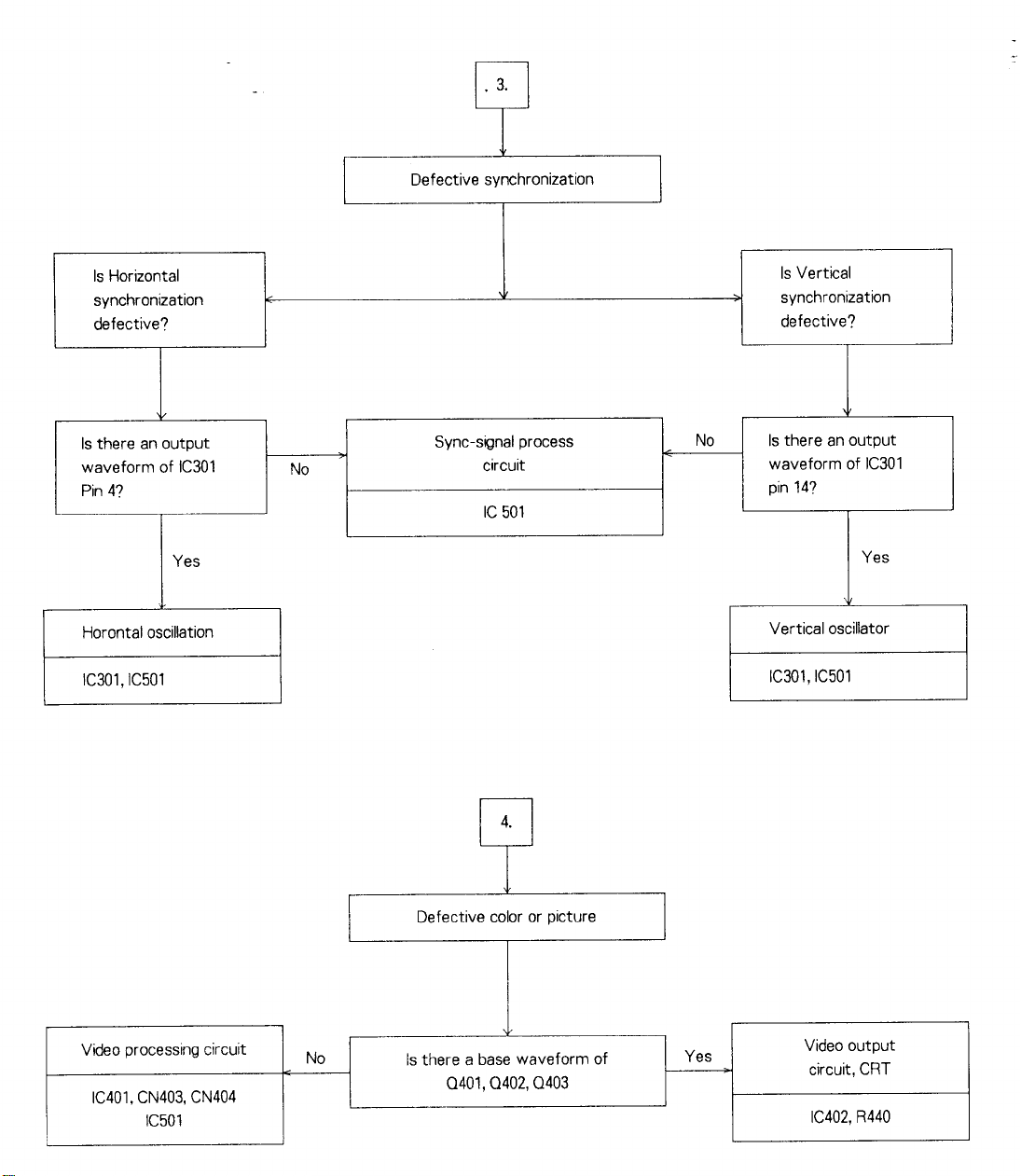
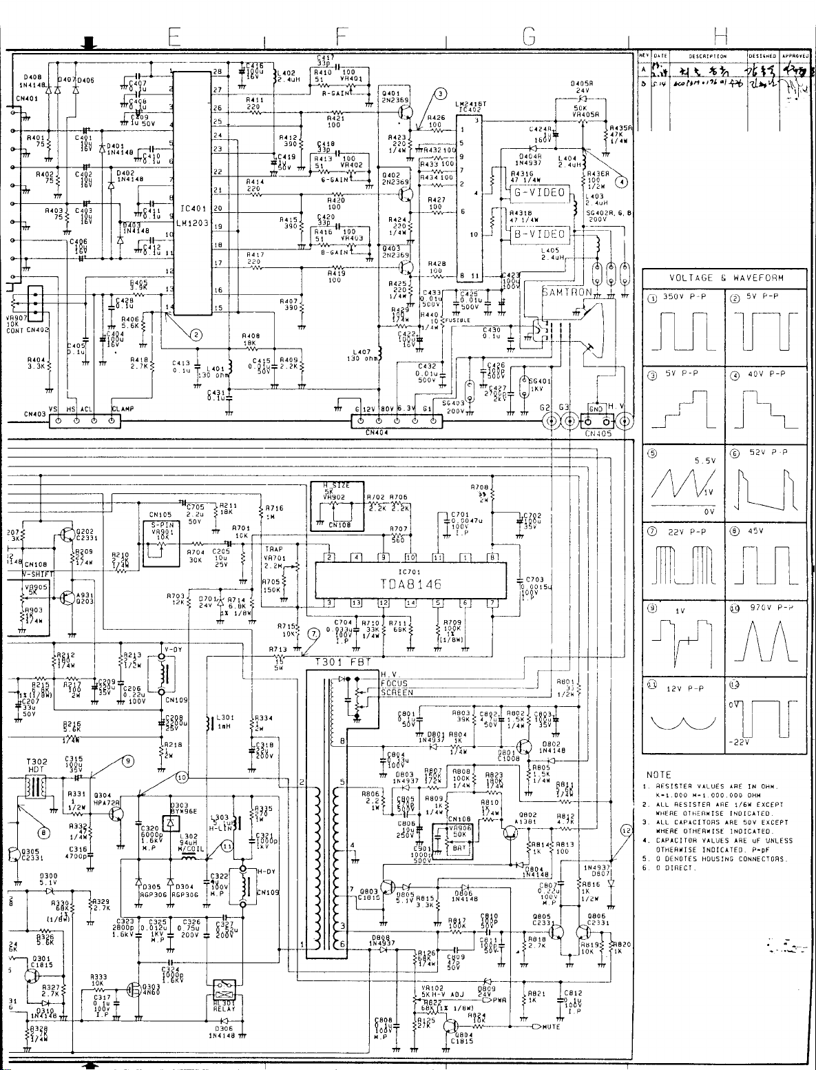
5. THEORY OF OPERATION
GENERAL
1.
The circuit of this monitor could be devided into four sections.
One of them is power supply section, and the others are the-interface, sweep video, and CDT drive section.
POWER CIRCUIT
2
The switching mode power supply is adopted for this circuit.
The chassis (secondary side) is insulated from the power source (primary side) by the transformer
By the winding of the transformer TlOl connected to the collector of
cuit, the ICI01 is submitted to negative feed back and it operates as a blocking oscillator.
When the voltage of power source or load
IClOl.
When the voltage applied to pin2 is varied, the conducting time of IClOl is varied to compensate output voltage for the change.
Which makes output voltage of
The range of operating frequency is
+B Voltage regulator drcuit
3.
1~103
is a regulator for
comes from FBT pin6 and outputs signals with different duty times and frequencies.
there signals drive
controling
IC103
TlOl
stabilized.
+B Voltage of each mode supplied to
to control the adjusment of +B Voltage of each mode to
curredt
22kHz-70kHz.
is varied, it is detected by the winding and the voltage is applied to pin2 of
IClOl
and the other winding connected to the control cir-
FBT(T301)
pin2.
ICI04
FBT Pin2.
TlOl.
detects the Level of Pulse which
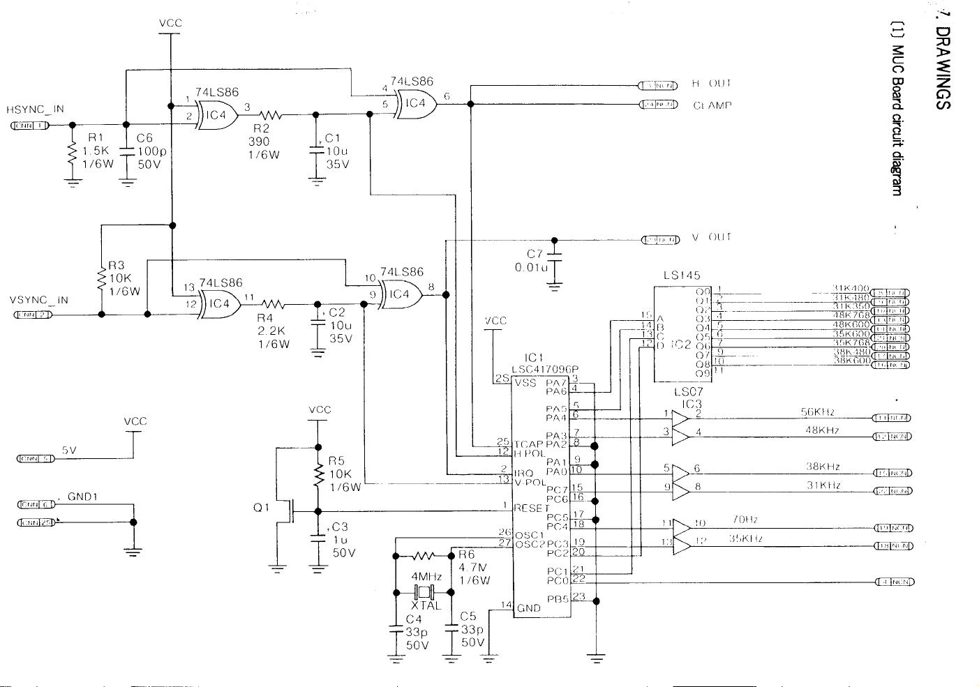
Interface circuit
4.
This is a circuit for detecting the polarities and frequencies of the sync. pulse from computer, and for the automatic control of
each mode.
It uses Micro controller unit, which has three functions as follows.
*
MCU identifies each mode by processing the received frequency and polarity of the sync. from computer.
*MCU
controls buffer and decoder IC to output proper signal for picture size, frequency, and picture position.
*When monitor is turned on or mode is changed, mute function is operated.
VIDEO DRIVE CIRCUIT
5.
The R. G. B input signals with analog level are applied to the pre-amplifrer LMt203.
This section amplifies the output signal of a generator enough to dirve a video output circuit.
Video gain is controlled by the DC voltage of pin12 and DC bias is controlled by the DC voltage of the pin 15, 19 and 24.
Clamping pulse is applied to pin14 through IC
VIDEO OUTPUT CIRCUIT
6.
The
LM2416T
The
LM2416T,
It is designed to swing large voltage n a short duration.
The dirven signals are applied tp CDT cathodes.
DEFLECTION CIRCUIT
7.
IC has 3 channels of R. G. B in one chip.
the CRT video dirver,
IS
502(MCU
a large signal amplifier with wide bandwidth.
IC).
This circuit has two
cal power amplifier.
KS. IC301
is a monolithic IC for horizontal and vertical sync processing. And
IC201
is a monolithic IC for verti-
Page 16
7-
1. Vertical Deflection Circuit.
The
vertrcal
sync. signal with negative polarity is applied to pin 14 of IC 301. The vertical frequency of the oscillator can be
controlled by the voltage at pin 12 of IC 301. And it canbe varied vy adjusting V-HOLD volume
The vertical
The vertrcal linearity is controlled by the voltage at pin 17 of IC 301.
The ramp
The IC 201 is a power
Vertical position is determined by the DC
adjusting V-SHIFT volume(VR905).
Horizontal Deflection Circuit.
7-2
The horizontal sync. signal with negative polarity is applied to pin4 of
controlled by the voltage at pin 1 of IC 301. And it can be varied by adjusting H-HOLD volume
The flyback pulse is fed to pin 8 of
The phase of horizontal saw-tooth wave is compared with that of fly back pulse and
the
IC301.
By adjusting H-phase control(VR904) the horizontal position of picture is varied. The horizontal frequency oscillation is obtained from pin3 of
The horizontal output
anode and focus vollages as well as several secondary supplies.
A
diode
SlDE
PlNCUSt-liON CORRECTOR
herght
is controlled by the voltage at pin 16 of
srgnal
from pin 15 of IC 301 is applied to pin 1 of IC 201.
amplifier.
cuttent
flowing through vertical DY. So the picture is shifted to top or bottom by
IC302
for AFC(Automatic Frequency Control).
IC302
and is fed to the next horizontal drive circuit.
circurt
uses a resonant
modulator circuit IS used for east/west correction and for setting horizontal size.
flyback
IC301.
IC301
The horizontal frequency of the oscillator can be
system to drive the deflection yoke that generates the anode the
horrzontal
(VR301,
(VR302).
sync.
VR305)
srgnal
at AFC circuit of
Thus
circuit compensates the east/west distortion.
The signal processing for east/west correction
The vertical ramp signal from the
The output section of
A positive horizontal
The horizontal width is determined by the voltage of
(VR902).
IC701
flyback
IC301
is a class-D(PWM) power amplifier.
pulse from T301 is divided by resistor R703 and applied to pin 9 of
IS
done in
is AC coupled through
PROTECTION CIRCUIT
If a failure,
voltage of D300 will be Increased by the FBT(T301).
Then the protectron
When thes happens, the
Therefore In order to restart
whrch
causes high voltage increased, occurrs(such as opened sweep capacitor or failed power regulator), the cathode
occurrs
by
turnrng
on Q301 as a result of the breakdown of
oscrllator
signal coming from
operatron,
the monitor must be turned off and on agaim.
IC701.
C205
to the east/west distortion amplitude control,
IC701.
pinl0,
which is varied by the setting of the gorizontal width control volume
D300.
IC301
can no longer dirve Q305. then the set is turned off.
VR901.
Page 17

Page 18

Page 19
Page 20

Page 21

Page 22

Page 23
Page 24

Page 25

Page 26

Page 27

Page 28
Page 29

Page 30

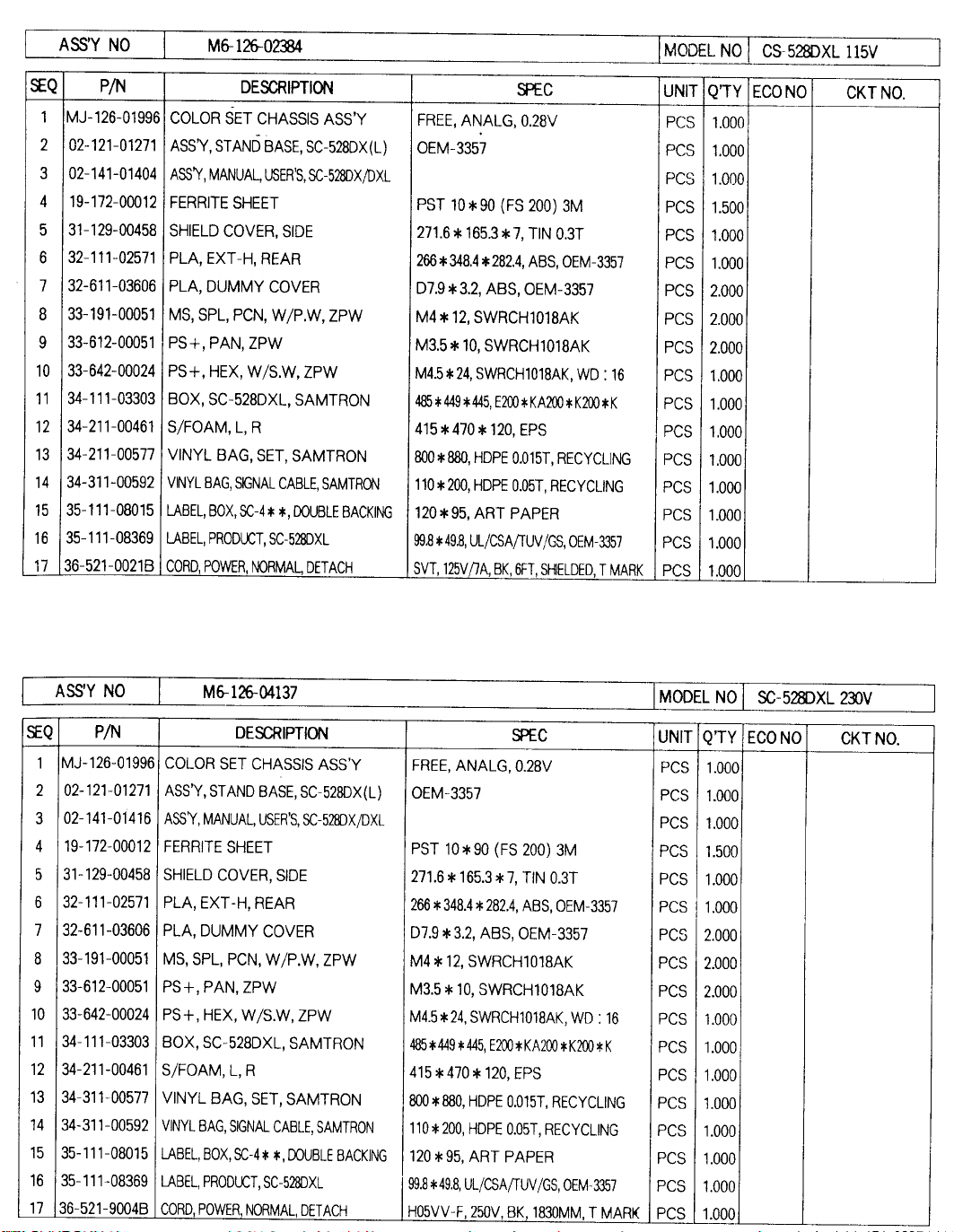
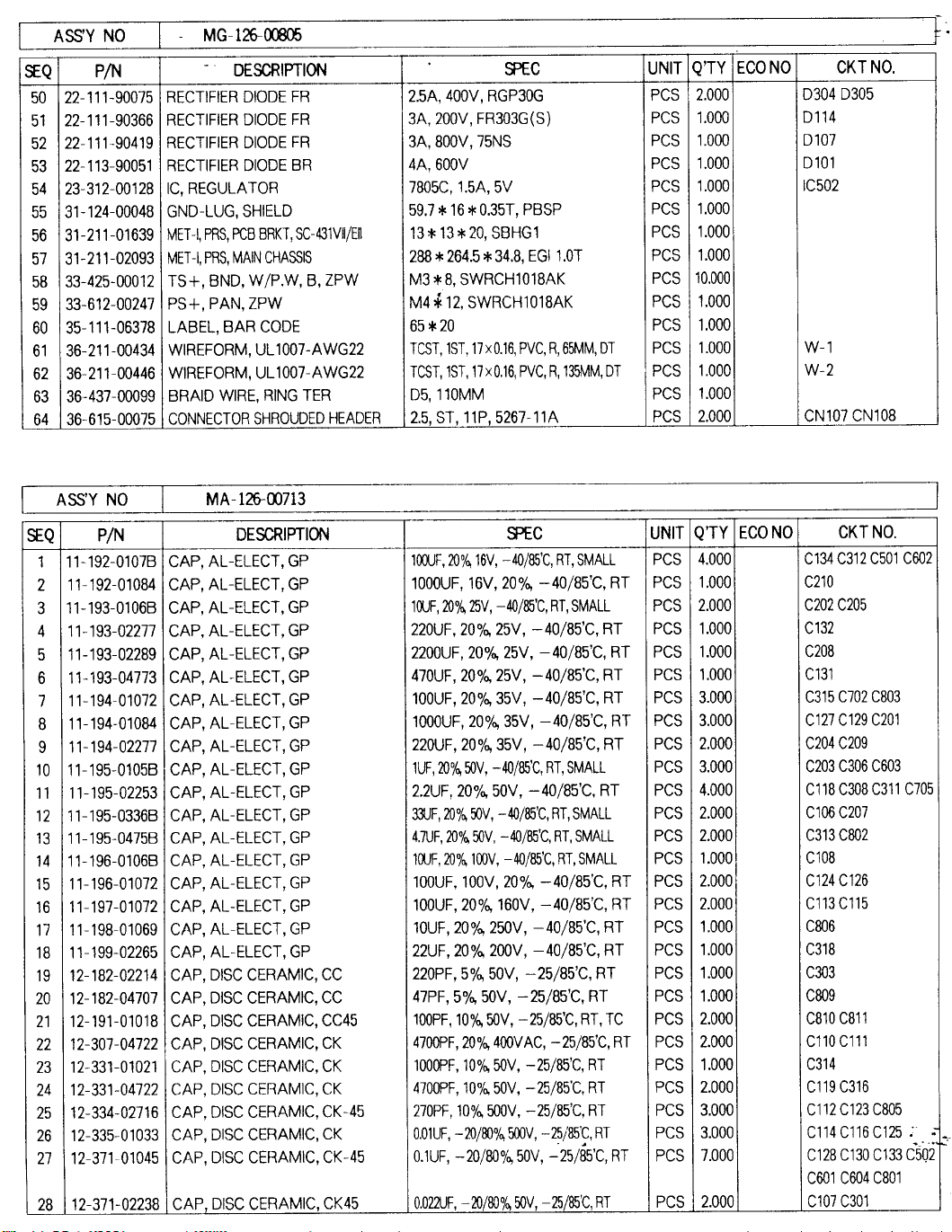
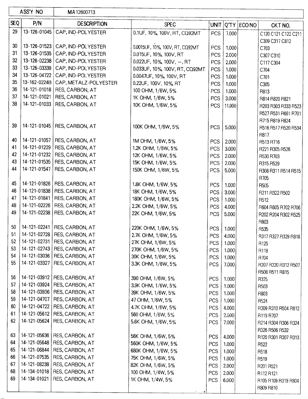
8. APPENDIX
(11
Part List
TABLE OF CONTENTS
NO
l-l
1-2
2
3
4
5
6
7
8
9
10
11
B.0.M STRUCTURE
M6-125-02372
M6-125-02369
MJ-125-01719
02-121-01271
MG-125-00805
01-143-00087
01-151-00553
01-191-00167
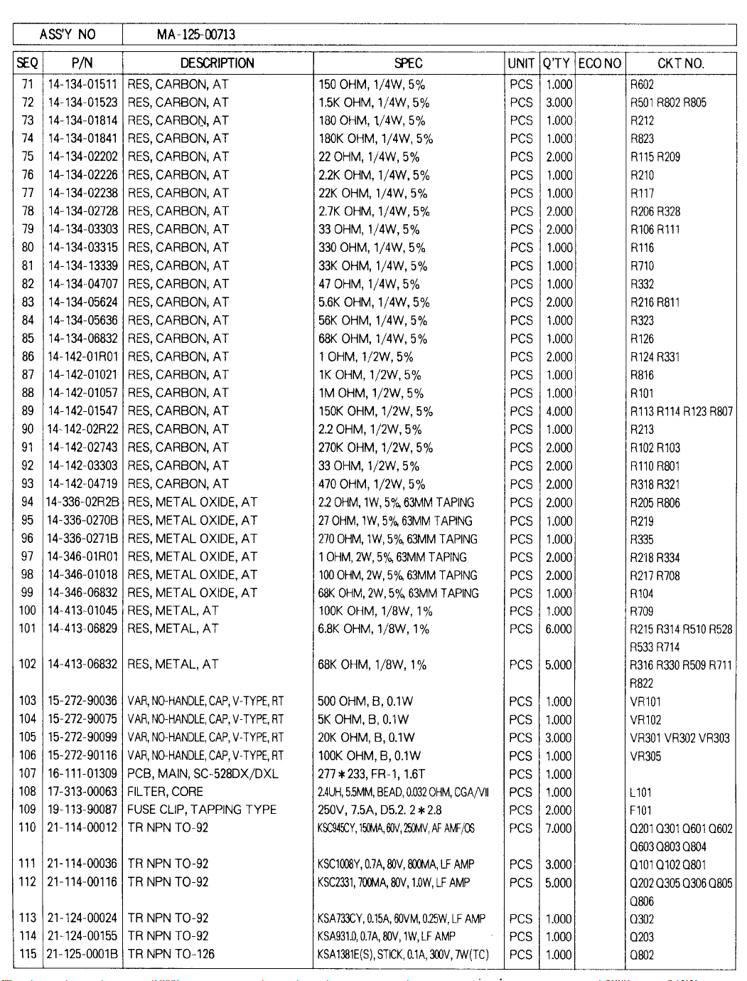
MA-125-00713
01-123-00223
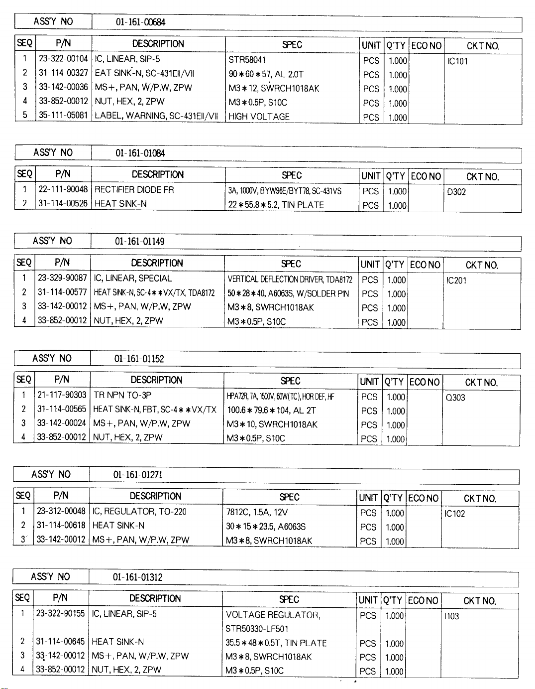
01-161-00684
01-161-01084
ORIGINAL REMARK
15
15
18
2
__
63
3
16
2
129
18
5
2
SC-528DX 115V
SC-528DX
ASS'YSTAND
SUBASS'YROCKERS/W
SUBASS'YVOLUME
SUBASS'YACSOCKERW/WIRE
SUBASS'YCPTSOCKER
SUB ASS'Y HEAT SINK
SUB ASS'Y HEAT SINK
230V
12
13
14
15
16
17
18
19
20
01-161-01149
01-161-01152
01-161-01271
01-161-01312
01-161-00179
MA-125-00009
MA-125-00696
01-161-01137
01-162-00048
4
4
3
4
19
11
24
4,
SUB ASS'Y HEAT SINK
SUB ASS'Y HEAT SINK
SUB ASS'Y HEAT SINK
SUB ASS'Y HEAT SINK
SUBASS'YMISCPCB
A/S ASS'Y SOCKET RADIAL
A/SASSY SOCKET AXIAL
) ~~~I~~~~~IZ~~~VER
Page 31

Page 32

Page 33

Page 34

ASSY NO
XQ
8 15-351-00099 VAR, HANDLE, PCB-MOUNT, V-TYPE
9
10
11
12
13
14
15
16 36-431-00208 WIRE, RING TER, SINGLE
P/N
16-111-01229
19-131-90128
22-152-00075
32-611-03514
36-412-00725
36-415-00366
36-431-00104
Ol- 151-00553
DESU?lPTlON
PCB, VOLUME
PUSH
SWliCH
LED, GREEN
PLA, V/R KNOB
WIRE,
CONN/HOUSING
WIRE,
CONN/HOUSING
WIRE, RING TER, SINGLE
SFEC
50K OHM, B, 0.1 W, 20F
207*31,.FR-1,
DPDT, 0.3A,
25MA, 75MW, SLR-34MG3,
D18*
11.5, ABS, OEM-3357
170MM,
420/140/270MM, 8P,
BK,
D5,53MM
G/Y, D4.3, 150MM PCS 1.000 GND
llP,
__-
1.6T
30VDC,
W, 2.5,
W,
6PIN
ROUND
1007$26
2.5,1007 #26
UNIT Q’TY ECONO
PCS 2.000 VR904 VR906
PCS
1.000
PCS
1.000
PCS
1.000 LED
PCS 7.000 VR901
PCS
1.000
PCS
1.000
PCS
1.000
D-SW
CN901
CN902
D-GND
J
CKT NO.
-VR907
AS!S’Y
NO
SEQ
1 17-314-00063 FILTER, EMI SOCKET
a
2 39-422-00024 TUBE-SHRINK, WHT
r-
I
r-
LQ
1
2 11-192-01084 CAP, AL-ELECT, GP
3 11-193-01068 CAP, AL-ELECT, GP
4
5 11-193-02289 CAP, AL-ELECT, GP
6 11-193-04773 CAP, AL-ELECT, GP
7 11-194-01072 CAP, AL-ELECT, GP
8 11-194-01084 CAP, AL-ELECT, GP
9
10
11 1 l-195-02253
12 II - 195-03368
13 11-195-04758
14
15 11-196-01072 CAP, AL-ELECT, GP
16 11-197-01072 CAP, AL-ELECT, GP
17 11-198-01069 CAP, AL-ELECT, GP IOUF,
18 11-199-02265 CAP, AL-ELECT, GP 22UF,
19 12-182-02214
20 12-182-04707
21 12-191-01018 CAP, DISC CERAMIC, CC45
22 12-307-04722
23 12-331-01021
24 12-331-04722
25 12-334-02716 CAP, DISC CERAMIC, CK-45
26 12.-335-01033 CAP, DISC CERAMIC, CK
27 12-371-01045
28 12-371-02238
29 13-126-01045 CAP, IND-POLYESTER
P/N
ASSY
NO
P/N
11-192-01078
1
l- 193-02277
1 l-
194-02277
ll-195-01058
ll-196-01068
CAP, AL-ELECT, GP
CAP, AL-ELECT, GP
CAP, AL-ELECT, GP
CAP, AL-ELECT, GP
01-191-00167
DESCRlF’TlON
MA- 125000713
!
DESCf?lPTlON
CAP, AL-ELECT, GP
CAP, AL-ELECT, GP
CAP, AL-ELECT, GP
CAP, AL-ELECT, GP
CAP, DISC CERAMIC, CC
CAP, DISC CERAMIC, CC
CAP, DISC CERAMIC, CK
CAP, DISC CERAMIC, CK
CAP, DISC CERAMIC, CK
CAP, DISC CERAMIC, CK-45
CAP, DISC CERAMIC, CK45
SW
250V/3A, 473PF(Xl), 2ZPF, 12MH,
D4, POLY-OLEFIN M
SPEC
looUF, 20% 16V, -40/85’C,
lOOOUF,
16V,
20% -40/85’RT
lWF, 20% 25V, -4O/f!5%,
22OUF, 20% 25V, -40/85’C,
22OOUF, 20% 25V, -40/85’C,
47OUF, 20% 25V, -40/85’C,
lOOUF, 20% 35V, -40/85’C,
lOOOUF, 20% 35V, -40/85’C,
22OUF, 20% 35V, -40/85’C, RT
IW, 20% 5%‘, -45/85’C,
2.2UF,
20% 5OV, -40/85’C,
33UF, 20% 5oV, -4O/85%,
4.7UF, 20% 5oV, -40/85’C,
loUF,
20%
l&IV, -40/85’C,
lOOUF, IOOV, 20% -40/85’C,
lOOUF, 20% 16OV, -40/85’C,
20% 25OV, -40/85’C,
20% ZOOV, -40/85’C,
22OPF, 5% 5OV, -25/85’C,
47PF, 5%
lOOPF, 10% 5OV, -25/85’C, FIT,
47OOPF,
20%
lOOOPF, 10% 5OV, -25/85’C,
47OOPF, 10% 5OV, -25/85’C,
27OPF, 10% 5OOV, -25/‘85’C,
O.OlUF, -20/m% !&IV, -25/85’C,
O.lUF, --20/8Oo/, 5OV, -2&‘&t,
O.O22RF,
-Zfl@l%
O.lUF,
10% lOOV,
RT, SMALL
5OV, -25/85’C,
400VAC, -25/85’C,
5oV, -25/&t,
RT,
SEV
RT, SMALL
RT, SMALL
RT PCS 1.000 Cl32
RT
RT PCS 3.000
RT PCS 4.000 Cl18
RT, SMALL
AT, SMALL
RT, SMALL
RT
RT PCS 2.000
RT
RT
TC PCS 2.000
RT
RT PCS 3.000
RT PCS 7.000
RT,
CQ92MT
UNIT Q’TY ECONO
PCS 1.000
UNIT Q’TY ECONO
PCS 4.000 Cl34 C312
PCS 1.000
PCS 2.000
PCS 1.000
RT
PCS 1.000
PCS 3.000
RT
PCS 2.000
PCS 3.000
PCS 2.000
PCS 2.000 c313
PCS 1.000 Cl08
PCS 2.000
RT
PCS 2.000
RT
PCS 1.000
PCS 1.000
PCS 1.000
PCS 2.000
RT
HD
1
PCS 1.000
PCS 2.000
PCS 3.000
PCS 2.000
PCS 7.000
RT
RT
.040
CKT NO.
CKT NO.
C501 C6O:
c210
C202 C205
C208
Cl31
C315
C702 C803
Cl27 Cl29
C204 C209
C203 C306 C603
Cl06
Cl24 Cl26
Cl13 Cl15
C806
C318
c303
c809
C810 C811
Cl10 Cl71
c314
Cl19
Cl12 Cl23
Cl14 Cl16 Cl25
Cl28 Cl30 Cl33
C6Ol C604 CEO1
Cl07
Cl20 Cl21 Cl22
C309
C308
C207
a302
C316
a01
C317
C201
c311
C8O5
C812
c70t
C5O;
c211
1
I
Page 35

ASY
NO
PIN
I
EQ
30 13-126-01523 CAP, IND-POLYESTER
31 13-126-01535 CAP, IND-POLYESTER
32
13-126-02238 CAP, IND-POLYESTER
33 13-126-03339 CAP, IND-POLYESTER
34
13-126-04722 CAP, IND-POLYESTER
35
13-162-02248
36
14-121-01018
37 14-121-01021 RES, CARBON, AT
38 14-121-01033 RES, CARBON, AT
39 14-121-01045 RES, CARBON, AT
40 14-121-01057 RES, CARBON, AT
41 14-121-01229 RES, CARBON, AT
hIA-12!500713
-~ESCFWTlON
O.O015UF, 10% lOOV,
O.O15UF, 10% lOOV,
O.O22UF, 10% lOOV, -,
O.O33UF, IO’%, lOOV,
O.O047UF, 10% lOOV,
CAP, METALZ-POLYESTER 0.22UF,
RES, CARBON, AT 100 OHM,
1K
OHM,
IOK
OHM,
100K
OHM,
1M
OHM,
1.2K
OHM, 1.6W, 5% PCS 3.000
42 14-121-01232 RES, CARBON, AT 12K OHM,
43 14-121-01535 RES, CARBON, AT 15K OHM,
44 14-121-01547 RES, CARBON, AT
45 14-121-01826 RES, CARBON, AT
46
14-121-01838
RES, CARBON, AT
47 14-121-01841 RES, CARBON, AT
48 14-121-02226 RES. CARBON, AT
49 14-121-02238 RES, CARBON, AT
150K OHM,
1.8K
OHM,
18K
OHM,
180K
OHM,
2.2K
OHM,
22K OHM,
50 14-121-02241 RES, CARBON, AT 220K OHM,
2.7K
51 14-121-02728 RES, CARBON, AT
OHM,
52 14-121-02731 RES, CARBON, AT 27K OHM,
53 14-121-02743 RES, CARBON, AT 270K OHM,
54
14- 121-03036 RES, CARBON, AT 30K OHM,
55 14-121-03327 RES, CARBON, AT
3.3K
OHM,
56 14-121-03912 RES, CARBON, AT 390 OHM,
57 14-121-03924 RES, CARBON, AT
3.9K
OHM,
58 14-121-03936 RES, CARBON, AT 39K OHM,
59
14-121-04707 RES, CARBON, AT 47 OHM,
60 14-121-04722 RES, CARBON, AT
61
14-121-05612 RES, CARBON, AT 560 OHM,
62 14-121-05624 RES, CARBON, AT
4.7K
5.6K
OHM,
OHM,
63 14-121-05636 RES, CARBON, AT 56K OHM,
64 14-121-05648 RES, CARBON, AT 560K OHM,
65 14-121-06844 RES, CARBON, AT
66 14-121-07535 RES, CARBON, AT
67 14-121-08238 RES, CARBON, AT
68
14-134-01018 RES, CARBON, AT
69 14-134-10121 RES, CARBON, AT
70 14-134-01045 RES, CARBON, AT
680K ASS’Y,
75K OHM, 1,‘6W, 5% PCS 1.000
82K OHM,
lOOOHM, 1/4W,5%
1K
OHM,
100K
OHM,
SPEC
RT,
CQ92MT
RT
RT PCS
RT,
CQ92MT
RT PCS
lOOV, 10%
1/6W,
1/6W,
1/4W,
RT PCS
1/6W,
5% PCS
5% PCS 3.000
1/6W,
5% PCS 11.000
1/6W,
5% PCS 5.000
1/6W,
5% PCS 2.000
1/6W,
5% PCS 2.000
1/6W,
5%
1/6W,
5% PCS 5.000
1/6W,
5% PCS 1.000
1/6W,
5% PCS 3.000
1/6W,
5% PCS 1.000
l/SW,
5% PCS 4.000
1/6W,
5% PCS 5.000
1/6W,
5% PCS 1.000
1/6W,
5% PCS 4.000
1/6W,
5% PCS 1.000
1/6W,
5% PCS I.000
1/6W,
5% PCS
1/6W,
5%
1/6W,
5% PCS I.000
1/6W,
5% PCS 1.000
1/6W,
5% PCS 1.000
5% PCS
1/6W,
5%
1/6W,
5% PCS
1/6W,
5%
1/6W,
5%
1/6W,
5% PCS 1.000
1/6W,
5% PCS 1.000
1/6W,
5%
1
5%
1/4W,
5%
UNIT Q’TY ECONO
PCS 1.000
PCS 2.000
2.000
PCS 1.000
1.000
1.000 c305
1.000
PCS 2.000
1.000
PCS 7.000
1.000
PCS 4.000
2.000
PCS 7.000
PCS 4.000
PCS 2.000
PCS
2.000
PCS 6.000
PCS 1.000
CKT NO.
c703
c307 c310
Cl 17
c304
c704
c701
R813
R814 R820 R821
R203 R303 R333 R52:
R527 R531 R601 R70
R715
R819
R824
R516 R517 R520
R55
R817
R513 R716
R221 R305 R526
R530 R703
R315 R529
R308 R311
R514
R51!
R705
R505
R211
R322 R502
R512
R604 R605 R702
R202 R204 R302
R701
R52!
R603
R535
R317 R327 R329 R81
R125
R118
R704
R207 R220 R312
R508 R511
R50
R815
R325
R503
R803
R524
R309 R310 R504 R81
R119 R707
R214 R304 R306 R32
R326 R506 R532
R120
R301
R307 R31
R522
R518
R519
R201 R521
R112
R121
R105 R109
R809
R319 R80
R810
R808
,
“*
I_
Page 36
Page 37

Page 38
Page 39

Page 40

Page 41

Page 42
Page 43

Page 44

Page 45
Page 46
Page 47

Page 48

Page 49
Page 50

Page 51
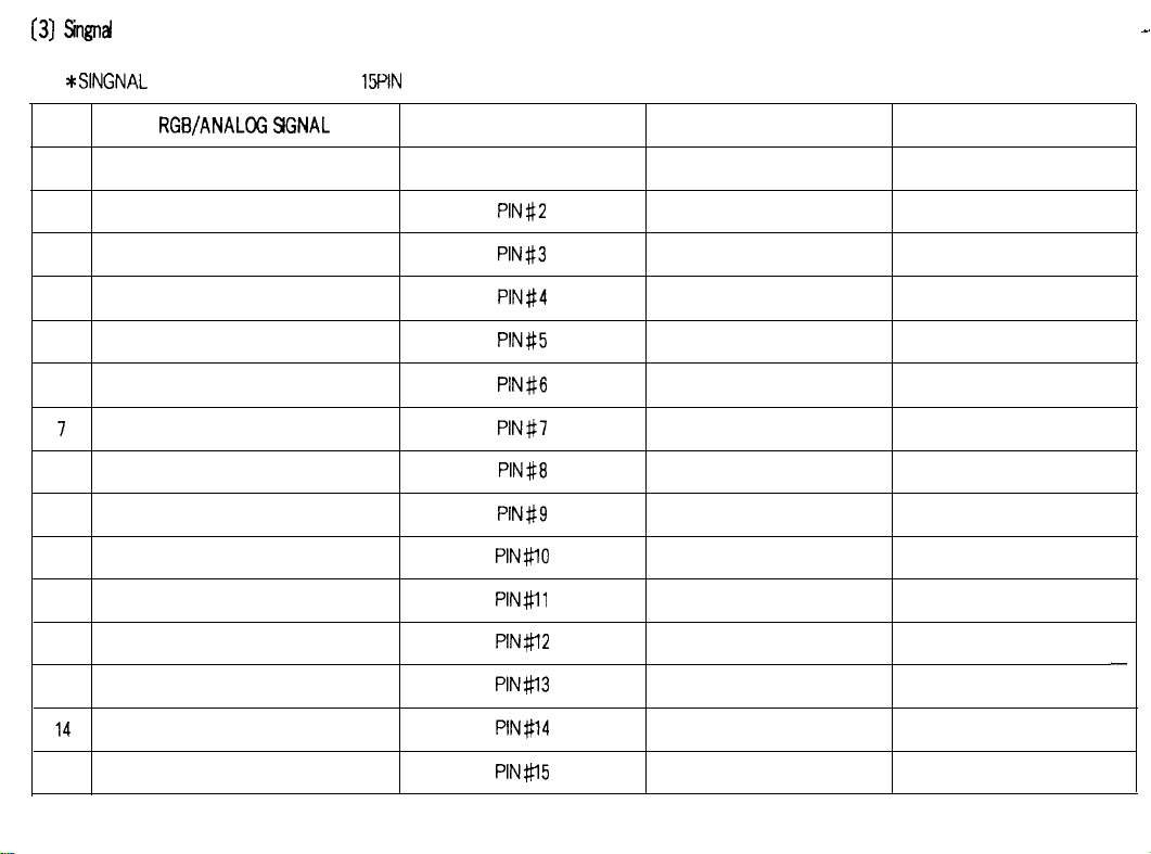
1’31
singnd
cable
pin
connection
-.
* SINGNAL
NO
1
2
3
4
5
6
7
8
9
10
11
12 N.C
13
CABLE PIN CONNECTION (
RGEVANALOGQGNAL
RED PIN # 1 RED
GREEN
BLUE
RESERVED
LOG GROUND
RED GROUND
GREEN GROUND
BLUE GROUND
N.C
SYNCGROUND
GROUND
H-SYNC
15PlN
D-SUB SIGNAL CONNECTOR WITH CABLE)
Fin No.
PIN#2
PIN#3
PIN#4 BLACK
PIN#5 BLACK
PIN#6
PIN#7
PIN#6
PIN#9
PIN#lO BLACK
PIN#ll
PIN#l2
PIN#l3
WIRECOLOR
GREEN
BLUE
SHIELD
SHIELD
SHIELD
BLACK
WHITE
REMARKS
_
-
V-SYNC
14
15 N.C
PIN#14
PINtf15
YELLOW
 Loading...