

Samsung ASA24C6ME, SC24AC6, ASA18C9ME, SC18AC9, OUTDOOR Service Manual
...
ROOM AIR CONDITIONER
INDOOR
ASA24C5(6)ME
SC24AC5(6)
ASA18C9(0)ME
SC18AC9(0)
SERVICE
OUTDOOR
USA24C5(6)ME
SC24AC5(6)X
USA18C9(0)ME
SC18AC9(0)X
Manual
CONTENTSAIR CONDITIONER
1. Precautions
2. Product Specifications
3. Operating Instructions and
Installation
4. Disassembly and Reassembly
5. Troubleshooting
6. Exploded Views and Parts List
7. Block Diagrams
8. PCB Diagrams
9. Wiring Diagrams
10. Schematic Diagrams
1. Precautions
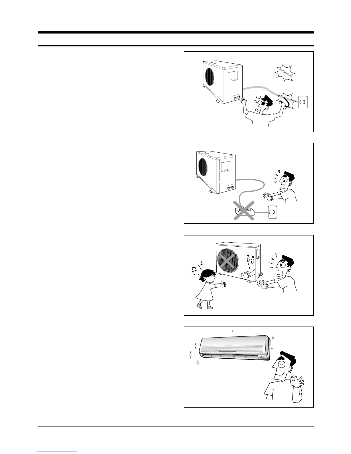
1. Warning: Prior to repair, disconnect the
power cord from the circuit breaker.
2. Use proper parts: Use only exact replacement parts. (Also, we recommend replacing
parts rather than repairing them.)
3. Use the proper tools: Use the proper tools
and test equipment, and know how to use
them. Using defective tools or test equipment may cause problems later-intermittent
contact, for example.
4. Power Cord: Prior to repair, check the
power cord and replace it if necessary.
5. Avoid using an extension cord, and avoid
tapping into a power cord. This practice
may result in malfunction or fire.
6. After completing repairs and reassembly,
check the insulation resistance.
Procedure: Prior to applying power, measure the resistance between the power cord
and the ground terminal. The resistance
must be greater than 30 megohms.
Fig. 1-1 Avoid Dangerous Contact
Fig. 1-2 No Tapping and No Extension Cords
7. Make sure that the grounds are adequate.
8. Make sure that the installation conditions
are satisfactory.
Relocate the unit if necessary.
9. Keep children away from the unit while it is
being repaired.
10. Be sure to clean the unit and its surrounding area.
Fig. 1-3 No Kids Nearby!
O.K
Fig. 1-4 Clean the Unit
1-1Samsung Electronics

MEMO
Samsung Electronics1-2
2. Product Specifications
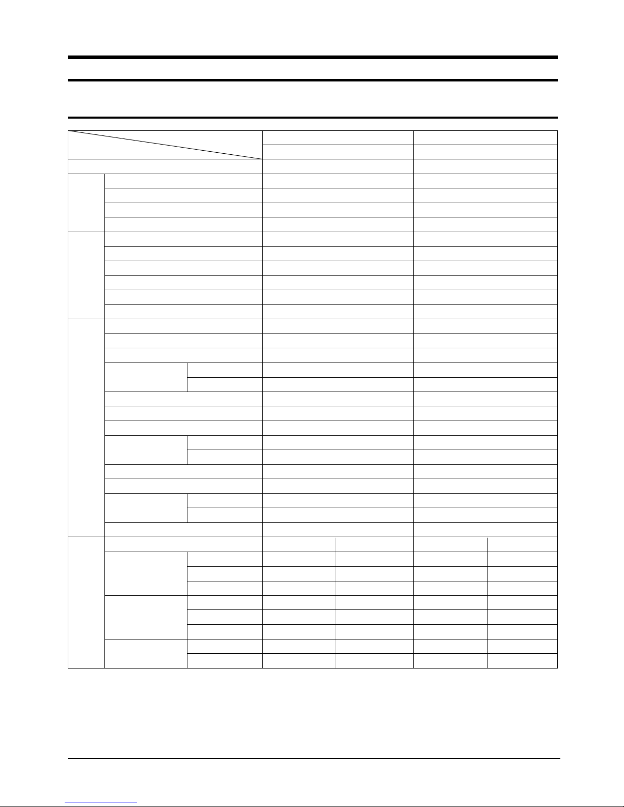
2-1 Table
Item
Power Sourse
Performance
Electrical
Rating
Features
Dimensions
&
Weight
Model
Capacity KW
Air circulation (High) m3/min
Moisture removal (High) Liters/h
Available voltage range V
Running amperes A
Power input kw
Power factor %
Energy efficiency ratio BTU/wh
Compressor locked rotor amperes A
Controls/Temperature control
Control unit
Timer
Fan speed Indoor/Outdoor
Air flow direction (indoor) Horizontal
Vertical
Comperssor
Refrigerant/Amount charged at rating g
Refrigerant control
(Sound pressure) Indoor Hi/Mi/Lo dB-A
Outdoor-Hi dB-A
Refrigerant tubing connections
Max. allowable tubing length at shippint m
Refrigerant tube diameter Narrow tube (in.)
Wide tube (in.)
Refrigerant tube kit/Accessories
Unit dimensions Height mm
Width mm
Depth mm
Package dimensions Height mm
Width mm
Depth mm
Weight Net kg
Shipping kg
ASA24C5(6)ME / SC24AC5(6)
Cooling only
220-240V, 50Hz
6.90(23,500)
14.0
3.2
198 ~ 264
11.6
2.50
95.0
9.4
59
Microprocessor / I.C Thermistor
Wireless remote control
Q-Timer / 24-Hour ON or OFF
3 Steps and Turbo / 2 Step
Manual
Auto
Rotary (Toshiba)
R410A / 1,550g
Capillary tube
49 / 47 / 45
61
Flare type
20
6.35(1/4")
15.88(5/8")
Optional / Hanger-plate
Indoor unit Outdoor Indoor unit Outdoor
275
1080
204
372
1153
272
13
16
638
880
310
719
1023
413
60
64
ASA18C9(0)ME / SC18AC9(0)
Cooling only
220-240V, 50Hz
5.30(18,000)
13.0
2.2
198 ~ 264
7.9
1.83
95.0
9.8
52
Microprocessor / I.C Thermistor
Wireless remote control
Q-Timer / 24-Hour ON or OFF
3 Steps and Turbo / 1 Step
Manual
Auto
Rotary (Toshiba)
R410A / 1,300g
Capillary tube
46 / 44 / 42
58
Flare type
15
6.35(1/4")
12.7(1/2")
Optional / Hanger-plate
275
1080
204
372
1153
272
13
16
620
787
320
692
909
444
52.5
56.0
Remarks : Rating Conditions are :
Indoor air temperature : 27.0˚C DB/19.0˚C WB
Outdoor air temperature : 35.0˚C DB/24.0˚C WB
2-1Samsung Electronics
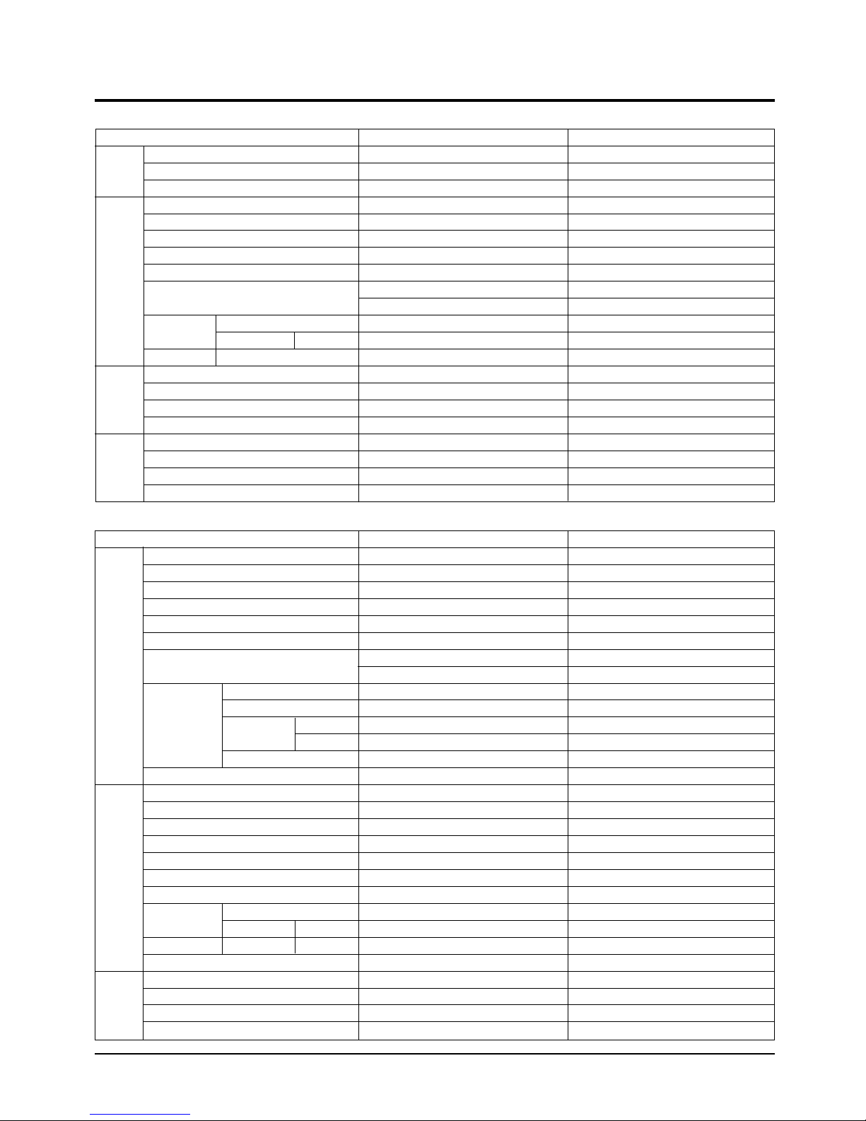
2-2 Major Component specifications
■
Indoor unit
Model
Part No.
PCB
Controls
Control circuit fuse
Type
Dia. and length mm
Fan motor model
Pols,rpm(at 240V)
Fan
Normal out W
&
Fan Motor
S-Motor
Exch.
■
Compressor
Fan Motor
Coil resistance(Ambient temp.20˚C) Ω
Safety devices Type
Operating temp. Open ˚C
Run capacitor µF x VAC
Type
Model
Rating
Coil resistance (Ambient temp. 25˚C) Ω
Coil
Rows x Steps
Heat
Fin pitch mm
Face area m
Outdoor unit
Model
Type
Compressor model
Normal output W
Comperssor oil kind
Comperssor oil cc
Oil Specific gravity
Coil resistance(Ambient temp.25˚C) Ω
Safety devices Type
Overloal relay
Operating temp. Open ˚C
Operating amp(Ambient temp.)
Run capacitor µF x VAC
Type
Dia. and length mm
Fan motor model
Pols, rpm(at240V)
Fan
Normal output W
&
Coil resistance(Ambient temp.20˚C) Ω
Safety devices Type
Operating temp. Open ˚C
Run capacitor µF x VAC
Coil
Rows x Steps
Heat
Exch.
Fin pitch mm
Face area m
2
Close ˚C
Close ˚C
2
ASA24C5(6)ME / SC24AC5(6)
PD-SH30ZC-01
Microprocessor
250V, 3.15A
Cross-Flow
ø95/L = 842
IC-9430SKJ5A
4P, 1350 RPM
40W
MAIN : 160Ω
SUB : 227Ω
17AM034A5
135 ± 5°C
2.0µF X 450VAC
MSFCC20A03
DC 12V
530Ω
AL-FIN/Copper tube
2 x 15
1.2
0.265
USA24C5(6)ME / SC24C5(6)X
ROTARY
PA290X3F-4MS(E)
2570
RB68AF (P.O.E)
1400
-
Start winding : 2.20
Run winding : 1.07
UP2TF7225-141
Internal Line Break
165
95
73.0 AT 2-10 SECOND
45µF X 450VAC
Propeller
ø460
OSME-906SRC
6P, 850 RPM
70W
-
-
17AM034A5
135±5°C
4µF x 450VAC
AL-FIN / Copper tube
2 x 28
1.5
0.538
ASA18C9(0)ME / SC18AC9(0)
PE-S1452R-00
Microprocessor
250V, 3.15A
Cross-Flow
ø95/L = 842
IC-9430SKJ5A
4P, 1350 RPM
40W
MAIN : 160Ω
SUB : 227Ω
17AM034A5
135 ± 5°C
2.0µF X 450VAC
MSFCC20A03
DC 12V
530Ω
AL-FIN/Copper tube
2 x 15
1.5
0.265
USA18C9(0)ME / SC18AC9(0)X
ROTARY
PA225X3F-4MSE
1950
RB68AF (P.O.E)
1200
-
Start winding : 2.68
Run winding : 1.35
UP3SE0391-T39
Internal Line Break
160
90
26.8A / 6~16 SECOND
45µF X 450VAC
Propeller
ø405
AMASS030AVEB
4P, 1050RPM
35W
-
-
17AM037A5
150±5°C
2.5µF x 450VAC
AL-FIN / Copper tube
2 x 28
1.5
0.500
Samsung Electronics2-2
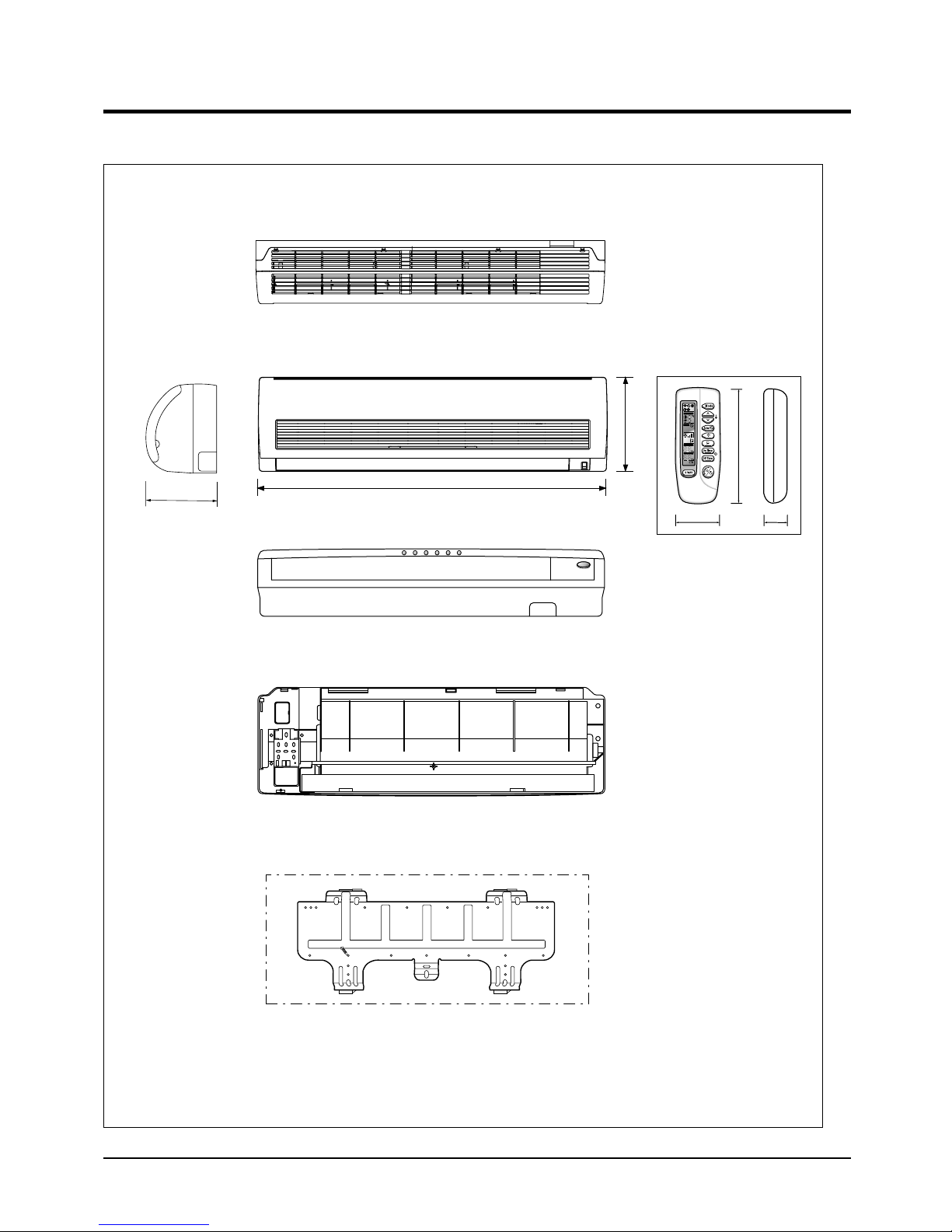
2-3 Dimensions
275
1080
2-3-1 Indoor Unit
204
(Front view)
(Rear view)
(Remote control)
115
2245
✳The feature is subject to be varied as a model.
Installation plate
2-3Samsung Electronics
Product Specifications
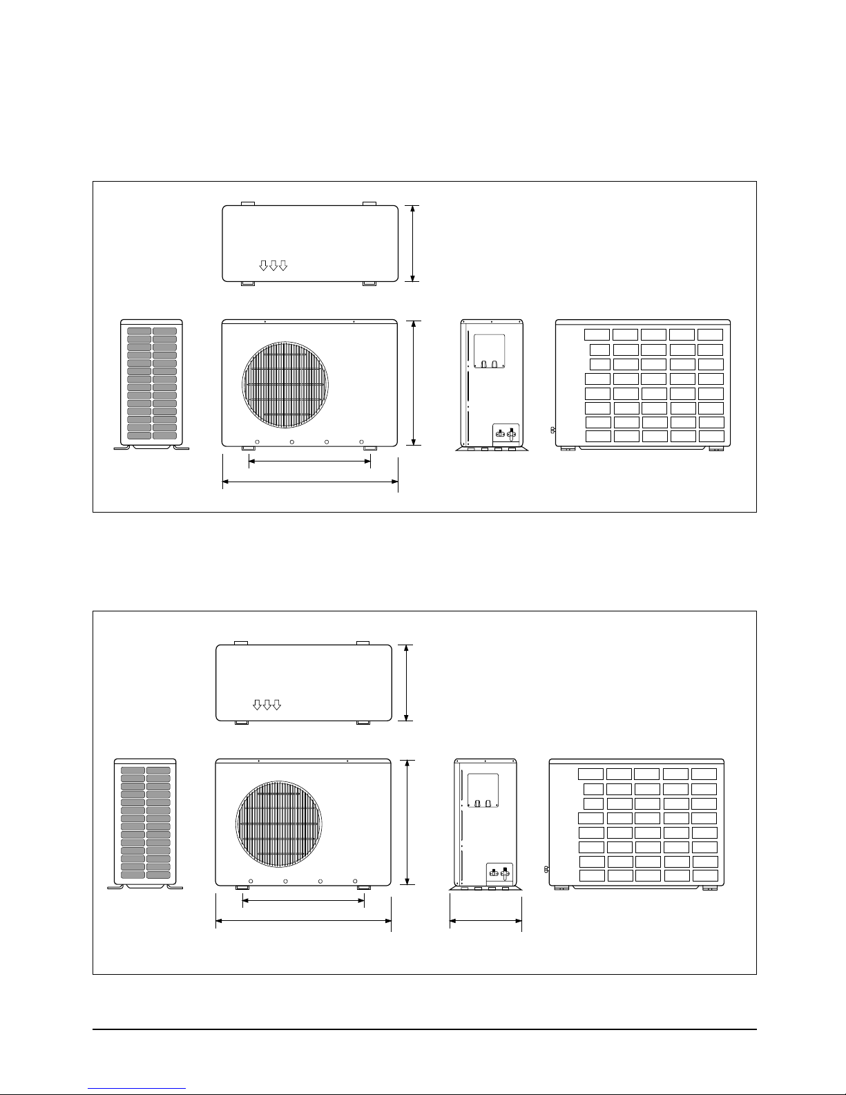
2-3-2 Outdoor Unit
■ 24K BTU
310
(Front view) (Rear view)
638
660
880
■ 18K BTU
320
(Front view) (Rear view)
620
582
787
340
Samsung Electronics2-4
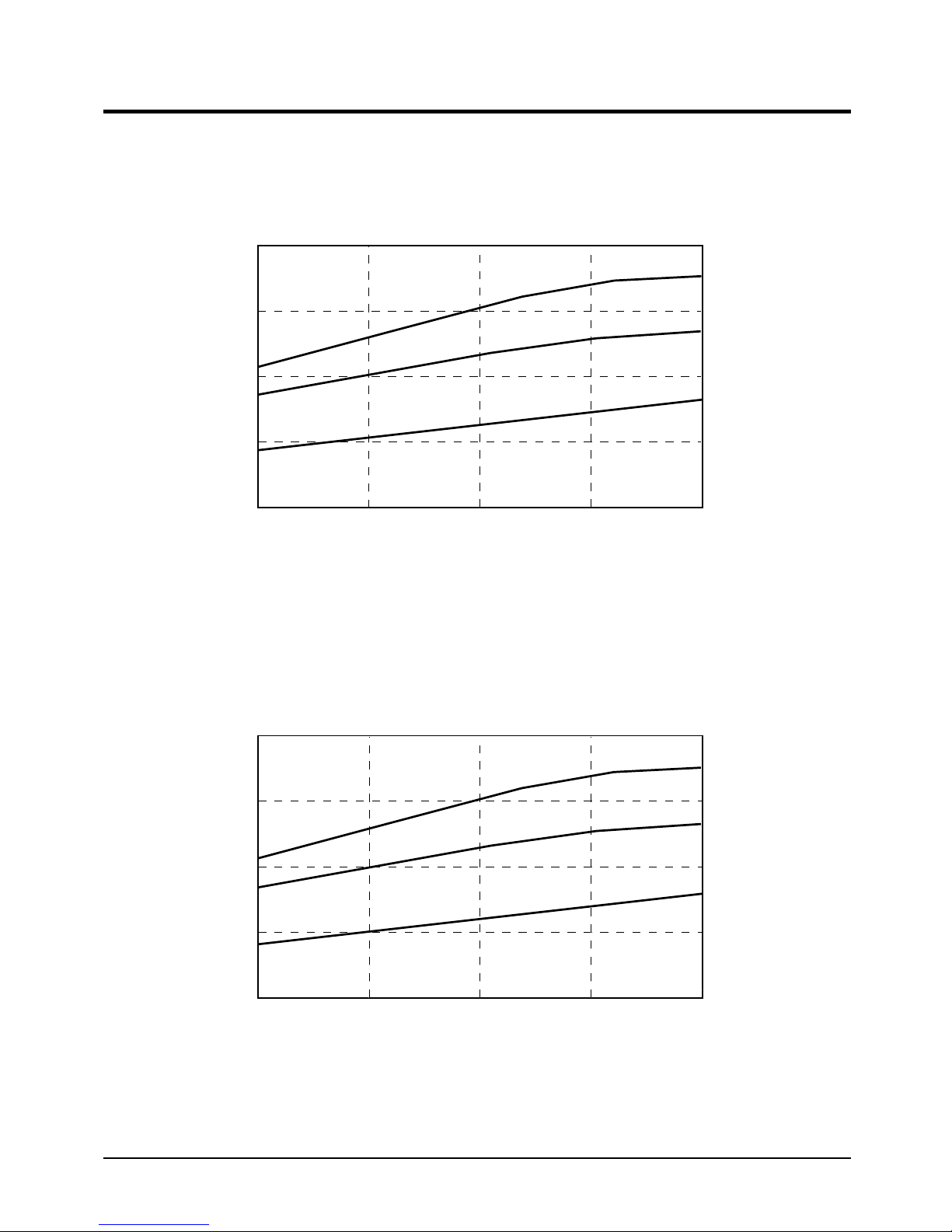
2-4 Pressure Graph
10
9
8
7
6
20 25 30 35
Outdoor drybulb temp [deg C]
Low Pressure [kg/cm
2
G]
40
30.6/22.5
27/19
21.5/14.6
10
9
8
7
6
20 25 30 35
Outdoor drybulb temp [deg C]
Low Pressure [kg/cm
2
G]
40
30.6/22.5
27/19
21.5/14.6
■ 24K BTU
■ 18 BTU
2-5Samsung Electronics

MEMO
Samsung Electronics2-6
3. Operating Instructions and Installation
3-1 Operating Instructions
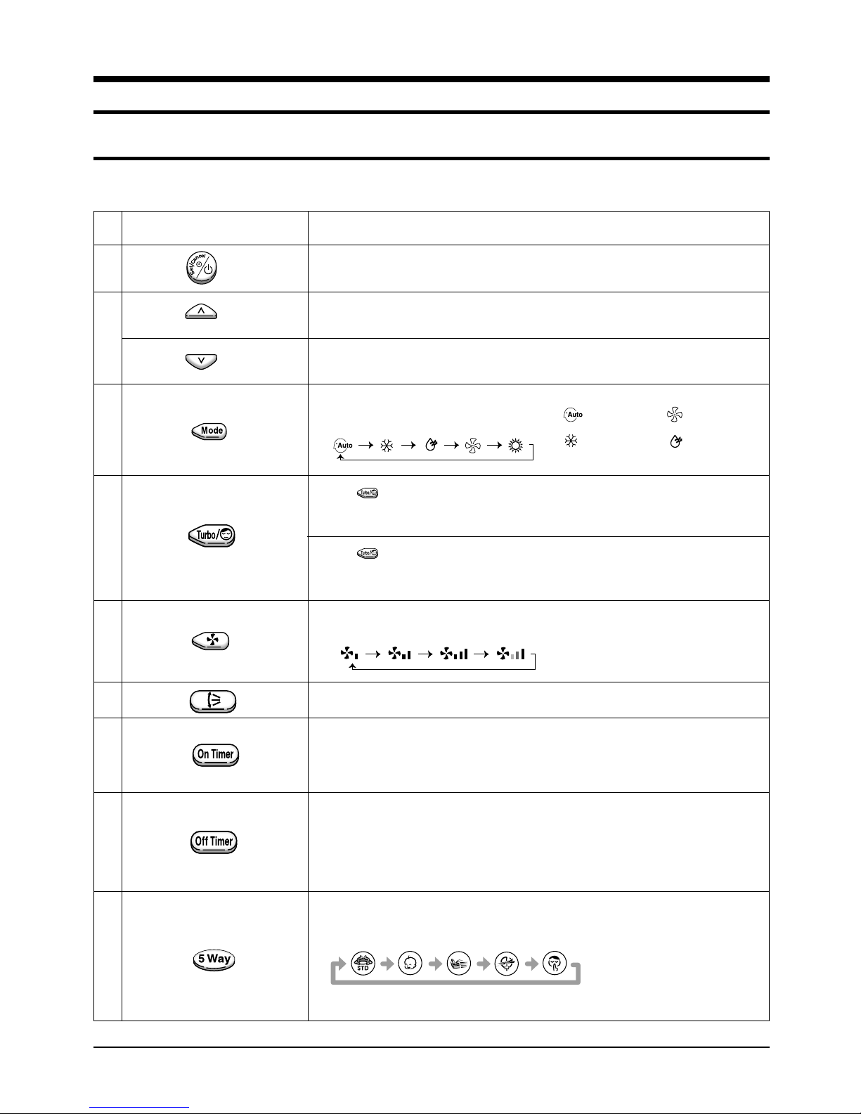
3-1-1 The Feature of Key in remote controller
NO
NAMED OF KEY
1
(UP)
2
(DOWN)
3
4
5
Power On/Off button to start and stop airconditioner or timer set up
Temp. up button. To increase the temperatute by the pressing
the temperature button
Temp. down button. To decrease the temperature by the pressing
the temperature button
Each time you press this button
Mode is changed in the following order
Press until the appearance. the air condition cools or heats
the room as quickly as possible. after 30minutes, the air,
the airconditioner is reset automatically to the previous mode
Press until the appearance. the sleep timer can be used when
you are cooling your room to switch the air conditioner off
automatically after a perriod of six hours.
Each time you press this button,
FAN SPEED is changed in the following order.
FUNCTION OF KEY
: Auto Mode : Fan Only
: Cool Mode : Dry Mode
6
7
8
9
Adjust air flow vertically.
The ON Timer enables you to switch onthe air conditioner automatically
after a given period of time that is from 30 minutes to 24 hours.
To cancel the On Time, press the (Set/Cancel) button.
The Off Timer enables you to switch off the air conditioner automatically
after a given period of time that is from 30 minutes to 24 hours.
To cancel the On Time, press the (Set/Cancel) button.
To select the 5 way function with the remote control, press the 5 way
button one or more times until the desired mode is selected.
Each time you press the 5 way button
Each 5 way indicator on the indoor unit comes on in or der.
3-1Samsung Electronics
Operating Instructions and Installation
3-1-2 Name & Function of Key in remote controller
1. AUTO MODE : In this mode, operation
mode(COOL) is selected automatically by
the room temperature of initial operation.
Operation Type
Cool Operation
∆T= -1°C, -2°C, 0°C+1°C+2°C
∆T is controlled by setting temperature
up/down key of remote controller.
*FAN SPEED : AUTO
2. COOL MODE : The unit operates according
to the difference between the setting and
room temperature. (18°C~30°C)
3. DRY MODE : Has 3 states, each determined
by room temperature.
The unit operates in DRY mode.
*Compressor ON/OFF Time is controlled
compulsorily(can not set up the fan speed,
always breeze).
*Protective function : Low temperature
release. (Prevention against freeze)
4. TURBO MODE : This mode is available in
AUTO, COOL, DRY, FAN MODE.
When this button is pressed at first, the air
conditioner is operated “powerful” state for
30 minutes regardless of the set temperature, room temperature.
When this button is pressed again, or when
the operating time is 30 minutes, turbo
operation mode is canceled and returned to
the previous mode.
*But, if you press the TURBO button in DRY
or FAN mode that is changed with AUTO
mode automatically.
Tr≥25˚C+∆T Compressor ON
Tr≤24˚C+∆T Compressor OFF
Room Temp.
*In COOL mode : The setting temperature
is automatically raised by 1°C each 1hour
When the temperature has been raised by
total of 2°C, that temperature is maintained.
6. FAN SPEED : Manual (3 step), Auto (4 step)
Fan speed automatically varies depending
on both the difference between setting and
the room temperature.
7. COMPULSORY OPERATION :
For operating the air conditioner without
the remote controller.
*AUTO : The operating is the same function that AUTO MODE in the remote controller. And each time you press the button
the 5WAY function is changed as follow.
STD ➝ NATURE ➝ POWER ➝ SAVING ➝
SILENCE ➝ POWER OFF
Each time you press This button, 5WAY
function is changed in the following order
STD(standard) ➝ NATURE ➝
POWER(High-speed) ➝ Saving(PowerSaving) ➝ SILENCE ➝ POWER OFF
❊ STD(standard)( ) : General operation
Mode
❊ NATURE( ) : The unit is operated
according to health
pattern control
❊ POWER( ) : The unit is operated in
powerful state
❊ SAVING( ) : The unit is operated in
power saving state
❊ SILENCE( ) : The unit is operated
quitely
Each mode has Auto, Cool and SLEEP
operation designed in advance.
5. SLEEP MODE : Sleep mode is available
only in COOL or mode.
The operation will stop after 6 hours.
Samsung Electronics3-2

8. SWING : BLADE-H is rotated vertically by
the stepping motor.
*Swing Set : Press the button under the
remote control is displayed on LCD the
and the blades move up and down. If the one
more time press the button, blades location is stop.
9. 24-Hour ON/OFF Real Setting Timer. : The
air conditioner is turned ON at a specified
time using .
OFF TIMER : The air Conditioner is turned
OFF at a specified time using .
*ON TIMER : Only timer LED lights on.
*OFF TIMER : Both timer and operation
LED lights on.
Operating Instructions and Installation
10. SELF Diagnosis
LED DISPLAY
TIMER
STD
Check Point
Indoor unit room temperature sensor
error(open or short)
Indoor unit heat exchanger temperature
sensor error(open or short)
Indoor fan mal function
EEPROM error
Option error(option wasn’t set up or
option data error)
LED
:
blinking
: LED off
NATURE POWER SAVING SILENCE
11. BUZZER SOUND : Whenever the ON/OFF
button is pressed or whenever change
occurs to the condition which is set up or
select, the compulsory operation mode,
buzzer is sounded "beep".
3-3Samsung Electronics
3-2 Installation
3-2-1 Selecting Area for Installation
Select an area for installation that is suitable
to the customer's needs.
3-2-1(a) Indoor Unit
1. Make sure that you install the indoor unit in
an area providing good ventilation. It must
not be blocked by an obstacle affecting the
airflow near the air inlet and the air outlet.
2. Make sure that you install the indoor unit in
an area allowing good air handling and
endurance of vibration of the indoor unit.
3. Make sure that you install the indoor unit in
an area where there is no source of heat or
vapor nearby.
4. Make sure that you install the indoor unit in
an area from which hot or cool air is spread
evenly in a room.
5. Make sure that you install the indoor unit in
an area away from TVs, audio units, cordless phones, fluorescent lighting fixtures
and other electrical appliances (at least 1
meter).
6. Make sure that you install the indoor unit in
an area which provides easy pipe connection with the outdoor unit, and easy
drainage for condensed water.
7. Make sure that you install the indoor unit in
an area which is large enough to accomodate the measurements shown in figure on
the next page.
3-2-1(b) Outdoor Unit
1. Make sure that you install the outdoor unit
in area not exposed to the rain or direct sun
light.
(Install a separate sunblind if exposed to
direct sun light.)
2. Make sure that you install the outdoor unit
in area allowing good air moment, not
amplifying noise or vibration, especially to
avoid disturbing neighbours.
(Fix the unit firmly if it is mounted in a
high place.)
3. Make sure that you install the outdoor unit
in area providing good ventilation and
which is not dusty. It must not be blocked
by any obstacle affecting the airflow near
the air inlet and the air outlet.
4. Make sure that you install the outdoor unit
in area free from animals or plants.
5. Make sure that you install the outdoor unit
in area not blocking the traffic.
6. Make sure that you install the outdoor unit
in area easy to drain condensed water from
the indoor unit.
Make sure that you install the outdoor unit in
7.
area which provides easy connection
within the maximum allowable length of a
coolant pipe(18✳✳:15meters, 24✳✳:20meters).
Note
1. Add (18✳✳:30g, 24✳✳:40g) of refrigerant (R410A)
for every 1 meter if the pipe length exceeds the
standard pipe length of 5 meters.
2. Maintain a height between the indoor and outdoor
units of less than 8 meters.
8. Make sure that you install the outdoor unit
in an area which is large enough to accommodate the measurements
3-2-1(c) Remote Control Unit
1. Make sure that you install the remote control unit in an area free from obstacles such
as curtains etc, which may block signals
from the remote control unit.
2. Make sure that you install the remote control unit in an area not exposed to
direct sunlight, and where there is no source
of heat.
3. Make sure that you install the remote control unit in an area away from TVs, audio
units, cordless phones, fluorescent lighting
fixtures and other electrical appliances (at
least 1 meter).
Caution :
It is harmful to the air conditioner if it is used in the following environments: greasy areas (including areas near machines),
salty areas such as coast areas, areas where sulfuric gas is present such as hot spring areas. Contact your dealer for advice.
Samsung Electronics3-4
Cut the piping hole
sloped slightly
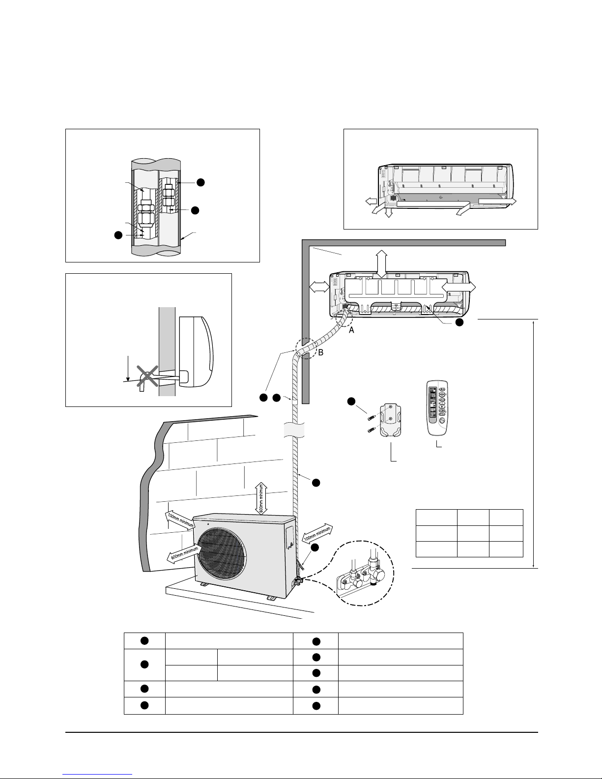
3-2-2 Installation diagram of indoor unit and outdoor unit
Operating Instructions and Installation
A Indoor unit gas leak test check point
Indoor unit
Piping
2
3
1
Tape vinyl
B Drain hose installation
Cut the piping hole
sloped slightly
Piping may be laid to the rear, left,
right or down .
Right
Rear
Down
70mm or more
250mm
or more
5
6
8
Rear
200mm or more
7
“H”metere
s maximum
Left
Remote control
Remote control holder
4
Model L H
**18**
9
1
2
3
4
Piping (Liquid) 1/4" Putty
18K BTU Piping(Gas) 1/2”
24K BTU Piping(Gas) 5/8”
Installation tube Screw
Vinyl tape Drain hose
5
6
7
8
9
Clamper tube
Installation plate
**24**
15 8
20 8
3-5Samsung Electronics
Operating Instructions and Installation
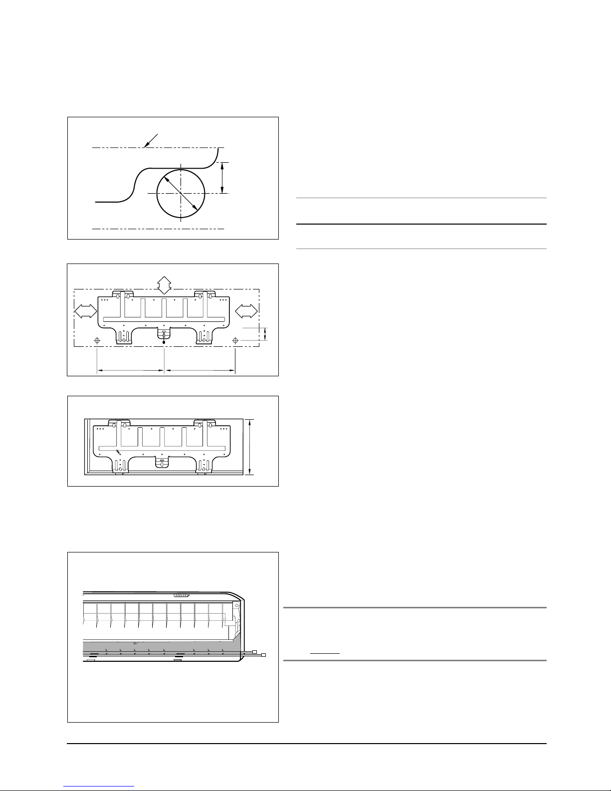
3-2-2(a) Fixing the Installation Plate
(Unit : mm)
(Unit : mm)
Installation plate
512
1. Determine the position of the pipe and drain hose hole
using the right figure and drill the hole with an inner
diameter of 65mm so that it slants slightly downwards.
Pipe hole
(ø65mm)
2. If you are fixing the indoor unit to a… Then follow Steps…
Wall 3.
Window frame 4 to 6.
3. Fix the installation plate to the wall in a manner appro-
60
325255
priate to the weight of the indoor unit.
If you are mounting the plate on a concrete wall with
anchor bolts, the anchor bolts must not project by more
than 20mm.
45
415
4. Determine the positions of the wooden uprights to be
attached to the window frame.
5. Attach the wooden uprights to the window frame in a
manner appropriate to the weight of the indoor unit.
410~730
6. Using tapped screws, attach the installation plate to the
wooden uprights, as illustrated in the last figure opposite.
3-2-2(b) Purging the Unit
On delivery, the indoor unit is loaded with an inert gas.
All this gas must therefore be purged before connecting the
assembly piping. To purge the inert gas, proceed as follows.
Unscrew the caps at the end of each pipe.
Result : All inert gas escapes from the indoor unit.
• To prevent dirt or foreign objects from getting into
the pipes during installation, do NOT remove the
caps completely until you are ready to connect the
piping.
Samsung Electronics3-6
Operating Instructions and Installation
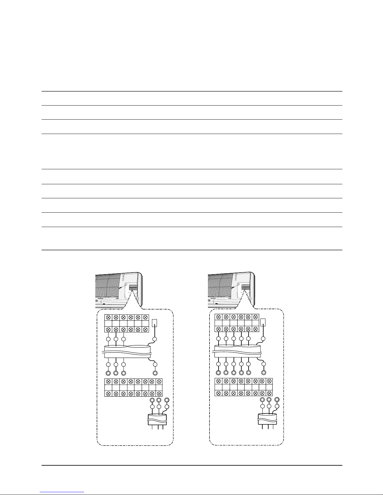
N1 L1 1 2 34NL
N1 L1 1 2 34
1
L1
N1
E1
L1
N1
E
E
N
L
E
Indoor
unit
Outdoor unit
Circuit Breaker
(Main Power)
N1 L1 1 2 34NL
N1 L1 1 2 34
Indoor
unit
Outdoor
unit
Circuit Breaker
(Main Power)
3
2
1
L1
N1
E
3
2
1
L1
N1
E
E
N
L
E
3-2-2(c) Connecting the Assembly Cable.
The indoor unit is powered from the outdoor unit via the assembly cable. If the outdoor unit is more than
five metres away from the indoor unit, the cable must first be extended to a maximum of 15 metres.
1. Extend the assembly cable if necessary.
2. Open the front grille by pulling on the tabs on the lower right and left sides of the indoor unit.
3. Remove the screw securing the connector cover.
4. Pass the assembly cable through the rear of the indoor unit and connect the assembly cable to terminals
N1, L1, 1, 2, 3.
• Each wire is labelled with the corresponding terminal number.
5. Firmly fix the ass’y cable with clamp wire holder.
6. Pass the other end of the cable through the 65mm hole in the wall.
7. Replace the connector cover, carefully tightening the screw.
8. Close the front grille.
9. For further details on how to plug the other end of the assembly cable into the outdoor unit, refer to
page 3-8.
<✳✳18✳✳>
<✳✳24✳✳>
3-7Samsung Electronics
Operating Instructions and Installation
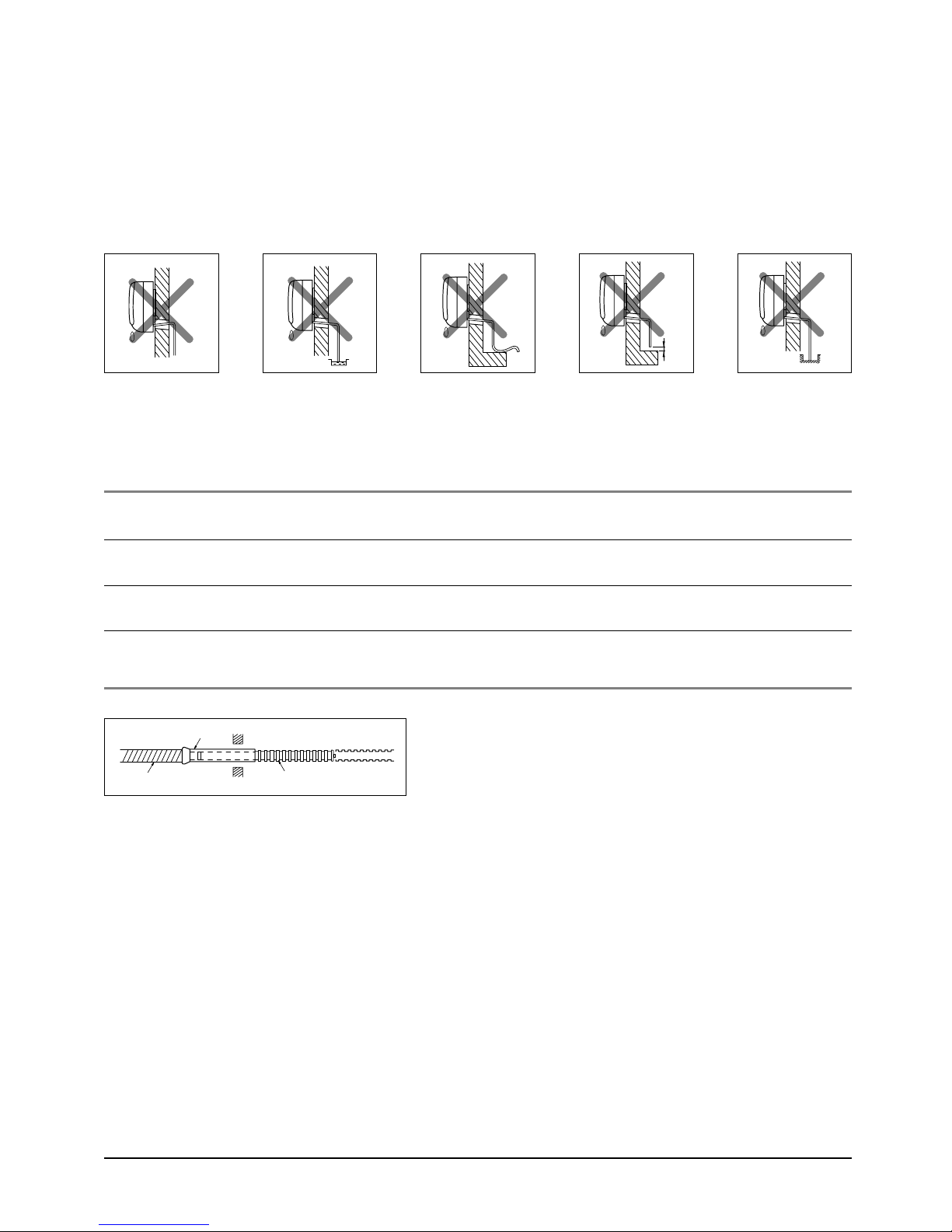
3-2-2(d) Installing and Connecting the Indoor Unit Drain Hose
Care must be taken when installing the drain hose for the indoor unit to ensure that any condensation water is correctly drained outside. When passing the drain hose through the 65mm hole drilled in
the wall, check that none of the following situations occur.
5cm
less
The hose must
NOT slope upw
ards.
To install the drain hose, proceed as follows.
1. If necessary, connect the 2-metre extension to the drain hose.
The end of the drain
hose must NOT be
placed in water.
Do NOT bend the
hose in different
directions.
Keep a clearance of at
least 5cm between the
end of the hose and the
ground.
Do NOT place the end
of the drain hose in a
hollow.
2. If you are using the extension, insulate the inside part of the extension drain hose with a shield.
3. Pass the drain hose under the refrigerant piping, taking care to keep the drain hose tight.
4. Pass the drain hose through the hole in the wall, making sure that it is sloping downwards, as
shown in the illustrations above.
Shield
Drain hose Extension drain hose
Samsung Electronics3-8
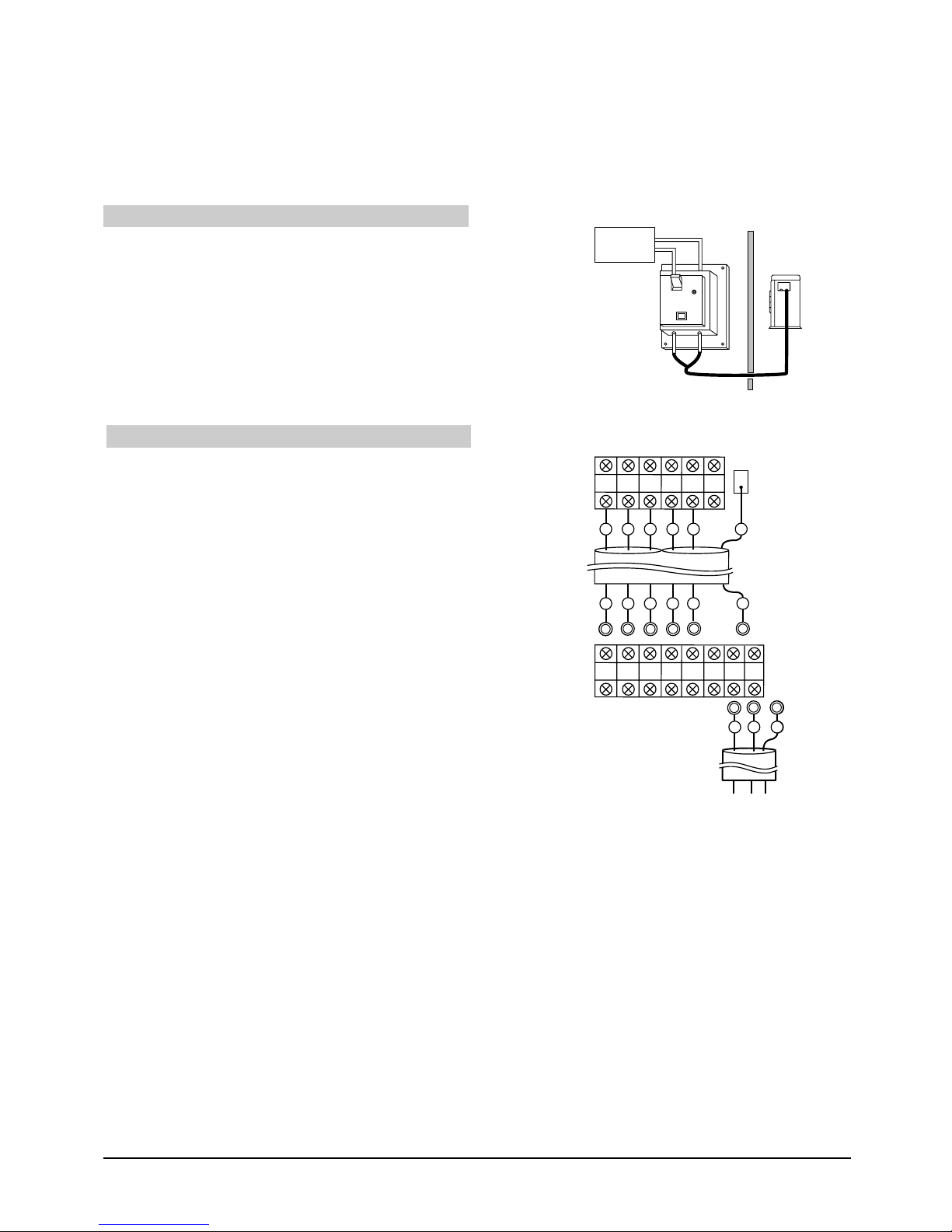
3-2-2(e) Outdoor unit installation
N1 L1 1 2 34NL
N1 L1 1 2 34
3
2
1
L1
N1
E
3
2
1
L1
N1
E
E
N
L
E
AUXILIARY POWER S/W
Auxiliary power S/W should be installed near indoor
unit so that each access is possible.Main/Outdoor unit
power cords are connected to upper/lower terminal of
auxiliary power S/W.
WIRING CONNECTION
Indoor unit connector wire should be connected to
both indoor unit connector and outdoor unit terminal
board as shown in the figure below.
Distributind
board
Auxiliary
power S/W
Operating Instructions and Installation
ON
OFF
Indoor unit
Outdoor unit
Circuit Breaker
(Main Power)
3-9Samsung Electronics
Operating Instructions and Installation
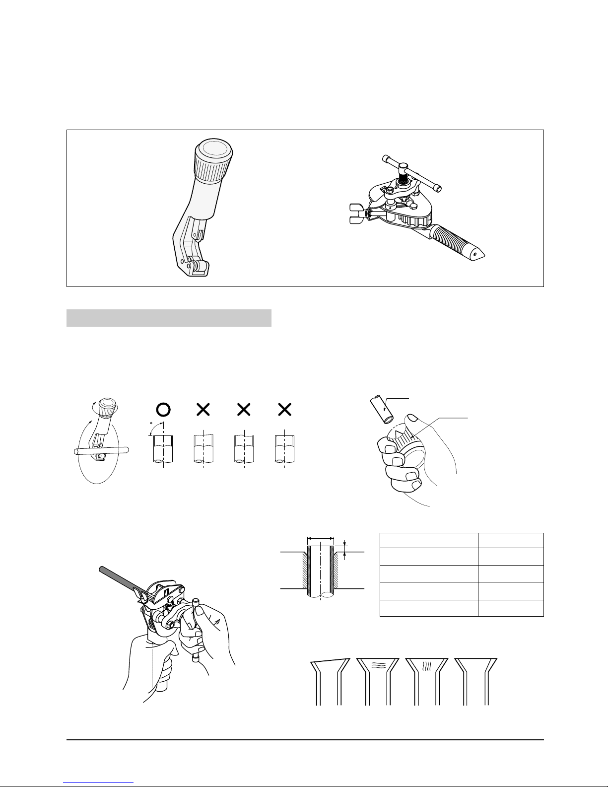
3-2-2(f) Flare Modification
• Tools used
Flare modification procedure
1) Cut the pipe using a pipe cutter.
90
Oblique Raughness Burr
3) Insert a flare nut into the pipe and
modify flare.
2) Remove burrs at the tip of the pipe cut.
Caution : Burrs not removed may result in
leakage of gas.
Pipe
Reamer
D
D
A
A
Outer diameter A(mm)
ø6.35mm 1.3
ø9.52mm 1.8
ø12.7mm 2.0
ø15.8mm 2.2
* Unproper flaring
Inclined Surface
damaged
Cracked Uneven
thickness
Samsung Electronics3-10
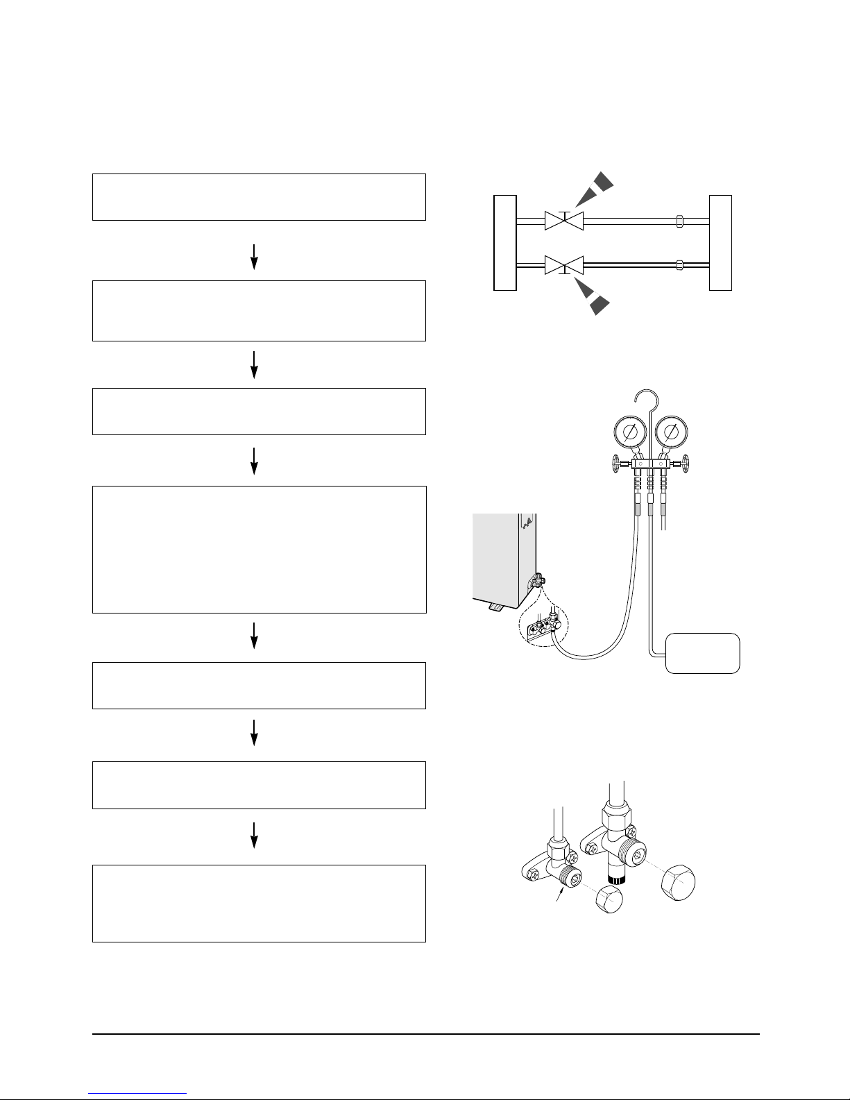
3-2-2(g) Air-Purge Procedureand pipe.
Operating Instructions and Installation
1. Connect each assembly pipe to the appropriate valve on the
outdoor unit and tighten the flare nut.
2 Connect the charging hose of low pressure side of manifold
gauge to the packed valve having a service port (1/2” or
5/8” Packed valve) as shown at the figure.
3 Open the valve of the low pressure side of manifold gauge
counter-clockwise.
4. Purge the air from the system using vacuum pump for about
30 minutes.
- After that, please recheck that pressure is staloilization.
- Close the valve of the low pressure side of manifold gauge
clockwise.
- Remove the hose of the low pressure side of manifold
gauge.
Outdoor unit
Indoor unit
A
B
Gas pipe side
Liquid pipe side
C
D
5. Set valve cork of both liquid side and gas side of packed
valve to the open position.
6. Mount the valve stem nuts to the 2-way and 3-way valve.
And mount the service port cap to 3-way valve.
7. Check for gas leakage.
- At this time, especially check for gas leakage from the
3-way valve’s stem nuts, and from the service port cap.
Valve stem
B
(liquid)
A
(gas)
Vacuum Pump
Stem cap
3-11Samsung Electronics
 Loading...