

Page 1

CD-ROM DRIVE
SC-140/148
User's Guide - ENGLISH
When handling the drives, you may hear a slight
rattle inside the unit.
This is NOT a problem, it is simply the ball
bearings of the Auto Balancer shifting.
http://www.samsungelectronics.com
BG68-00044A Rev 02
Page 2

Safety Warnings
1
The following diagrams illustrate the precautions to be taken when using your
CD-ROM drive.
You must not use the drive in any manner other than that specified in this guide.
To reduce the risk of fire or electric shock, do not expose this appliance to rain or
moisture.
CAUTION
Do not attempt to repair the CD-ROM drive yourself. Contact your
dealer or local SAMSUNG representative for all repairs.
Use of controls or adjustments or performance of procedures other
than those specified here in may result in hazardous radiation
exposure
WARRANTY
Please refer to the Samsung limited warranty statements.
Page 3

Front View of the CD-ROM Drive
2
COMPACT
1
1
23456
Headphone Connector
The audio output connector enables you to plug stereo headphones into the drive. It requires a 3.6
mm stereo mini-jack.
6
Stop/Open/Close-Button
When in play, press the stop key and when in stop, press open/close key.
4
Disc Tray
The Disc Tray opens and closes automatically when you press the Open/Close button.
◆
When you place a disc in the tray, make sure that the label on the disc is
facing upwards. If you are not loading or unloading a disc, the disc tray should
remain closed.
5
Emergency Hole
If the disc tray does not open when you press the Open/Close
button, insert a small, metal rod(an unwound paper clip for example) into this
hole to eject the disc.
☛This function should only be performed when the computer is powered OFF.
2
Volume Control Dial
This control dial adjusts the volume for your headphones. You can only use the headphone jack and
volume control when you have installed the required software utilities. For example, the Microsoft
Windows Media player can be used.
3
LED
Page 4
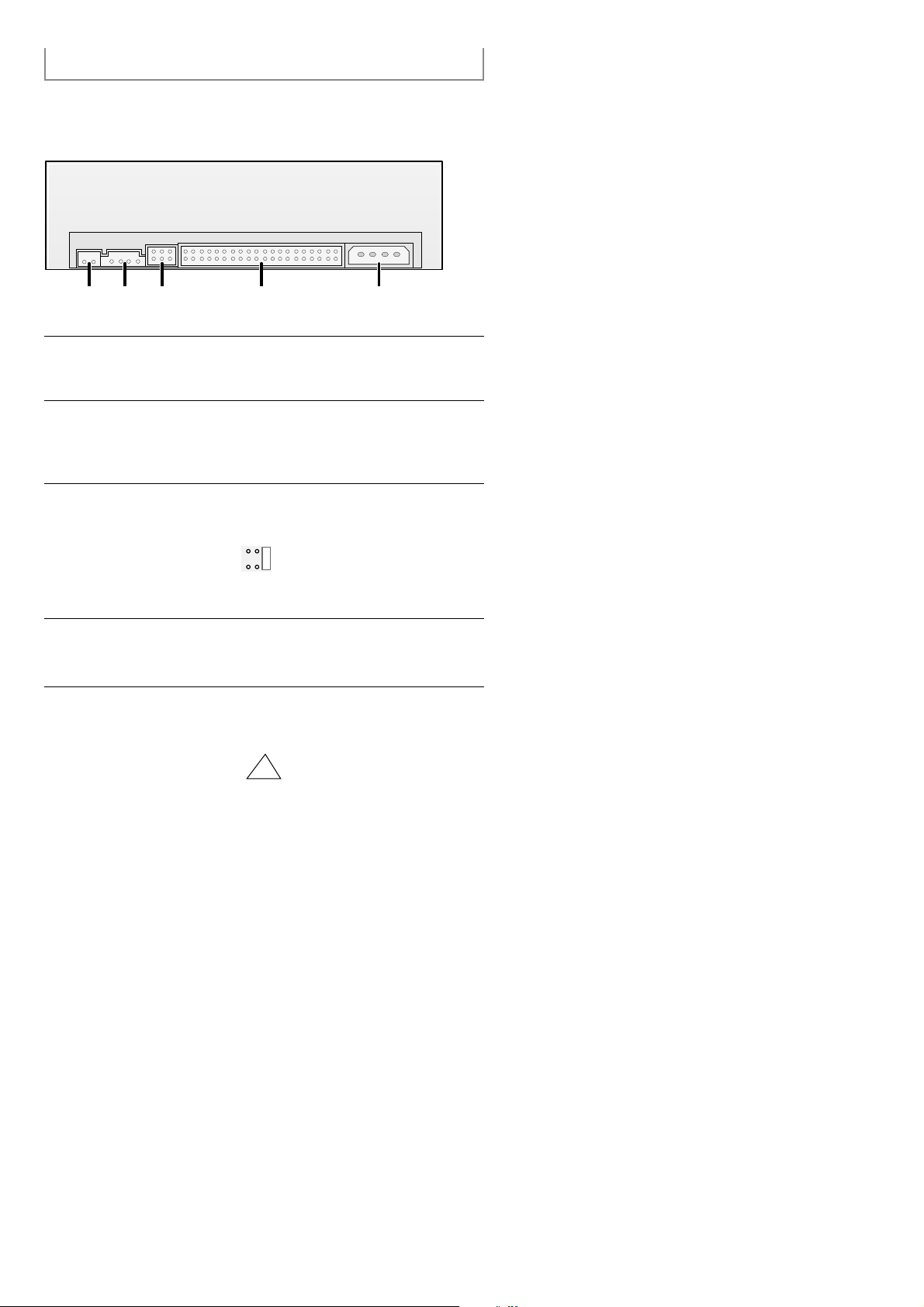
Rear View of the CD-ROM Drive
3
1123 4 5
Digital Audio
You can connect a sound card or MPEG card which support Digital Audio to your drive using this
two-pin connector.
2
Audio Output Connector
You can connect a sound card to your drive using this four-pin connector.
☛ This function is not covered in detail in this guide. Refer to the documentation
supplied with your sound card.
3
Device Configuration Jumper
Usually, this is a pre-set configuration as illustrated below.
☛ Verify that the setting is as illustrated. If it is not, simply remove the jumper
and place it in the correct position.
4
Host IDE Interface connector
This input/output interface connector is used to connect the 40-pin flat cable from the IDE
interface to the CD-ROM drive.
5
Power Connector
The power connector is a four-conductor male plug.
CSSLM
A
Page 5
System Requirements
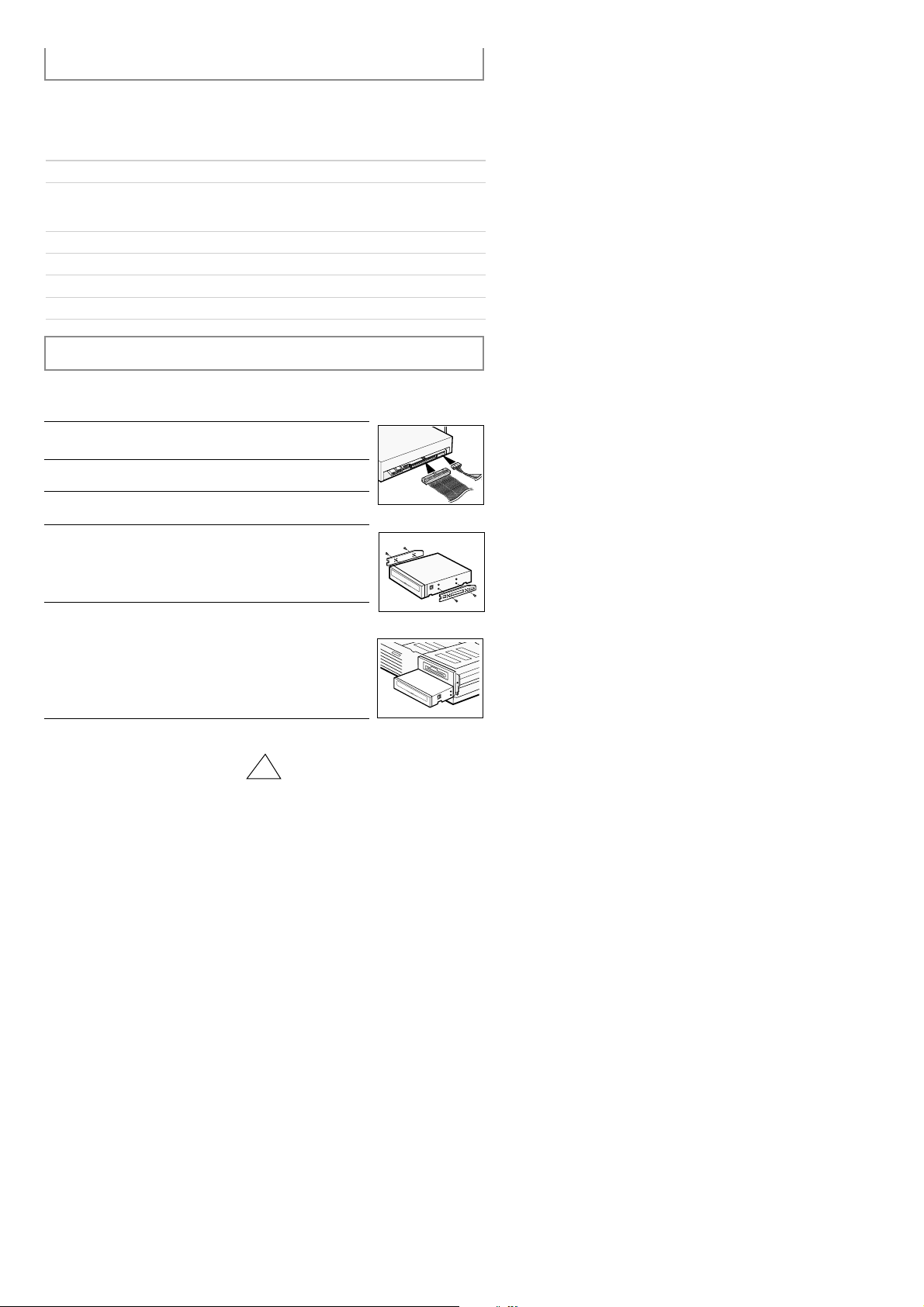
4
1
Turn OFF your computer. Remember to verify the configuration
jumper on the rear of the CD-ROM drive.
2
Remove the cover of your PC(main unit of the computer)
3
Remove the blank cover panel of the 5.25 inch unit in which the
CD-ROM drive is to be installed.
6
Put the cover back on your PC.
5
Install the CD-ROM drive into the unit and secure it with mounting
screws (recommended standard M3x6x4)
☛ ◆ Depending on your PC model, you may need to
attach guide rails to the drive, so that the drive is
held firmly in place.
☛◆ If you use screws that are longer than the
recommended standard, you may damage the
drive.
Before you install the CD-ROM drive, we strongly recommend that you
make certain that your set-up meets the system requirements listed below.
Installing the CD-ROM Drive
Install the CD-ROM drive in your computer horizontally, making sure that the
To install the drive, proceed as follows.
4
Connect the CD-ROM drive to the IDE interface and power cables
Iocated inside your computer.
☛ Connectors are keyed so it is impossible to put them in
an incorrect position. Do not force the connectors, if they
do not seem to fit.
Item
Windows version
MS-DOS version
Disk space
Free expansion unit
Type of computer
Description
3.1(or higher)
5.0(or higher)
100KB minimum
5.25 inch
IBM 486SX 20MHz (or higher) with
an IDE interface(or a 100% IBMcompatible computer)
Page 6
5
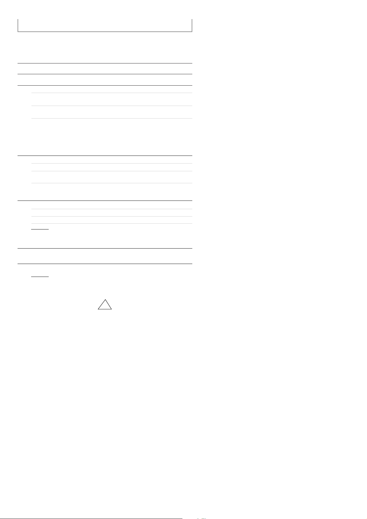
Installing the Software
You can install the device driver for DOS or for Windows
¡ Do not install DOS Driver when the program of Windows 95 is going on.
(Remark CD-ROM Driver in the state of Config. Sys.)
1
Turn on your computer and wait for it to boot.
2
Insert the driver disk into a floppy disk drive(usually the A drive).
3
If you are a...
DOS user
Windows user
Windows 95user
Then :
◆ Type a: at the DOS prompt
◆ Press the RETURN key
◆ Access the File Manager
◆ Click on the A icon.
◆
Type CDSETUP after the a: prompt
◆ Press RETURN
Double-click CDSETUP.EXE from the Windows
File Manager
◆ When you are in Windows 95, it is not
◆ necessary to install Device Driver.
◆ Whereas, when you are in Dos Mode of
◆ Windows 95, then install as follows.
◆ Click on MY COMPUTER icon.
◆ Click on the A icon.
4
5
6
Run the CDSETUP program:
To...
Confirm the installation Y
Exit without installing N
When the Setup Completed screen is displayed, remove the
installation floppy disk from the drive.
7
Reboot your system.
If you answer Y(Yes), the installation program automatically
◆ Creates a SAMSUNG directory on your hard disk
◆ Copies the required softwares (mscdex.exe and sscdrom.sys)
◆ Modifies the CONFIG.SYS and AUTOEXEC.BAT files
Result :
◆
The computer restarts
◆
Both the device driver and MSCDEX are loaded
Result :
Then enter...
If you are a...
Then :
DOS user
Windows user
Page 7

6
Resolving Technical Problems
☛ Please consult the following table BEFORE contacting your dealer or local SAMSUNG
☛ representative.
The software installation failed ◆ Check that your hard disk is not full
◆ The installation floppy disk may be corrupted.
Repeat the installation with the backup floppy disk.
After installing the device driver, your system start-up
program may take more time than expected. If it does not
start-up after 60 seconds, verify your AUTOEXEC. BAT file
and, if necessary, contact your local computer dealer.
I re-booted my PC and it paused during
the start-up program.
Problem Meaning / Solution
◆ When the program of Windows 95 is broken up, re-stall
◆ it as the computer can not read the program anymore.
◆ Verify the connections between the drive and your PC.
◆ Check that the 40-pin flat cable is connected to an IDE
◆ interface (some PCs are equipped with an SCSI disk
◆ interface)
◆ Verify your AUTOEXEC. BAT file. Go to page 6 for
◆ the verification procedure.
◆ Check the LASTDRIVE = command in the CONFIG. SYS
◆ file. The specified letter must take the CD-ROM volume
◆ into account. If you do not know which letter is assigned
◆ to the CD-ROM, enter Z.
◆ Using the documentation provided with your PC, check
◆ that the IDE hard disk is set up in MASTER mode.
I installed the software and rebooted my PC. The CD-ROM drive
icon/directory still does not appear.
The drive may not be installed correctly. Verify the
physical installation.
The disc tray does not open.
If you have installed the
CD-ROM drive ...
Then ...
And the software Re-boot your PC.
Install the software
following the instructions
on page 5
In the File Manager, the CD-ROM icon
does not display.
And have not installed the
software
Page 8
7
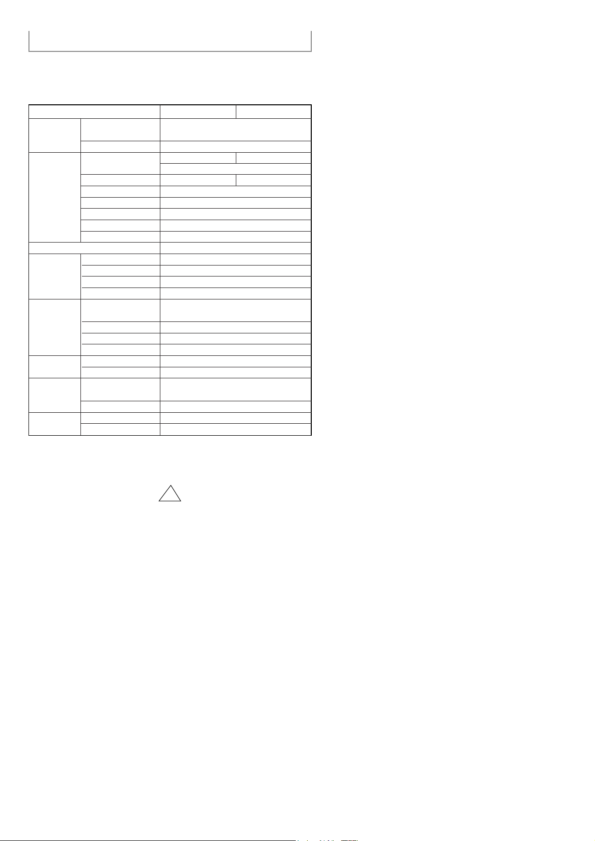
Technical Specifications
Max. 6000KB/s Max. 7200KB/s
SC-140 SC-148SECTIONS
DISC
DRIVE PER FORMANCE
FRONT PANEL
REAR PANEL
OPERATING
ENVIRONMENT
GENERAL
RELIABILITY
ERROR RATE
Disc types supported
Disc diameter
Data transfer rate
Access time (1/3 stroke)
Data buffer capacity
Laser
Slide mechanism
Spindle motor
Loading type
Button
Indicator(LED)
Headphone output
Volume control
Required power
Interface connector
Audio output
Jumper block
Work area
Storage area
Dimensions
Net weight
MTBF
Disc compartment loading
CD-DA, CD-ROM Mode-1, CD-ROM XA Mode-2 Form-1,
Form-2, CD-Plus, CD-Extra, Photo-CD(Single, Multi-session), Video
CD ready, Enhanced CD, CD-I/FMV, CD-R
12cm or 8cm
PIO Mode - 4. DMA MW2(option), Ultra DMA
80ms(typical) 70ms(typical)
128KB
Semiconductor Laser
Gear motor
Brushless motor
Tray Loading, DC motor(Soft Eject)
Mode-1 : 1block / 10 bits, Mode-2 : 1 block/10 bits
PLAY(Open/Close)
Busy
Stereo Mini - jack (Ø 3,6 mm) 0.60 ±20% (Vrms) 33Ω
Dial type
+5V DC 1.7A,
+12V DC 1.0A (Max)
ATAPI
Line out 0.70 ± 20%(Vrms), 47kΩ
Device configuration jumper
Temperature : 5~45 °C, Humidity : 8~80%
Temperature : -40~60 °C, Humidity : 5~90%
950g
125,000 POH(Duty 25%)
30,000 times
149(W) x 42.5(H) x 200(D)mm
(Including bezel)
SAMSUNG continually strives to improve its products. Both the design
specifications and these user instructions are thus subject to change without
notice.
12 9
 Loading...