

Samsung SC09AWH, SC09ZWH, AS09WHWE, AS09WHWD, KF-25G/SWA Service Manual
...
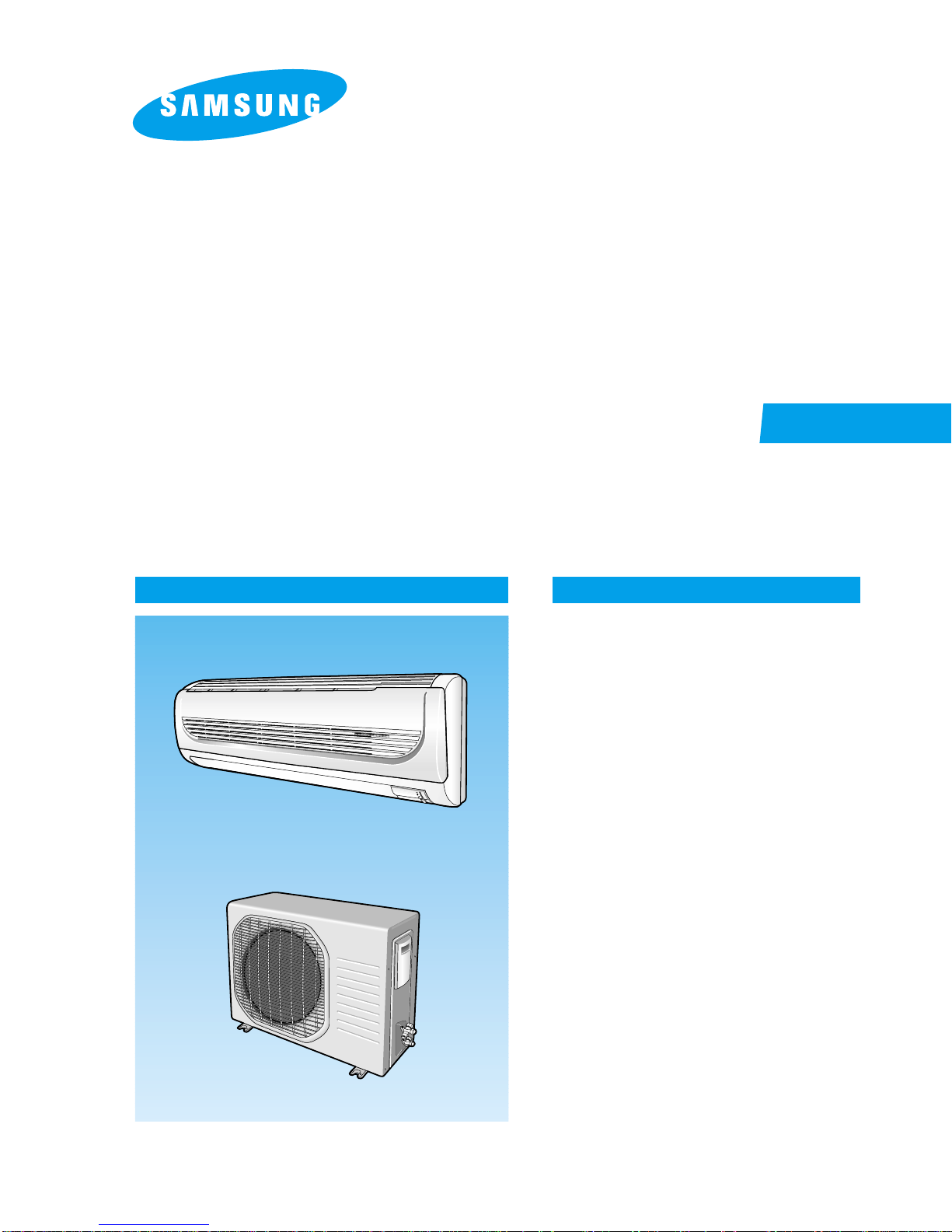
ROOM AIR CONDITIONER
INDOOR UNIT
SC09AWH
SC09ZWH
AS09WHWE
AS09WHWD
KF-25G/SWA
SC12AWH
SC12ZWH
AS12WHWE
AS12WHWD
KF-35G/SWA
SERVICE
OUTDOOR UNIT
SC09AWHX
SC09ZWHX
US09WHWE
US09WHWD
KF-25W/SWA
SC12AWHX
SC12ZWHX
US12WHWE
US12WHWD
KF-35W/SWA
Manual
CONTENTSAIR CONDITIONER
1. Product Specifications
2. Disassembly and Reassembly
3. Refrigerating Cycle Diagram
4. Set Up the Model Option
5. T roubleshooting
6. Exploded Views and Parts List
7. Block Diagram
8. Wiring Diagram
9. Schematic Diagram

ELECTRONICS
This Service Manual is a property of Samsung Electronics Co., Ltd.
Any unauthorized use of Manual can be punished under applicable
International and/or domestic law.
© Samsung Electronics Co., Ltd. Apr. 2004.
Printed in Korea.
Code No. DB98-16569A(2)
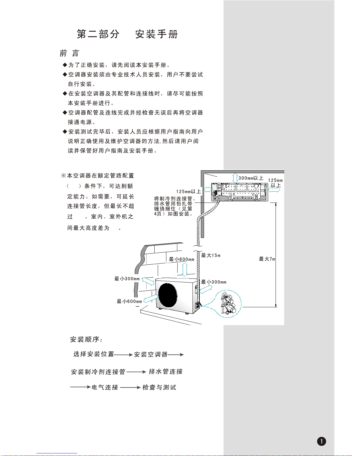
4m
15m
7m
ROOM AIR CONDITIONER
INDOOR UNIT
SC09AWH
SC09ZWH
AS09WHWE
AS09WHWD
KF-25G/SWA
SC12AWH
SC12ZWH
AS12WHWE
AS12WHWD
KF-35G/SWA
SERVICE
OUTDOOR UNIT
SC09AWHX
SC09ZWHX
US09WHWE
US09WHWD
KF-25W/SWA
SC12AWHX
SC12ZWHX
US12WHWE
US12WHWD
KF-35W/SWA
Manual
CONTENTSAIR CONDITIONER
1. Product Specifications
2. Disassembly and Reassembly
3. Refrigerating Cycle Diagram
4. Set Up the Model Option
5. T roubleshooting
6. Exploded Views and Parts List
7. Block Diagram
8. Wiring Diagram
9. Schematic Diagram
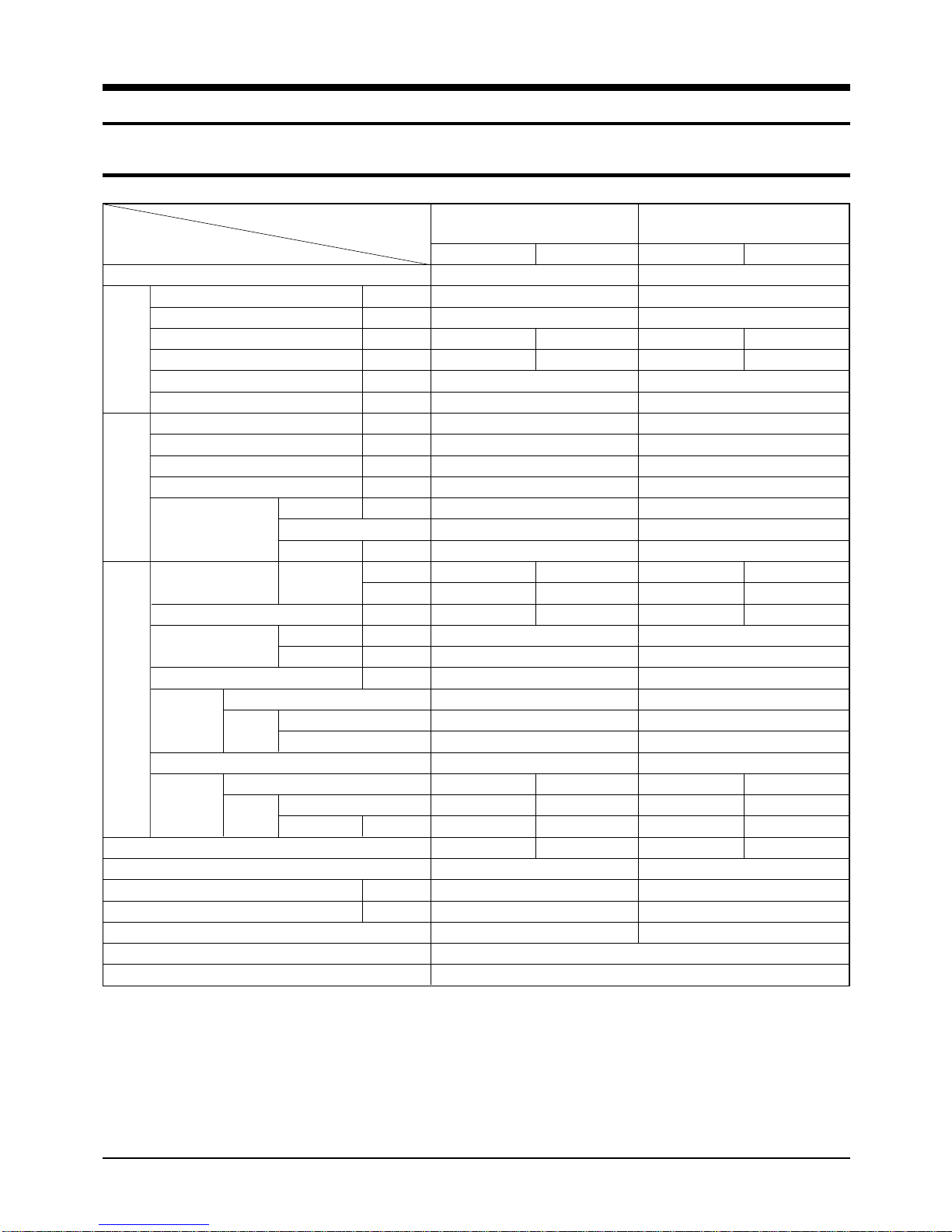
1. Product Specifications
1-1 Table
Item
Type
Cooling kW
Dehumidifying |/h
Air Volume m
Performance
Noise dB
Energy Efficiency Ratio W/W
Power V-Hz
Power Consumption W
Operating Current A
Power Factor %
Starting Current A
Power
Length m
Power Cord Number of Core Wire
Capacity A
Outer Dimension W x H x D
Weight(Net) kg
Refrigerant Pipe
Drain Hose D x L(mm)
Size
Compressor Motor Type
Oil Type
Blower Motor Type
Heat Exchanger
Refrigerant Control Unit
Freezer Oil Capacity cc
Refrigerant to Change(R410A) g
Protection Device(OLP)
Cooling Test Condition
Maximum Operation Condition
Type
Type
Liquid mm x L(m)
GAS mm x L(m)
Rated Output
Rated Output W
Model
3
/min
mm
inch
SC09AWH
Indoor unit Outdoor unit
Wall-mounted
2.7
1.0
7.3 25
38 / 36 / 34 51 / 51
2.70
1-220 / 240-50
1,000
4.5
98.2
21.0
-
-
250V-10A
825x285x189 720x548x265
32.5x11.2 x7.44 28.4x21.6x10.4
8.2 33.0
ø6.35 x 7.5
ø9.52 x 7.5
ø18 x 550
Rotary
Induction Motor(PSC)
900
DAPHNE FV68S(PVE)
Cross-flow Propeller
steel steel
15 50
2ROW 14STEP 1ROW 24STEP
CAPILLARY TUBE
350
580
MRA99134-9201
INDOOR UNIT : DB27˚C WB19˚C OUTDOOR UNIT : DB35˚C WB24˚C
INDOOR UNIT : DB32˚C WB23˚C OUTDOOR UNIT : DB43˚C WB28˚C
Indoor unit Outdoor unit
41 / 39 / 37 53 / 53
825x285x189 720 x 548 x 265
32.5x11.2x7.44 28.4x21.6x10.4
Cross-flow Propeller
2ROW 14STEP 1ROW 24STEP
SC12AWH
Wall-mounted
3.5
1.4
8.3 25
2.99
1-220 / 240-50
1,170
5.7
96.9
30.0
-
-
250V-10A
8.4 33.8
ø6.35 x 7.5
ø9.52 x 7.5
ø18 x 550
Rotary
Induction Motor(PSC)
1,075
DAPHNE FV68S(PVE)
steel steel
15 50
CAPILLARY TUBE
520
830
MRA99908-9201
1Samsung Electronics
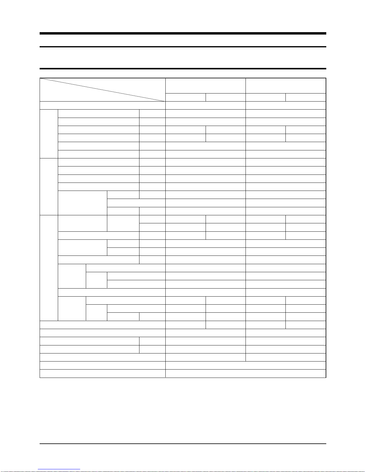
Table(cont.)
Item
Type
Cooling kW
Dehumidifying |/h
Air Volume m
Perfor-
mance
Noise dB
Energy Efficiency Ratio W/W
Power V-Hz
Power Consumption W
Operating Current A
Power Factor %
Starting Current A
Power
Length m
Power Cord Number of Core Wire
Capacity A
Outer Dimension W x H x D
Weight(Net) kg
Refrigerant Pipe
Drain Hose D x L(mm)
Size
Compressor Motor Type
Oil Type
Blower Motor Type
Heat Exchanger
Refrigerant Control Unit
Freezer Oil Capacity cc
Refrigerant to Change(R22) g
Protection Device(OLP)
Cooling Test Condition
Maximum Operation Condition
Type
Type
Liquid mm x L(m)
GAS mm x L(m)
Rated Output
Rated Output W
Model
3
/min
mm
inch
SC09ZWH/AS09WHWE
Indoor unit Outdoor unit
Wall-mounted
2.7
1.0
7.3 25
38 / 36 / 34 51 / 51
2.70
1-220 / 240-50
1,000
4.5
98.2
21.0
-
-
250V-10A
825x285x189 720x548x265
32.5x11.2 x 7.44 28.4x21.6x10.4
8.2 33.0
ø6.35 x 5.0
ø9.52 x 5.0
ø18 x 550
Rotary
Induction Motor(PSC)
1,005
SUNISO-4GSD
Cross-flow Propeller
steel steel
15 50
2ROW 14STEP 1ROW 24STEP
CAPILLARY TUBE
360
580
RAC12110-9622
INDOOR UNIT : DB27˚C WB19˚C OUTDOOR UNIT : DB35˚C WB24˚C
INDOOR UNIT : DB32˚C WB23˚C OUTDOOR UNIT : DB43˚C WB28˚C
SC12ZWH/AS12WHWE
Indoor unit Outdoor unit
Wall-mounted
3.5
1.4
8.3 25
41 / 39 / 37 53 / 53
2.99
1-220 / 240-50
1,170
5.2
96.9
30.0
-
-
250V-10A
825x285x189 720x548x265
32.5x11.2 x7.44 28.4x21.6x10.4
8.4 33.8
ø6.35 x 5.0
ø12.7 x 5.0
ø18 x 550
Rotary
Induction Motor(PSC)
1,206
SUNISO-4GSD
Cross-flow Propeller
steel steel
15 50
2ROW 14STEP 1ROW 24STEP
CAPILLARY TUBE
600
830
RAC12074-9622
Samsung Electronics2
Item
Type
Cooling kW
Dehumidifying |/h
Air Volume m
Performance
Noise dB
Energy Efficiency Ratio W/W
Power V-Hz
Power Consumption W
Operating Current A
Power Factor %
Starting Current A
Power
Length m
Power Cord Number of Core Wire
Capacity A
Outer Dimension W x H x D
Weight(Net) kg
Refrigerant Pipe
Liquid mm x L(m)
GAS mm x L(m)
Drain Hose D x L(mm)
Size
Type
Compressor Motor Type
Rated Output
Oil Type
Type
Blower Motor Type
Rated Output W
Heat Exchanger
Refrigerant Control Unit
Freezer Oil Capacity cc
Refrigerant to Change(R22) g
Protection Device(OLP)
Cooling Test Condition
Maximum Operation Condition
Model
3
/min
mm
inch
AS09WHWD
Indoor unit Outdoor unit
Wall-mounted
2.65
1.0
7.3 25
38 / 36 / 34 51 / 51
2.82
1-220-50
940
4.6
97.0
21.0
-
-
250V-10A
825x285x189 720x548x265
32.5x11.2 x7.44 28.4 x21.6x10.4
8.2 33.0
ø6.35 x 5.0
ø9.52 x 5.0
ø18 x 550
Rotary
Induction Motor(PSC)
1,005
SUNISO-4GSD
Cross-flow Propeller
steel steel
15 50
2ROW 14STEP 1ROW 24STEP
CAPILLARY TUBE
360
580
RAC12054-9622
Indoor unit Outdoor unit
41 / 39 / 37 53 / 53
825x285x189 720x548x265
32.5x11.2 x7.44 28.4 x21.6x10.4
Cross-flow Propeller
2ROW 14STEP 1ROW 24STEP
AS12WHWD
Wall-mounted
3.5
1.4
8.3 25
2.99
1-220-50
1,170
5.8
92.0
30.0
-
-
250V-10A
8.4 33.8
ø6.35 x 5.0
ø12.7 x 5.0
ø18 x 500
Rotary
Induction Motor(PSC)
1,206
SUNISO-4GSD
steel steel
15 50
CAPILLARY TUBE
600
920
RAC12074-9622
INDOOR UNIT : DB27˚C WB19˚C OUTDOOR UNIT : DB35˚C WB24˚C
INDOOR UNIT : DB32˚C WB23˚C OUTDOOR UNIT : DB43˚C WB28˚C
3Samsung Electronics 3Samsung Electronics
Table(cont.)
Item
Type
Cooling kW
Dehumidifying |/h
Air Volume m
Perfor-
mance
Noise dB
Energy Efficiency Ratio W/W
Power V-Hz
Power Consumption W
Operating Current A
Power Factor %
Starting Current A
Power
Length m
Power Cord Number of Core Wire
Capacity A
Outer Dimension W x H x D
Weight(Net) kg
Refrigerant Pipe
Drain Hose D x L(mm)
Size
Compressor Motor Type
Oil Type
Blower Motor Type
Heat Exchanger
Refrigerant Control Unit
Freezer Oil Capacity cc
Refrigerant to Change(R22) g
Protection Device(OLP)
Cooling Test Condition
Maximum Operation Condition
Type
Type
Liquid mm x L(m)
GAS mm x L(m)
Rated Output
Rated Output W
Model
3
/min
mm
inch
KF-25G/SWA
Indoor unit Outdoor unit
Wall-mounted
2.65
1.0
7.3 25
38 / 36 / 34 51 / 51
2.82
1-220-50
940
4.6
97.0
21.0
-
-
250V-10A
835x285x189 720x548x265
32.5x11.2 x7.44 28.4 x21.6x10.4
8.2 33.0
ø6.35 x 4.0
ø9.52 x 4.0
ø18 x 550
Rotary
Induction Motor(PSC)
1,005
SUNISO-4GSD
Cross-flow Propeller
steel steel
15 50
2ROW 14STEP 1ROW 24STEP
CAPILLARY TUBE
360
580
RAC12054-9622
INDOOR UNIT : DB27˚C WB19˚C OUTDOOR UNIT : DB35˚C WB24˚C
INDOOR UNIT : DB32˚C WB23˚C OUTDOOR UNIT : DB43˚C WB28˚C
41 / 39 / 37 53 / 53
835x285x189 720x548x265
32.5x11.2 x7.44 28.4 x21.6x10.4
2ROW 14STEP 1ROW 24STEP
KF-35G/SWA
Indoor unit Outdoor unit
Wall-mounted
3.5
1.4
8.3 25
2.99
1-220-50
1,170
5.8
92.0
30.0
-
-
250V-10A
8.4 33.8
ø6.35 x 4.0
ø12.7 x 4.0
ø18 x 550
Rotary
Induction Motor(PSC)
1,206
SUNISO-4GSD
Cross-flow Propeller
steel steel
15 50
CAPILLARY TUBE
600
920
RAC12074-9622
Samsung Electronics4
2. Disassembly and Reassembly
Stop operation of the air conditioner and remove the power cord before repairing the unit.
2-1 Indoor Unit
No Parts Procedure Remark
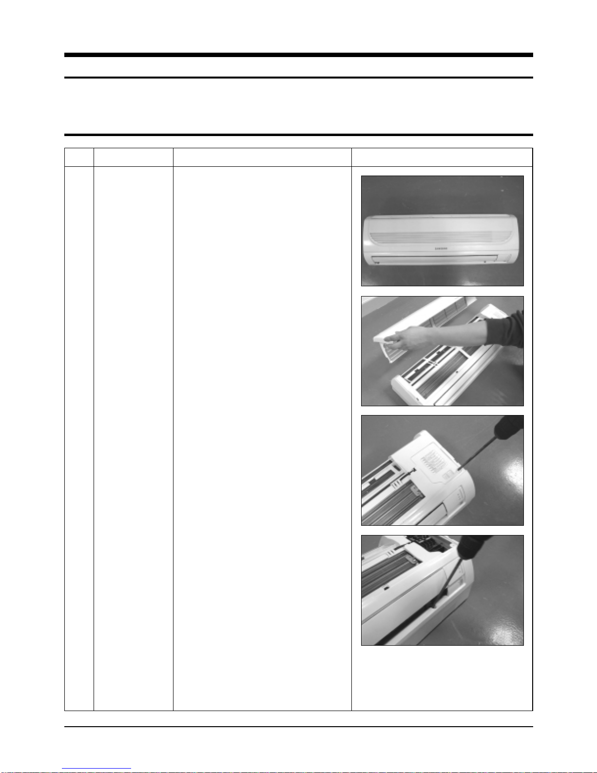
1 Front Grille
1) Stop the air conditioner operation and
block the main power.
2) Open the Front Grille by pulling right and
left sides of the hook.
3) Loosen 1 of the right screw and detach
the Terminal Cover.
4) Detach the thermistor from the Front
Grille.
5) Loosen 2 fixing screws of Front Grille.
5Samsung Electronics
Disassembly and Reassembly
No Parts Procedure Remark
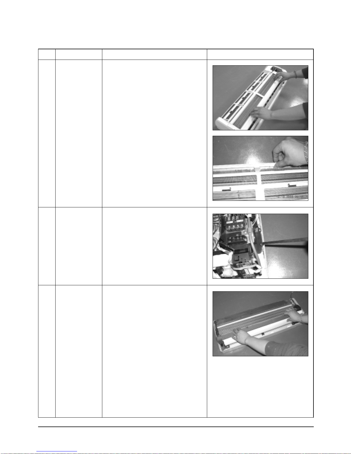
6) Unlock 2 hooks to fix Panel Front and
Tray Drain.
7) Unlock 3 hooks to fix Panel Front and
Back-Body.
2
Control-In
(Main PCB)
1) Take all the connector of PCB upper side
out. (Inclusion Power Cord)
2) Detach the outdoor unit connection wire
from the Terminal Block.
3) Loosen 4 fixing screws of Ass'y Control-In.
3
Tray Drain
1) Pull Tray Drain out from the Back Body.
Samsung Electronics6
Disassembly and Reassembly
No Parts Procedure Remark
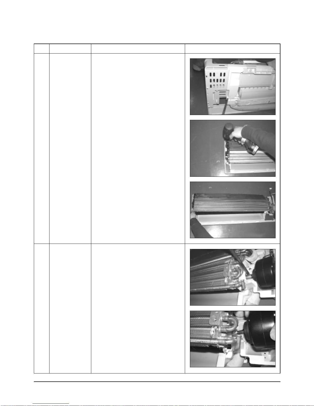
4
Heat Exchanger
1) Loosen 2 fixing earth screws of right side.
2) Detach the Connection Pipe.
3) Detach the Holder Pipe at the rear side.
4) Loosen the 3 fixing screws of right and left
side.
5) Lifting the Heat Exchanger up a little to
push the up side for separation from the
indoor unit.
5
Fan Motor
&
Cross Fan
1) Loosen the fixing screw and detach the
Motor Holder.
2) Detach the Fan Motor from the Fan.
3) Detach the Fan From the left Holder
Bearing.
7Samsung Electronics
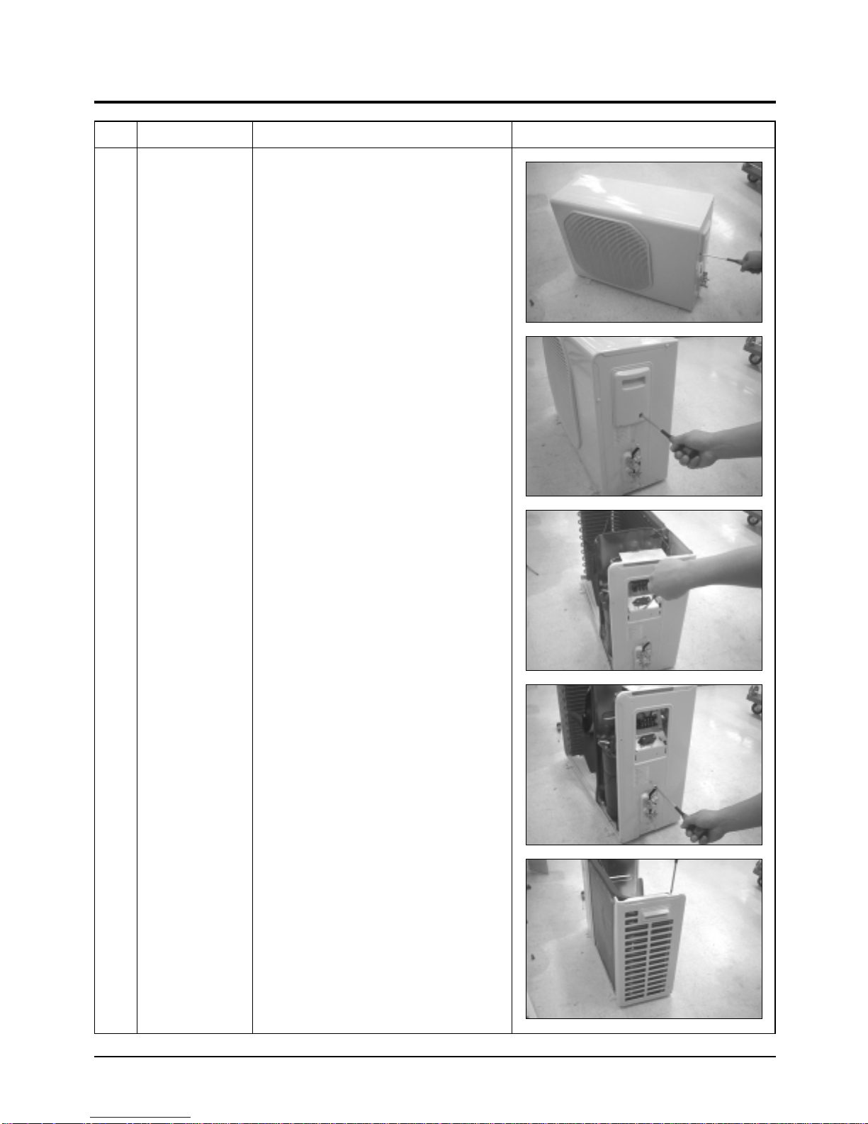
2-2 Outdoor Unit
No Parts Procedure Remark
1 Common Work
1) Loosen each 3 fixing screws on both right
and left Cabinet-Side edge and a fixing
screw on the Cabinet-Front lower to detach
the Cabinet-Front.
2) Loosen 2 fixing screws of the
Ass'y-Control.
3) Loosen 6 fixing screws of the Cabinet-Side
RH.
4) Loosen 2 fixing screws of the Cabinet-Side
LF.
Samsung Electronics8
Disassembly and Reassembly
No Parts Procedure Remark
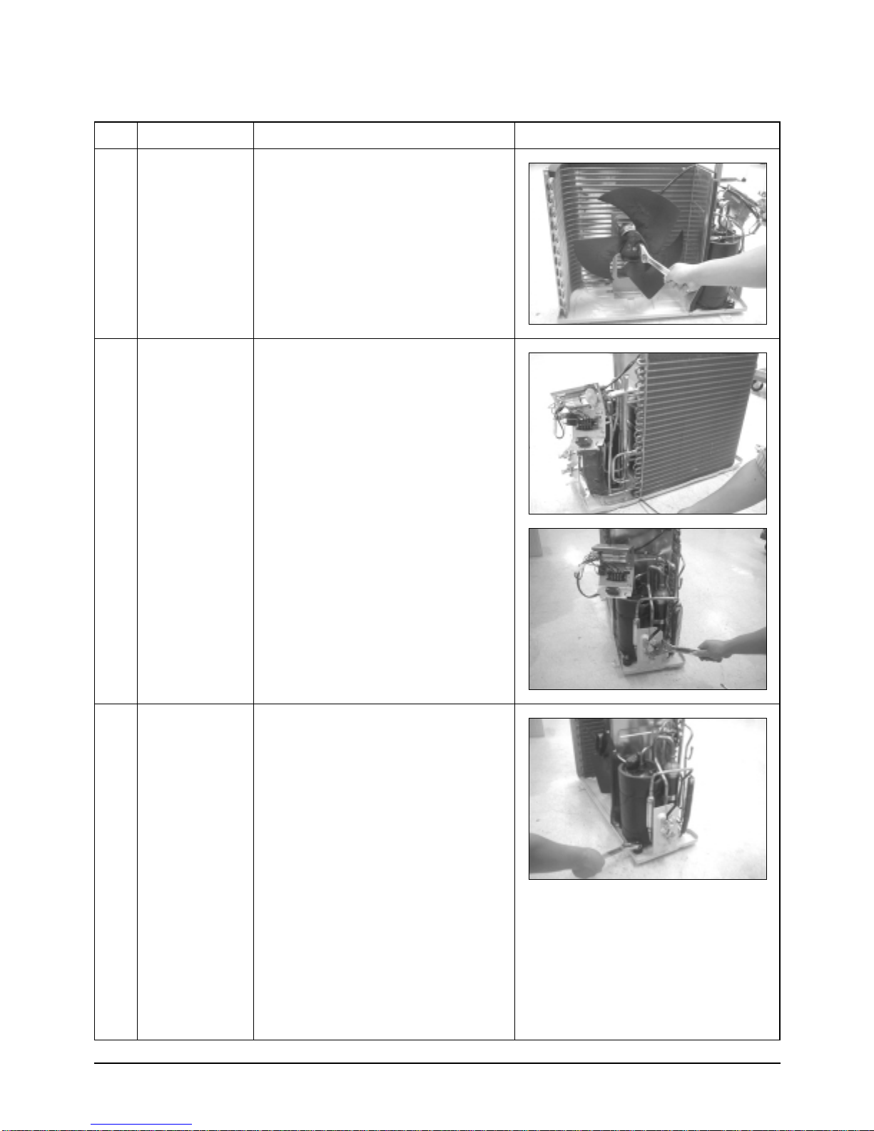
2
3
Fan
&
Motor
Heat Exchanger
1) Detach the Nut Flange.(Turn counterclockwise because the screw is right-handed)
2) Detach the Fan.
3) Loosen 4 fixing screws to detach
the Motor.
1) Loosen 2 fixing screws on both sides.
2) Disassemble the pipe in both inlet and
outlet with welding torch.
3) Detach the Heat Exchanger.
4
Compressor
1) Loosen the Terminal Cover nut to open the
Terminal Cover.
2) Disassemble the cloth sound felt.
3) Disassemble the pipe in both inlet and
outlet of the Compressor with welding
torch.
4) Disassemble the pipe in both inlet and
outlet of the Condenser with welding torch.
5) Loosen the 3 bolts at the bottom.
6) Detach the Compressor.
9Samsung Electronics
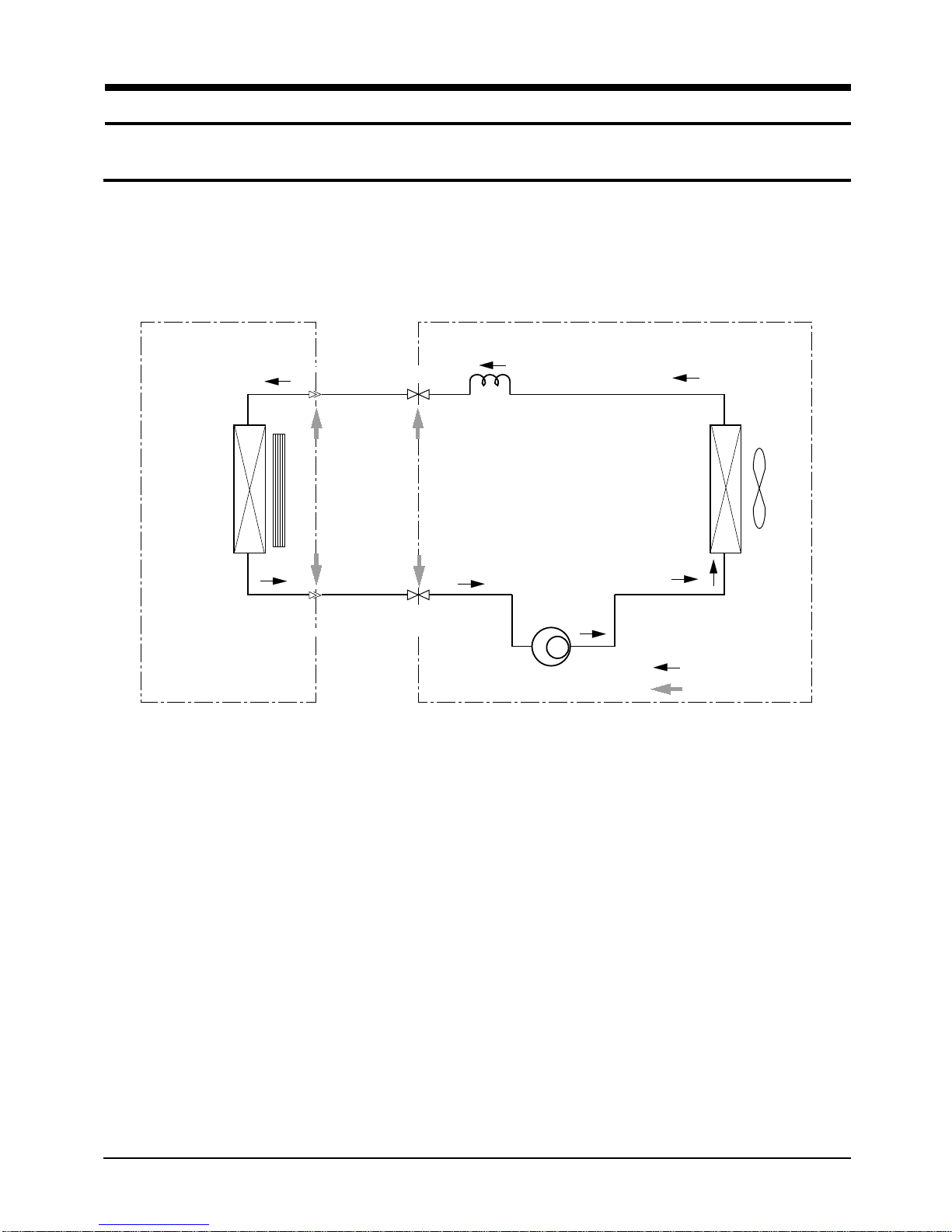
3. Refrigerating Cycle Diagram
3-1 Refrigerating Cycle Diagram
Indoor Unit
Heat
Exchanger
(Evaporator)
Outdoor Unit
Capillary tube
1
T
Liquid side
Cross fan
T2
Gas side
2-Way valve
3-Way valve
Compressor
Heat
Exchanger
(Condenser)
Propeller fan
Cooling
Gas Leak Check Point
Samsung Electronics10
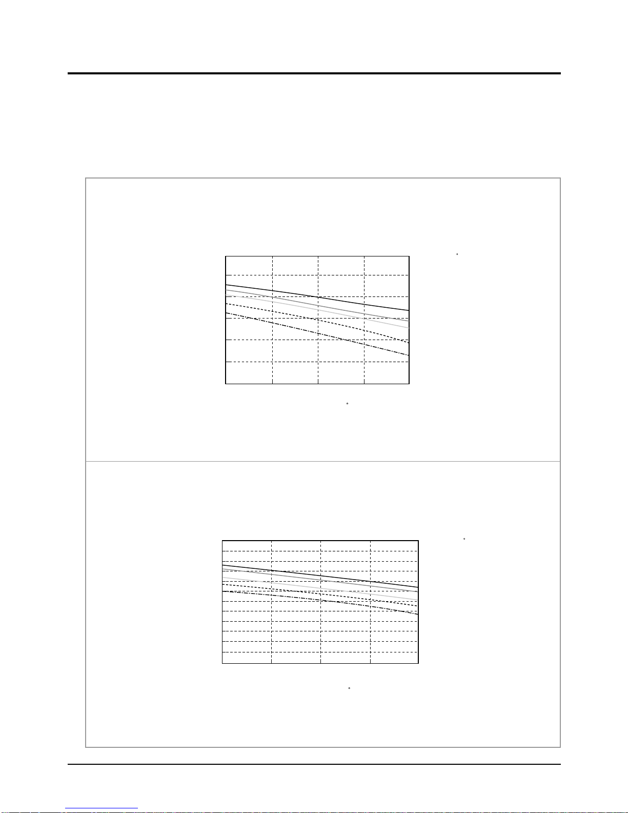
3-2 Refrigerant Cycle Characteristic
DB32.4/WB24.0
DB30.6/WB22.5
DB27.0/WB19.0
DB24.0/WB17.0
DB21.0/WB15.0
Cooling Capacity(kW)
Cooling Capacity Distribution
6.0
5.0
4.0
3.0
2.0
1.0
0.0
25 35 45
Outdoor Temp.(DB C)
Indoor Temp.( C)
3-2-1 Capacity Distributions
Capacity Distributions according to indoor and outdoor temperature variation.
- Indoor Temp. Variation : 21.0˚C ~ 32.4˚C
- Outdoor Temp. Variation : 25.0˚C ~ 45.0˚C
■ 9,000Btu
Cooling Capacity Distribution
■ 12,000Btu
4.0
3.0
2.0
Cooling Capacity(kW)
1.0
25.0 35.0 45.0
Outdoor Temp.(DB C)
Indoor Temp.( C)
DB32.4 / WB24.0
DB30.6 / WB22.5
DB27.0 / WB19.0
DB24.0 / WB17.0
DB21.0 / WB15.0
11Samsung Electronics
Refrigerating Cycle Diagram
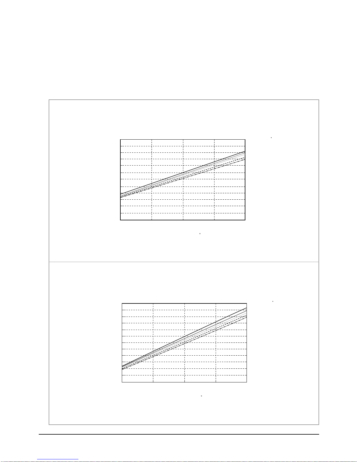
3-2-2 Power Consumption Distributions
Power Consumption Distributions according to indoor and outdoor temperature variation.
- Indoor Temp. Variation : 21.0˚C ~ 32.4˚C
- Outdoor Temp. Variation : 25.0˚C ~ 45.0˚C
■ 9,000Btu
Power consumption Distribution(Cooling mode)
■ 12,000Btu
1,300
1,200
1,100
1,000
900
Power consumption(W)
800
700
25 35 45
1,600
1,500
Outdoor Temp.(DB C)
Power consumption Distribution(Cooling mode)
Indoor Temp.( C)
DB32.4 / WB24.0
DB30.6 / WB22.5
DB27.0 / WB19.0
DB24.0 / WB19.0
DB21.5 / WB15.0
Indoor Temp.( C)
DB32.4 / WB24.0
DB30.6 / WB22.5
DB27.0 / WB19.0
DB24.0 / WB19.0
DB21.5 / WB15.0
1,400
1,300
1,200
Power consumption(W)
1,100
1,000
25 35 45
Outdoor Temp.(DB C)
Samsung Electronics12
Refrigerating Cycle Diagram
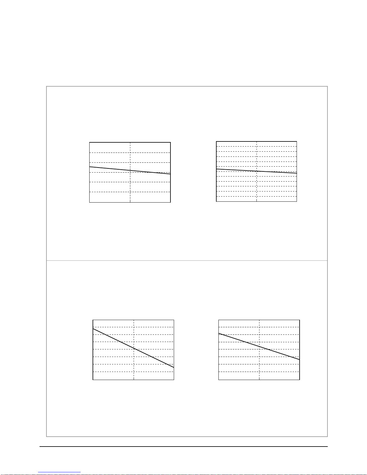
3-2-3 Capacity and Power Consumption Distributions
Capacity and power Consumption distributions according to the length of connecting Pipe between indoor unit and outdoor unit.
■ 9,000Btu
4
3
2
Coooling Capacity(kW)
1
■ 12,000Btu
Cooling Capacity
7.5 15.0
Length of Connecting Pipe(m)
Power consumption(Cooling)
1,300
1,200
1,100
1,000
900
800
Power consumption(W)
700
7.5 15.0
Length of Connecting Pipe(m)
Cooling Capacity
3.70
3.50
3.30
3.10
Cooling Capacity(kW)
2.90
7.5 15.0
Length of Connecting Pipe(m)
Power consumption(Cooling)
1,350
1,300
1,250
1,200
Power consumption(W)
1,150
7.5 15.0
Length of Connecting Pipe(m)
13Samsung Electronics
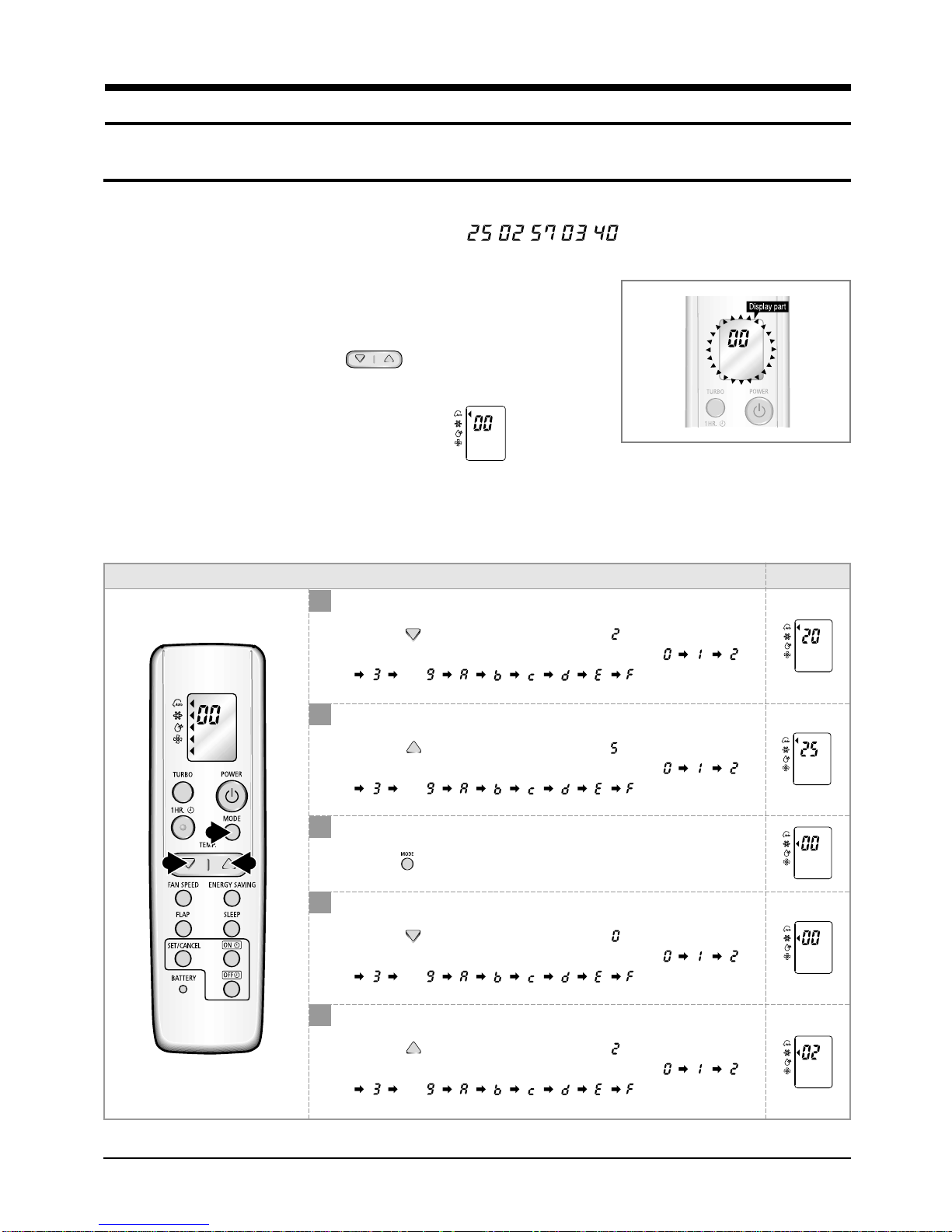
4. Set Up the Model Option
4-1 Setting Option Setup Method
ex) Option No. :
Step 1 : Enter the Option Setup mode.
st
1
nd
2
Take out the batteries of remote control.
Press the temperature button simultaneously and
insert the battery again.
rd
3
Make sure the remocon display shown as .
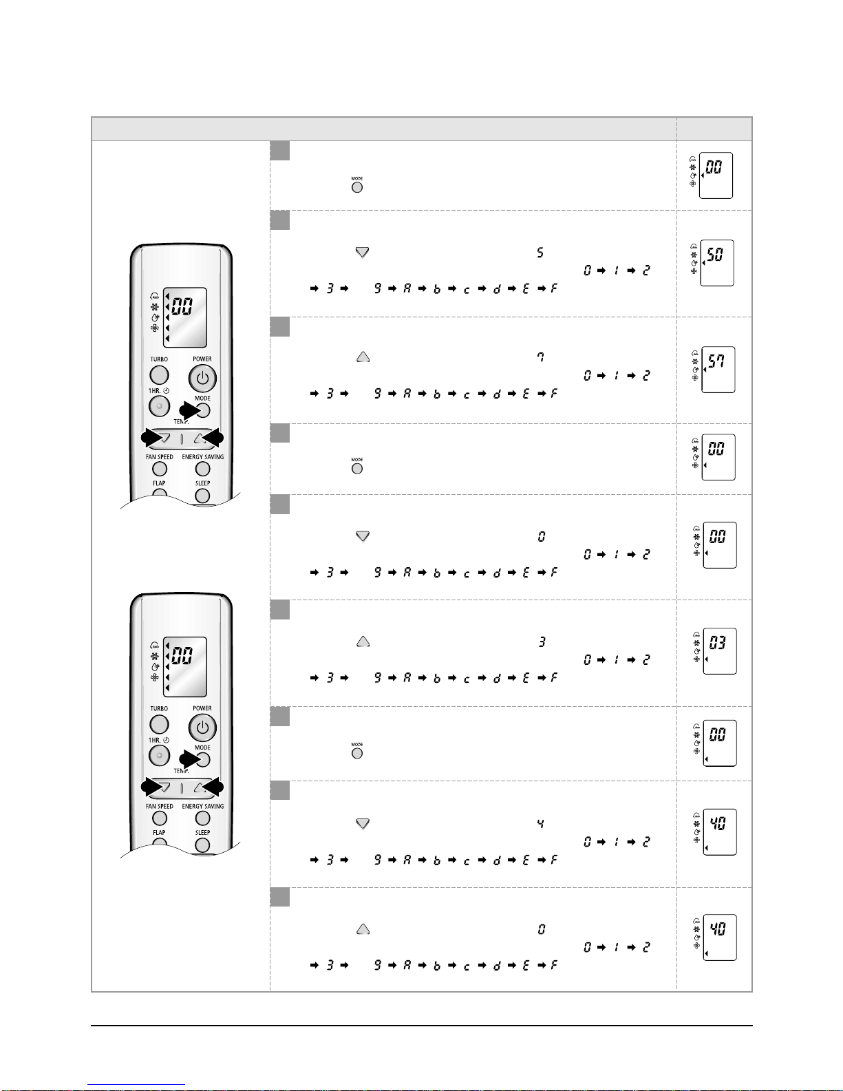
Step 2 : Enter the Option Setup mode and select your option according to the following procedure.
Feature Display
1
Setting Option SEG1.
Push the button to set the display panel to .
Every time you push the button, the display panel reads
3
1,4 2,5
. . .
2
Setting Option SEG2.
Push the button to set the display panel to .
Every time you push the button, the display panel reads
. . .
3
Change it into the set display of Option SEG3 and SEG4
with the button.
repeatedly.
repeatedly.
4
5
Setting Option SEG3.
Push the button to set the display panel to .
Every time you push the button, the display panel reads
. . .
Setting Option SEG4.
Push the button to set the display panel to .
Every time you push the button, the display panel reads
. . .
repeatedly.
repeatedly.
Samsung Electronics14
Feature Display
6,9
7,10 8,11
12
13 14
6
Change it into the set display of Option SEG5 and SEG6
with the button.
7
Setting Option SEG5.
Push the button to set the display panel to .
Every time you push the button, the display panel reads
. . .
8
Setting Option SEG6.
Push the button to set the display panel to .
Every time you push the button, the display panel reads
. . .
9
Change it into the set display of Option SEG7 and SEG8
with the button.
Set Up the Model Option
repeatedly.
repeatedly.
10
Setting Option SEG7.
Push the button to set the display panel to .
Every time you push the button, the display panel reads
. . .
11
Setting Option SEG8.
Push the button to set the display panel to .
Every time you push the button, the display panel reads
. . .
12
Change it into the set display of Option SEG9 and SEG10
with the button.
13
Setting Option SEG9.
Push the button to set the display panel to .
Every time you push the button, the display panel reads
. . .
14
Setting Option SEG10.
Push the button to set the display panel to .
Every time you push the button, the display panel reads
. . .
repeatedly.
repeatedly.
repeatedly.
repeatedly.
15Samsung Electronics
Set Up the Model Option
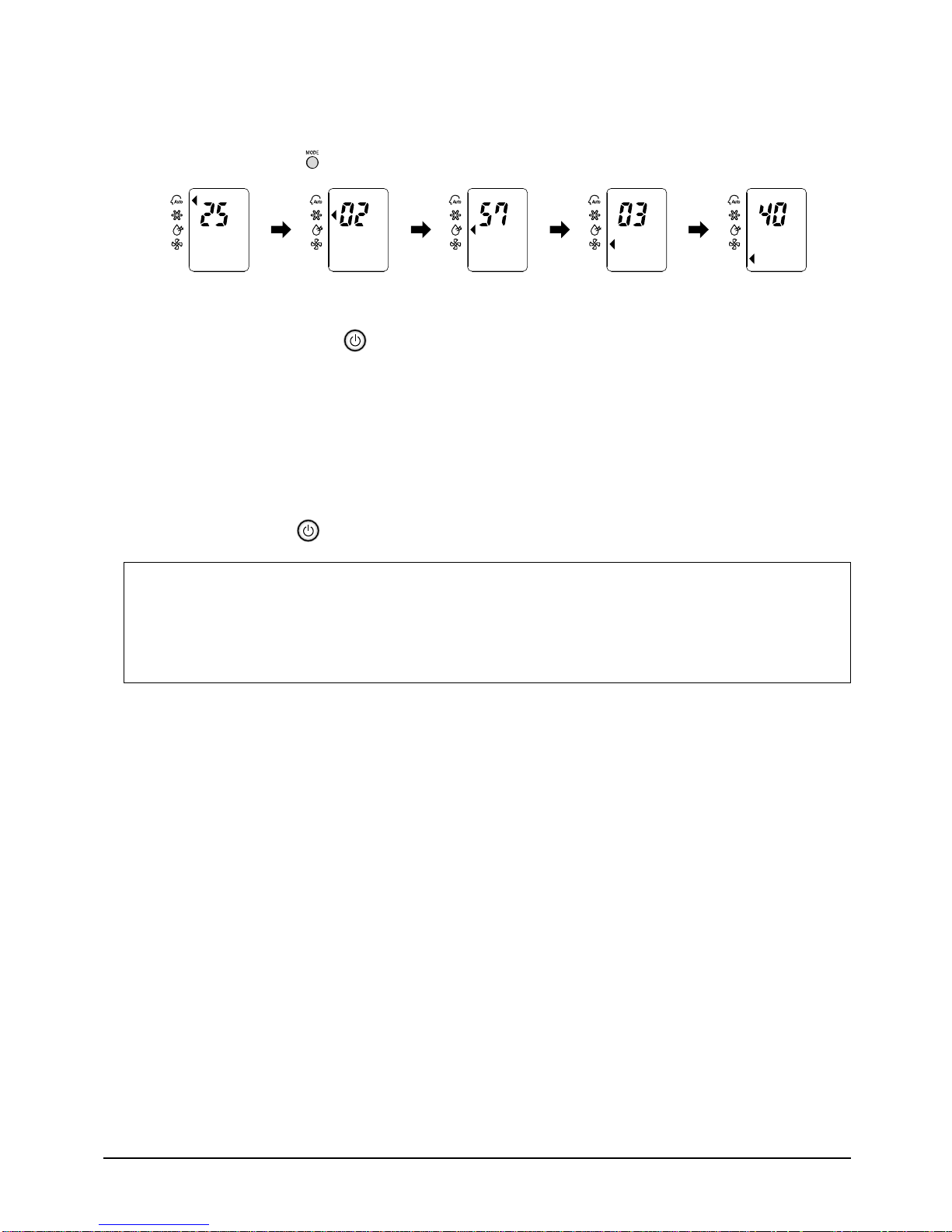
Step 3 : Upon completion of the selection, check you made right selections.
Whenever you press the button, the set Option will be displayed.
Step 4 : Pressing the ON/OFF button ( )
When pressing the operation ON/OFF key with the direction of remote controller for unit, the sound "Ding" is heard and the
OPERATION LED lamp is flickering at the same time, then the input of option is completed. (If the "ding" sound isn't heard,
try again pressing the ON/OFF button.)
Step 5 : Unit operation test-run
First, Remove the battery from the remote controller.
Second, Re-insert the battery into the remote controller.
Third, Press ON/OFF ( ) key with the direction of remote controller for set.
• Error Mode
st
1
If all lamps of indoor unit are flickering, Plug out, plug in power plug again and press ON/OFF key to retry.
nd
2
If the unit is not working properly or all lamps are continuously flickering after setting the option code, see if the
correct option code is set up for its model.
Samsung Electronics16
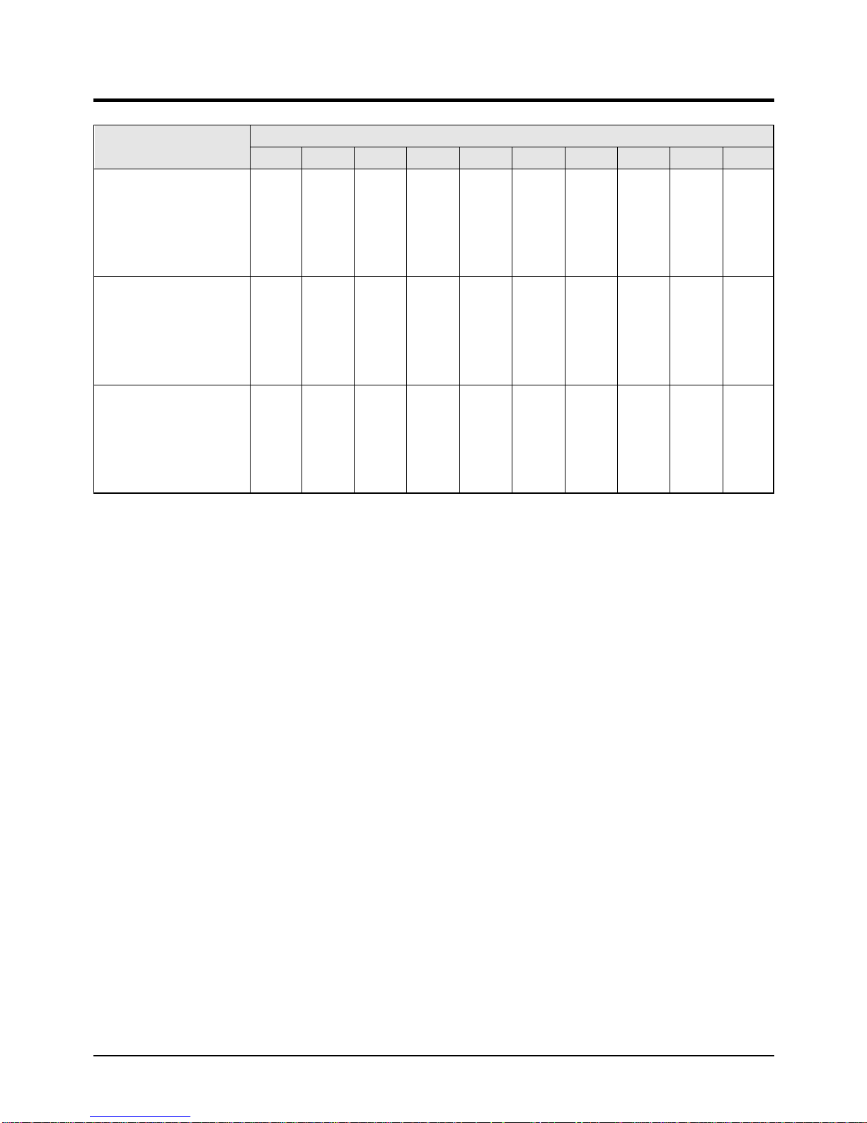
4-2 Table of the option Code
Model
SC09AWH
SC09ZWH
AS09WHWD
AS09WHWE
KF-25G/SWA
SC12AWH
SC12ZWH
AS12WHWD
AS12WHWE
KF-35G/SWA
Option Code
SEG1 SEG2 SEG3 SEG4 SEG5 SEG6 SEG7 SEG8 SEG9 SEG10
20000A00c8
20000A00Fb
20000A0340
17Samsung Electronics
5. Troubleshooting
Check the basic items first to judge if the problem was caused by breakdown or misuse. If none of the basic items are related to the
problem, please scrutinize the machine according to the 'Breakdown Diagnosis by Symptoms' method.
5-1 Basic Breakdown Diagnosis Items
1. The input voltage should be rating voltage ±10% range.
The airconditioner may not operate properly if the voltage is out of this range.
2. Is the link cable linking the indoor unit and the outdoor unit linked properly?
The indoor unit and the outdoor unit shall be linked by 5 cables.
Check the terminals if the indoor unit and outdoor unit are properly linked by the same number of cables.
Otherwise the airconditioner may not operate properly.
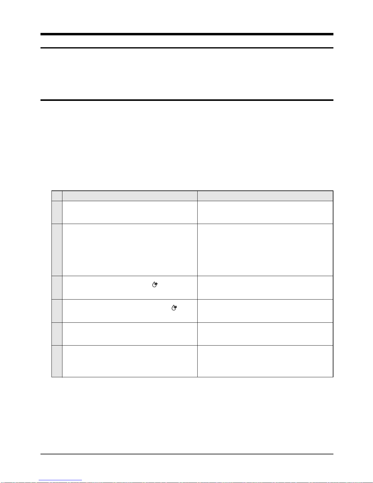
3. When a problem occurs due to the contents illustrated in the table below it is a symptom not related to the malfunction of the
airconditioner.
No
1
The OPERATION indication LED(GREEN) blinks when a
power plug of the indoor unit is plugged in for the first time.
2
In a COOL operation mode, the compressor does not
operate at a room temperature higher than the setting
temperature that the INDOOR FAN should operate.
3
Fan speed setting is not allowed in DRY( ) mode.
4
Compressor stops operation intermittently in DRY( )
mode.
5
Timer LED(GREEN) of the indoor unit lights up and the
air conditioner does not operate.
6
The compressor stops intermittently in a COOL mode or
DRY mode, and fan speed of the indoor unit decreases.
Operation of air conditioner Explanation
It indicates power is on. The LED stops blinking if the operation ON/OFF button on the remote control unit is pushed.
In happens after a delay of 3 minutes when the compressor
is reoperated. The same phenomenon occurs when a power
is on.
As a phenomenon that the compressor is reoperated after a
delay of 3 minutes, the indoor fan is adjusted automatically
with reference to a temperature of the air blew.
The speed of the indoor fan is set to LL in DRY mode.
Fan speed is selected automatically in AUTO mode.
Compressor operation is controlled automatically in DRY
mode depending on the room temperature and humidity.
Timer is being activated and the unit is in ready mode.
The unit operates normally if the timer operation is cancelled.
The compressor stops intermittently or the fan speed of the
indoor unit decreases to prevent inside/outside air frozen
depending on the inside/outside air temperature.
Samsung Electronics18
5-2 Trouble check in the initial status
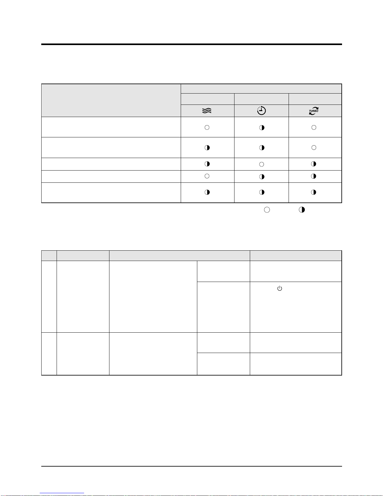
5-2-1 Diagnosis and marking of the part in trouble.
Please check the air conditioner operation status and write the check result in the chart in the room.
LAMP
Description
Indoor unit room temperature sensor error
(open or short)
Indoor unit heat exchanger temperature sensor error
(open or short)
Indoor fan motor mal function
EEPROM error
Option error
(option wasn't set up or option data error)
OPERATION TIMER TURBO
: Lamp off
5-2-2 Operation with abnormal motion
No Abnormal condition Inspection Initial Diagnosis
1
No response from
the remote control
operation signal.
2
Unable to operate the
outdoor unit
• Plug out and plug in 5 seconds later.
• Press the TURBO button with the
remote control.
• In 3 minutes, check the voltage
between the indoor unit terminal
block N(1) and 1.
Able to operate the
remote control.
Unable to operate
the remote control.
AC200V ~ AC240V
No power source
displayed.
OK
Press the button in the indoor unit.
• If it operates, the remote control and
indoor unit receiver are in trouble.
• If not, the indoor unit is in trouble.
Problem with the outdoor unit or PCB
Problem with the relay (RY71) or PCB
: Lamp flickering
19Samsung Electronics
5-3 Breakdown diagnosis by symptoms
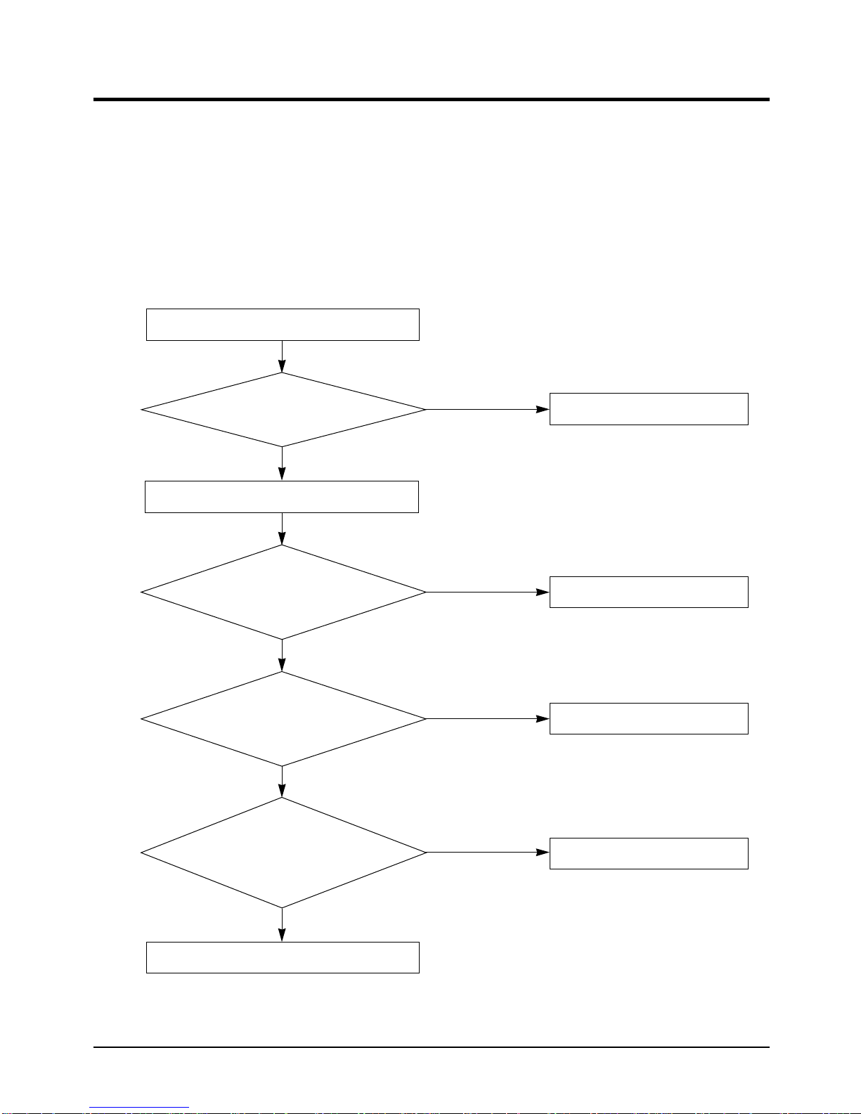
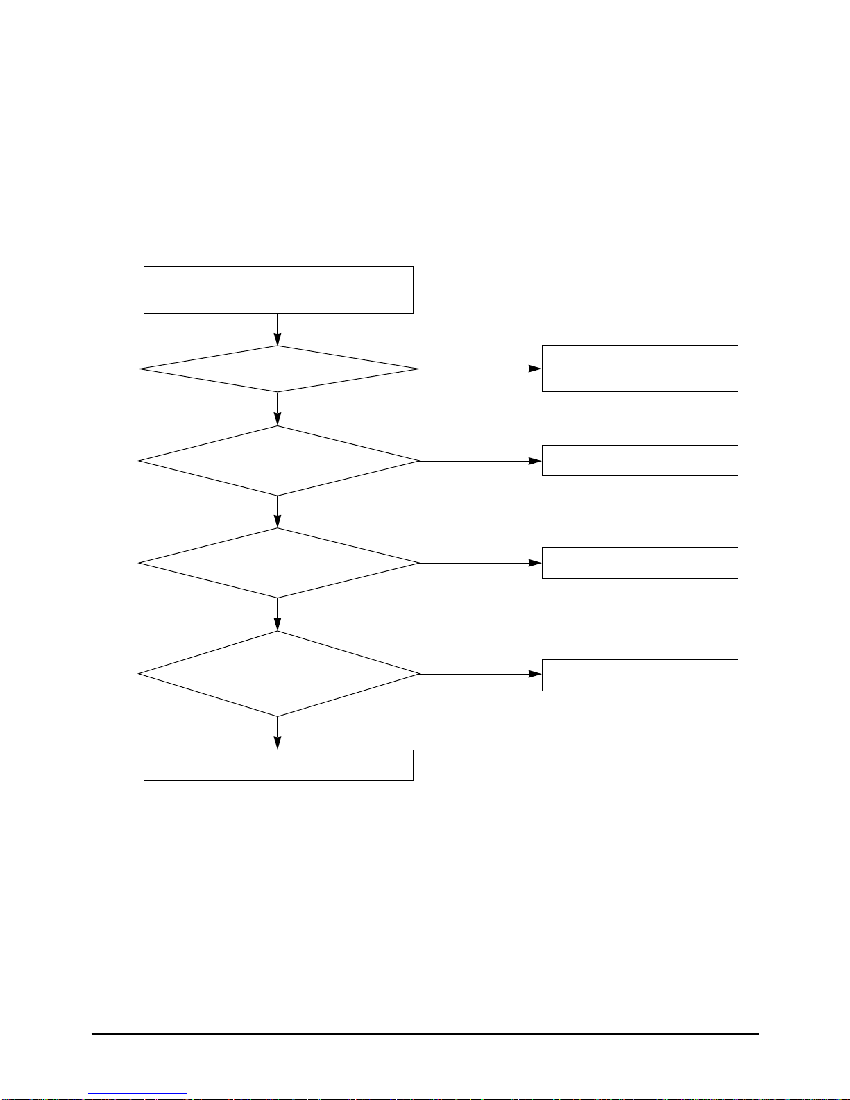
5-3-1 No Power (completely dead)-Initial diagnosis
1. Checklist :
1) Is input voltage normal?
2) Is AC power linked correctly?
3) Is input voltage of DC regulator IC KA7805 (IC02) normal? (11VDC-12.5VDC)
4) Is output voltage of DC regulator IC KA7805 (IC02) normal? (4.5VDC-5.5VDC)
2. Troubleshooting procedure
Unplug the power cord and plug it after 5 seconds
Press the Power Button on
the remote control unit to operate the air
conditioner
does not operate
◆ Check the indoor unit control board
Check whether two wires
of power cord are connected correctly to the
terminal block and control board.
Yes
Check whether the fuse on the
control board is normal.
F701: 3.15[A]/250[V]
Yes
operate
No
No
◆ Check the display board
Reconnect wires correctly
Replace fuse
Check the output of
SMPS on the control board.
Input power: AC230±15%[V]
IC02 Input: DC 12[V]
IC02 output: DC 5[V]
Yes
◆ Check the setting temperature
No
Replace the control board
Samsung Electronics20
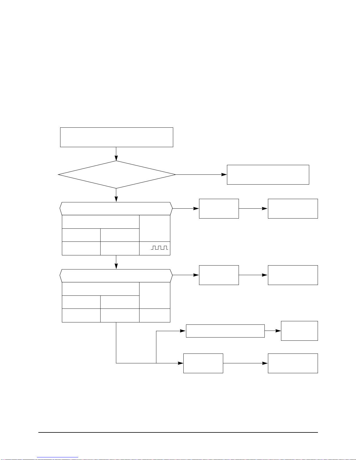
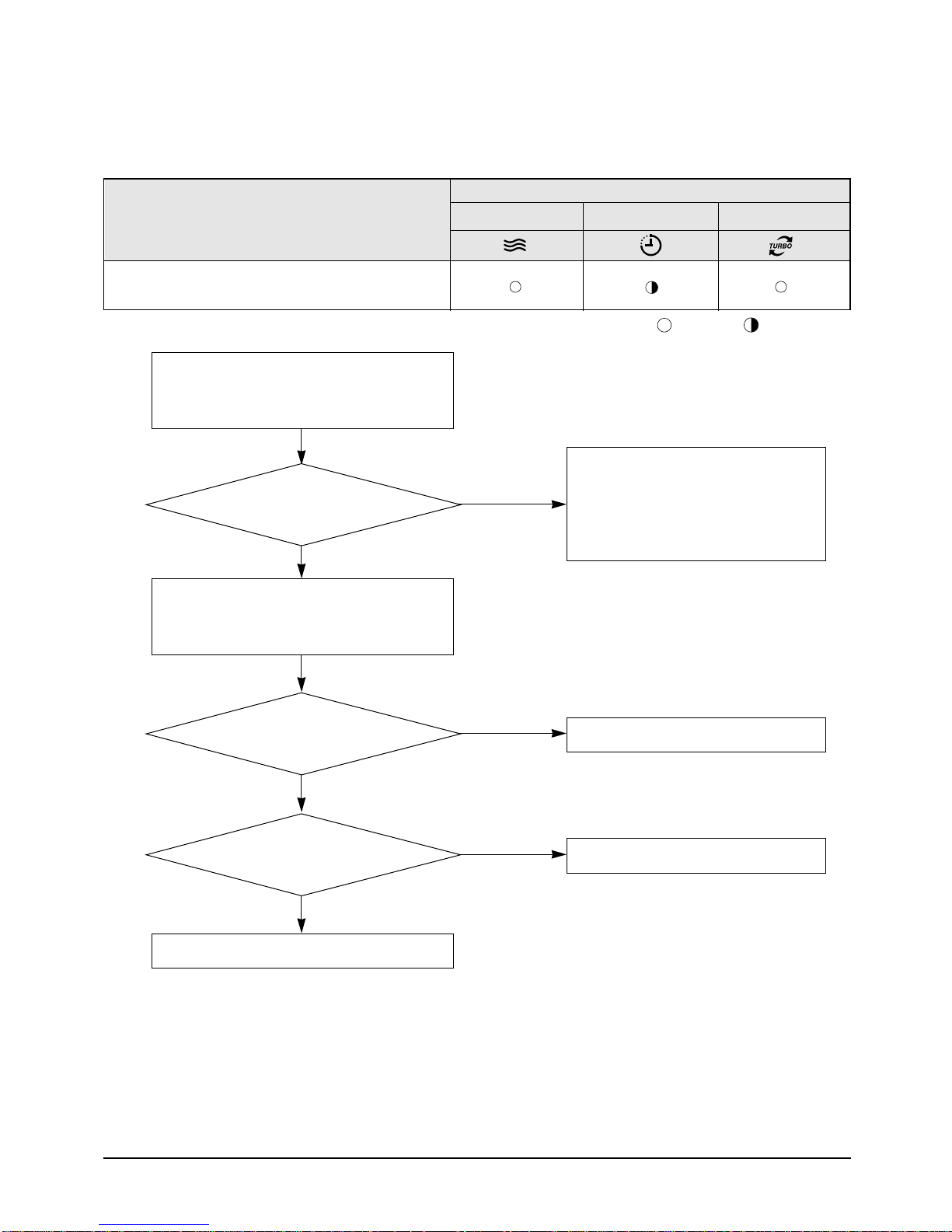
5-3-2 When the Indoor Unit Fan Does Not Operate. (Initial Diagnosis)
1. Checklist :
1) Is the indoor unit fan motor properly connected with the connector (CN72)?
2) Is the AC voltage correct?
3) Is HALL IC in indoor fan motor properly connected with the connector (CN44)?
4) Is the running capacitor (CR71) properly connected with PCB board?
2. Troubleshooting procedure
After unplugging out the power cord should
be reconnected within 5 seconds.
Yes
Troubleshooting
Does the OPERATION lamp blink?
Yes
Does the Solid State Relay(SS71) work properly?
Test rod location
+
SS71- SS71- 12V
Is the supply voltage of the fan motor sufficient?
Test rod location
PCB CN72 Condition
pin #3 and #5 Fan operate
-
Yes
Yes
Normal
Voltage
Normal
Voltage
About AC
180V
No
No
No
Motor Fan-Capacitor is out of order
Micom is
out of order.
PCB is
out of order.
Check as in the procedure
"NO power parts"
Micom
should be replaced
PCB should be
replaced.
Replace Motor
Fan-Capacitor
Fan motor
is out of order.
Fan motor
should be replaced.
21Samsung Electronics
Troubleshooting
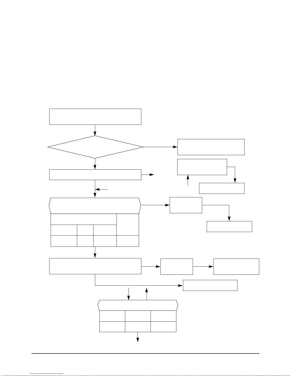
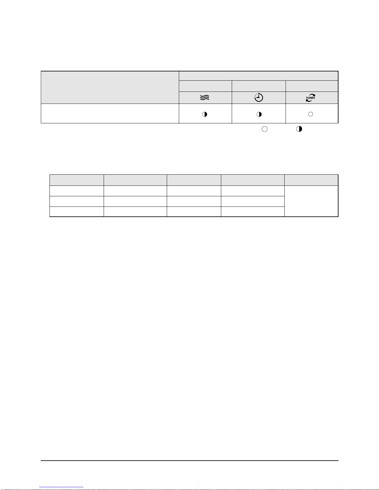
5-3-3 When the Outdoor Unit Does Not Operate. (Initial Diagnosis)
1. Checklist :
1) Is input voltage normal?
2) Is the set temperature of the remote control higher than room temperature in COOL mode?
3) Is the set temperature of the remote control lower than room temperature in HEAT mode?
4) Is the POWER IN connector (CN71) linked correctly?
5) Is the outdoor unit properly connected with the TERMINAL BLOCK connector(N(1), 1, 2, 3)?
2. Troubleshooting procedure
After unplugging out the power cord should be
reconnected within 5 seconds.
Does the OPERATION lamp blink
Yes
Does the timer lamp blink during operation?
No
#
Is the power relay RY71 operated by adjusting
the room temperature?
Test rod location
+ Condition-
Normal
Voltage
IC04 Pin No.38 RY71 ONGND DC 4.8V
Yes
Is rating voltage ±10% range applied relay between
Terminal block No. N(1) and No. 1
Yes
!
Yes
Yes
No
No
No
@
No
!
Power relay is
Check as in the procedure
"No Power parts"
Room temperature sensor is
out of order
@
PCB should be checked.
Micom is
out of order.
out of order
Outdoor unit is out of order.
PCB should be checked.
Power relay should be
replaced.
Is the room sensor normal register?
10°C20°C
30°C
12.09kΩ17.96kΩ 8.3kΩ
#
Samsung Electronics22
5-3-4 When the UP/DOWN Louver Motor Does Not Operate. (Initial Diagnosis)
1. Checklist :
1) Is input voltage normal?
2) Is the UP/DOWN louver motor properly connected with the connector (CN61)?
2. Troubleshooting procedure
Troubleshooting
Remove power cord and plug in again in approx.
5 seconds.
Is STD lamp blinking?
Yes
Does operation start when
swing button of the remote control unit
pushed?
No
Voltage at pin #57~#60
of micom (IC04) change?
(Squarewave)
Yes
Voltage at pin #16 of
IC06(ULN2003A) and #10~#12 of
IC08(ULN2003A) change?
(Squarewave)
No
Yes
No
No
Check as in the procedure
"No Power parts".
Normal
Micom (IC04) is faulty.
Driver IC06/08 (ULN2003A) is faulty.
Yes
UP/DOWN louver motor is faulty.
23Samsung Electronics
Troubleshooting
5-3-5 Room temperature sensor failure
Description
Indoor unit room temperature sensor error(open or short)
LAMP
OPERATION TIMER TURBO
Detach the assembly sensor from the
ASS'Y PCB CN43 connector and measure
the sensor resistance with an ohmmeter (tester).
Is the sensor resistance value
10KΩ ±3% at the room temperature
of 25˚C?
Yes
Connect the sensor to CN43,
supply power, and measure the voltage of
#1 and #2 of the CN43 connector.
Below 0.5V?
No
Yes
: Lamp off
ASS'Y Sensor Replace
SENSOR Resistance Value : 20˚C-12.09kΩ
SENSOR Resistance Value : 30˚C-8.31kΩ
SENSOR Resistance Value : 35˚C-6.94kΩ
SENSOR Resistance Value : 40˚C-5.83kΩ
Poor ASS'Y PCB Replace
: Lamp flickering
No
Over 4.9V?
No
MICOM Error or Connector(CN43) check
Yes
Poor ASS'Y PCB Replace
Samsung Electronics24
5-3-6 Room Pipe sensor failure
Description
Indoor unit heat exchanger temperature sensor error
(open or short)
Troubleshooting
LAMP
OPERATION TIMER TURBO
: Lamp off
: Lamp flickering
1. Check the assembly condition of the sensor connector(CN43) on the indoor unit Main PCB and if not assembled, reassemble the
connector accurately.
2. Detach the room pipe sensor connector(CN43) and check the resistance between connector 3 and 4.
Temperature(˚C)
15
20
25
Resistance Value(Kohm)
14.68
12.09
10
Temperature(˚C)
30
35
40
Resistance Value(Kohm)
8.31
6.94
5.83
Others
The data tolerance
is ±3%.
If the above data is not met, replace the room pipe sensor.
3. Assemble the room pipe sensor to PCB, plug in, and check the voltage of connector 3 and 4. If the resistance is below 0.5V or
over 4.9V, replace the indoor Main PCB. (short or disconnected in the PCB board)
5-3-7 When the remote control is not receiving.
1. Check if the connector was normally assembled.
2. Put the set in operation and check the voltage of No. 3(+) and No. 2(-) of the main PCB CN91 while operating the
remote control. When the voltage descends below 3V, the assembly module PCB is normal and the main PCB is poor.
Then replace the main PCB.
3. Replace the assembly display PCB because the module PCB is poor if the voltage between No. 2~3 of CN91
maintains 5V after the remote control starts operation.
25Samsung Electronics

5-4 PCB Inspection Method
5-4-1 Pre-inspection Notices
1. Check if you pulled out the AC power plug when you eliminate the PCB or front panel.
2. Don't hold the PCB side not impose excessive force on it to eliminate the PCB.
3. Don't pull the lead wire but hold the whole housing to connect or disconnect a connector to the PCB.
5-4-2 Inspection Procedure
1. Check connector connection and peeling of PCB or bronze coating pattern when you think the PCB is broken.
2. The PCB is composed of the 3 parts.
● Main PCB Part : MICOM and surrounding circuit, relay, room fan motor driving circuit and control circuit,
sensor driving circuit, power circuit of DC12V and DC5V, and buzzer driving circuit.
● Display part : LED lamp
● Switch part : Switch
5-4-3 Detailed Inspection Procedure
No Procedure Inspection Method Cause
1
Plug out and pull the PCB
out of the electronic box.
Check the PCB fuse.
Supply power.
2
If the operating lamp
twinkles at this time,
the above 1)~3) have
no relation.
3
Press the ON/OFF button
and operate TURBO
mode.
But, exclude the
RESERVE operation.
Press the ON/OFF button.
4
1. FAN Speed [High]
2. Continuous Operation
1) Is the fuse disconnected? (F701)
Checking the power voltage.
1) Is the DB71input voltage AC200V~AC240V?
2) Is the voltage between both terminals of the
C102 on the 2
±0.5V?
3) Is the voltage between both terminals of OUT
and GND of IC02(KA78L05) DC5V ±0.5V?
Checking the power voltage.
1) Check the voltage of the relay(RY71) coil(IC05 PIN
#11 and GND : 0V, PIN#6 and GND : 5V) during
operation(3 minutes after TURBO operation).
2) Check the voltage of both terminals of
terminal block 1 and N(1) after 3 minute
operation.: AC220V
1) Is the voltage over AC180V being imposed
on terminal #3 and #5 of the fan motor
connector(CN72)?
nd
side of the transformer AC12V
• Overcurrent
• Indoor Fan Motor Short
• AC Part Pattern Short of the MAIN PCB
• Power Cord is fault, Fuse open. Wrong
Power Cable Wiring, AC Part is faulty.
• Switching Trans or Power Circuit is faulty
• Power Circuit is faulty, Load Short
• Relay(RY71) Coil Disconnection, IC05 is
faulty
• Relay(RY71) Contact is faulty
• Fan Motor of the indoor is faulty
2) The fan motor of the indoor unit doesn't run.
3) The power voltage between terminal #3 and #5
of the connector(CN72) is 0V.
• Fan Motor Connector(CN72) is faulty
• ASS'Y Main PCB is faulty
• Connection is faulty
Samsung Electronics26
 Loading...