

Samsung S803JGB2, S803JGW2, S803JGP2, S803JGS2, S803JGE2 Service manual
WASHING MACHINE
S803JGB2/YLW
S803JGW2/YLW
S803JGP2/YLW
S803JGS2/YLW
S803JGE2/YLW
Manual
SERVICE
WASHING MACHINE
CONTENTS
Caution for the safety during servicing
1. SPECIFICATIONS
2. SAFETY DEVICES
3. OVERVIEW OF THE WASHING MACHINE
4. OVERVIEW OF THE CONTROL PANEL
5. MAIN FUNCTION
6. TECHNICAL POINT
7. GENERAL ERROR FUNCTION
8. TROUBLE DIAGNOSIS
9. TEST MODE
10. DESIGNATION OF MAIN COMPONENTS
11. PCB SCHEMATIC DIAGRAM
11-1. PCB CIRCUIT DIAGRAM
12. SETTING UP A WASH MACHINE
13. ASSEMBLE AND DISASSEMBLE
14
. TOOLS FOR DISASSEMBLY AND ASSEMBLY
15. EXPLODED VIEW AND PARTS LIST
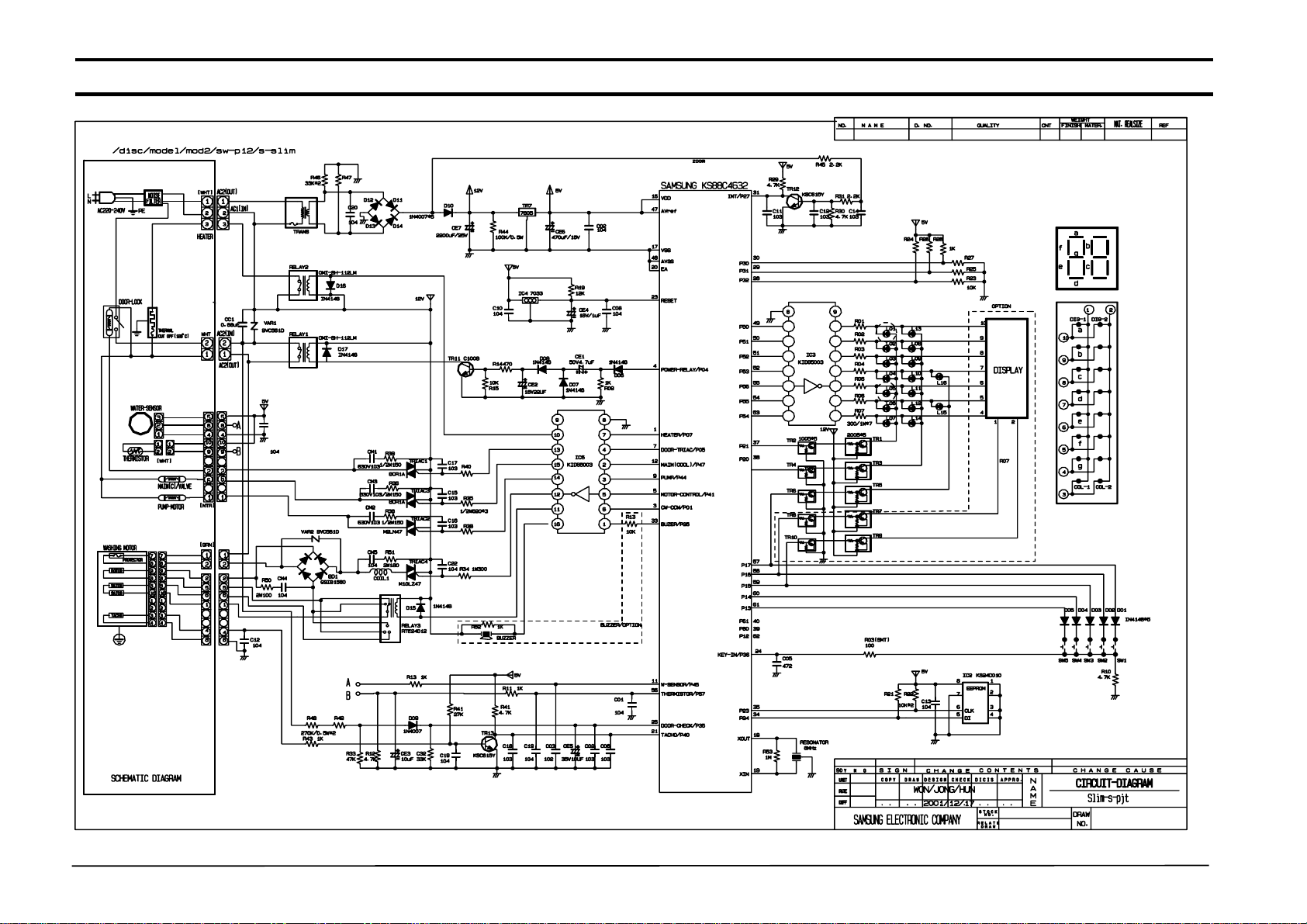
11-1. PCB CIRCUIT DIAGRAM
2
7
- 27 -
11-1. ASSY-PCB Part List
LOCATION NO. CODE NO. DESCRIPTION SPECIFICATION Q'TY REMARK
WDD01 1401-001007 THYRISTOR-TRIAC 10A,800V,20uA,300V/uS,TO-220AB 1 TRIAC1
WDD01 1401-001024 THYRISTOR-TRIAC 2A,800V,20UA,300V/US,TO-220F 1 TRIAC2
WDD01 1401-001024 THYRISTOR-TRIAC 2A,800V,20UA,300V/US,TO-220F 1 TRIAC3
WDD01 1401-001024 THYRISTOR-TRIAC 2A,800V,20UA,300V/US,TO-220F 1 TRIAC4
WDD01 1401-001024 THYRISTOR-TRIAC 2A,800V,20UA,300V/US,TO-220F 1 TRIAC5
WDD01 1401-001024 THYRISTOR-TRIAC 2A,800V,20UA,300V/US,TO-220F 1 TRIAC7
WDD02 0402-001023 DIODE-BRIDGE RBV1506,600V,15A,SIP-4 1 B/D
WDD03 3501-001180 RELAY-MINIATURE 12VDC,400mW,-,2FormC,7mS,3mS 1 RELAY3
WDD04 3501-001156 RELAY-POWER 12VDC,0.53W,16000MA,1FORMA,20MS,10MS 1 RELAY1
WDD04 3501-001156 RELAY-POWER 12VDC,0.53W,16000MA,1FORMA,20MS,10MS 1 RELAY2
WDD05 0402-000137 DIODE-RECTIFIER 1N4007,1000V,1A,DO-41,TP 1 D14
WDD05 0402-000137 DIODE-RECTIFIER 1N4007,1000V,1A,DO-41,TP 6 D15~D19
WDD06 0504-000130 TR-DIGITAL KSR1105TF,NPN,200MW,4.7K/10K,SOT-23,TP 1 TR3
WDD06 0504-000130 TR-DIGITAL KSR1105TF,NPN,200MW,4.7K/10K,SOT-23,TP 1 TR4
WDD06 0504-000159 TR-DIGITAL KSR2105,PNP,200MW,4.7K/10K,SOT-23,TP 1 TR1
WDD06 0504-000159 TR-DIGITAL KSR2105,PNP,200MW,4.7K/10K,SOT-23,TP 1 TR2
WDD07 DE13-20016A IC-VOLT REGU KA7805A,TO-220AB,1A,0/125C,-,- 1 TR7
WDD08 0501-000465 TR-SMALL SIGNAL MMBT3904,NPN,350mW,SOT-23,TP,100-300 2 TR5,TR6
WDD09 1202-000141 IC-VOLTAGE COMP. 7033,SOT-89,3P,-,SINGLE,0V,-,P 1 IC4
WDD10 2802-000188 RESONATOR-CERAMIC 8MHz,0.5%,TP,10.0x5.0x8.0mm 1 RESO
WDD11 DE13-20017A IC-DRIVE KID65003AP,DIP,16P,STICK,TR-AR 3 IC3,IC5,IC6
WDD12 1103-001203 IC-EEPROM 524C20D21,128x8Bit,DIP,8P,300MIL,-,2.5V,-,PL 1 IC2
WDD13 DE30-20016A BUZZER CBE2220BA,STICK,-,-,-,-,-,-,- 1 BZ
WDD14 3404-000282 SWITCH-TACT 12Vdc,50mA,120gf,6x6x5mm,SPST 1 SW2
WDD14 3404-000282 SWITCH-TACT 12Vdc,50mA,120gf,6x6x5mm,SPST 1 SW3
WDD14 3404-000282 SWITCH-TACT 12Vdc,50mA,120gf,6x6x5mm,SPST 1 SW4
WDD14 3404-000282 SWITCH-TACT 12Vdc,50mA,120gf,6x6x5mm,SPST 1 SW5
WDD14 3404-000282 SWITCH-TACT 12Vdc,50mA,120gf,6x6x5mm,SPST 1 SW7
WDD14 3404-000282 SWITCH-TACT 12Vdc,50mA,120gf,6x6x5mm,SPST 1 SW8
WDD15 DE07-20040A LED LAMP SLH-34VC70F,RED,T,PI5,-,-,-,- 1 L10
WDD15 DE07-20040A LED LAMP SLH-34VC70F,RED,T,PI5,-,-,-,- 1 L11
WDD15 DE07-20040A LED LAMP SLH-34VC70F,RED,T,PI5,-,-,-,- 1 L14
WDD15 DE07-20040A LED LAMP SLH-34VC70F,RED,T,PI5,-,-,-,- 1 L15
WDD15 DE07-20040A LED LAMP SLH-34VC70F,RED,T,PI5,-,-,-,- 1 L21
WDD15 DE07-20040A LED LAMP SLH-34VC70F,RED,T,PI5,-,-,-,- 1 L22
WDD15 DE07-20040A LED LAMP SLH-34VC70F,RED,T,PI5,-,-,-,- 1 L23
WDD15 DE07-20040A LED LAMP SLH-34VC70F,RED,T,PI5,-,-,-,- 1 L24
WDD15 DE07-20040A LED LAMP SLH-34VC70F,RED,T,PI5,-,-,-,- 1 L25
WDD15 DE07-20040A LED LAMP SLH-34VC70F,RED,T,PI5,-,-,-,- 1 L29
WDD15 DE07-20040A LED LAMP SLH-34VC70F,RED,T,PI5,-,-,-,- 1 L30
WDD15 DE07-20040A LED LAMP SLH-34VC70F,RED,T,PI5,-,-,-,- 1 L31
WDD15 DE07-20040A LED LAMP SLH-34VC70F,RED,T,PI5,-,-,-,- 1 L32
WDD15 DE07-20040A LED LAMP SLH-34VC70F,RED,T,PI5,-,-,-,- 1 L33
WDD15 DE07-20040A LED LAMP SLH-34VC70F,RED,T,PI5,-,-,-,- 1 L34
WDD15 DE07-20040A LED LAMP SLH-34VC70F,RED,T,PI5,-,-,-,- 1 L35
WDD15 DE07-20040A LED LAMP SLH-34VC70F,RED,T,PI5,-,-,-,- 1 L36
WDD16 DE07-00011A LED DISPLAY A4232GM-0,23.7*18.7*17.2,GRN,2dig,14seg,-,- 1 DISP
WDD18 DE34-20071A SWITCH-ROTARY DC10V,1MA,SH,PA-1005A-003-000, 1 E/SW
28
7. General Error Function
When an error occurs, this function starts to keep generating error melody sounds and displays error indicators as
l
shown in the followings per corresponding error by blinking in 0.5sec interval until the error status is completely cleared out.
In this case, all the driving devices are turned off until the error is cleared out.
1. WATER SUPPLY ERROR
- Display shows ‘ E1’ .
- Water Supply Error occurs when water level frequency does not show changes more than 100Hz or water is not supplied
up to the water level presetting for 20 min or more at the time of initial water supply.
- The error status can be cleared by turning POWER S/W OFF and resuming the POWER ON initial status.
2. WATER DRAIN ERROR
- Display shows ‘ E2’ .
- In case the water level frequency is 24.5KHz or less in the initial phase of UNB-detecting cycle.
- Water Drain error can be cleared by turning POWER S/W OFF and resuming the POWER ON initial status.
3. OVER-FLOW ERROR
- Display shows ‘ E3’ .
- Over-Flow error occurs when the water level is in abnormal operation. It can be cleared by turning POWER S/W OFF.
Water is drained prior to POWER S/W OFF and it is forced to be drained for 2 min if a frequency of more than 24.5
KHzisdetected.
4. DOOR OPEN ERROR
- Display shows ‘ door’ or‘Ed
- Door Open error can be cleared by closing the door.
5. UNBALANCE ERROR
- Display shows ‘ E4’ .
- Laundry load is unbalanced; loosen any tangled laundry.
- If only one item of clothing needs washing, such as a bathrobe or jeans, the final spin result might be unsatisfactory and an
“ E4” error message will be shown in the display window.
- Unbalance error is cleared by POWER S/W OFF and by resuming the POWER ON initial status.
6.WATERHEATERERROR
- Display shows ‘ E5,E6’ .
- In case the water temperature rises by 7°C or more in 1 min. or by 2°C less in 10 min after heating is started.
- It can be cleared by turning POWER S/W OFF.
7. ASS’ Y PRESSURE S/W ERROR
* Generated Frequency Signal of WATER LEVEL(W/L) S/W (KHz)
’
Level Low Level High Level
Abnormal W/L Frequency 30.00 KHz 15.00 KHz
- If the same signal as the above table is detected for more than 5 seconds, it is a PRESSURE S/W Error.
- When the error occurs, water drain pump will operate for 3 min. and then turn off the water drain pump.
Then the display shows ‘ E7’ indicating a pressure s/w error indicator.
8. ABNORMAL WATER TEMPERATURE ERROR
Course Water Temp
Delicate 50°C or more
Wool 50°C or more
- In case the water temperature is 50°C or more in Delicate and Wool course.
- At the time of initial water supply, if the water temperature is not appropriate, water starts to be drained
and it is forced to be drained for 2 min when the abnormal frequency of 24.5KHz is detected.
- Display shows ‘ E8’ .
- This error can be cleared by POWER S/W OFF.
9. WATER LEAKAGE ERROR (E9)
- Water Leakage error occures when water is drained naturally after washing program starts.
12

7. General Error Function
10. Tacho Error
- This error occurs in case motor thaco is out of order or tacho siganals inputted are fewer than 2
- "EA" displayed
- This error can be cleared by power s/w off
11. Motor Triac short Error
- This error occurs in case over 300 per 1 sec tacho signals are inputted power S/w should be off.
- "Eb" displayed.
- This error can be cleared by power s/w off
12. Thermistor error
- This error occurs, when Thermistor circuit is abnormal or the detected electrical volt is 0.2v below or 4.5v over
- "Ec" displayed
- This error can be cleared by power s/w off
13
8. Trouble Diagnosis
- As the micom wash machine is configured of the complicate structure, there might be the service call.
Below information is prepared for exact trouble diagnosis and suitable repair guide.
Caution for the Repair and Replacement
Please follow below instruction for the trouble diagnosis and parts replacement.
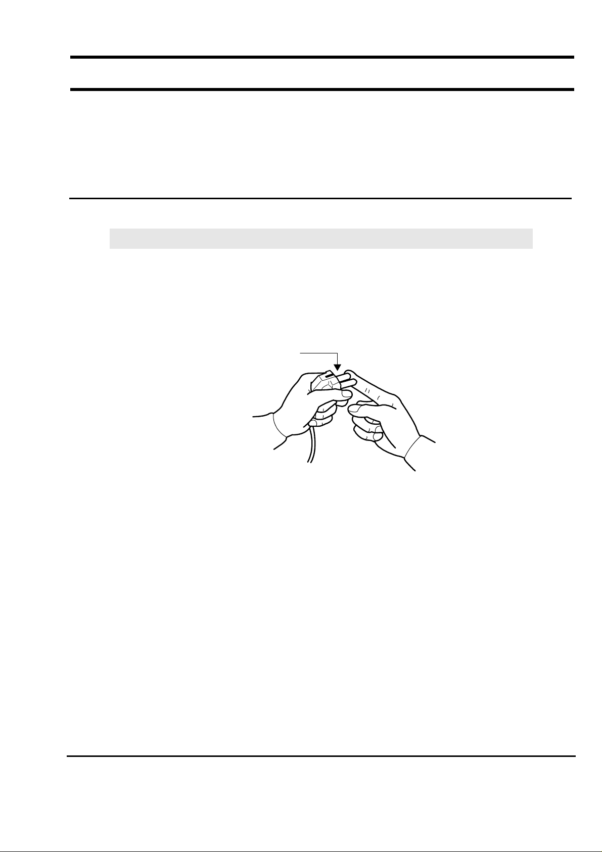
1) As some electronic components are damaged by the charged static electricity from the resin part of wash
machine or the human body, prepare the human body earth or remove the potential difference of the
human body and wash machine by contacting the power supply plug when the work contacting to PCB is
executed.
POWER SUPPLY PLUG
2) Since AC220~240V is applied to the triac T1 and T2 on P.C.B, the electric shock may occur by touching
and be careful that the strong and weak electricity are mixed.
3) As the P.C.B assembly is designed for no trouble, do not replace the P.C.B assembly by the wrong
diagnosis and follow the procedure of the trouble diagnosis when the micom is not operated normally.
14
8-1. Trouble Diagnosis
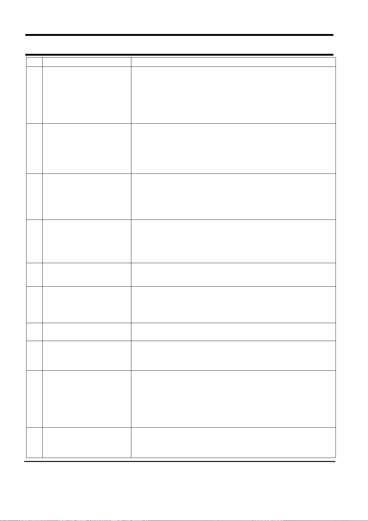
No Item Cause and treatment
- Is the PCB connector connected well?
- Is the voltage normal?
- Is the power supply plug connected well?
1 The power is not supplied
2 The water is not supplied.
The wash does not start though
3
the water supply is stopped.
- Is the noise filter connected well?
- Is the secondary output of the power supply transformation normal?
- Is the fuse disconnected? (option)
• If above points are not found, the PCB assembly is out of order.
Replace it.
- Is the knob open?
- Did you push START/PAUSE button after selecting the course?
- Is the water supply valve connected well?
- Is the winding of the water supply valve continuous?
- Is the connection and operation of the pressure switch normal?
• If above points are not found, the PCB assembly is out of order.
Replace it.
- Is the connection and operation of the pressure switch normal?
- Is the pressure switch hose damaged so that the air is leaked?
- Is the pressure switch hose bent?
- Check the operation of the water level switch.
• If above points are not found, the PCB assembly is out of order.
Replace it.
The drum does not rotate during
4
washing.
The drum rotates by one direction
5
during washing. (The drum rotates
to one direction for SPIN.)
6 Drainage problem.
7 Dehydration problem.
8 Abnormal noise during SPIN.
Leak breaker or current/leak
9
breaker is down during washing.
10 The heating is not executed.
- Is the belt connected well?
- Is the winding of the motor continuous?
(Rotor winding, stator winding, generator)
- Is the motor protector normal?
• If above points are not found, the PCB assembly is out of order.
Replace it.
- The PCB assembly is out of order. Replace it.
(Inversion relay open trouble)
- Is the drainage hose bent?
- Is the winding of the drainage pump continuous?
- Is the drain filter clogged by the waste?
• If above points are not found, the PCB assembly is out of order.
Replace it.
- The unbalance is detected.
- Put in the laundry uniformly and start again.
- Is the pulley nut loosen?
- Is the transport safety device removed?
- Is the product installed on the level and stable place?
(Little noise may be generated during the high-speed SPIN.)
<When the leak breaker and current breaker is installed separately>
- When the leak breaker is down, check and make the earth of the outlet.
- When the current is down, the current is leaked.
<Is the breaker down when the leak/current breaker is combined?>
- Check the rated capacity of the current and leak breaker.
The current breaker may be down due to the lack of the current when the
wash machine and other apparatus are used.
In this case, execute the cold water wash to check whether the current capacity is lack.
- Is the wash heater terminal unplugged?
- Is the wash heater normal?
- If above points are not found, the PCB assembly is out of order.
Replace it.
15
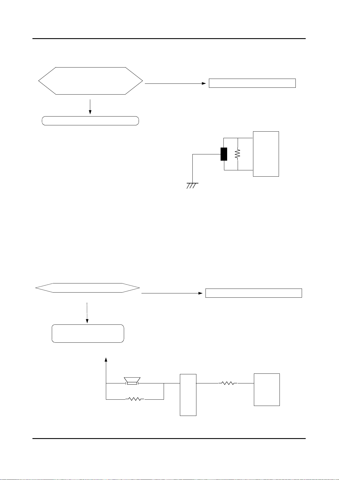
8-2 . Problem Checking And Method Of PCB
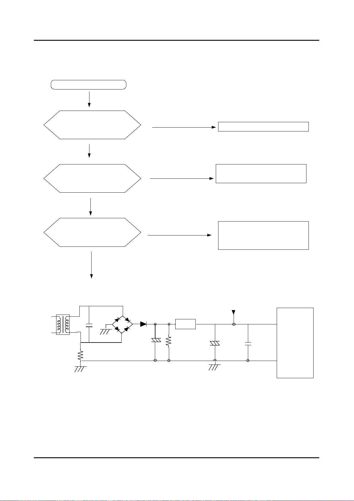
8-2-1 The Part Of Power Source
NO Power On
YES
The Voltage Of
BetweenⓐandⓑIs
As Big As 12V?
YES
NO
Check The Trans
TRANS
The Voltage Of
Betweenⓒand
As Big As 12V?
YES
The Voltage Of
Betweenⓔand
As Big As 5V?
YES
ⓐ
ⓑ
ⓓ
Is
ⓓ
Is
D15,16,18,19
2200UF
D17
ⓒ
NO
NO
TR7
7805
Check The Diode(D15-D19)
And Condenser(CE5)
Exchange TR7(7805) And
Check The
Condenser(CE3)
CE3
470UF
ⓔ
60
61
62
CE5
30
63
ⓓ
16
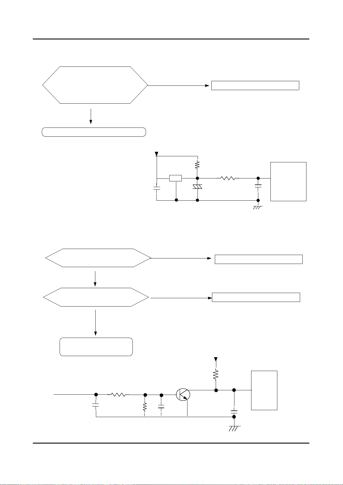
8-2-2. Reset Part
The Value Of
Measurement Result Of
Between Micom 26 And
Check IC3
Is 5V?
YES
NO
IC3
7042
Check The Power Source
R12 100
26
CE1 1UF
8-2-3. Interrupt Part
Check The Curve
Output Ofⓐ?
Check The Micom
Number 11 ?
Check The Part Of
Oscillator
ⓐ
R64 2.2K
Check D15 - D19
Check TR6, R60
R60 4.7K
TR6 815
11
R61 C23
C22
17
8-2-4. Checking The Part Of An Oscillator
When The Micom 27,28
Check, The Value Is
8Mhz?
YES
Exchange Micom And Check R29
NO
Check Resonator
8-2-5. Check The Part Of Buzzer
ⓐ
Part Confirm DC12V ?
NO
R29 1M
27
28
RESO
8MHz
Check The Part Of Power Source
YES
Exchange BZ,
Check R40,R13
12V
ⓐ
BZ
R40 1K
IC6
R13 10K
12
ⓑ
18
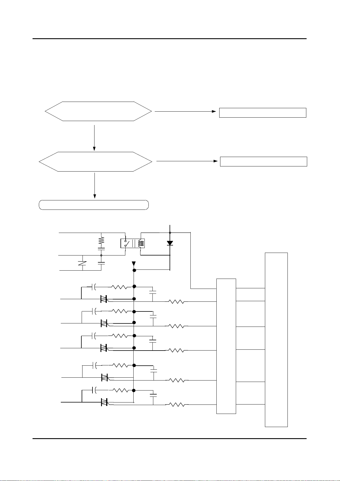
8-2-6. Driving Part Checking
◆◆◆◆
Confirm The Output Of DC5V, When The Every Part Of Micom Number Check,
According To The Some Problem Condition
ex) When The Drain Is Not Operating But Pump Motor Is Operating, Check
The 5Voltage Of Micom
Micom Number, 17 Is
5Voltage?
YES
The Part Of
ⓐ
Is
0 Voltage?
YES
Check R48, TRIAC4
NO
Micom Bad
NO
Check The IC 65003
MICOM
IC65003
ⓐ
TRIAC5
TRIAC3
TRIAC2
TRIAC7
TRIAC4
※※※※
Check The Micom 18th In The Above Method When The Cold Water Is Bad
R54
R47
R58
R51
R48
ⓐ
ⓐ
ⓐ
ⓐ
ⓐ
POWER
PRE
COLD
RINSE
DOOR
PUMP
37
19
18
38
16
17
19
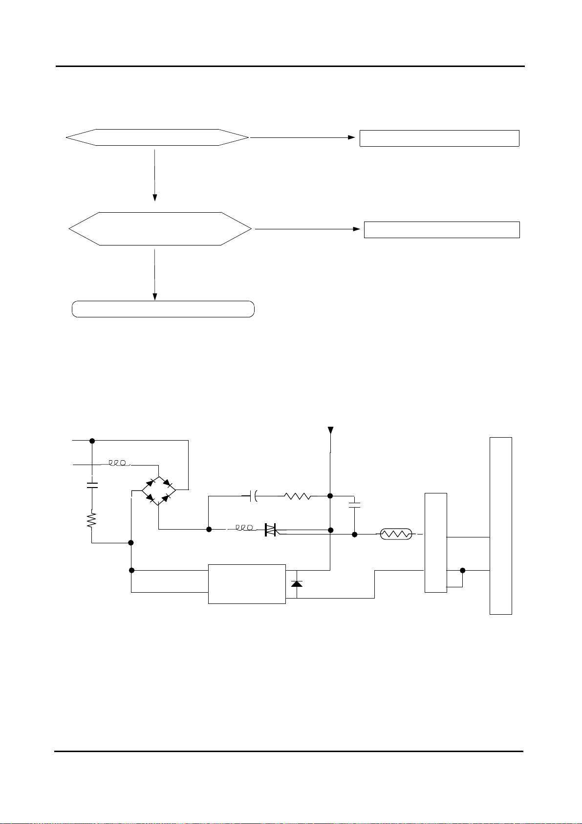
8-2-7. Confirm The Driving Part Of Motor
Motor Is Not Spinning
NO
Motor Is Not Turning
Right And Left
NO
Check The Tacho Part
YES
Check BD1, TRIAC1
YES
Check RELAY2
CM05
R69
BD1
COIL2
RELAY3
CM2
R71
TRIAC1
12V
MICOM
IC 65003
R46
22
1W 300
15
D13
20
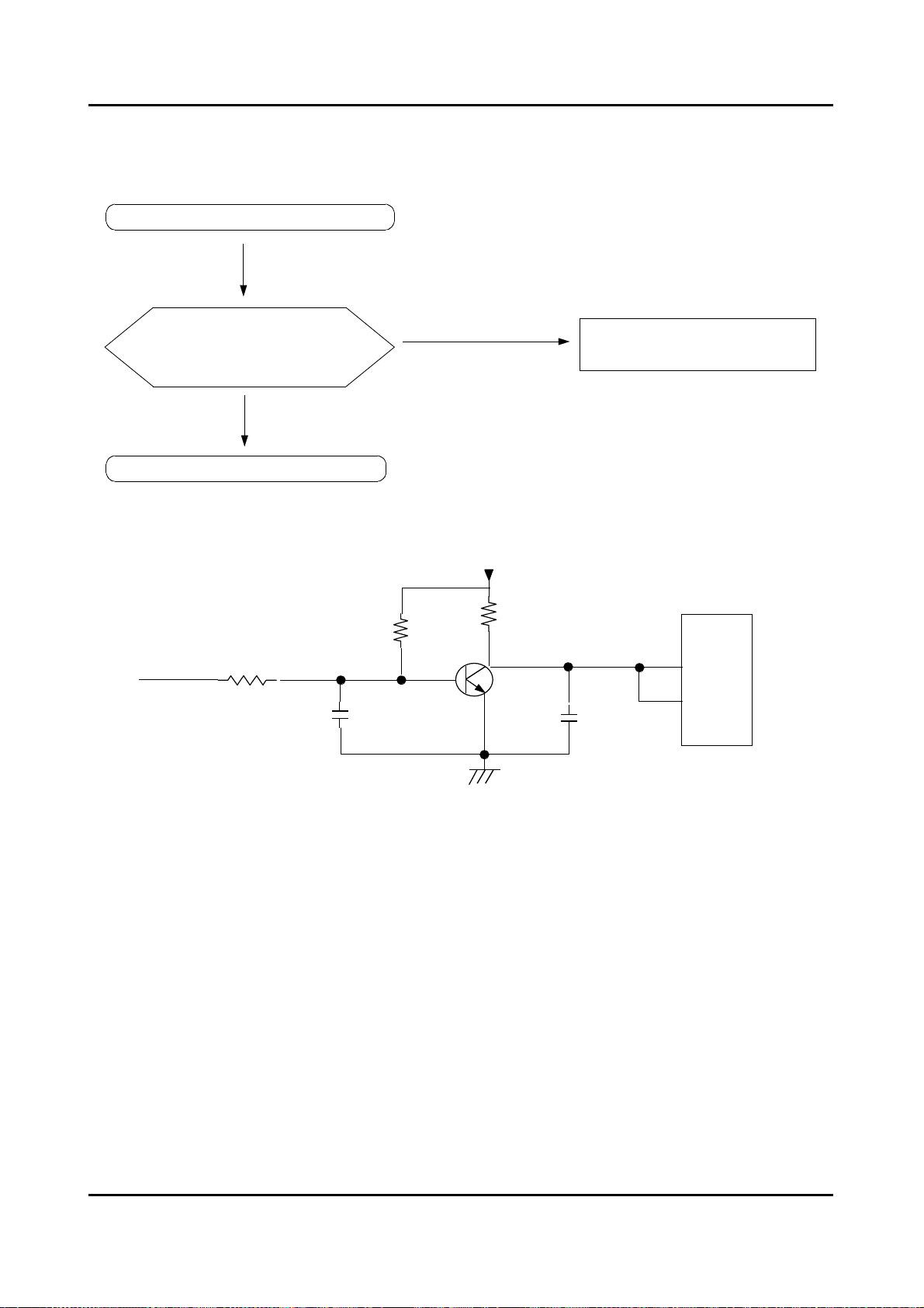
8-2-8. Checking The Tacho Part
Have The Motor Turn In Hand
Is The Rectangular
CurveInTheMicom8,
10th ?
YES
Exchange The Motor
R38 1K
R39
C15
TR5
NO
R41 4.7K
815
Check The Surroundings
Circuit And TR5
MICOM
8
10
C28
21
 Loading...