

Page 1

Notice
1998. All rights reserved
The information within this manual is subject to change without notice.
The manufacturer sh all not be held liable for technical or editorial errors or
omissions conta ined herei n; nor for incidental or con sequential damages result ing
from the furnishing, performance or use of this material.
No part of this publication may be reproduced, sto r ed in a retrieval system, or
transmitte d, in any form or by any means, mechanical photocop ying, recording or
otherwise, without the prior written permission of the manufacturer.
Product names mentio ned herei n are for ident ifica tio n purposes onl y , and may be
trademarks and / o r registe red trademarks of their respective co mpanies.
This product incorporates copyright protection technology that is protected by
method claims of certain U.S. patents and other intellectual property rights
owned by Macrovision Corporation and other rights owners.
Use of this copyright protection technology must by autho r ized by Macrovision
Corporation, and is int ended for home and ot her limit ed vi ewing uses only unles s
otherwise authorized by Macrovision Corporation. Reverse e ngineering or
disassembly is prohi bited .
i
Page 2

Important Safety Instruction
Read all of these instructions, and save these instructions for later use.
•Follow all warnings and instructions marked on the product.
•Unplug th is product from the wall outlet before cleaning. Do not use liquid
cleaner s o r aer osol cleane r s . Us e a damp cloth for cl ean i n g .
•Do not use this product near water. Never spill liqu id of any kind on the
product.
•Do not place thi s product on an unstable cart, stand, or table.
•Slots and openings in the cabinet are provided for ventilation. To ensure
reliable operat ion of the product on a bed, sofa, rug, or other simi lar
surface. This produc t should never be placed near or over a radiator or
heat register. This product should not be pl aced in a built-in inst allation
unless proper vent ilation is provide d.
•Before connecting this product to a power so urce, check the required
voltage and frequency match the available power source.
•This comput er is powered by an interna l battery pack or by an external AC
power source, Which is supplied with the computer. Use of another
battery pack or AC power source may present risk of fi re or explosion. To
disconnect the AC power cord and remove the battery packs .
•This produ ct is equip ped with a 2-wi re type pl ug. I f you are unab le to ins ert
the plug into the outlet, contact your el ec trician to replace your obs olete
outlet.
•Do not allow anything to rest on the power cord.
•Do not place this product in a location where someone may trip over the
cord.
•If an extensi on cord is used with this prod uct, mak e sure tha t the tot al of the
ampere ratings on the products plugged into the extension cord do not
exceed the exte nsion cord ampere rating. Also, make sure that the total of
all products plugged into the wall outlet does not exceed 15 amperes.
•Never push objects of any kind into th is product through the cabinet slots,
as they may touch dangerous voltage points or short out parts; that could
result in a risk of fire or electric shock.
•Except as e xplain ed els ewhere i n thi s manual, do not att empt t o servi ce this
product yourself.
•Handle battery with care. If dropped, they may damaged.
•Do not allow the bat tery to be exposed to direct sunl ight for extended
periods of time.
ii
Page 3

•Do not attempt to disassemble the battery. If the battery is disassembled and
the electro des are exposed to outside, the battery may generate eat and
smoke by chemical reac tion.
•Do not expose the battery to moisture or chemicals.
•Charge the battery only as described in this document.
•Do not short circuit the battery terminals as the resulting high currents can
damage the battery.
•The battery s hould not be used to power other products.
•Do not di spose of a us ed bat ter y in a fire or inc inerat or , as a n explo sion m ay
result.
•The battery s hould be recycled.
•Do not subjec t the battery to temper ature should not less than -20 degrees
Centigrade or greater than 50 degrees Centigrade.
•Unplug this product from the wall outlet and refer problems to the service
representative under the following conditions:
- When the power cord or plug is damaged or frayed.
- If liquid has been spilled into product.
- If the product has been exposed to rain or water.
- If the product does not operate normally when the opera ting
instructions are followed, adjust only those controls that are
covered by the operating instructions. Improper adjustment of
other controls may result in damage.
- If the product exhibits a distinct change in performance.
iii
Page 4

Federal Communications Commission
(FCC)
This device complies with Part 15 of the FCC Rules. Operation is subject to the
following two conditions:(1) this devic e may not cause harmful interfe rence, and
(2) this device must accept any interference received, including interference that
may cause undesired operation.
NOTE:
This equipment has been tested and found to comply with the limits for a Class B
digital device pursuant to Part 15 of th e FCC Rules. These limits are designed to
provide reasonable protection against harmful interference in a residential
installati on. This equ ipmen t gener ate us es and c an radi ate ra dio fre quen cy ener gy
and if not installed and used in accordance with the instructions may cause
harmful interference will not occur in a particular installation. If this equipment
does cause harmful interference to radio or television reception, which can be
determined by turning the equipment off and on, the user is encouraged to try to
correct the interference by one or more of the following measures:
•Reorient or relocate the receiving antenna.
•Increase the separation between the equipm ent and receiver.
•Connect the equipment into an outle t on a circuit different from that to
which the receiver is connected.
•Consult the dealer or an experienced radio/TV technician for help.
If necessa ry, the user shoul d consult the d ealer or an experienced radio/t elevision
technicia n for additional suggestions. The user may find the following booklet
helpful: "Something About Interference." This is available at FCC local regional
offices. Our company is not responsible for any radio or television interference
caused by unauthorized modifications of this equipment or the substitution or
attachment of connecting cables and equipment other than those spe cified by our
company. The correction will be the responsibility of the user. Use only shielded
data cables with this system.
v
Page 5

Canadian Radio Interference
Regulations
This apparat us doe s not exceed th e c lass B limi ts for radio noi se e missi ons set out
in the radio interference regulations of the Canadian Department of
Communications.
Le présent appareil n’émet pas de bruits radioé lectriques dépassant les limites
applic ab le aux appa re ils de la clas s e B p r escrites p ar le règlem en t d e br o u i ll ag e
radioélectrique dicté par le Ministère des Communictions du Canada.
vi
Page 6
Introducing Your Computer
Your computer is a lightweight portable compute r that includes features to meet
your computing needs at home or on the r oad.
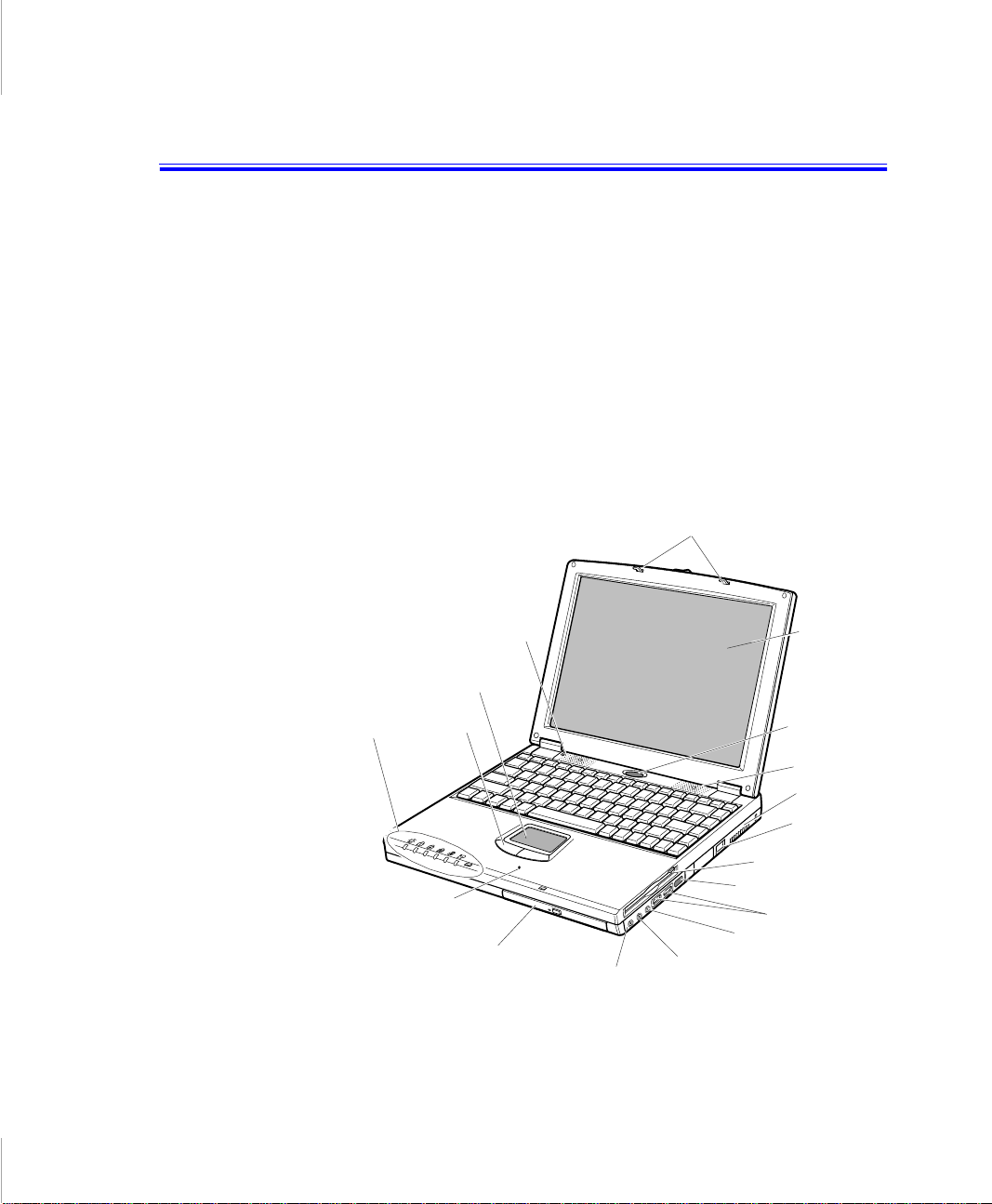
Your computer is one of 3-spindle type computer and 2-s pindle type computer.
These computers are basically same, but the device arrangement is different.
• 3-spindle type computer has CD-ROM drive and floppy drive within the
computer.
• 2-spindle type computer has CD-ROM drive and external floppy dis k drive
with its c onnectable cable. And different Status lights posit ion from 3-spindle
type computer.
Figure 1 through 4 show you the featur es of your computer.
Cover latch
Speaker
Touchpad
Status
lights
Mouse
Buttons
Microphone
CD-ROM drive
Line-in
Floppy drive
Infrared port
External-mic jack
Headph one
jack
Figure 1. Front View of Computer (3-spindle type computer)
Introducing Your Computer 3
LCD
Power button
Speaker
Fan vent
Modem jack
USB ports
Page 7
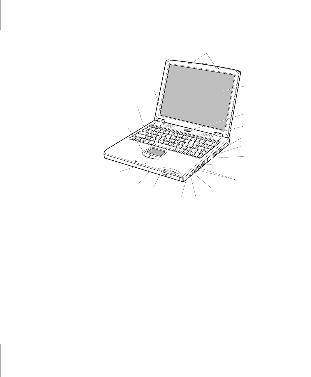
Cover latch
Speaker
Touchpad
Mouse
Buttons
Infrared port
Microphone
CD-ROM drive
Status
lights
Line-in
External-mic jack
Headphone
jack
USB ports
Figure 2. Front View of Computer (2-spindle type computer)
LCD
Power button
Speaker
Fan vent
Modem jack
External
Floppy
Connec tors
4 User’s Manual
Page 8
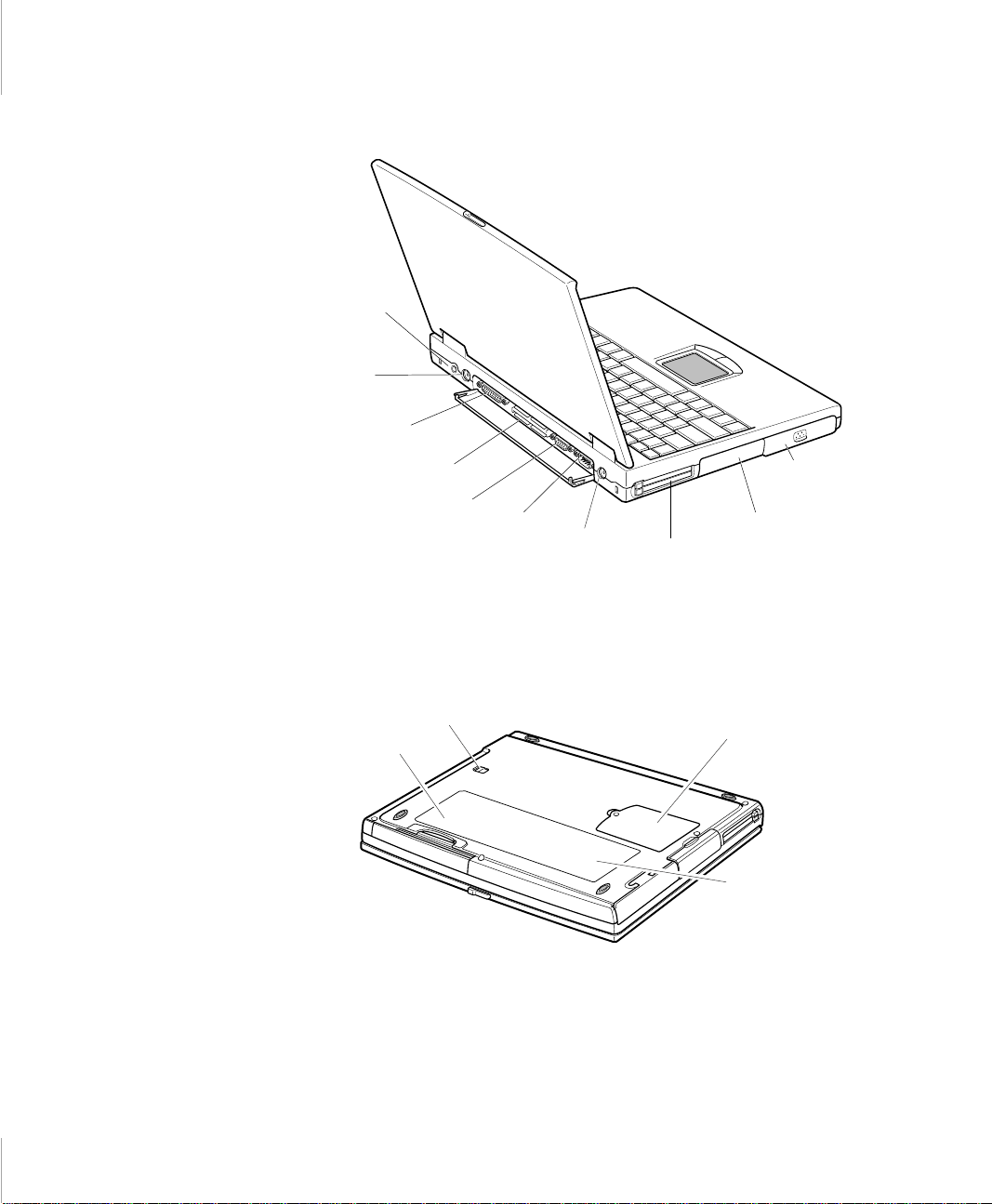
Power Connector
PS/2™
mouse and
keyboard
port
Parallel port
Docking
connector
Video port
Serial
port
TV out
Figure 3. Back View of Computer
PC Card
compartment
Battery
compartment
Hard dr ive
compartment
Drive bay latch
Business card holder
Figure 4. Bottom View of Computer
Memory module
compartment
Label showing
part number and
seri al number
Introducing Your Computer 5
Page 9
Using Your Computer for the First Time
This section gives you det ailed information on using your co mpu ter for the first
time.
Installing the Battery
Your computer comes wit h the batte ry pack separate from the comput er. To insta ll
the battery pack:
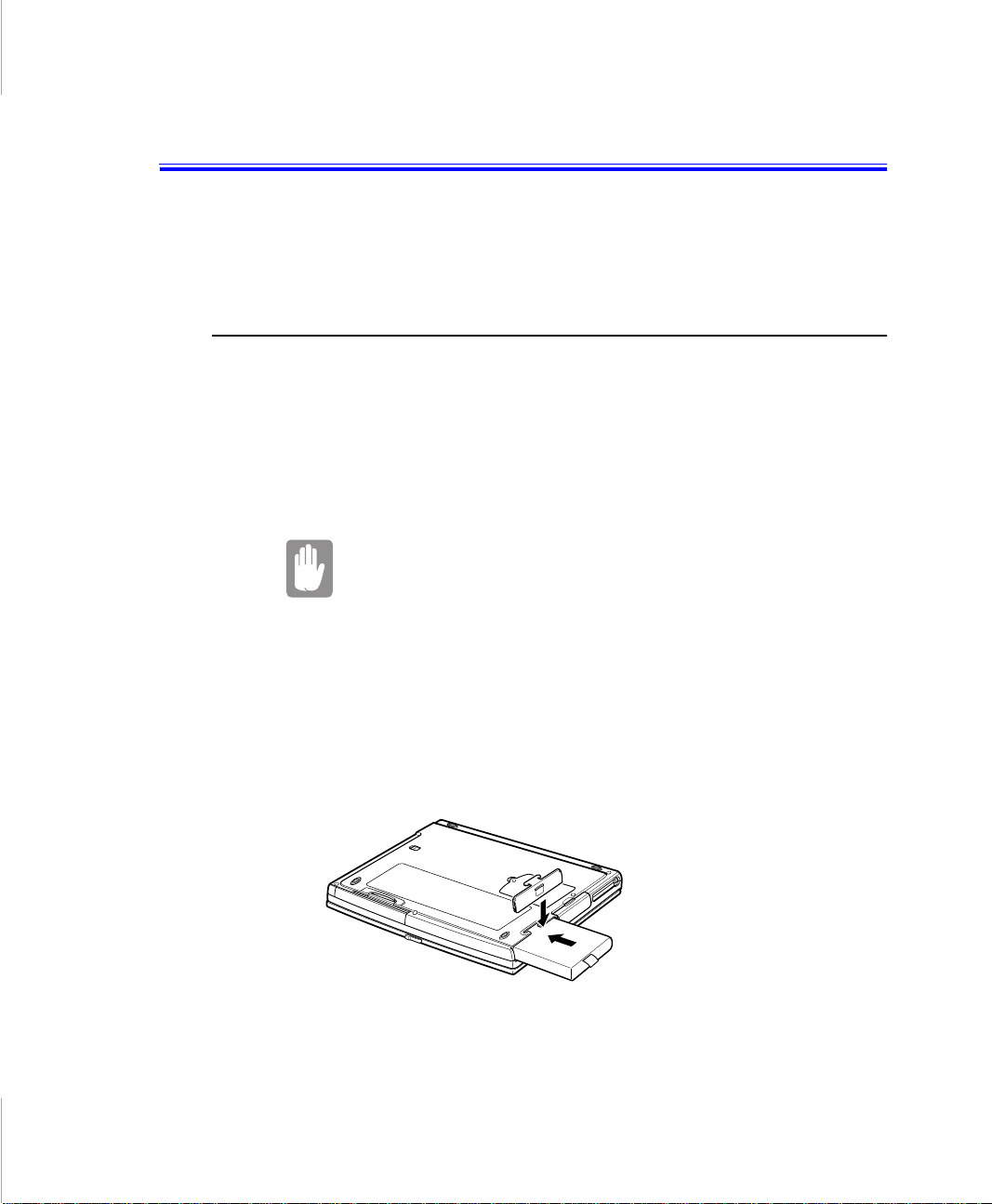
1. With the computer’s power off, close the LCD panel and turn the computer
over so the bottom of the unit faces up.
2. Sl ide the battery compartment cover straight up and off th e computer(Figure
5).
Insert the battery into the battery compartment in right
direction or the battery does not fit on its slot properly.
3. Slide the batter y pack into the compartment. Make sure the battery is fully
inserted into th e co mpartment.
6 User’s Manual
4. Align the tabs on the battery compartment cover with the slots on the battery
compartment.
5. Push the cover straight down until it snaps into place.
Figure 5. Installing the Battery
Page 10
Attaching the Power Cord
Your computer runs on power from the battery in the computer or from an
electrical out let. The firs t time that you use your c omputer, fully c harge the batt ery
by attaching the power cord to the computer and to an electrical outl et.
All batteries lose their charge if they sit unused for an
extended time period. When not used, battery can discharge
fully in 2 to 3 months. The battery may have discharged in the
time it took for the computer to go from the factory to you.
To attach th e power cor d :
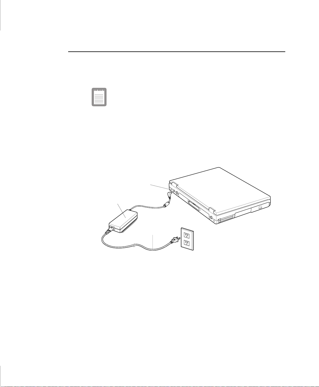
1. Pl ug the AC adapter into the power connector on the back si de of the computer
(Figure 6).
2. Connect the power cord to the AC adapter and then to an electrical outlet.
Power connector
AC Adapter
Power cord
Figure 6. Connecting the Power Cord
The battery starts charging as soon as you plug the power cord into an electrical
outlet. The battery charges faster if the computer is turned off during charging.
If the battery is fully depleted and the computer is turned off, the battery charges
in about 3 h ours . If the com puter i s t urne d on, the batt ery charge s i n about 5 hour s.
When the battery is charging, the battery charge light is amber. When the battery
is fully char ged, the light turns green.
See ”Using the Batter y” on page 35 for more information on us ing your
computer’s batt ery.
Using Your Computer for the First Time 7
Page 11
Turning On the Computer
To turn on the computer’s power for the first time:
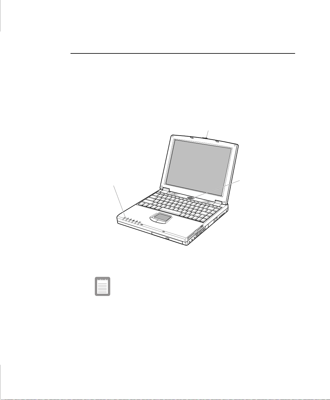
1. Push to the right and hold the cover latches on the front of the cover.
2. Lift up the cover.
3. Pre ss and then release the power button (Figure 7).
The power light is on when the computer’s power is on.
Cover latch
Power light
Power button
Figure 7. Turning On the Computer’s Power
The front view of the computer might differ from 3-spindle
type computer to 2-spindle type computer.
8 User’s Manual
Page 12

Understanding POST
When you turn on your computer, a routine cal led POST (Power-On Self-Test)
automatically runs to test the computer components. Several messages appear on
the screen during POST.
Screen messages are built into the computer to report both normal and abnormal
system conditions. If an error message appears, take any action suggested in the
message. If the message identifies the error condition but does not suggest any
corrective action, write down the message and contact the manufacturer or an
authorized reseller’s service center for assistance.
Adjusting the LCD Display
You may wish to adjust the LCD (Liquid-Crystal Display) when you begin using
your computer. A TFT (Thin-Film Transistor) LCD does not require adjustm ent
for contrast because the contrast is set to remain a t maxim um.
To adjust the LCD:
• Press <Fn+Right Arrow> to increase the display brightness.
• Press <Fn+Left Arrow> to decrease the display brightness.
Making Backup Disks
Use the Create System Disks Utility in Windows 98 to make b ac kup disks of any
software on your hard driv e. The util ity will st art automat ically when you us e your
computer for the fir st tim e. You can also open the utility by doing the following:
1. Click the Start button on the taskbar.
2. Select Programs.
3. Select Accessories.
4. Select System Tool s.
5. Click Backup.
Using Your Computer for the First Time 9
Page 13
Turning Off Your Computer
If your computer has a Windows operating system, turn off
your comp uter by performing the shu td own procedure
described in this section. Otherwise, you may lose data.
To turn off the computer:
1. Click Start on the taskbar.
2. Click Shut Down.
3. Select the shut down option.
4. Click OK or Yes.
• If the operatin g system is Windows 98, the computer turns off.
• If the operating system is Windows NT, you receive a shutdown message
and must press the power button to turn off the computer.
• Under the ACPI mode, you can shut down the computer or enter the
standby mode by just pressing the power button.
Restarting Your Computer
10 User’s Manual
You may need to restart (reboot) your computer when installing hardwa re or
software or if the computer does not respond to your input. A warm (or s oft) boot
prompts you to save your files, turns off the computer, and the n res tarts the
computer. A cold boot turns off the computer without saving your files.
To perform a warm (or soft) boot:
1. Click Start on the taskbar.
2. Click Shut Down.
3. Select the restart option.
4. Click OK or Yes.
5. Save your files if prompted. Your computer reboots.
Page 14

Do not perform a c ol d bo ot un less your keyboard and
touchpad have no effect and you cannot perform a warm
boot.
When you perform a cold boot, you lose data unless it was
saved to a storage medium.
You can also perform a soft boot by saving your files and pressing
<Ctrl+Alt+Del>. You can perform a cold(or hard) boot by pressing the power
button to turn the computer off, waiting five second, and then pressing the power
button to turn the com puter on.
Tips for Using Yo ur Computer
The following information helps you avoid potential problems as you use your
computer:
Do not try to disassemble your computer. Opening the
system chassis voids your warranty. Only an authorized
manufacturer’s service center can replace or add any parts
inside the chassis.
• Follow all the instructions and c autions in your computer user documentation.
• The LCD has a polarized sur f ac e and can be damaged easily. To preven t
damage, avoid touching the screen.
• Use only memory modules which provided from authoriz ed s ervice center.
• Because a notebook computer is small and has restricted air flow around
components, it is more likely to overheat than a desktop computer. A fan
inside your co mputer runs when needed to help e liminate some heat. Make
sure the fan vent on the right side of your computer is not blocked when you
use the computer . (See Figure 1 for the location of the ve nt.) Occasionally
check the vents and remove any accumulated dust on the outside.
• Avoid using or storing the computer in extremely hot or cold areas, such as a
car on a hot day. Keep the computer away from heaters and out of direct
sunlight. Exposure to excessive heat may damage computer components.
Usin g Your Co mputer for the First Time 11
Page 15

If you have left your computer in a hot place, let it cool down slowly to room
temperature (with the LCD panel open) before using it.
• Do not remove the memory-modul e compartment door, or try to in st all a
memory module when the computer is on. (See ”Bottom View of Computer”
on page 5 for the location of the door.)
(For information on installing memory modules, see “Installing a Memory
Module” on page 74.)
• Set up your computer work area to avoid physical strain. Sit with your back
straight and supported by your chair. Adjust your chair or work table so that
your arms and wrist s can remain in a relaxed positio n, parallel with the floor.
Avoid bending or twis ting y our wri sts as you work. Yo ur ha nds shoul d “fl oat”
slightly above the keyboard. Refer to a book on office ergonomics for more
information on setting up your work area.
• Take frequent breaks from working at the computer to rest your eyes and
stretch your muscles.
• Remember to save your data files frequently and to make backup copies of
your files.
Traveling with Your Computer
If you are traveling by airplane, follow these tips:
• Take the computer with you as carry-on luggage. Do not check the computer
with your baggage .
• Allow the computer an d dis ks to go through the X-ray security devices. Do
not hand-carry di sks through the walk-through metal detectors, which can
cause loss of d at a.
• Mak e su r e th at th e b a t te r y is charged or th e po w er cord is ea s il y acc es sible.
You may be required to turn on the computer for airport security personnel.
• Be prepared to turn off the computer during take off and landing.
Handling Sp ills
Do not spill anythi ng on your computer. The best way to avoid spi lls is to avoid
eating and drinki ng around your computer. If you do spill something on your
computer, turn off your computer, unplug it immediately, and do the following:
12 User’s Manual
Page 16
• If you spill liquid on the keyboard, drain as much of the liquid from the
keyboard as pos sible. Be carefu l not to let the liquid drip onto the LCD panel.
Allow the system to dry for s everal days before trying to use it.
• If you spill liqui d on an ex ternal keyboard or keypad, unplug it and drain as
much of the liquid as possible. Allow the ke yboard to sit at room tempera ture
for a full day before trying to use it.
Sweet liquids leave a sticky residue that may jam the
keyboard despite your efforts to dry it.
• If you spill li qui d on the LC D panel, clean it immedi atel y with a soft c loth and
denatured al cohol. Do not use water, window clea ner, acetone, aromatic
solvent, or dry, rough towels to clean it.
Some liquids damage the polarized LCD screen. If your
screen is damaged, contact your authorized manufacturer’s
service center for a replacement.
Storing the Computer for Long Periods
If possi ble, l eave the pow er co rd conn ected t o th e comput er an d an el ectri cal ou tlet
when the computer is not in use. This extends the l ife of the battery and keeps the
battery fully char ged.
If you will not be using the computer for a long period of time (a mont h or more),
you should charge the bat tery until it is comple tely full. After you have done so,
remove the batt er y from the unit.
Usin g Your Co mputer for the First Time 13
Page 17
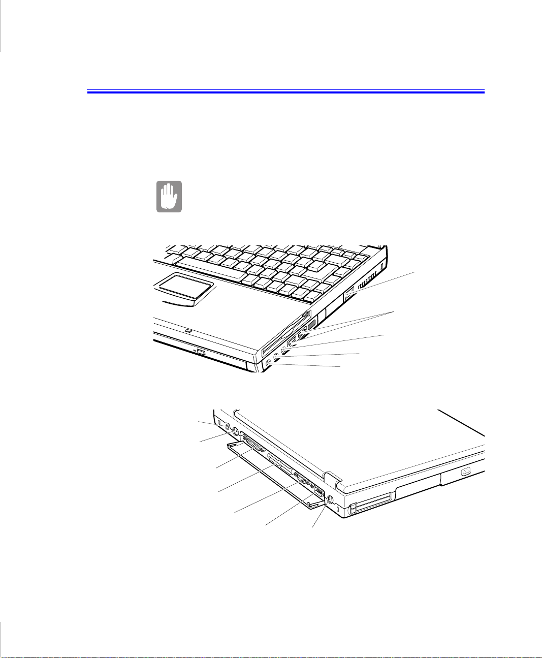
Connecting Peripheral Devices
The connectors on your computer ena ble you to attach peripheral device s to the
computer (Figure 12). The system in Figure 12 is based on 3-spindle type
computer, 2-spi ndle type computer has no internal floppy disk drive, but external
floppy connectors ins tead.
Turn off your computer before you connect a peripheral
device. Connecting a peripheral device with your comp uter
turned on may seriously damage the device or your
computer.
Headphone jack
Line-in jack
Modem
jack
USB ports
Mic-in jack
Power
connector
PS/2 mouse and
keyboa rd port
Parallel port
Docking connector
Video port
Serial port
TV-out port (S-VHS)
Figure 12. Peripheral Connectors
Connecting Peripheral Devices 21
Page 18
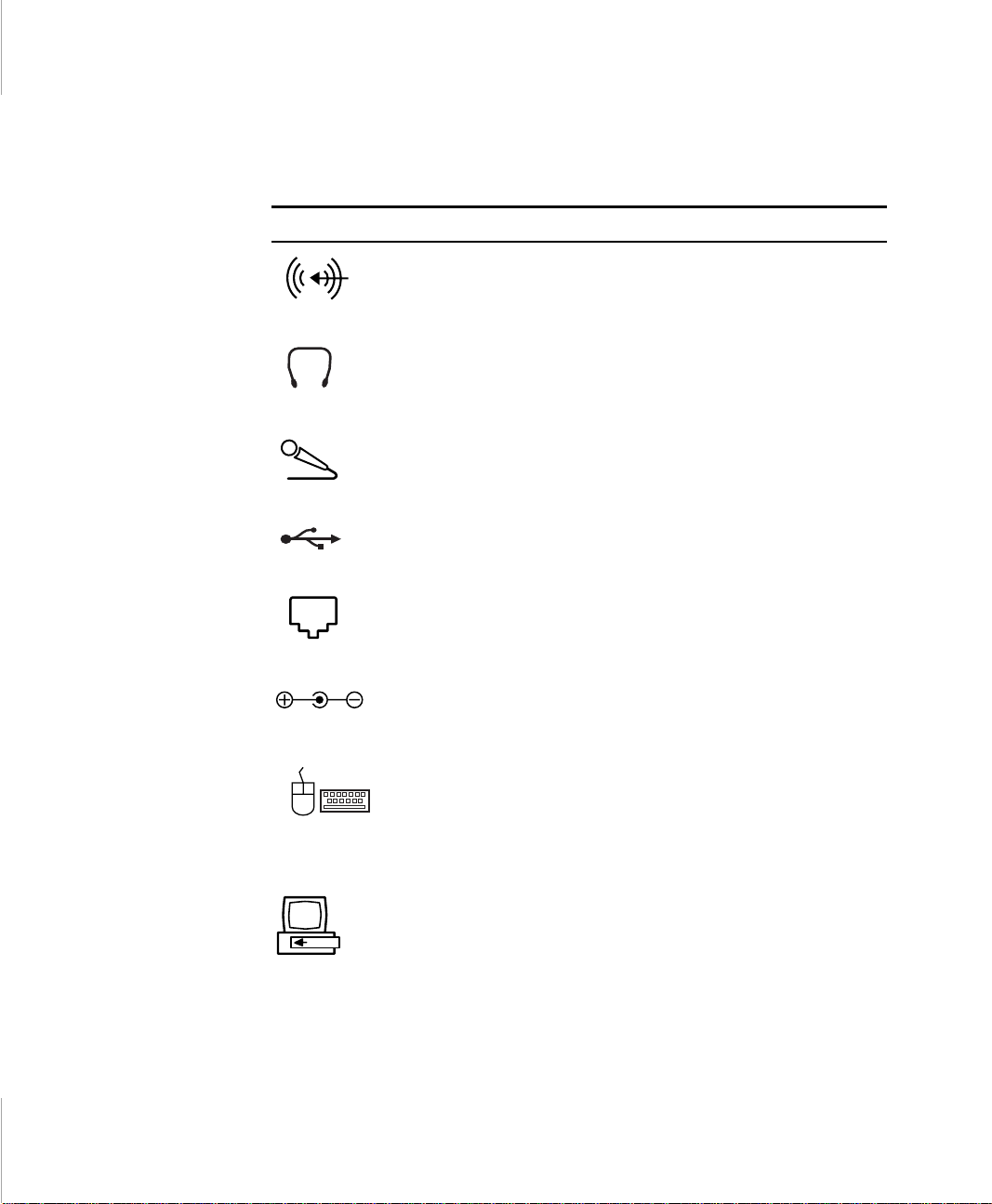
Table 4 shows the icons locat ed near e ach co nnecto r and t ells you the de vices that
you can attach to the connectors.
Table 4. Connecting Peripheral Devices
Icon Connector
Line-in jack:
Headphone jack :
jack. Speakers connected to this jack override the internal
speakers.
Microphone jack :
USB (universal serial bus) port:
USB input/out put devices include keyboards, pointing devices, and
monitors.
Modem jack:
Power cord connector:
and charge the battery.
PS/2 (Personal System/2) mouse and keyboard port:
PS/2-compatibl e mo use or external keyboard or keypad to this
port. Make sure your computer is turned off when you attach
peripherals to the por t.
You can use the computer’s touchpad and a PS/2 keyboard at the
same time.
Docking connector:
An input for external audi o.
Connect stereo headphones or speakers to this
Connect an external microphone to this jack.
Connect USB devices to this port.
Connect telephone line to connect to internet.
Plug in the power cord to run the computer
Connect a
Connect a docking option to this connector.
22 User’s Manual
Page 19
Using the Floppy Drive
Your computer com es wit h a 1. 44 MB, 3. 5-i nch, h igh-d ensity fl oppy dri ve, whi ch
can read, write to, and format the following disks :
• A high-density, 3. 5-inch disk, which stores 1.44 MB (megabytes) of data.
• A double-density, 3.5-inch disk, which stores 720 KB (kilobytes) of data.
The floppy drive in your notebook computer is smaller, but
more power-efficient, than a floppy drive in a desktop
computer. To get the best performance from your floppy drive
use hi gh-quality fl oppy dis ks.
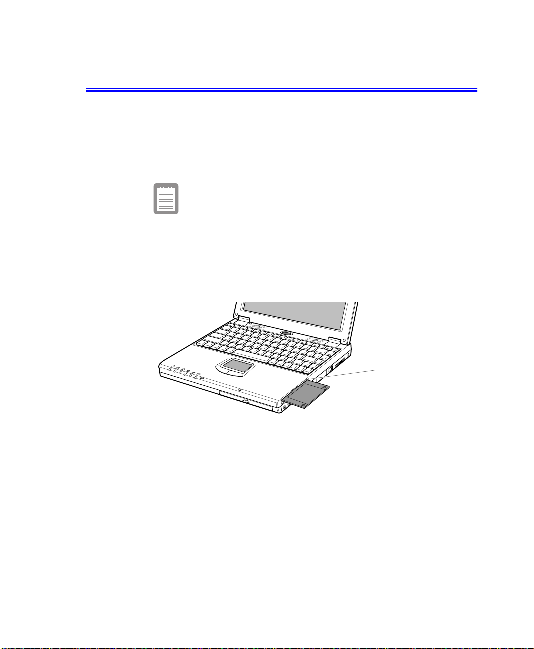
To use a floppy disk in 3-spindle type computer, insert it into the floppy drive
(Figure 13). Next figur e is b ased on 3-s pindl e type c omput er, see “Co nnecti ng the
Floppy Drive to the Floppy Conne ctor (2-spindl e type com puter only) ” on page 25
for using the 2-spindle type computer’s floppy drive.
24 User’s Manual
Floppy eject
button
Figure 13. Inserting a Floppy Disk (3-spindle type computer)
To remove a floppy disk, press the eject button on the floppy drive.
The floppy drive li ght on the c omputer is on when th e computer writes to or reads
from a floppy disk. Do not remove a disk when this light is on.
To protect the data on your floppy disks, follow these guidelines:
• Keep disks away from excess ive heat, direct sunlight, and liquids.
• Keep magnets and any de vice that contains a magne t (like the telephone)
away from your disks.
Page 20
Magnetic fields can destroy the information on a disk.
• Do not write di rectl y on a la bel on your di sk; i ns tead, wri te on a dis k labe l f irst
and attach the label to the disk.
• Make copies of all your important disks.
Connecting the Floppy Drive to the Floppy
Connector (2-spindle type computer only)
2-spindle type computer is shipped from the factory with both a floppy drive and
a CD-ROM drive includ ed.
Turn off your computer before you install or remove devices
from the drive bay or connect or disconnect the floppy cable
and drive.
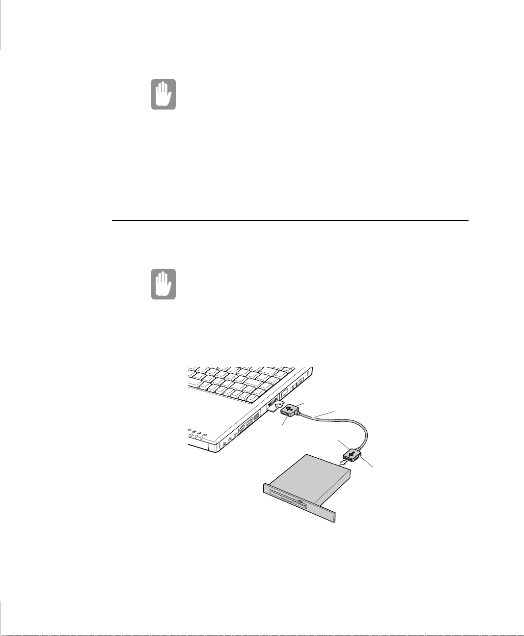
To use the floppy drive and the CD-ROM drive at the same time, install the CDROM drive in the drive bay. Then attach the floppy drive to the external floppy
connector. Att ac h one end of the floppy cabl e to the floppy drive and the other to
the external floppy port on the computer (Figure 14).
Tab
Tab
Floppy drive
Figure 14. Attaching the Floppy Drive to the Floppy Connector
Cable
Tab
Tab
Using the Floppy Dri ve 25
Page 21

The floppy cable must be inse rted as shown in Figure 14. To insert the cable
correctly, make sure that the connectors are fit to the cable connectors in proper
directio n.
If the cable does not fit easily, do not force it. Make sure you
have the correct end of the cable going to the computer and
to the floppy drive.
To remove the cable:
1. Pre ss in and hold the tabs on the side of each cable connector.
2. Pul l the cable connectors away from the floppy drive and the computer.
If you want to use floppy disk drive within the computer, then
insert the external floppy disk driver into the drive bay. See
”Using the Drive Bay” on page 30 for detail information.
26 User’s Manual
Page 22
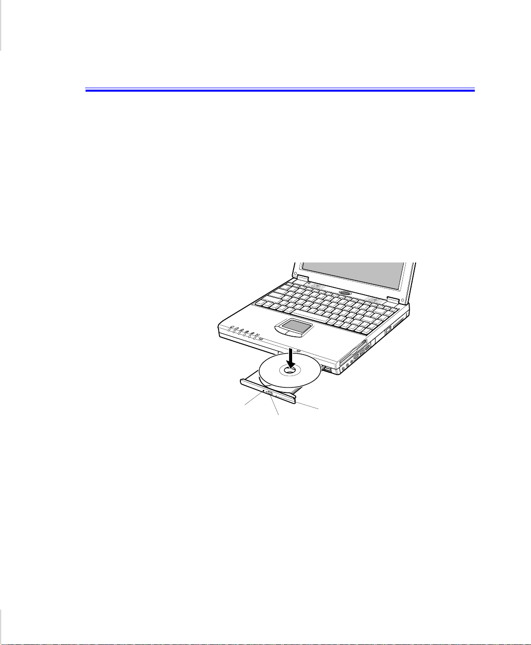
Using the CD-ROM Drive
Compact discs are designed so that you can easily insert one into the computer
when you need it, and then remove it:
1. Pre ss th e button on t he CD-ROM dri ve, a nd the t ray sli des out. (Do no t l ean on
the tray; it does not support much weight.)
2. I nsert a CD (c ompact disc ), label side up (or remove a di sc, if you have fi nished
using it).
3. Pus h the tray in gen tly to close the dri v e tray (Figure 15) .
A light o n the dr ive tray i s on whe n t he comput er is re ading fr om a CD. Do n ot
remove a disc when this light is on.
CD-ROM
Light
Button
Emergen cy ej ec t
button
Figure 15. Using the CD-ROM Drive
Install and start a CD-based progr am as you would run a pr ogram on a floppy disk.
See your operating system documentation for more information on running
programs.
The name of the CD-R OM d r ive is the lett er following the l etter assigned to your
last hard drive. For instance, if you have one hard drive with only one hard drive
partition, the hard drive is drive C and the CD-ROM drive is drive D.
Using the CD-ROM Drive 27
Page 23

If necessary, you can use the emergency eject button to open the CD-ROM drive.
To use the emergency eject button, turn the computer’s power off and insert a
small object, like an unbent papercl ip, into the hole to press the button.
Do not place reflective objects in the disc slot because of
possible hazardous laser emissions.
The laser beam used in this CD-ROM drive is harmful to the
eyes. Do not attempt to disassemble the CD-ROM drive. Refer
servicing to your authorized service center.
The on-board audio h ardware and sof tware of your com puter e nable t he comput er
to play audi o comp act di scs. If y ou wish to do s o, yo u c an att ach e xterna l spea kers
to the Headphone ja ck.
To play an audio compact disc:
1. Insert a compact disc into your CD-ROM drive:
a. Press the button on the CD-ROM drive, and its tray slid es out.
b. Insert a CD, label side up.
c. Push the tray in to clos e the drive tray. The CD Player button appears
on the ta sk bar.
The disc begins to play.
A light on the drive tray is on when the computer plays a CD. Do not remov e
a disc when this light is on.
28 User’s Manual
2. To adjust the sound, press the fol lowing key combinations:
• <Fn+F9> decreas es volume.
• <Fn+F10> incre as es volume.
To remove the CD:
1. Click the CD Player button on the Windows taskbar to open the CD Player
window (Figure 16).
Page 24
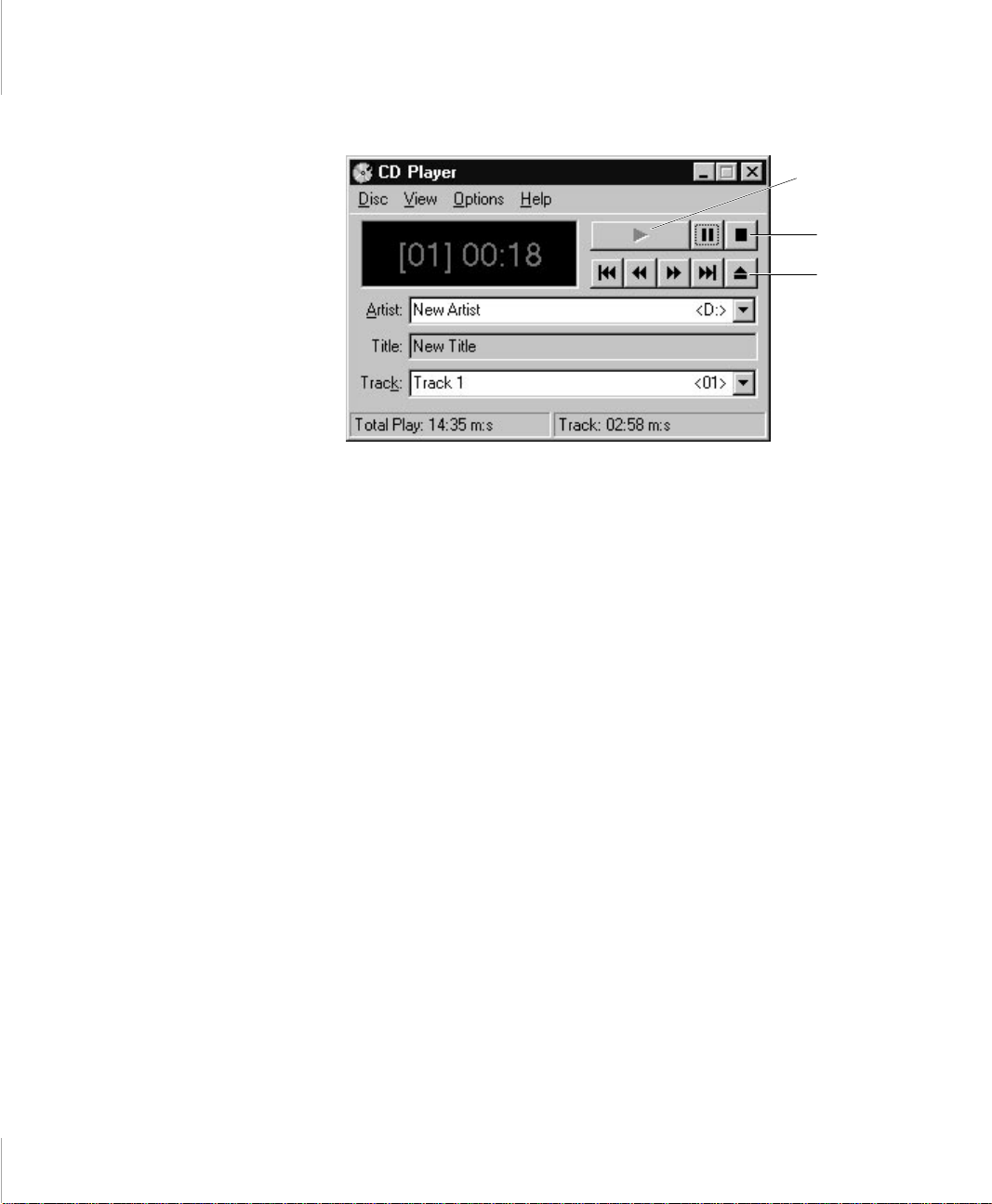
Play
Stop
Eject
Figure 16. CD Player Window
2. Click the Stop button in th e CD Player Window.
3. Click the Eject button on the CD Player window or press the button on your
CD-ROM drive. The drive tray opens and you can remove the disc fr om th e
CD-RO M dr i v e.
For more information on playing compact discs, see the Help menu in the CD
Player window.
Using the CD-ROM Drive 29
Page 25
Using the Drive Bay
Your computer includes the Drive bay, a peripheral bay that can hold one of the
following devices:
• Floppy disk drive: shipped with 2-spi ndle type computers.
• Optional secondary hard drive: availa ble as an option for your computer.
• DVD-ROM / Zip drive / LS-120: available as an option for your computer.
If your operating system is Windows 98, you can use the
SmartBay Utility to hot-swap the devices. If you do not use
Window 98, make sure that the computer’s power is off before
you remove or install any devices.
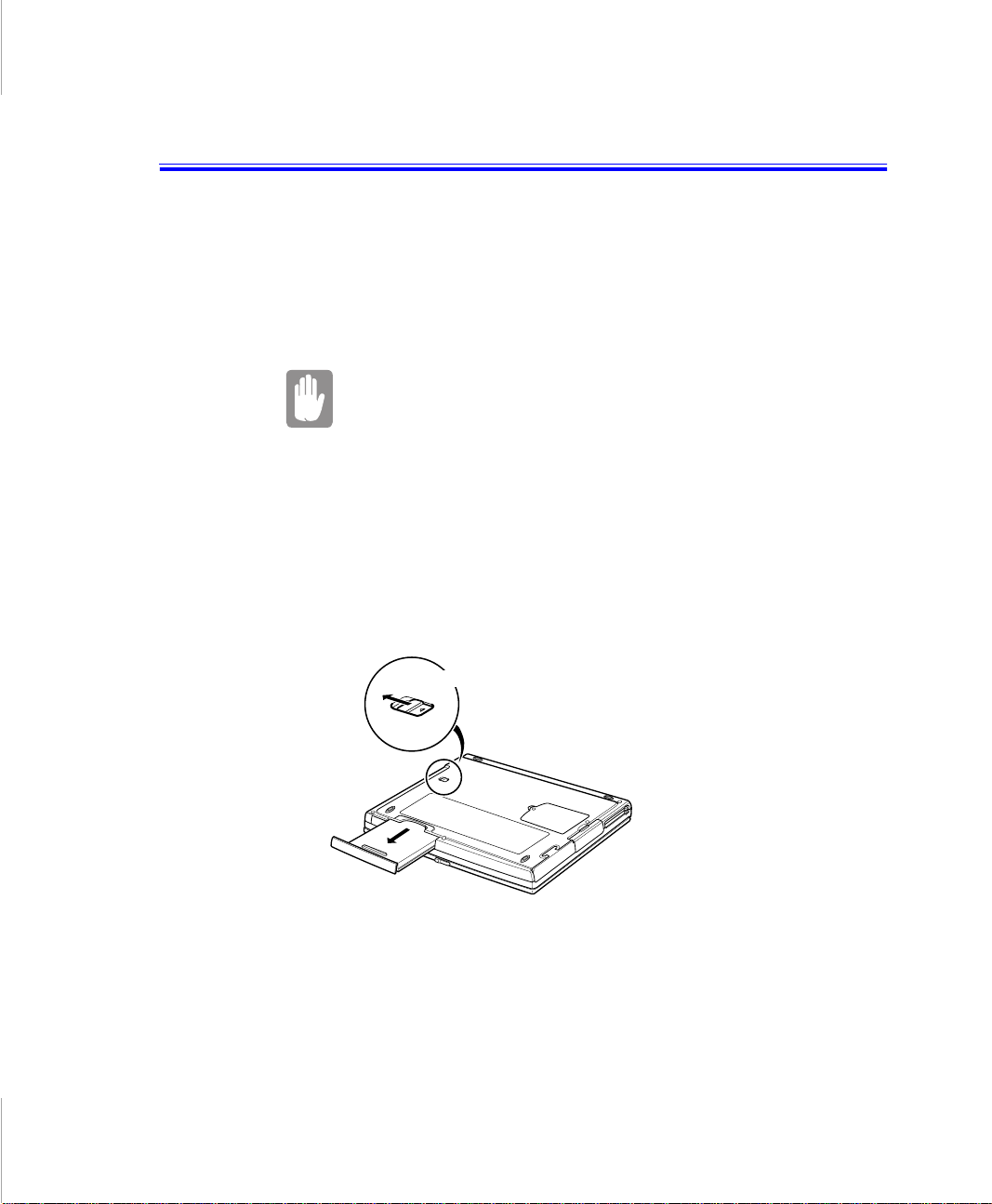
To remove a device from the drive bay:
1. Turn the computer’s power off.
2. Close the LCD panel, a nd turn t he com put er over s o tha t t he bott om of the uni t
faces up.
3. Pull up on the drive bay latch and pull the device from the bay.(Fi gure 17)
Drive bay latch
30 User’s Manual
Figure 17. Removing a Device from the drive bay
4. Remove the device out of the bay.
To install a devic e in the driv e b ay:
1. Turn the computer’s power off.
Page 26
2. Place the device into the bay.
3. Push the device in until it is flush with the chass is.
4. Push down on the drive bay latch unt il the latch snaps into place.
Your computer’s operating system automatically recognizes the device in the drive
bay and configures your computer accordingly.
To use the floppy drive and the CD-ROM drive at the same
time in 2-spindle type computer, install the CD-ROM drive in
the drive bay. Then attach the floppy drive to the external
floppy connector.
Using the SmartBay Utility
If your computer shipped with Windows 98, you can use the SmartBay utility to
hot-swap your devices.
To remove the device from the drive bay:
1. Double click SmartBay Hotswap Utility on the Windows .
To remove an device:
1. Open the SmartBay Hotswap Utility.
2. Select Remove Device and click Ok.
3. Click Yes on the confirmation screen
4. Remove the device by either disconnecting the cable from the computer or
from the device.
5. Click Ok.
To insert an device:
1. Open the SmartBay Hotswap Utility.
2. Select Insert Device and click Ok.
3. Connect the device to the comput er us ing the device cable. Make sure all
connectors are co rrectly attached .
4. Click Ok to allo w you r computer to detec t the device.
Using the Drive Bay 31
Page 27

If you have difficulty in getting an device detected, go through the Remove
procedure and then the Insert proc ed ure again.
32 User’s Manual
Page 28
Using the Hard Drive
Your computer includes a removable IDE (integrated drive electr onics) hard drive.
The IDE hard drive can store the data and progra ms your computer use s. The drive
plugs into a connector on the system board.
Although the storage c apacity of hard drives varie s according to model, any hard
drive holds much more than a floppy disk does. Also, the computer reads and
works with a hard drive more rapidly than with a floppy disk.
Once information is saved on a hard drive, it r emains there until it is overwritten.
Hard drive heads park automatically when you turn off your computer.
The hard drive that comes with your computer has already
been formatted. Do not format the hard drive. Doing so
destroys all data contained on the drive. If you need to format
a new drive, or want to erase all data on your existing hard
drive, refer to the manual for your operating system.
Removing the Hard Drive
To prevent loss of data and damage to the disk, do not
remove the hard drive while the computer’s power is on and
do not drop or jar t he hard drive.
To remove the hard drive from the computer:
1. If you are installing a new hard drive, backup the application and dat a files on
the old hard drive before removing it from the computer.
In Windows 9 8, you c an use t he Micros oft Crea te Sys tem Dis ks Ut ility t o b ack
up application files and the Microsoft Backup Utilit y to back up data files.
In Windows NT, yo u can use the Windows NT Bac kup Utility to backup data
files. T he Backup Utility requires a tape drive. You can a ls o back up files to a
network.
2. Turn the computer’s power off.
Using the Hard Drive 33
Page 29
3. Close the LCD panel, a nd turn t he com put er over s o tha t t he bott om of the uni t
faces up.
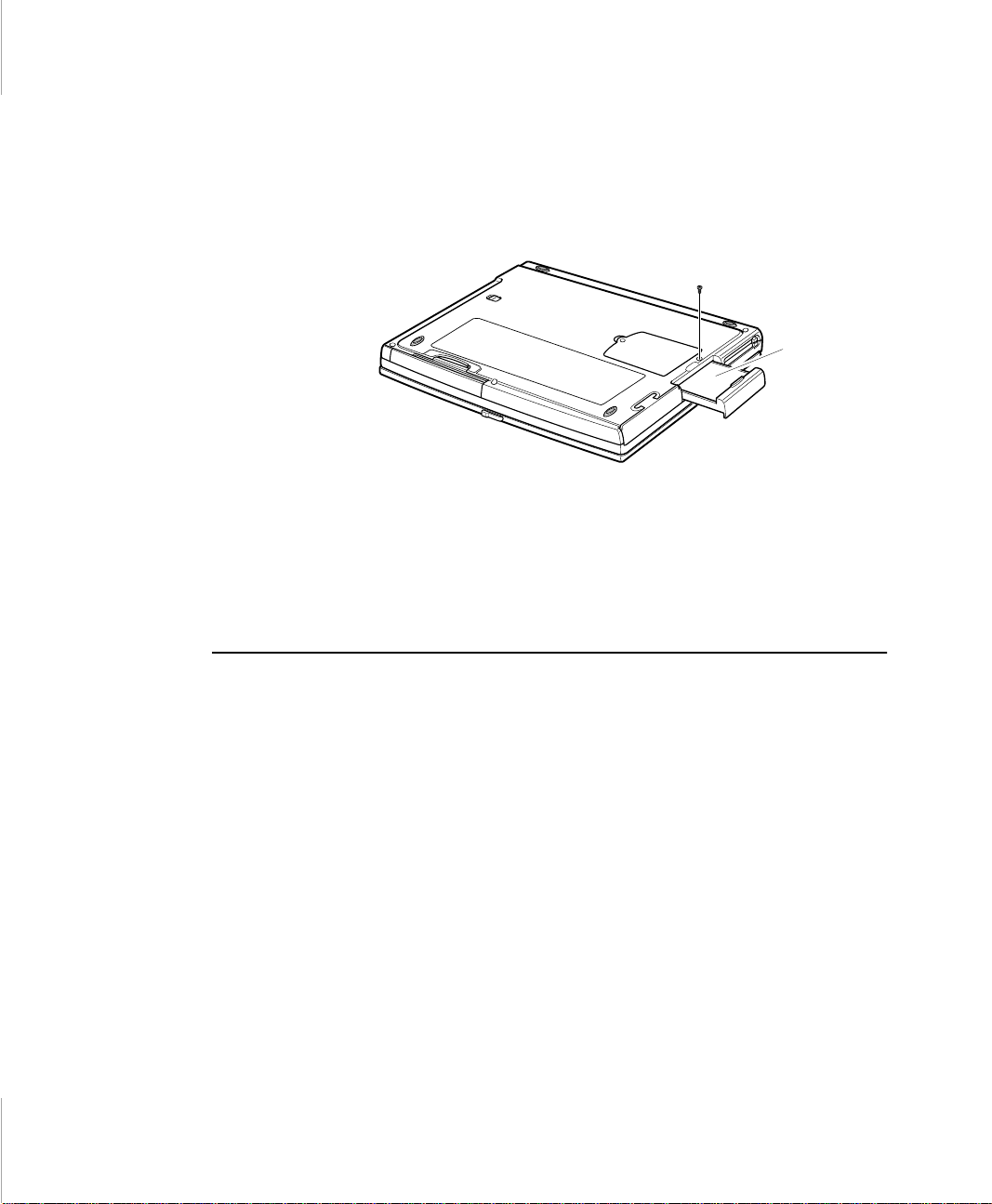
4. Remove the screw that holds the hard drive in place (Figure 18).
Figure 18. Removing the Hard Drive
5. Pull the hard drive out of the computer.
Installing a Hard Drive
Bottom of
computer
Hard-drive
34 User’s Manual
To install a hard dr iv e:
1. Remove the old hard drive from the computer as described in the previous
section.
2. Slide the new drive into the hard drive compartment. Make sure the drive is
pushed back as far as it will go.
3. Install the scr ew that holds the hard dr ive in place.
4. If you intend to use save to disk mode, see “Creat in g a Save to Disk Partit ion”
on pag e 61 .
5. Format your drive and reinstall your files.
Page 30

Using the Battery
Your computer uses a rechargeable Lithium-ion (Li-ion) battery pack for powe r
when th e po w er co r d is no t at ta ch ed to an elec tr i ca l ou t le t.
Charging the Battery
Your computer’s batt ery s tarts charging automatically when you connect the
power cord to the computer and to an e lectrical o u tlet. If t he computer is off, the
battery charges faster than if the computer’s power is on.
Approximate charging times for Li-Ion battery are
• 3 hours with the computer off.
• 5 hours with the computer on.
While the bat ter y is c harging norm ally, the ba tt ery cha rge light on th e co mputer is
amber (See ”Syst em St atus Lights” on page 19 for the location of the battery
charge light). When the battery is fully charged, the light changes to green.
When you use a new battery pack for the first time or use a battery after a long
period of stora ge, t he i nitia l ba ttery lif e is s hor ter tha n nor mal. Normal batte ry li fe
resumes after a few discharge-recharge cycles.
Follow these rule s for charging your battery:
• A battery normally discharges power when not used for long periods of time.
Be sure to recharge the battery every two months when it is not in use.
• Make it a practice to discharge your battery fully before recharging the
battery. T his can help extend the life of the battery.
• Do not attempt to charge the battery in temperatures of under
o
over 95
F (35oC
All batteries eventually wear out and lose the ability to hold a
charge. You may need to replace your battery pack after a
year of average usage.
.)
41o F (5o C) or
Using t h e Bat t er y 35
Page 31

Safely Using the Battery
Follow these guidelines to safely use the battery:
• Turn off your computer and unplug it if you accidentally:
– Expose the equipment to liquid.
– Drop, jar, or damage the computer.
• Use only approved battery chargers.
• Do not disassemble the battery, heat it above 212° F (100° C), or burn it. The
battery used in this computer may cause a fire or chemical burn if mistreated.
• Your computer's rechargeable battery may be considered hazardous waste. If
you replace your battery with a new one:
– Keep the old battery out of the reach of children.
– Dispose of the old batte ry promptly.
– Make sure that you follow all local requirements when you dispose of
the old battery.
Removing the Battery
To remove the battery from the computer:
36 User’s Manual
1. Turn the computer’s power off.
2. Close the LCD panel, a nd turn t he com put er over s o tha t t he bott om of the uni t
faces up.
3. Slide the battery compartment cover straight up and off th e computer (Figure
19).
Page 32
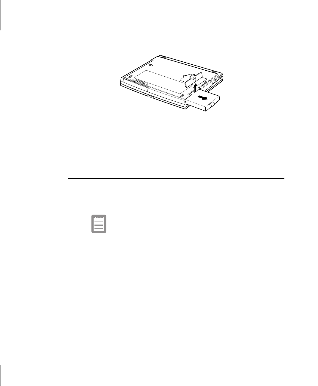
Figure 19. Removing the Battery Pack
4. Grasp the tab on the battery and pull the battery out of the compartment.
See ”Installing the Battery” for information on installing the battery.
Monitoring the Battery Charge
Battery life is affected by factors such as the power-m anagement s ettings in
System Setup, th e applications you use , and the brightness settings of the LCD.
Under normal usage, the battery charge lasts approximately 3 hours.
Battery life estimates are subject to variation. The actual life
of your battery may be less than the estimates given in the
manual.
You can monitor th e charge of the bat tery pack i nsta ll ed in you r comp uter t hrou gh
the battery gauge.
Using the Battery Gauge
Press <Fn+F6> to displ ay the battery gauge on the LCD
(Figure 20). You can display the battery gauge while you are in any program.
Using t h e Bat t er y 37
Page 33
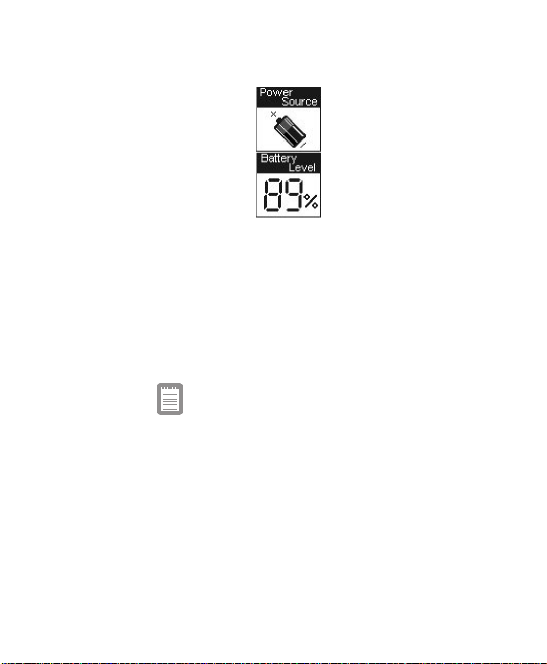
Figure 20. Battery Gauge
The gauge has two sections:
• The top sectio n of the gauge shows an icon of a battery to indicate that the
computer is powe red by the batt ery or an icon of a powe r cor d plug t o indica te
that the computer is powered by the internal AC adapter.
• The bottom secti on of t he gauge sho ws you the app roxi mate amount of batte ry
charge remaini ng. This section of the gauge is onl y displayed if the computer
is being powered by the battery.
While the battery gauge is displayed , all keys except <Esc> are disabled. The
battery gauge clos es in a fe w seconds, or you can press <Esc> to clos e it.
Because of the characteristics of battery cells, the battery
gauge may be inaccurate for 10 minutes after you charge the
battery. Wait until the computer has been operating from the
battery for 10 minutes before you check the battery gauge.
38 User’s Manual
Page 34

Battery Warnings
Your computer gives you th e following low-battery warn ings (Table 5).
Table 5. Battery Warnings
Warnings Condition Action to Ta ke
The computer beeps 5
times (low-pitched
beeps). In Windows 98,
a battery-low warning
appears on screen.
The computer beeps 5
times (high-pitched
beeps), wit h a shor t time
between beeps. After a
short ti me , the computer
automatically goes into
rest mode.
Battery low: The battery
charge is about 10
percent. Appr oximately
5–10 minutes of bat tery
charge is left.
Battery very low: The
battery charge is about 3
percent.
Save your work. Use the
power cord to power the
computer or turn off the
computer and ins tall a f ully
charged battery.
Use the power cord to
power the computer and
charge the battery.
Above features are valid with only APM OS except Windows 98. In case of any
ACPI OS and Windows 98 whic h i s runni ng on APM int erfac e, you can a dju st th e
battery alarm featur es by us ing OS spec ific powe r management progra m (Control
Panel > Power management in Windows 95). But, in APM Windows 98, unlike
ACPI OS, you should select the Rest mode of low battery situation (Power On
Suspend/Save-to-Disk) only in BIOS setup.
If you cannot run your computer from the battery and the battery will not charge
when you attach the power cord, the problem may be that
• The battery temperature is over 41° F (5° C) or below 95° F (35° C). If you
think the battery temperatu r e is too hot or too cold, turn off the com puter,
remove the battery, and let the bat tery reach room temperat ure. Then try
charging the battery again.
• The battery is de fective. Replace the battery with a new battery.
Using t h e Bat t er y 39
Page 35
Using System Setup
The System Setup progr am enabl es you to confi gure your computer ha rdware and
set security and power-savings options. The settings you choose are stored in
battery-mainta ined CMOS (compl ementary metal-oxi de semicondu cto r) memory
that saves the information even when the compute r’s power is turned off. When
your computer is turned back on, it is configured with the values found in this
memory.
Run System Setup if you get a message prompting you to run the progra m. You
may also want to run System Setup, particularly th e firs t time you use your
computer, to set t he t ime and da te, u se sec urity or po wer-man agement f ea tures, or
alter the settings of other features.
Your computer’s version of System Setup may not include all
the fields listed here or may include additional fields. Field
names and order of appearance can vary accor ding to the
version of the BIOS (basic input/output system) on your
computer.
You can use the configuration listing at the back of this manual to record
information specific to your computer. (see “Recording the Computer Hardware
Configurati on” .) Fill it out as y ou complete your System Set up configuration . This
list helps you desc ribe your co mpute r if you must cont act you r auth orized reselle r
for service or product information.
Starting System Setup
To start System Setup, turn on your computer and then press <F2> when
prompted. The System Setup screen appears.
The top of the System Setup screen has a menu bar with the se lections listed in
Table 6.
Table 6. System Setup Menus
Menu Function
Main Changes the basic system configuration.
40 User’s Manual
Page 36

Advanced Configures advanced features on your
computer.
Security Enables security features, incl uding
passwords and backup and virus-check
reminders.
Power Configures power-management feat ures.
Boot Specifies the order of boot devices and
configures boot features.
Exit Specifies how t o exit System Setup.
To open a menu, use the left or righ t arr ow keys to sel ect the menu name and the n
press <Enter>.
Table 7 lists the keys you ca n us e to navigate through Syst em Setup.
Table 7. System Setup Navigation Keys
Navigation
Key
<F1> <Alt+H> Displays the Genera l Help window.
<Esc> Exits the current menu.
<Left Arrow>
and <Right
Arrow> keys
<Up A rro w >
and <Down
Arrow> keys
<Tab> Moves the cursor forward through the cell s for a
<Tab+Shift> Moves the c ursor backward through the cells for
<Home> <PgUp> Moves the cursor to the field at the t op of th e
<End> <PgDn> Moves the cursor to the fie ld at the bottom of the
Alternate
Key
Keypad
arrow keys
Keypad
arrow keys
Function
Select a different menu.
Move the cursor up and down between fields.
highlighted fi eld. If t he fie ld has o nly one cel l, th e
<Tab> key moves the cursor down to the next
field.
a highlighted field. If the field has only one cell,
the <Tab+Shift> key combination moves the
cursor up to the previous field.
window.
window.
Using System Setup 41
Page 37

<F5> <-> Scrolls backwards through the options for the
highlighted field.
<F6> <+> or
<Space>
<F9> Sets the parameters for the current menu to
<F10> Sets the par am eters for the current menu to
<Enter> Executes commands or opens a submenu.
Scrolls forward through the options for the
highlighted field.
their default val ues.
their previo us values.
A pointer symbol appearing to the left of a field indicates that you can open a
submenu from this field. A submenu contains additional options for a field. To
open a submenu, hig hli ght t he fie ld and pr ess <Enter > . Use the s ame keys to ent er
values and move from field to field within submenus as you use wit hin menus.
When you highlight a field , informati on about the fie ld appears on the right side of
the screen. System Setup also provides a General Help screen that ca n be ope ned
from any menu by pressing <F1> or <Alt+H>. The General Help screen lists the
navigation keys with their corresponding alternates and functions.
When a scroll bar appears to the right of a help window, more information is
available than c an be displayed in th e window. Use the <PgUp > and <PgDn> keys
or the <Up Arrow> and <Down Arrow> keys to scroll through the entire help
document. Press <Ho me> to display the first page , or press <End> to go to the last
page. To exit the help window, press <Enter> or <Esc>.
Main Menu
42 User’s Manual
If your compu ter will not bo ot after you have changed settin gs in Sys tem Setup and
exited the progra m, reboot and press <F2> to reenter System Setup. Once in
System Setup, you can try to change the values that ca used your computer boot to
fail. If the problem persi sts, press <F9> to load the default values.
When you open System Setup, the Main menu a ppears . You can make changes to
your computer’s b asic system configura tion from this menu. The fields displayed
in this menu are described below.
System Time: Sets your compute r t o t he ti me t hat y ou spe cif y, us uall y t he cu rrent
time. Enter the hour, minute, and second in the format hh:mm:ss. Use a 24-hour
Page 38

clock. Use the tab key to move betwee n the hour, minute, and second cells. Use
the hyphen key <-> or <Space> bar to decrease or increase the number s.
System Date: Sets your computer to the date that you specify, usually t he current
date. Enter the month, day, and year in the format mm: dd:yyyy. Use the tab ke y to
move between t he mon th, da y, an d year ce lls. Us e th e h yphen ke y <-> or <Space >
bar to decrease or increa se the numbers. This f ield supports year da tes of 2000 and
beyond.
Diskette A: Specifies a drive type for floppy drive A. 1.44 MB, 3 1/2 ”(default)
floppy disk can be used.
Primary Master and Secondary Master: Your computer can support two IDE
drives. The Main menu contains two IDE adapter fields to configu r e these drives.
Prima ry Master defines the hard drive installed in the computer. Secondary
Master defines the CD-ROM drive.
To configure a replacement or upgrade hard drive, move the cursor to select the
Prima ry Ma st er fie ld in the System S etup Mai n menu, and then press the < Ente r>
key. The submenu appears .
Normally, you can use the Auto option of the Type fiel d in the submenu to
automatically set the values for th e other fields in the submenu. Manually set the
other fields in this submenu only if the drive you have installed in your computer
is not recognized by Sys tem Setup.
After you make your selecti ons from this submenu, press the <Esc> key to exit
back to the Mai n menu.
Set the Auto option of the Type field in the Secondary Master submenu, if you
want CD-ROM boot.
Before attempting to configure a hard drive, make sure you
have the configuration information supplied by the
manufacturer of the hard drive. Incorrect drive settings can
cause your computer to malfunction.
Primary and Secondary Master field calls up a subm enu. The following fields are
found in the submenu:
Type: Configures the hard drive type. Normally, select Auto at this field to
have your computer attempt to automatically detect the drive type and set the
value s for th e remaini ng fields in th is subme n u
Using System Setup 43
Page 39

You can also enter the driv e type number (1-39) for your drive or select CDROM. All rema ining fields in this submenu are then filled with the co r r ect
values for the dis k type. If you do not have the documentat ion that came with
your upgrade hard drive, try to use the Auto option as describe d above.
To configure a dri ve that is not one of the 39 standard drive types, specify
User. Manually enter the number of cylinders, heads, sectors per track, and
write precompensation for your drive. Refer to your dri ve’s user
documentation or look on the drive to obtain this information.
If no drive is installed or if you are removing a drive and not replacing it,
select None.
Cylinders: Configures the number of cylinders for the hard drive. Refer to
your drive’s user documentation or look on the dri ve to obtain this
informatio n. Before you can make chan ges to this fi eld, t he Type field must be
set to User.
Heads: Configures the number of read/writ e heads for th e hard drive . Refer to
your drive’s user documentation or look on the dri ve to determine the correct
value to enter f or this field. Before you can make chan ges to this field, the
Type field must be set to User.
Sectors: Configures the numb er of s ec tors per track for the hard drive. Refer
to your drive’s user documentation or look on the drive to determine the
correct value to enter for this field. Before you can make changes to this field,
the Type field must be set to User.
Maximum Capacity: Shows the maximum capa city of the drive. This field is
for reference only.
Multi-Sector Transfers: Sets the number of sectors per block to the highest
number supp orted by the driv e. Conf igura tion op tio ns are Disabl ed, 2 S ectors ,
4 Sectors, 8 Sectors, and 16 Sectors.
LBA Mode Control: Enables or disables 28-bit addressing of the hard drive,
without regard for cylinders, heads, an d sectors. Note tha t enabling this fi eld
may decre a s e th e access speed o f th e har d dri v e.
32 Bit I/O: Enables or d isables 32 -Bit I/ O (inp ut/outp ut). When En abled , your
hard drive can work with app li catio ns with 32-bi t input a nd outp ut. If the field
is Disabled (default), your computer works with 16-bit input and output and
has lower performance.
Transfer Mode: Selects the method for transferring data between the hard
drive and system memory. Refer to your drive’s user doc umentation to
specify the correct option for this field. Opti ons are Standard , Fa st PIO 1,
Fast PIO 2, Fast PIO 3, and Fast PIO 4.
44 User’s Manual
Page 40

Smart Monitoring: Defult setting is Enabl ed. Showes that Smart Monitor ing
function is used. Th is field is for reference only.
Ultra DMA Mode: Enables the hard drive to use ultra DMA (direct memory
access) transfer mode to transfer data between the drive and system memory.
Options are Mode 0, Mode 1, Mode 2, and Disabl ed.
Memory Ca che: Enables or disables the exter nal cach e memory . Cache memory
improves system perf ormance by keeping freque ntly used compute r instructions in
memory with a faster a cce ss time than DR AM (dyn amic ra ndom a ccess memory).
Normally, do not disa ble the cache memory unless a program’s documentation
specifies that the computer cache memory must be disabled.
System Memory: Displays the amoun t of conv entiona l me mory detec ted by your
computer during startup. This field is for reference only.
Extended Memory: Displays the amount of ext ended memory detected by your
computer during startup. This field is for reference only.
Advanced Menu
Selecting Advanced from the menu bar displays the Advanced menu.
Installed O/S: Select the operating system installed on your syste m which you
will use most commonly. An incorrect sett ing can cause the unexpected system
behavior.
PS/2 Mouse Configuration: Disabled prevents both the touchpad and external
PS/2 port from functioning. Single mouse enables the external PS/2 p o r t o r th e
touchpad, and external PS/2 port has proirity. Dual Mouse allows the use of both
the touchpad and PS/2 port.
Screen Expansion: Enables or disables the Scr een Expansion mode. If you set th is
field to Ena bled, syste m dis play s the VGA mode (DOS mode or 640x480 Gra phi c
mode) to expansion mode.
TV Standard: Select TV standard such as NTSC(default ), PAL, and SCART- PAL.
Display Control: Enables or disables the display using the LCD or external
monitor. Or both(defaul t) synchronizely.
I/O Device Configuration: Opens the I/O Device Configuration submenu if you
press <Enter> whe n this field is highlighted. If you attempt to s et two ports to the
same settings, the fields will be marked with asterisks.
Using System Setup 45
Page 41

The submenu contains these fields:
Serial port: Configures serial port. The options for this field are Enabled
(default), and Disabled. If you set this field to Enabl ed, you can set the Ba se I/
O Address field to 3F8 IRQ4 (default), 2F8 IRQ3, 3E8 IRQ4, or 2E8 IRQ3.
When the field is set to Enabled, the computer’s operating system uses the
default configuration or the configuration you choose. If you select Disabled,
you free up an IRQ for use by another device .
Infrared port: Configures the infrared port. The opti ons for this field are
Enabled, and Disabled (default). If you set this field to Enabled, you can set
the Base I/O Addr ess field and the Mode field and the Mode field. Settings for
the Base I/O Address are 3F8 IRQ4, 2F8 IRQ3 (default), 3E8 IRQ4, or 2E8
IRQ3. Mode FIR (fast infrared) enables you to set the DMA channel to 3 or 1.
When the Infrared port field is set to Enabled, t h e computer’s operating
system uses the de fault configuration or the configuration you choose. If you
select Disabled, you free up an IRQ for use by another device.
Parallel po rt : Configures the parallel port. The options for this field are
Enabled (default), and Disabled. If you set this fi eld to Enabled, you can set
the Mode field and the Base I/O Address field. Settings for the Base I/O
Address ar e 378 IRQ7(default), 378 IRQ5, 278 IRQ7, 278 IRO5, 3RC IRQ7,
and 3RC IRQ5. Settings for the Mode are Out put only, Bi-directional, EPP
(enhanced paral lel port), and ECP (extended capabi lities port). S electing the
ECP setting enables you to set the DMA Channel to 1, 2, or 3.
When the Paralle l port field is set to Enabled, the computer ’ s op e r at in g
system uses the de fault configuration or the configuration you choose. If you
select Disabled, you free up an IRQ for use by another device.
Floppy disk controller: Configures the floppy disk controller. The options
for this field are Enabled (default), and Disabled. When the Floppy disk
controller field is se t to Enabled, the compu t er ’ s op e r ating sys te m use s th e
default configuration for the controller.
46 User’s Manual
Local Bus IDE adapt er: Enables the integrated IDE local bus adapters. Options
are Enabled (default) and Disabled.
Large Disk Access Mode: Enables your computer’s opera ting system to work
with drives large r than 540 MB. Choose DOS (default) for Microsoft operating
systems. Choose Other for any other operating systems.
Page 42

Security Menu
Selecting Security from the menu bar displays the Security m enu. Your computer’s
advanced security sys tem allows you to set two different passwords to prevent
unauthorized access to system resources, data, and System Setup. From the
Security menu, you can enab le a boot password, disk acces s, a sy st em backup
reminder, and a virus check reminder.
Security fields marked with an asterisk can only be changed if you start System
Setup with a system supervisor password or if no passwords are in effect. You
cannot access these fields with a user password.
Set User Password: Enables you to set a user pas sword to control access to the
system at boot. See ” C reati ng a Pas sword” on page 53 for instr uctions on s ettin g a
password.The user pass word allows restri cted access to t he System Setup Security
menu; the user has access only to changing his own password and to enabling or
disabling Password on boot. A supervisor pass w ord m ust be set before a user
password can be set
Set Supervisor Password:* Enables you to set the supe rvisor pass word to control
access to the System Set up utility. See ”Creating a Password” on page 53 for
instruction s on setting a password.
Password on boot: Determines whether the comput er prom pts for a password
when starting up. The options are Enabled and Disabled. A supervisor password
must be set before you can enable this option.
Fixed disk boot sector:* Enables you to write-pr otect the hard drive boot sector
to protect ag ainst virus es and alte rations. Onl y a user wit h the supervi sor password
can access this fi eld. The options for this field are Normal (default) and Write
Protect.
Diskette access:.* Enables you to restrict the use of floppy drives. When set to
Supervisor (default), the use of floppy drives is restricted to a user with the
supervisor password . A supervisor password must be enabled before the
Supervisor option can take effect. Whe n se t to User, users with either type of
password have access to floppy drives. If the field is set to Supervisor and a user
password is enabled, the user must e nter the supervi so r pas s w ord in order to boot
from the floppy drive.
Virus check reminder:* Enables the computer to prompt you to scan the
computer for viruses. The prompt appears each time you start your computer or
reboot until you respond with Y (yes). The options for this field are:
Using System Setup 47
Page 43

• Daily: Every day when you star t your computer for the first time, the prompt
appears.
• Weekly: When you start your co mp u t er fo r th e fi rs t tim e each week (a fte r
Sunday), the prom pt appears.
• Monthly: When you start your c omp uter for the first time each month, the
prompt appea r s.
• Disabled: The prompt never appears. This is the default setting.
For a Daily, Weekly, or Monthly prompt to be accurate, System Date in the Main
menu must be set to the current date.
System backup reminder:* Enables the computer to prompt you to backu p your
files. The prompt appears each time you start your computer or reboot until you
respond with Y (yes). The options for this field are
• Daily: Every day when you start your computer for the first time, the prompt
appears.
• Weekly: When you start your co mp u t er fo r th e fi rs t tim e each week (a fte r
Sunday), the prom pt appears.
• Monthly: When you start your c omp uter for the first time each month, the
system backup prompt appears.
• Disabled: The prompt never appears. This is the default setting.
For a Daily, Weekly, or Monthly prompt to be accurate, System Date in the Main
menu must be set to the current date.
Power Menu
48 User’s Manual
The Power menu of System Setup allo ws you to enable a nd adjus t your compute r’s
sophisticat ed power-savi ng feature s. Enabli ng these fea tures exte nds the life of th e
battery.
If your computer shipped with Windows 98 installed, the
Power Management works as the settings in Power
Managem e nt option of Contr ol Panel. But if your co m pu t er
boots with DOS or Windows 95, Windows NT 4.0, the Power
Management works as the settings in System Setu p.
Page 44

Power Savings Mode: Enables an d disables Maximum Perfor mance mode. The
options are Maximum Performance, Maximum Power Saving(default),
Customized and Disabled. If you set thi s fi eld to Maximum Performance, the
microprocessor and hard drive run at full speed, unless affected by other powersavings settings. If you set this field to Maximum Power Saving, the
microprocessor and the hard drive run at slow speed, unless there is user input or
device activi ty. Choose Custo miz ed t o al te r th ese s ett ings and Disabl ed to turn off
the Power management function.
Idle Mode: Turns on or off the idle mode power savings. On slows down the CPU
during brief period when the system is not busy.
Standby Timeout: Sets the period of com puter i nacti vit y (no user i nput or de vic e
activity) tha t mu st pas s before your computer automat ically goes into standby
mode. In standby mode some devices are turned off (including the LCD screen)
and the microprocesso r slows down. You can disabl e this option by sele cting Off,
or you can specify a Standby Timeout delay time of from 1 to 16 minutes. The
default is 1 Minute.
Rest Time out: Sets the pe riod of comput er inacti vity from st andby that must pass
before your computer aut oma tically goes into rest m ode. When the rest timeout
expired, your computer goes to the rest mode according to Rest Mode.
Rest Mode: Specifies the type of rest mode your computer enters:
• Power On Suspend: Saves power by turning off the micropro cessor a nd DMA
clocks, vide o, and all c ontroll abl e perip hera l devi ces. Some powe r is stil l us ed
when your system is in this mode.
• Save T o Di s k (default): Provides the greatest power-saving capabilities by
essentia lly turning off your computer. In the save to disk mode, all system
logic (except for your c omp uter wakeup circuitry and battery charger) is
turned off. Duri ng sa ve to di sk mode, the DRAM a nd video memory ar e saved
to the hard drive and are restored when your compute r resum es from rest.
When the computer enters save to disk mode, it will not resume normal
operat io n at a s p ec if i ed ti m e n o matter how th e Resume On Time field is set.
Hard Disk Timeout: Sets the amount of time the hard disk needs to be inactive
before it is turned off.
Resume On Modem Ring: Enables the computer to resume operation from rest
mode in the event of mode m communicatio n. The computer will resume only if the
Rest Mode fi eld is se t t o Power On Suspend, not Save To Di sk. The defa ult sett ing
is Off. Windows 98 do not use this item.
Using System Setup 49
Page 45

Resume On Time: Ena bles the c omputer to resum e ope ration from rest mode at a
scheduled time. The computer will resume only if th e Rest Mode field is set to
Power On Suspend, not Save To Disk. If you set this field to On, you must set the
Resume Time field as well. The defaul t sett ing is Off. Windows 98 do not use this
item.
Resume Ti me: Specifies the time for your co mputer to automatical ly resume from
rest mode. Enter two-digit numbers to indicate the hour, minutes, and seconds in
the format hh:mm:ss. Use a 24-hour clock. Use the tab key to move between the
hour, minute, and sec ond cell s. Use t he hyphen key <-> o r <Space> ba r to dec rease
or increase the numbers.
You must set this option if you enable Resume On Time.
Thermal Con t ro l: Enables the computer to be slowed down when the CPU is
overheated (defau lt a nd recomm anded). When yo u need s pecia l working, you c an
select disabled . I n this case, the CPU te mpe r ature is not monitored.
Boot Menu
The Boot menu enable s you to select a boot device and set boot options.
QuietBoot Mode: Enables ot Diables the display of the diagnostic screen during
boot. If you select Enabled(default) , the diagnos tic screen is dis abled.
QuickBoot Mode: Allows the system to skip certain tests w hile boo ting for
decreasing the boot time.
50 User’s Manual
Flopp y check: Enables a c heck of the floppy drive during the tests performed by
the computer at startu p. When this field is ena bled, a c omplete POST is perfor med
at startup. The options are Enabled and Disabled(default).
Bootable CD check: Enabl es a che ck of the CD-ROM drive during the tests
performed by the computer at startup. When this field is enabled, a complete POST
is performed at startup. The options are Enabled and Disabled(default).
Summary screen: Displa y s the system configuration when the comput er starts.
The options are E nabled and Disabled(default).
Wake On Lan: Control magic packet. If a dock device included LAN controller
is docked, the wake on Lan capabilities are available. This menu can be shown o n
docking.
Page 46

Boot Device Priority: Enables you to select the order in which the computer
attempts to boot from different devices. The f ield has three options : Diskette Drive,
Hard Drive, and ATAPI CD-ROM Drive.
To choose a device as the first, second, or third boot device:
1. Press <Enter > at the Boot Device Priority field
2. Highlight the option with the <Up Arrow> or <Down Arrow> key .
3. Press the <Space> bar until the option moves up or down in the list of opt ions
and the number 1, 2, or 3 appears beside the option.
4. Press <Esc> to return to the Boot menu.
The defaul t setting is 1.Diskette Drive , 2. Hard Drive, and 3. ATAPI CD-ROM
Drive.
Exit Menu
If you want to start the system by bootable CD, put the ATAPI
CD-ROM Drive at first of the Boot Device Priority and set the
Auto option of the Type field in the IDE Adapter 1 Submenu at
Main page.
Select Exit from the menu bar to display the Exit menu.
Pressing <Esc> does not exit this menu. You must select one
of the option s fr om t hi s me nu or a menu bar item to exi t this
menu.
Exit Saving Change s: En able s you to exit System S etup and saves your changes.
When you sel ect t his item and p ress <En ter> , a mess age a ppears aski ng y ou i f y ou
want to save your changes and exit System Setup. Choos e Yes and press <Enter>
to save your changes and exit. C hoose No and press <Enter> to remain in System
Setup.
Exit Discardi ng Change s: Ena bles you to ex it Sys tem Se tup wit hout savi ng y our
changes. When you select this item and press <Enter> a message appears aski ng
you if you want to save changes be fore exiting. Choose No and press <Enter> to
Using System Setup 51
Page 47

exit without saving changes. Choose Yes and press <Enter> to save chan ges and
exit.
Load Setup Defaults: Loads the default values for all System Setup parameters.
When you select this option and press <Enter>, a message appe ars asking if you
want to load the default configuration. Cho ose Yes and press <Enter> to load
default settings and remain in System Setup. Choose No and press <Enter> to
retain your changes and remain in S ys tem Setup.
Discard Changes: Enables you to discard the selections you have made and
restore the values you previously saved. When you select this option and press
<Enter>, a mess age appear s as king i f you want t o l oad the pre vious config urat ion.
Choose Yes and press <Enter> to load the previ ous settings a nd remain in Sys tem
Setup. Choos e No and press <Enter> to retai n your changes and remai n in System
Setup.
Save Changes: Saves your selections without exiting System Setup. When you
select this opt ion and pre ss <En ter>, a messa ge appea rs askin g if you wa nt to sa ve
configuration c hange s. Cho ose Yes a nd pres s <Ente r> to s ave c hanges a nd remain
in System Setup. Ch oose No and press <Enter> to discard changes an d remain in
System Setup.
Smart Battery Calibration: Enables you to discharge the system battery
completely for a more accurate battery level detection. This option only works
with the smart battery if the AC Adapter is not plugged in.
52 User’s Manual
Page 48

Changing the Video Configuration
Your computer includes a TFT LCD or active-matrix display. The capabiliti es of
the screen plus the video driver s installe d on the compute r deter mine the quali ty of
the image your LCD can display.
The following sections describe the display capabilities of your computer.
Resolution and Color Depth
The resolution of t he LCD is the sha rpnes s of the image it can di spla y. Res olution
is measured by the number of pixels (individual dots) displayed on the enti re
screen. In general, the more pixels the LCD can display, the better the image.
Your LCD screen is either SVGA or XGA:
• The maximum display for the SVGA LCD screen is 800x600, ab out 480,000
pixels.
• The maximum display for the XGA LCD screen is 1024x768, about 800,000
pixels.
The number of colors the LCD can display is measured by how ma ny bits the LC D
uses to represent each pixel:
• 8-bit color can support 256 different colors.
• 16-bit color can support 64 K (65,536) colors.
• 24-bit color can support 16 M (16. 8 mil lion) colors.
• 32-bit color can support 16 M (16. 8 mil lion) colors.
24-bit color uses the RGB color model.
32-bit color uses the CMYK color model which gives better printed color
matching.
Table 8 lists the basic video mode capabilities and maximum colors supported by
your computer.
Changing the Video Configuration 65
Page 49

Table 8. Video Driver Capabilities
Software
Drivers
Windows 98
Windows
NT® 4.0
Resolution Supported with 4MB(8MB) GRAM
640x480, 720x480, 800x600, 848x480, 1024x768,
1152x864, 1280x1024, 1600x1200
640x480, 720x480, 800x600, 848x480, 1024x768,
1152x864, 1280x1024, 1600x1200
640x480, 720x480, 800x600, 848x480, 1024x768,
1152x864, 1280x1024, (1600x1200)
640x480, 720x480, 800x600, 848x480, 1024x768,
1152x864, (1280x1024)
640x480, 800x600, 1024x768, 1152x864,
1280x1024, 1600x1200
640x480, 800x600, 1024x768, 1152x864,
1280x1024, 1600x1200
640x480, 800x600, 1024x768, 1152x864,
1280x1024, (1600x1200)
640x480, 800x600, 1024x768, 1152x864,
(1280x1024)
Number of
Colors
256
65,536
16.8 million
(24 bit)
16.8 million
(32 bit)
256
65,536
16.8 million
(24 bit)
16.8 million
(32 bit)
All these video modes can be displayed on an external monitor. However, if you
disconnect an ext erna l m onitor that was attache d to your computer and then start
the computer, t he LCD may re vert to a dif ferent r esolu tio n than th e one you c hose
for the external monitor.
Configuring Display Features
The following sect ions describe how to configure the display settings on your
computer.
Selecting a Monitor Type
When you attach an external monitor to your compute r, Windows 98 automatica lly
selects dis play settings fo r it (this fea ture is not avail able in Windows NT). If you
wish, you can adjust the display settings by selecting a monitor type:
1. Click the Start button on the Windows 98 taskbar.
66 User’s Manual
Page 50

2. Select Settings.
3. Click Control Panel. The Control Pan el window appears.
4. Double-click the Disp lay icon . Th e Display Properties window appears.
5. Click the Settings tab. The Settings screen appears.
6. Click the Advanced button. The Advanced Properties screen appears.
7. Click the Monitor tab.
8. Click the Change button. The Update Device Driver Wizard screen ap p ears.
9. Click the Next but ton.
10. Select the Display a list of all the drivers in a specific location radio b utton and
click the Next button.
11. Select the Show all hardware radio button.
12. Select a manufacturer and model setting that matches your external monitor.
Your comput er has an intelligent video chip set that automatically matches
your LCD panel resolution and frequency when an external monitor is not
present.
13. Click the Next but ton.
14. The Update Device Driver Wizard screen appear s showing the driver location
of the device you ha ve s elected. Click the Next button.
15. Follow any prompts that appea r on the screen.
Changing Color Depth and Resolution
To change the color depth and resolution of your LCD or external monitor:
1. Click the Start button on the Windows taskbar.
2. Select Settings.
3. Click Control Panel. The Control Pan el window appears.
4. Double-click the Disp lay icon . Th e Display Properties window appears.
5. Click the Settings tab. The Settings screen appears.
6. To change the color depth, click the arrow next to Color palette and select the
color depth you want.
Changing the Video Configuration 67
Page 51

7. To change the resolution, click and drag the knob under the Screen area until
you select the resolution you want.
8. Click the OK button.
9. Follow the prompts that ap pear on the screen.
Changing the Video Driver
It is possible that you may want to update your vid eo driver or that your inst alled
video driver has become corrupt so that the display is unusable.
In Windows 98:
1. Click on the Start Button. The Start Menu appears.
2. Select Settings and click on Control P anel, double click on Display. The
Display Properties window appears.
3. Click the Advanced button. The properties screen for your currently installed
video driver appears
4. Select the Adapter menu.
5. Click the Change button. The Update Devic e Driver Wizard window appears.
6. Click the Next but ton.
68 User’s Manual
7. Select Display a list of all the drivers in a specific location, so you can select
the driver you want. Click the Next button.
8. Click the Have disk button. If the driver is on a floppy disk insert it into the
floppy dri ve or if you wan t to use the o rigianl factory driver insert the Restore
CD-ROM into the CD-ROM drive. Click the Browse button and locate drive r
you wa n t to in s t all. Clic k the OK b ut t on .
9. Sel ect the new driver in th e Select Device screen and click the Ok button.
10. Click the Next button t o inst all the new dr iver and foll ow any dire ctions on the
screen to finish setting the display properties.
In Windows NT 4.0:
1. As the computer starts, select Windows NT Workstation Version 4.00 [VGA
mode] as the operating system and press <Enter>.
Page 52

2. Log on to the computer as supervisor. The Invalid Display Settings window
appears.
3. Click the OK button. T he Display Properties window ap pears.
If the Change Display window appears, go to step 6.
4. Select the Settings menu.
5. Click the Dis play Type button. The Displa y Type window appears.
6. Click the Change button. The Change Display window appears.
7. Click the Have disk button. If the driver is on a floppy disk insert it into the
floppy dri ve or if you wan t to use the o rigianl factory driver insert the Restore
CD-ROM into the CD-ROM drive. Click the Browse button and locate drive r
you wa n t to in s t all. Clic k the OK b ut t on .
8. A line similar to the following line appears under the Display option: ATI
Technologies Inc. 3D Rage LT Pro.
9. Click OK. The Third-Party Driver window appears.
10. Click Yes. The driver is copied. A window appears telling you the driver has
been successfully co p ied.
11. Click OK. Remove the dis k from t he floppy driv e. Clo se th e op en windows on
the scre en .
12. Click Yes when prompted to restart the computer. As the computer restarts,
select Window s NT Work station Version 4.00 as the oper ating sy stem and press
<Enter>.
13. Log on as supervisor. The Invalid Display Settings window appears.
14. Click the OK button. Click the Test button at the Display Properties window
and follow any directions on the s cre en to finish setting the display pr operties.
Changing the Video Configuration 69
Page 53

Working with PC Cards
By install ing PC Cards, you can add f unctions to your notebook com puter similar
to those found on add-in boards for desktop computers. Available PC Cards
include:
• Input/out put, such as modem, network, pager, video capture, and SCSI card s.
• Storage, such as ha r d dr iv e ca r d s .
• Combo cards, such as a combination modem and network card.
Your computer includes the following PC Card support :
• Two PC-Card slots: You can install Type I, II, or III cards in the slots. Type
III cards are thicker than Types I and II. If you install a Type III card in the
bottom slot, you cannot install a card in the top slot.
• CardBus hardware and software: CardBus enables the computer to use 32-bit
PC Cards. Windows 98 suppo rts 32-bit and 16-bit PC Cards. The
SystemSoft
systems that shi p f rom t he fac tory with Windows NT installe d, a ls o supports
both 16-bit and 32-bit cards.
• Zoomed video: Two PC Card slo ts and the video chip on your computer
support zoomed video. When you install a zoom video P C Card in the upper
or lower slot, data can be transferred directly from the PC Card to video and
audio systems without going through t he microprocessor. Video conferencing
and real-time multimedia devices, such as video cameras, are supported by
zoomed video.
®
CardWizard™ for Windows NT program, provide d with
To use the CardBus and zoomed video technology with
Windows NT, install the CardBus and zoomed video drivers
provided with your PC Card. If no drivers were supplied with
your card, contact the PC Card manufacturer. ATA (AT
attachment) and modem PC Cards do not require extra
drivers.
Maintaining PC Cards
To maintain your PC Cards, follow these guidelines:
• Keep cards away from excessive heat, direct sunlight, and liquids.
70 User’s Manual
Page 54
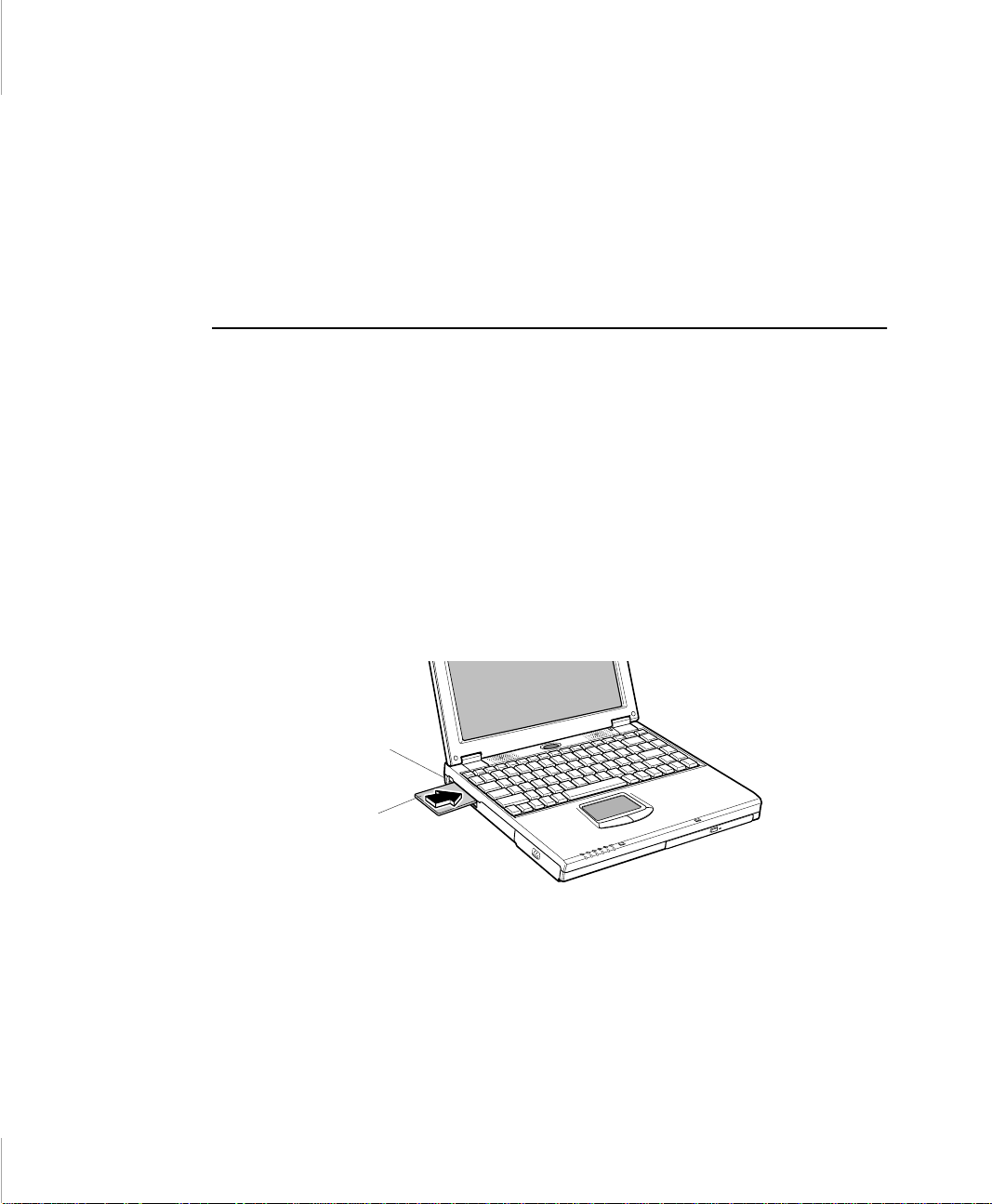
• Do not drop, bend, flex, or crush cards when handling.
• Keep dust, magnets, and static electricity away from PC Cards.
• When a card is not in use, carry it in its protective carrying case.
• Some PC Cards include cabl es that extend from the back of the cards. Be
careful not to be nd or put excessive strain on these cables.
Using PC Cards
You can install PC Cards w h il e th e comput er is o n.
To insert a PC Card into a slot:
1. Push the slot door with a PC Card.
2. Align the card with a slot and inse rt the card into the slot unti l it locks in pla ce
(Figure 21).
The eject button for the card slot operates in two steps.
To remove a PC Card:
1. push the eject button once to pop it outward.
2. Push the eject button ag ain, then the card will be ejected.
Eject button
PC Card
Figure 21. Inserting a PC Card
Windows 98
Windows 98 automatically assigns computer res ources (such as communication
ports and memory addresses) to a PC Car d install ed in your compute r. For further
Work ing with PC Cards 71
Page 55

information on configuring a PC Card in Wi ndows 98, see the index ent ry PC car d
in the Windows Help. Windows 9 8 als o handl es po wer managem ent for PC Ca rds.
To remove a PC Card from your computer if your operating s ystem is Windows
98:
Use the following procedures to remove PC Cards, or you
may lose data that is being stored to a card.
1. Click the PC Card icon on the taskbar.
2. Select the name of the card you wa nt to rem ove, a nd then cl ick t he St op bu tto n.
3. Push the card eject button on t he si de of th e PC C ard sl ot when prompte d t o do
so.
4. Pull the card out of the PC Card slot.
Windows NT
Systemsoft Card Wizard is ship ped with this notebook comput er that use Windows
NT as the oper ati n g sy stem . When yo u ins ta ll a PC Car d , Car dWiza rd at tempt s to
configure it automatically. If Card Wizard successfully assigns system resources
to your card, the comput er bee ps twice.
If CardWizard cannot automatically configure you r PC Card, the computer beeps
once and a message appears telling you that the card has not been configured. Cl ick
the Wizard butto n on the CardWiz ard window. Ca rdWizard then ana lyzes why the
card was not configured and fixes the proble m or gives you informati on to help fix
the problem.
72 User’s Manual
CardWizard works with the PowerProfiler program to manage PC Cards when the
computer enters or re sumes from rest m ode. CardWizard gives you inst ruction s to
prevent loss of data before the computer enters re st mode o r may stop the com puter
from entering rest mode. ATA and modem cards can enter rest mode.
Follow these guidelines when using PC Cards with CardWizard:
• Some of LAN (local-area network) cards can be inserted while the computer
is on but should be removed only when the system is turned off.
• SCSI cards should be inserted at startup to enable Windows NT to find the
device attached to the SCSI card. SCSI cards can b e r emoved when th e
computer is turned off. If you restart your computer without the SCSI card
Page 56

install ed, a message may appear te lling you that a servic e did not start. You
can ignore this message.
• Modem and ATA cards can be inserte d and re moved while the computer is
on.
Before you remove a modem or ATA card from your
computer, stop the card through the CardWizard program or
you may lose data.
To stop and remove a PC Card from your computer:
1. In the SystemSoft CardWizard screen, click wit h the right mouse button on the
name of the card you want to remove.
2. Click Stop in the Actions menu. A red stop sign appears on the main screen
when the card is stopped.
3. Click OK.
4. Push the card eject button on the side of the PC Card slot.
5. Pull the card out of the slot compartm ent.
For more information on using the Card Wizard program, see the CardWizard
Help.
Work ing with PC Cards 73
Page 57

Upgrading Memory
You can increase system memory by installi ng optional memory module s. You
can install a 16, 32, 64, 128, or 256 MB module.
To avoid possible system problems, use only approved
memory modules in your computer. U se the only one type
memory module, either EDO or SDRAM.
Before You Install Memory
To prevent personal injury and damage to the equipment,
follow the precautions listed here before installing a memory
module.
Take the following precautions when installing a memory module:
• Before you remove the memory module compa r tment door, turn off the
computer, unplug the power cord, and remove the battery. Also, disconnec t
any periphera l devices.
• Before handling a memory module, discharge any static electricity by
touching a grounded surface or using a grounding wrist strap.
• Do not insert objects with conductive mate rial, such as metal screwdrivers or
graphite pencils, into the memory-module compartment.
• Be careful in handling the metal plate of the memory door.
74 User’s Manual
Installing a Memory Module
Handle a memory module carefully. Hold them only by the
edges.
To install a memory module:
1. Turn the computer over so that the bottom faces up.
Page 58
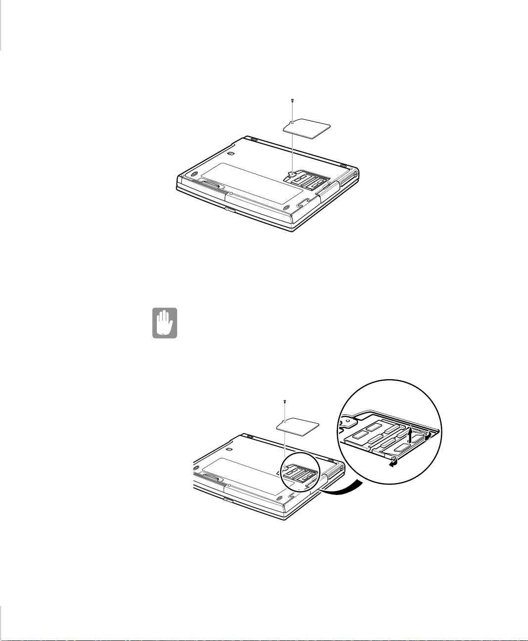
2. Using a screwdriver, remove the screw that holds the memory-module
compartment door in place (Figure 22).
Figure 22. Removing the Memory Module Compartment Door
3. Grasp the edge of the door and pull the door off the chassis.
4. Remove installed modules if necessary:
When removing modules, pull on the plastic portion of the
connector slots tabs only. Do not pull on the metal part of the
tabs, or you may damage th e tab s.
a. Pull the tabs on the connector slot outward sligh tly, until the edge of
the memory module pops up (Figure 23).
Figure 23. Removing a Memory Module
Tab
Tab
Upgrad in g Memory 75
Page 59
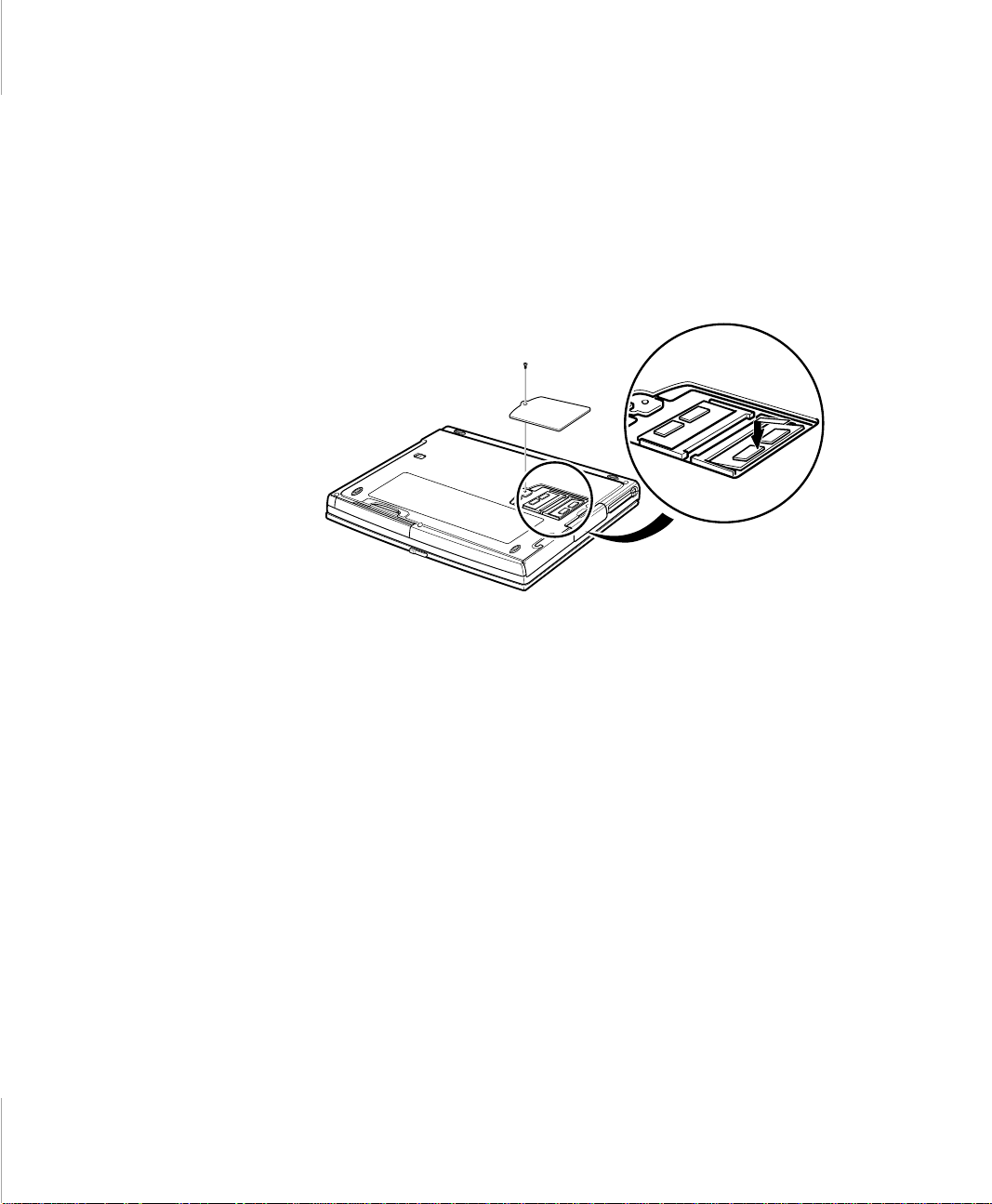
b. Hold the memory module by the edges and pull it forward out of the
compartment.
5. Align the connector on the memory module with the connector of the slot.
6. Push the memory module into the slot at a sli ght angle unt il the connect ors are
fully engaged (Figure 24).
7. Push down on the edge of the memory module until the module snaps into
place.
Figure 24. Insta lling a Memory Module
8. Align the memory module compartment door with the compart ment and push
the door down until it snaps into place.
76 User’s Manual
9. Reinstall the screw you removed in step 2.
10. Turn on the comp u ter and per form a complete POST to check the memory
integrity.
Page 60

About Drivers and System Resources
This section gives you basic information about drivers and system IRQs.
Drivers
A driver is a program that enables the operating system to work with a hardware
device. Your compute r includes drivers for the a udio, video, infrared , touchpad,
keyboard, CD-ROM drive, hard drive , floppy drive, and PC Card controller . When
you add a device to your computer, such as a pri nter, you install a driver for that
device. Different drivers are used by different operating systems.
IRQs
Most of the devices in your computer or connected to your compu ter need their
own IRQ (interrupt reque st li ne). T he IRQ is a hardwa re line that a devic e can us e
to send signa ls to t he microproc essor. When the device ne eds the mi croprocessor’s
service, the device sends an interrupt reque st signal to the microproce ssor.
The number of IRQs available for any computer is limited by in dustry standards.
Because it ships with numerous feature s, this com puter us es most of the availa ble
IRQs. If you add another devic e to your computer, you may need to disable an
existing device to free up an IRQ for the new devi ce. IRQ resources are of
particular concern when the computer is attached to a dockin g device.
The default IRQ set tings that are used by your comp uter are listed in Tabl e 9 an d
Table 10.
Table 9. IRQs, Windows 98 Systems
IRQ Component
0 System timer
1 Keyboard
2 Internal Controller
3 IrDA Port
4 COM 1, COM 3
About Drivers and System Resources 77
Page 61

IRQ Component
5 Audio/USB
6 Floppy controller
7 LPT1 (parall el port)
8 CMOS/Clock
9 ACPI bus SCI IRQ
10 Reserved
11 CardBu s/Mod em
12 Touchpad, PS/2 mouse
13 Nume ric data processor
14 IDE 1 (hard drive)
15 IDE 2 (CD-ROM drive)
Table 10. IRQs, Windows NT Systems
IRQ Component
0 System timer
1 Keyboard
2 Internal Controller
3 COM 2, COM 4
4 COM 1, COM 3
5 Audio/USB
6 Floppy controller
7 LPT1 (parallel port )
8 CMOS/Clock
9 Available
10 Availa ble
11 CardBus/ Mo dem
12 Touchpad, PS/2 mouse
13 Numeric data processor
14 IDE 1 (hard drive)
15 IDE 2 (CD-ROM drive)
78 User’s Manual
Page 62

In Windows 98, you c an configure a device so t hat the de vice is disabled whe n you
connect your c omputer to a docking station but enabled when the computer is not
connected to the docking station. With thi s c onfiguration, an IRQ is avai lable for
a peripheral devic e that you c onnect t o the docki ng station. See your Windows 98
manual for more information.
About Drivers and System Resources 79
Page 63

Specifications
Table 11 gives the specifications for 3-spindle type computer.
Table 11. System Specifications (3-spindle type comput er)
Dimension
Width 12.2 in (31.0 cm)
Height 1.56 in (3.97 cm)
Depth 9.96 in (25.2 cm)
Weight (with Li-Ion battery & 13.3 in
TFT LCD & weight saver)
LCD viewing area (13.3 TFT) 10.6 x 8.0 in (270.3 x 202.8 mm )
LCD viewing area (14.1 TFT) 11.2 x 8.4 in (285.7 x 214.3 mm)
Environment
Ambient temperature, operating 50o–90o F (10o–32oC)
Ambient temperature, storage 23o–104o F (-5o–40o C)
Relative humid ity (noncondensing) ,
operating
Relative humid ity (noncondensing) ,
storage
Altitude, operating 0 to 8,000 ft (0 to 2,348 m)
Altitude, storage 0 to 40,000 ft (0 to 12,192 m)
Shock, operating 10 G for 11 ms half sine
Shock, nonoperating 60 G for 11 ms half sine
Litume-Ion Smart Battery
5.84 lb (2656 g)
20–80%
5–90%
Weight 0.92 lb (420 g)
Nominal open circ uit voltage 11.1 VDC
Capacity, typica l 5100 mAhr, 56.6whr
Charging time, approximate, with
computer turned off
Charging time, approximate, with
computer turned on
3.0 hr (Li-Ion)
5.0 hr (Li-Ion)
Specifications 83
Page 64

Average battery life, with no power
management enabled
External AC Adapter
Operating voltage 100~120 VAC to 200~240 VAC
Line frequency 50-60 Hz
Input curren t 1.5 A 100 V ~ 0.8 A 240 V
Output current 3.15 A
Output voltage 19.0 VDC
3.0 hr
Table 12 gives the specifications for 2-spindle type computer.
Table 12. System Specifications (2-spindle type comput er)
Dimension
Width 12.2 in (31.0 cm)
Height 1.3 in (3.29 cm)
Depth 9.96 in (25.2 cm)
Weight (with Li-Ion battery & 13.3 in
TFT LCD & weight saver)
LCD viewing area (13.3 TFT) 10.6 x 8.0 in (270.3 x 202.8 mm )
LCD viewing area (14.1 TFT) 11.2 x 8.4 in (285.7 x 214.3 mm)
Environment
5.26 lb (2393 g)
84 User’s Manual
Ambient temperature, operating 50o–90o F (10o–32oC)
Ambient temperature, storage 23o–104o F (-5o–40o C)
Relative humid ity (noncondensing) ,
operating
Relative humid ity (noncondensing) ,
storage
Altitude, operating 0 to 8,000 ft (0 to 2,348 m)
Altitude, storage 0 to 40,000 ft (0 to 12,192 m)
Shock, operating 10 G for 11 ms half sine
Shock, nonoperating 60 G for 11 ms half sine
20–80%
5–90%
Page 65

Litume-Ion Smart Battery
Weight 0.92 lb (420 g)
Nominal open circ uit voltage 11.1 VDC
Capacity, typica l 5100 mAhr, 56.6whr
Charging time, approximate, with
3.0 hr (Li-Ion)
computer turned off
Charging time, approximate, with
5.0 hr (Li-Ion)
computer turned on
Average battery life, with no power
3.0 hr
management enabled
External AC Adapter
Operating voltage 100~120 VAC to 200~240 VAC
Line frequency 50-60 Hz
Input curren t 1.5 A 100 V ~ 0.8 A 240 V
Output current 3.15 A
Output voltage 19.0 VDC
Specifications 85
 Loading...