

Page 1

等离子电视
底板: F76A(P_FHD)_C7XXX_C6XXX
型号: PS63C7000YFXXZ
维
等离子电视
PS63C7000YF
涉及 GSPN 维修手册(翻阅封底)获取更多信息。
修
手 册
1. 注意事项
2. 产品规格
3. 拆卸和重新组装
4. 故障排除
5. 分解图和零件清单
6. 接线图
目录
Page 2

GSPN (全球维修合作网络)
国家 网站
北美
拉丁美洲
CIS cis.samsungportal.com
欧洲
中国
亚洲
中东&非洲
service.samsungportal.com
latin.samsungportal.com
europe.samsungportal.com
china.samsungportal.com
asia.samsungportal.com
mea.samsungportal.com
本维修手册归三星电子有限公司所有。
未经授权使用该手册可能受到适用的国际和/或国
内法律的惩罚。
©三星电子有限公司。2010 年 7 月
中国印刷
AA82-06633A
Page 3

目录表
1.注意事项
1-1 安全注意事项.................................................................................................................... 1-1
1-2 维修注意事项.................................................................................................................... 1-3
1-3 静电敏感器件注意事项 ..................................................................................................... 1-4
1-4 安装注意事项.................................................................................................................... 1-5
2.产品规格
2-1 产品特点........................................................................................................................... 2-1
2-2 规格分析......................................................................................................................... 2-20
2-3 工厂选项详情.................................................................................................................. 2-24
2-4 附件................................................................................................................................ 2-26
3.拆卸和重新组装
3-1 整体拆卸和重新组装......................................................................................................... 3-1
4.故障排除
4-1 错误模式检查点 ........................................................................................................... 4-1
4-2 调节................................................................................................................................ 4-13
4-3 升级................................................................................................................................ 4-33
5.分解图和零件清单
5-1 分解图 .............................................................................................................................. 5-1
5-2 维修项目........................................................................................................................... 5-3
6.接线图
6-1 总体接线.......................................................................................................................... 6-1
Page 4

Precaution
1. Precaution
To avoid possible damage, electric shocks or exposure to radiation, follow the instructions below with regard to
safety, installation, service and ESD.
1-1 Safety Precautions
1. Make sure all protective devices are properly installed including non-metallic handles and compartment covers
when installing or re-installing the chassis or chassis assemblies.
Make sure that no gaps exist between the cabinets for children to insert their fingers in to prevent children from
2.
receiving electric shocks. Gaps mentioned above include ventilation holes of a too great magnitude between
the PDP module and the cabinet mask, and the improper installation of the rear cabinet.
Errors may occur when the resistance is below 1.0MΩ or over 5.2MΩ. In these cases, make sure that the
device is repaired before sending it back to the customer.
4. Check for Electricity Leakage (AC Leakage Test)
Warning: Do not use an insulated transformer for
checking the leakage. Use only those
current leakage testers or mirroring systems
that comply with ANSIC 101.1 and the
Underwriter Laboratory’s specifications
(UL1410, 59.7).
DEVICE
UNDER
TEST
EXPOSED METAL
2-WIRE CORD
ALSO TEST WITH
PLUG REVERSED
(USING AC
ADAPTER PLUG
AS REQUIRED)
LEAKAGE
CURRENT
TESTER
TEST ALL
SURFACES
(READING
SHOULD NOT BE
ABOVE 0.5mA)
EARTH
GROUND
<Fig. 1-1 AC Leakage Test>
4. A high voltage is maintained within the specified limits using safety parts, calibration and tolerances. When
voltage exceeds the specified limits, check each special part.
5. Warning for Engineering Changes:
Never make any changes or additions to the circuit design or the internal part for this product.
Ex: Do not add any audio or video accessory connectors. This might cause physical damage.
Furthermore, any changes or additions to the original design/engineering will invalidate the warranty.
6. Warning - Hot Chassis:
Some TV chassis are directly connected to one end of the AC power cord for electrical reasons.
Without insulated transformers, the product can only be repaired safely when the chassis is connected to the
earthed end of the AC power source.
To make sure the AC power cord is properly connected, follow the instructions below. Use the voltmeter to
measure the voltage between the chassis and the earthed ground. If the measurement is over 1.0V, unplug the
AC power cord and change the polarity before reinserting it. Measure the voltage between the chassis and the
ground again.
Samsung Electronics 1-1
Page 5

1-2 Samsung Electronics
Precaution
7. Some TV chassis are shipped with an additional secondary grounding system. The secondary system
is adjacent to the AC power line. These two grounding systems are separated in the circuit using an
unbreakable/unchangeable insulation material.
8. When any parts, material or wiring appear overheated or damaged, replace them with new regular ones
immediately. When any damage or overheating is detected, correct this immediately and make a regular check
of possible errors.
9. Check for the original shape of the lead, especially that of the antenna wiring, any sharp edges, the AC power
and the high voltage power. Carefully check if the wiring is too tight, incorrectly placed or loose. Never change
the space between the part and the printed circuit board. Check the AC power cord for possible damages.
Keep the part or the lead away from any heat-emitting materials.
10. Safety Indication:
Some electrical circuits or device related materials require special attention to their safety features, which
cannot be viewed by the naked eye. If an original part is replaced with another irregular one, the safety or
protective features will be lost even if the new one has a higher voltage or more watts.
Critical safety parts should be bracketed with (
, ). Use only regular parts for replacements (in particular,
flame resistance and dielectric strength specifications). Irregular parts or materials may cause electric shock or
fire.
Page 6

Precaution
1-2 Servicing Precautions
Warning 1: First carefully read the “Safety Instruction” in this service manual.
When there is a conflict between the service and the safety instructions, follow the safety instruction
at all times.
Warning 2: Any electrolytic capacitor with the wrong polarity will explode.
1. The service instructions are printed on the cabinet, and should be followed by any service personnel.
2. Make sure to unplug the AC power cord from the power source before starting any repairs.
(a) Remove or re-install parts or assemblies.
(b) Disconnect the electric plug or connector, if any.
(c) Connect the test part in parallel with the electrolytic capacitor.
3. Some parts are placed at a higher position than the printed board. Insulated tubes or tapes are used for this
purpose. The internal wiring is clamped using buckles to avoid contact with heat emitting parts. These parts
are installed back to their original position.
4. After the repair, make sure to check if the screws, parts or cables are properly installed. Make sure no damage
is caused to the repaired part and its surroundings.
5. Check for insulation between the blade of the AC plug and that of any conductive materials (i.e. the metal
panel, input terminal, earphone jack, etc).
6. Insulation Check Process:
Unplug the power cord from the AC source and turn the switch on. Connect the insulating resistance meter
(500V) to the AC plug blade. The insulating resistance between the blade of the AC plug and that of the
conductive material should be more than 1MΩ.
7. Any B+ interlock should not be damaged.
If the metal heat sink is not properly installed, no connection to the AC power should be made.
8. Make sure the grounding lead of the tester is connected to the chassis ground before connecting to the
positive lead. The ground lead of the tester should be removed last.
9. Beware of risks of any current leakage coming into contact with the high-capacity capacitor.
10. The sharp edges of the metal material may cause physical damage, so protect yourself by wearing gloves
during the repair.
11. Due to the nature of plasma display panels, partial after-images may appear if a still picture is displayed on the
screen for a long period of time.
This is caused by brightness deterioration due to the storage effect of the panel, and to prevent this from
happening, we recommend that the brightness and contrast are reduced.
(e.g.) Contrast: 25, Brightness: 50
Samsung Electronics 1-3
Page 7

1-4 Samsung Electronics
Precaution
1-3 Static Electricity Precautions
1. Some semi-conductive (“solid state”) devices are vulnerable to static electricity. These devices are known as
ESD. ESD includes the integrated circuit and the field effect transistor. To avoid any materials damage from
electrostatic shock, follow the instructions described below.
2. Remove any static electricity from your body by connecting the earth ground before handling any semi-
conductive parts or assemblies. Alternatively, wear a dischargeable wrist-belt.
(Make sure to remove any static electricity before connecting the power source - this is a safety instruction for
avoiding electric shock)
3. Remove the ESD assembly and place it on a conductive surface such as aluminum foil to prevent
accumulating static electricity.
4. Do not use any Freon-based chemicals. Such chemicals will generate static electricity that causes damage to
the ESD.
5. Use only grounded-tip irons for soldering purposes.
6. Use only anti-static solder removal devices.
Most solder removal devices do not support an anti-static feature. A solder removal device without an anti-
static feature can store enough static electricity to cause damage to the ESD.
7. Do not remove the ESD from the protective box until the replacement is ready. Most ESD replacements are
covered with lead, which will cause a short to the entire unit due to the conductive foam, aluminum foil or other
conductive materials.
8. Remove the protective material from the ESD replacement lead immediately after connecting it to the chassis
or circuit assembly.
9. Take extreme caution in handling any uncovered ESD replacements. Actions such as brushing clothes or
lifting your leg from the carpet floor can generate enough static electricity to damage the ESD.
CAUTION
These servicing instructions are for use by
qualified service personnel only.
To reduce the risk of electric shock do not perform
any servicing other than that contained in the
operating instructions unless you are qualified to
do so.
Page 8

Precaution
1-4 Installation Precautions
1. For safety reasons a minimum of two people are required to
carry this product.
2. Keep the power cord away from any heat emitting devices, as a melted covering may cause fire or electric
shock.
3. Do not place the product in areas with poor ventilation such as a bookshelf or closet. The increased internal
temperature may cause fire.
4. Bend the external antenna cable when connecting it to the product. This is a measure to protect it from being
exposed to moisture. Otherwise, it may cause a fire or electric shock.
5. Make sure to turn the power off and unplug the power cord from the outlet before repositioning the product.
Also check the antenna cable or the external connectors if they are fully unplugged. Damage to the cord may
cause fire or electric shock.
6. Keep the antenna far away from any high-voltage cables and install it firmly. Contact with the high-voltage
cable or the antenna falling over may cause fire or electric shock.
7. When connecting the RF antenna, check for a DTV receiving system and install a separate DTV reception
antenna for areas with no DTV signal.
8. When installing the product, leave enough space (4”) between the product and the wall for ventilation
purposes. A rise in temperature within the product may cause fire.
9. When moving a PDP with removable speakers, detach the speakers first before moving the main body.
Moving the PDP main body without separating the speakers may cause the speakers to detach, possibly
causing damage or injury.
Samsung Electronics 1-5
Page 9

MEMO
1-6 Samsung Electronics
Page 10
2. Product Specification
2-1 Product Feature
New features
This function enables you to easily view the photos or moving pictures without connecting
Media Play
any other devices such as BD player, only with connecting USB device including the
contents.
Product Specification
All share
Internet@TV
PVR
This function enables users to connect TV, mobile phones and other devices which are
compatible through network.
This function enables users to more easily contact to internet server by only clicking the
icon revealing on the screen.
Recoding function, timeshift function, this function enables users to record contents users
want to review.
Samsung Electronics 2-1
Page 11
Product Specification
Europe Features
Block Specification Major IC
RF Digital/Analog (DTV Built In)
PDP Module
Power
Video
Sound SRS TruSuround HD, Dolby Digital STA369BWS
Cabinet C7000, C7790 Design
Australia Features
Block Specification Major IC
RF Digital/Analog (DTV Built In)
50” Samsung SDI US2 50” FHD
63”
Samsung electro mechanics SMPS
Danam electronics SMPS 110V ~ 220V Free volt
DVB-T/C/(S), PAL, SECAM, NT4.4.3
HDMI
DNIe
Component, PC
Samsung SDI US2 63” FHD
DVB/HALF-NIM
TUNER
Arsenal WW, Valencia
DVB/HALF-NIM
TUNER
50” Samsung SDI US2 50” FHD
PDP Module
Power
Video
Sound SRS TruSuround HD, Dolby Digital STA369BWS
Cabinet C7000 Design
Danam electronics SMPS 110V ~ 220V Free volt
58” Samsung SDI US2 58” FHD
63” Samsung SDI US2 63” FHD
Samsung electro mechanics SMPS
DVB-T/C/(S), PAL, SECAM, NT4.4.3
HDMI
DNIe
Component, PC
Arsenal WW, Valencia
2-2 Samsung Electronics
Page 12

Europe Specification
Product Specification
Model
Dimensions (WxHxD)
Weight
Voltage AC 100~240V, 60Hz 550W AC 100~240V, 60Hz 670W
PC Resolution
Screen Size
ANTENNA Input
VIDEO Input
PS50C7XXX
PS50C6XXX
1212 X 808 X 290 mm (with stand)
1212 X 734.5 X 36.8 mm (without stand)
29.5kg (with Stand)
24.5kg (without stand)
1920(H) X 1080(V)
50 inches (16:9) 63 inches (16:9)
ANT - AIR/CABLE IN
75Ω unbalanced
AV1
COMPONENT - 480i/480p/720p/1080i/1080p
PC
HDMI1(DVI Compatible) - 480p/720p/1080i/1080p
HDMI2 - 480p/720p/1080i/1080p
HDMI3 - 480p/720p/1080i/1080p
HDMI4 - 480p/720p/1080i/1080p
PS63C7XXX
1492.5 X 956.8 X 342 mm (with stand)
1292.5 X 908.5 X 35.9 mm (without Stand)
44.6kg (with Stand)
38kg (without stand)
AUDIO Input
Audio Output
Speaker Output
New Features
AV
COMPONENT - 480i/480p/720p/1080i/1080p
PC
DVI
AUDIO (L/R)
10W + 10W 15W + 15W
Anynet+, 3D, Media Play, PVR, Internet@TV, Wireless Remote Control,
Wireless Dongle, All Share
Samsung Electronics 2-3
Page 13
Product Specification
Australia Specification
Model
Dimensions (WxHxD)
Weight
Voltage AC 100~240V, 60Hz
PC Resolution
Screen Size
ANTENNA Input
VIDEO Input
PS50C7XXX
PS50C6XXX
1212 X 808 X 290 mm
(with stand)
1212 X 734.5 X 36.8 mm
(without stand)
29.5kg (with Stand)
24.5kg (without stand)
PS58C7XXX PS63C7XXX
1228 X 917 X 338 mm
(with stand)
1288 X 849 X 36.8 mm
(without stand)
40kg (with Stand)
33.3kg (without stand)
1492.5 X 956.8 X 342 mm
(with stand)
1292.5 X 908.5 X 35.9 mm
(without Stand)
44.6kg (with Stand)
38kg (without stand)
1920(H) X 1080(V)
50 inches (16:9) 58 inches (16:9) 63 inches (16:9)
ANT - AIR+CABLE, AIR+CABLE+SATELLITE
75Ω unbalanced
AV1
COMPONENT - 480i/480p/720p/1080i/1080p
PC
HDMI1(DVI Compatible) - 480p/720p/1080i/1080p
HDMI2 - 480p/720p/1080i/1080p
HDMI3 - 480p/720p/1080i/1080p
HDMI4 - 480p/720p/1080i/1080p
AUDIO Input
Audio Output
Speaker Output
New Features
AV
COMPONENT - 480i/480p/720p/1080i/1080p
PC
DVI
AUDIO (L/R)
10W + 10W 15W + 15W 15W + 15W
Anynet+, 3D, Media Play, PVR, Internet@TV, Wireless Remote Control,
Wireless Dongle, All Share
2-4 Samsung Electronics
Page 14

Product Specification
O 3D Mode: Select the 3D input format.
If you want to feel the 3D effect fully, please wear
the 3D Active Glasses first, and then select 3D
mode from the list below that provides the best
3D viewing experience.
3D Mode Operation
Off Turns the 3D function off.
2D → 3D
Changes a 2D image to 3D.
Side by Side
Displays two images next to
each other.
Top & Bottom
Displays one image above
another.
Line by Line
Displays the images for the left
and right eye alternately in rows.
Vertical Stripe
Displays the images for the
left and right eye alternately in
columns.
Checker
Board
Displays the images for the
left and right eye alternately in
pixels.
Frequency
Displays the images for the
left and right eye alternately in
frames.
“Side by Side” and “Top & Bottom” are available
when the resolution is 720p, 1080i and 1080p
in DTV, HDMI and USB mode or set to PC
connecting through HDMI/DVI cable.
“Vertical Strip”, “Line by Line” and “Checker
Board” are available when the resolution is set to
PC connecting through HDMI/DVI cable.
“Frequency” displays the frequency (60Hz only)
when the resolution is set to PC.
O 3D Auto View (Off / On): If 3D Auto View is set to On,
a “Side-By-Side” format HDMI signal with one of the
resolutions below is automatically switched to 3D. Here,
correct 3D information must be sent from the HDMI 1.3
transmitter.
If a 3D failure occurs due to a 3D information error,
set 3D Auto View to Off and manually select a
3D Mode using the 3D button or corresponding
menu.
Support resolution (16:9 only)
Resolution Frequency (Hz)
1280 x 720p 50 / 60 Hz
1920 x 1080i 50 / 60 Hz
1920 x 1080p 24 / 30 / 50 / 60 Hz
Resolution supported for HDMI PC mode
The resolution for HDMI PC mode is optimized to 1920 x
1080 input.
An input resolution other than 1920 x 1080 may not be
displayed properly in 3D display or full screen mode.
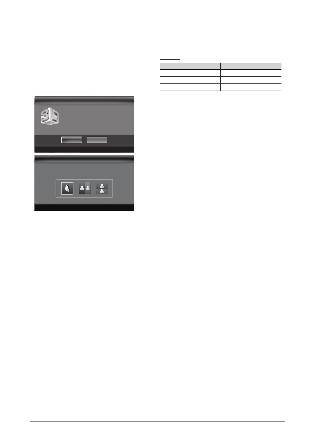
How to watch the 3D image
3D
OK
To watch in 3D, wear 3D glasses and
press the power button on the glasses.
Cancel
U
Move
E
Enter
e
Exit
3D3D
O 3D Mode: Select the 3D input format.
If you want to feel the 3D effect fully, please wear
the 3D Active Glasses first, and then select 3D
mode from the list below that provides the best
3D viewing experience.
3D Mode Operation
Off Turns the 3D function off.
2D → 3D
Changes a 2D image to 3D.
Side by Side
Displays two images next to
each other.
Top & Bottom
Displays one image above
another.
Line by Line
Displays the images for the left
and right eye alternately in rows.
Vertical Stripe
Displays the images for the
left and right eye alternately in
columns.
Checker
Board
Displays the images for the
left and right eye alternately in
pixels.
Frequency
Displays the images for the
left and right eye alternately in
frames.
“Side by Side” and “Top & Bottom” are available
when the resolution is 720p, 1080i and 1080p
in DTV, HDMI and USB mode or set to PC
connecting through HDMI/DVI cable.
“Vertical Strip”, “Line by Line” and “Checker
Board” are available when the resolution is set to
PC connecting through HDMI/DVI cable.
“Frequency” displays the frequency (60Hz only)
when the resolution is set to PC.
O 3D → 2D (Off / On): Displays the image for the left eye
only.
This function is deactivated when 3D Mode set to
“2D → 3D” or Off.
O Depth: Adjusts focus / depth in “2D → 3D” mode.
This function is only activated when the 3D Mode
is “2D → 3D”.
O Picture Correction: Adjusts the images for the left and
right eye.
O 3D Auto View (Off / On): If 3D Auto View is set to On,
a “Side-By-Side” format HDMI signal with one of the
resolutions below is automatically switched to 3D. Here,
correct 3D information must be sent from the HDMI 1.3
transmitter.
If a 3D failure occurs due to a 3D information error,
set 3D Auto View to Off and manually select a
3D Mode using the 3D button or corresponding
menu.
Support resolution (16:9 only)
Resolution Frequency (Hz)
1280 x 720p 50 / 60 Hz
1920 x 1080i 50 / 60 Hz
1920 x 1080p 24 / 30 / 50 / 60 Hz
Resolution supported for HDMI PC mode
The resolution for HDMI PC mode is optimized to 1920 x
1080 input.
An input resolution other than 1920 x 1080 may not be
displayed properly in 3D display or full screen mode.
How to watch the 3D image
1. Press the CONTENT button, then the Content View
menu will appear.
2. Press the ◄ or ► button, then select 3D.
3D
OK
To watch in 3D, wear 3D glasses and
press the power button on the glasses.
Cancel
U
Move
E
Enter
e
Exit
3D3D
Using the LEFT / RIGHT keys on the remote control,
select the icon suitable for the picture on screen.
Using the LEFT / RIGHT keys on the remote control,
select the icon suitable for the picture on screen.
U
Move
E
Enter
e
Exit
U
Move
E
Enter
e
Exit
O 3D Auto View (Off / On): If 3D Auto View is set to On,
a “Side-By-Side” format HDMI signal with one of the
resolutions below is automatically switched to 3D. Here,
correct 3D information must be sent from the HDMI 1.3
transmitter.
If a 3D failure occurs due to a 3D information error,
set 3D Auto View to Off and manually select a
3D Mode using the 3D button or corresponding
menu.
Support resolution (16:9 only)
Resolution Frequency (Hz)
1280 x 720p 50 / 60 Hz
1920 x 1080i 50 / 60 Hz
1920 x 1080p 24 / 30 / 50 / 60 Hz
3D
3D
3D emitter
2-1-1 New Features explanation
3D
This exciting new feature enables you to view 3D content. In order to fully enjoy this feature, you
must purchase a pair of Samsung 3D Active Glasses (SSG-2100AB, SSG-2200AR, SSG-2200KR)
to view 3D video.
Samsung 3D Active Glasses are sold separately. For more detailed purchasing information,
contact the retailer where you purchased this TV.
✎ If there is any obstacle between the emitter and 3D Active
Glasses, the proper 3D effect may not be obtained.
Samsung Electronics 2-5
Page 15
Product Specification
O 3D Auto View (Off / On): If 3D Auto View is set to On,
a “Side-By-Side” format HDMI signal with one of the
resolutions below is automatically switched to 3D. Here,
correct 3D information must be sent from the HDMI 1.3
transmitter.
If a 3D failure occurs due to a 3D information error,
set 3D Auto View to Off and manually select a
3D Mode using the 3D button or corresponding
menu.
Support resolution (16:9 only)
Resolution Frequency (Hz)
1280 x 720p 50 / 60 Hz
1920 x 1080i 50 / 60 Hz
1920 x 1080p 24 / 30 / 50 / 60 Hz
Resolution supported for HDMI PC mode
The resolution for HDMI PC mode is optimized to 1920 x
1080 input.
An input resolution other than 1920 x 1080 may not be
displayed properly in 3D display or full screen mode.
How to watch the 3D image
1. Press the CONTENT button, then the Content View
menu will appear.
2. Press the ◄ or ► button, then select 3D.
To watch in 3D, wear 3D Active Glasses and press the
power button on the glasses.
3. Select OK, then press the ENTERE button.
4. Using the ◄ or ► buttons on your remote control,
selects the 3D Mode of the image you want to view.
Some 3D modes may not be available depending
on the format of the image source.
3D
OK
To watch in 3D, wear 3D glasses and
press the power button on the glasses.
Cancel
U
Move
E
Enter
e
Exit
3D3D
Using the LEFT / RIGHT keys on the remote control,
select the icon suitable for the picture on screen.
Using the LEFT / RIGHT keys on the remote control,
select the icon suitable for the picture on screen.
U
Move
E
Enter
e
Exit
U
Move
E
Enter
e
Exit
Supported formats and operating specifications for
HDMI 1.4
Source signal format Standard HDMI 1.4 3D
1920x1080p@24Hz x 2 1920x2205p@24Hz
1280x720p@60Hz x 2 1280x1470p@60Hz
1280x720p@50Hz x 2 1280x1470p@50Hz
The mode is automatically switched to 3D mode for the 3D
video input in one of the formats above.
For the HDMI 1.4@24Hz format, the TV is optimized as
follows:
– Resolution First Display Mode: If Auto Motion
Plus is set to Off, Clear or Standard, you can
watch the video at a high resolution optimized to the
resolution of the source video.
– Judder Reduction Display Mode: When Auto
Motion Plus is set to Smooth or Custom, you can
watch a smooth picture without judder.
2-6 Samsung Electronics
Page 16

Media Play
¦ Connecting a USB Device
1. Turn on your TV.
2. Connect a USB device containing recorded tv, photo, music and/or movie files to
the USB 1 (HDD) or USB 2 jack on the side of the TV.
3. When USB is connected to the TV, popup window appears. Then you can select
Media Play.
¦ Connecting to the PC through network
You can play pictures, music and videos saved on your PC through a network connection in the Media Play mode.
If you use Media Play through saved file on your PC, you should download “PC Share Manager” and users manual from
“www.samsung.com.”
1. For more information on how to configure your network, refer to “Network Connection”.
– You are recommended to locate both TV and PC in same subnet. The first 3 parts of the subnet address of the TV and
the PC IP addresses should be the same and only the last part (the host address) should be changed. (e.g. IP Address:
123.456.789.**)
2. Using a LAN cable, connect between the external modem and the PC onto which the Samsung PC Share Manager
programme will be installed.
– You can connect the TV to the PC directly without connecting it through a Sharer (Router).
Enjoy photos, music and/or movie files saved on
a USB Mass Storage Class (MSC) device and/or
your PC.
MEDIA.P
USB Drive
TV Rear Panel
(HDD)
or
LAN Cable
PC
TV Rear Panel
or
LAN
Samsung
Wireless LAN
Adapter
Wireless IP sharer
External Modem
(ADSL/VDSL/Cable TV)
LAN Cable Modem Cable
LAN Cable
LAN
Adapter
SUM
Change Device
View Devices
E
Enter
R
Return
MediaPlay
Recorded TV
Product Specification
Samsung Electronics 2-7
Page 17
Product Specification
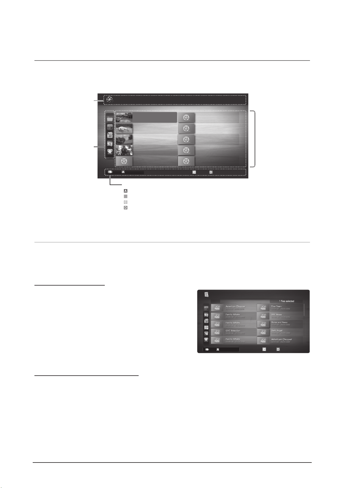
¦ Screen Display
Move to the file you desired using the up/down/right/left buttons and then press the ENTERE or (Play) button. The file is
played.
Supports the View Devices and Home in Media Play homepage.
Recorded TV
To use the recording or Timeshift Mode function, the connected USB device must be available for recording. Device format is
recommended to use USB HDD.
During the Device formatting, do not disconnect the device while formatting is in progress. If you format the device, all
files will be deleted.
Playing Recorded TV Program
1. Press the ◄ or ► button to select Recorded TV, then press
the ENTER
E
button in the Media Play menu.
2. Press the ◄/►/▲/▼ button to select the desired file in the file
list.
3. Press the ENTER
E
button or (Play) button.
– The selected file is displayed on the top with its playing time.
– During playing the recorded TV programme, you can search
using the ◄ and ► button.
Using the Timeshift Mode function
t
If you missed a live broadcast, you can see from the recorded broadcast using this feature.
When the Timeshift Mode is set to Auto, the TV stores the channel you watch currently to record automatically.
When the Timeshift Mode is set to Manual, if you press the
(Play) button, the TV stores the channel from the point of
view you want to record.
Jan.10.2010
Jan.10.2010
Jan.10.2010
Jan.10.2010
Jan.10.2010
Jan.10.2010
Jan.10.2010
Jan.10.2010
Jan.10.2010
Jan.10.2010
/Movie 01.avi 1/1
Movie 01.avi
SUM
Movie 03.avi
Movie 05.avi
Movie 07.avi
Movie 09.avi
Movie 02.avi
Movie 04.avi
Movie 06.avi
Movie 08.avi
Movie 10.avi
Select Sorting
T
Tools
Information:
You can ascertain the selected
file name and the number of files
and page.
Sort List Section:
Displays sorting standard.
Sorting standard is
different depending on the
contents.
Operation Buttons
Red (Change Device): Selects a connected device.
B
Green (Preference): Sets the file preference. (not supported in Basic view)
Yellow (Select): Selects multiple files from file list. Selected files are marked with a symbol.
Blue (Sorting): Selects the sort list.
T
Tools: Displays the option menu.
Using theorµ button, file list can move to next or previous page.
File List Section:
You can confirm the files
and groups that is sorted by
each category.
Videos
Page
Change Device
SUM
Select Sorting
T
Tools
Recorded TV / .../ American Chopper
1/8 Page
05/2010
Change Device
2-8 Samsung Electronics
Page 18
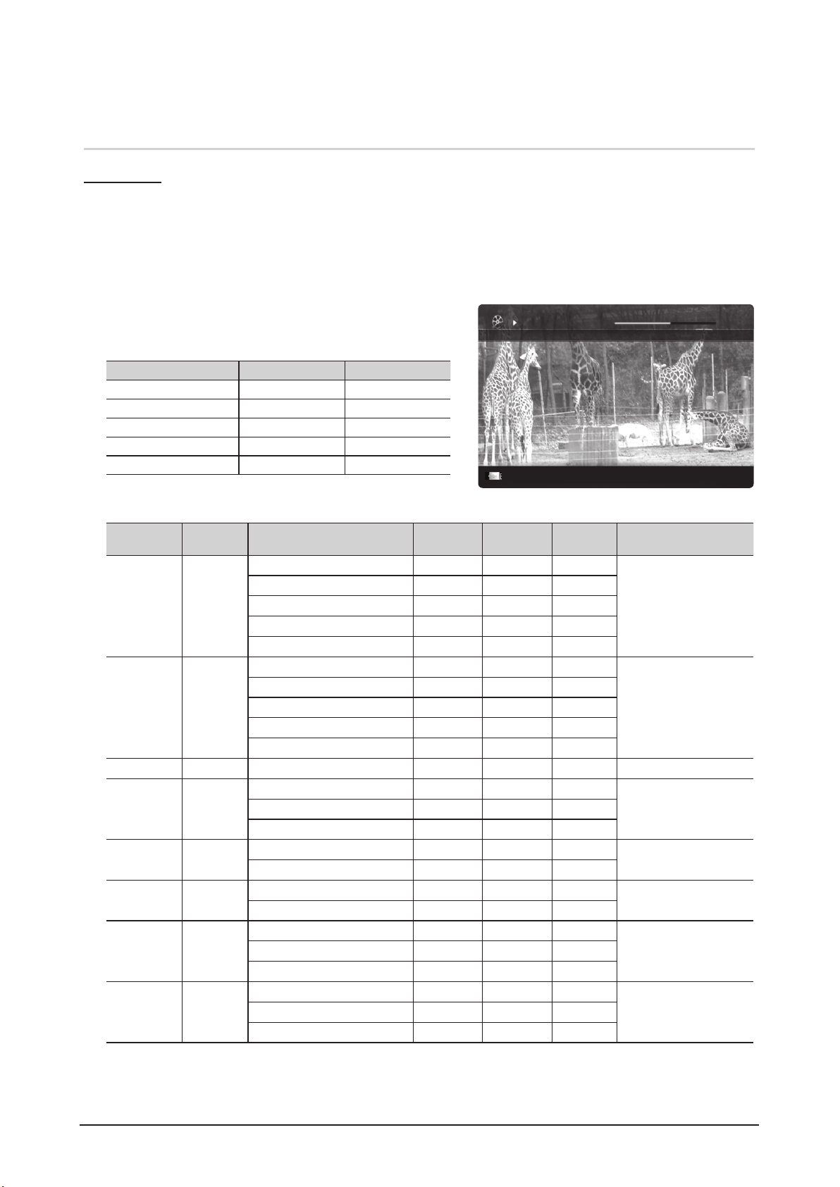
Videos
Playing Video
1. Press the ◄ or ► button to select Videos, then press the ENTER
E
button in the Media Play menu.
2. Press the ◄/►/▲/▼ button to select the desired file in the file list.
3. Press the ENTER
E
button or � (Play) button.
– The selected file is displayed on the top with its playing time.
– If video time information is unknown, play time and progress bar are not displayed.
– During playing the video, you can search using the ◄ and ► button.
In this mode, you can enjoy movie clips contained on a Game,
but you cannot play the Game itself.
Supported Subtitle Formats
Name File extension Format
MPEG-4 time-based text .ttxt XML
SAMI .smi HTML
SubRip .srt string-based
SubViewer .sub string-based
Micro DVD .sub or .txt string-based
Supported Video Formats
File Extension Container Video Codec Resolution
Frame rate
(fps)
Bit rate
(Mbps)
Audio Codec
*.avi
*.mkv
AVI
MKV
Divx 3.11 / 4.x / 5.1 / 6.0 1920x1080 6 ~ 30 8
MP3 / AC3 / LPCM /
ADPCM / DTS Core
XviD 1920x1080 6 ~ 30 8
H.264 BP / MP / HP 1920x1080 6 ~ 30 25
MPEG4 SP / ASP 1920x1080 6 ~ 30 8
Motion JPEG 800x600 6 ~ 30 8
*.asf ASF
Divx 3.11 / 4.x / 5.1 / 6.0 1920x1080 6 ~ 30 8
MP3 / AC3 / LPCM /
ADPCM / WMA
XviD 1920x1080 6 ~ 30 8
H.264 BP / MP / HP 1920x1080 6 ~ 30 25
MPEG4 SP / ASP 1920x1080 6 ~ 30 8
Motion JPEG 800x600 6 ~ 30 8
*.wmv ASF Window Media Video v9 1920x1080 6 ~ 30 25 WMA
*.mp4 MP4
H.264 BP / MP / HP 1920x1080 6 ~ 30 25
MP3 / ADPCM / AACMPEG4 SP / ASP 1920x1080 6 ~ 30 8
XVID 1920x1080 6 ~ 30 8
*.3gp 3GPP
H.264 BP / MP / HP 1920x1080 6 ~ 30 25
ADPCM / AAC / HE-AAC
MPEG4 SP / ASP 1920x1080 6 ~ 30 8
*.vro
VRO
VOB
MPEG1 1920x1080 24 / 25 / 30 30
AC3 / MPEG / LPCM
MPEG2 1920x1080 24 / 25 / 30 30
*.mpg
*.mpeg
PS
MPEG1 1920x1080 24 / 25 / 30 30
AC3 / MPEG / LPCM / AACMPEG2 1920x1080 24 / 25 / 30 30
H.264 1920x1080 6 ~ 30 25
*.ts
*.tp
*.trp
TS
MPEG2 1920x1080 24 / 25 / 30 30
AC3 / AAC / MP3 / DD+ /
HE-AAC
H.264 1920x1080 6 ~ 30 25
VC1 1920x1080 6 ~ 30 25
Movie 01.avi
00:04:03 / 00:07:38 1/1
SUM
E
Chaptering
L
Jump
T
Tools
R
Return
Product Specification
Samsung Electronics 2-9
Page 19

Product Specification
Other Restrictions
NOTE
•
If there are problems with the contents of a codec, the codec will not be supported.
•
If the information for a Container is incorrect and the file is in error, the Container will not be able to play
correctly.
•
Sound or video may not work if the contents have a standard bitrate/frame rate above the compatible Frame/sec
listed in the table above.
•
If the Index Table is in error, the Seek (Jump) function is not supported.
Video Decoder Audio Decoder
• Supports up to H.264, Level 4.1
• H.264 FMO / ASO / RS, VC1 SP / MP / AP L4 and AVCHD are not
supported.
• XVID, MPEG4 SP, ASP :
– Below 1280 x 720: 60 frame max
– Above 1280 x 720: 30 frame max
• GMC 2 over is not supported.
• H.263 is not supported.
• Only Samsung Techwin MJPEG is supported.
• Supports up to WMA 7, 8, 9, STD
• WMA 9 PRO does not support 2 channel excess multi channel or
lossless audio.
• WMA sampling rate 22050Hz mono is not supported.
Playing recorded TV or movie file continuously (Resume Play)
If you exit the playing Recorded TV or Videos function, it can be played later from the point where it was stopped.
If you press the ENTEREbutton (Chaptering) during playing the file, you can explore scene divided into 5 chapters
you want.
1. Select the movie file you want to play continuously by pressing
the ◄ or ► button to select it from the file list section.
2. Press the
(Play) / ENTERE button.
3. Select Play Continuously (Resume Play) by pressing the Blue
button. The Movie will begin to play from where it was stopped.
The Blue button is available when resuming play.
If the Continuous Movie Play Help function is set to On
in the Settings menu, a pop-up message will appear
when you resume play a movie file.
Music
Playing Music
1. Press the ◄ or ► button to select Music, then press the
ENTERE button in the Media Play menu.
2. Press the ◄/►/▲/▼ button to select the desired file in the file
list.
3. Press the ENTER
E
button or (Play) button.
– During playing the music, you can search using the ◄ and ►
button.
–
(REW) and µ (FF) buttons do not function during play.
Only displays the files with MP3 and PCM file extension. Other
file extensions are not displayed, even if they are saved on the
same USB device.
If the sound is strange when playing MP3 files, adjust the Equalizer in the Sound menu. (An over-modulated MP3 file
may cause a sound problem.)
You can create My Playlist selecting the desired music in the file, and can play My Playlist.
3/15
I Love you
Jhon
Music 1
No Singer
Music 2
No Singer
Music 3
No Singer
Music 4
No Singer
Music 5
No Singer
I Love You
Jhon
1st Album
Pop
2010
4.2MB
01:10 / 04:02
SUM
E
Pause
L
Jump
T
Tools
R
Return
Playlist
Movie 01.avi
00:04:03 / 00:07:38 1/1
SUM
Play continuously
E
Chaptering
L
Jump
T
Tools
R
Return
Resumes playing from the last viewed
scene.
Play continuously
2-10 Samsung Electronics
Page 20
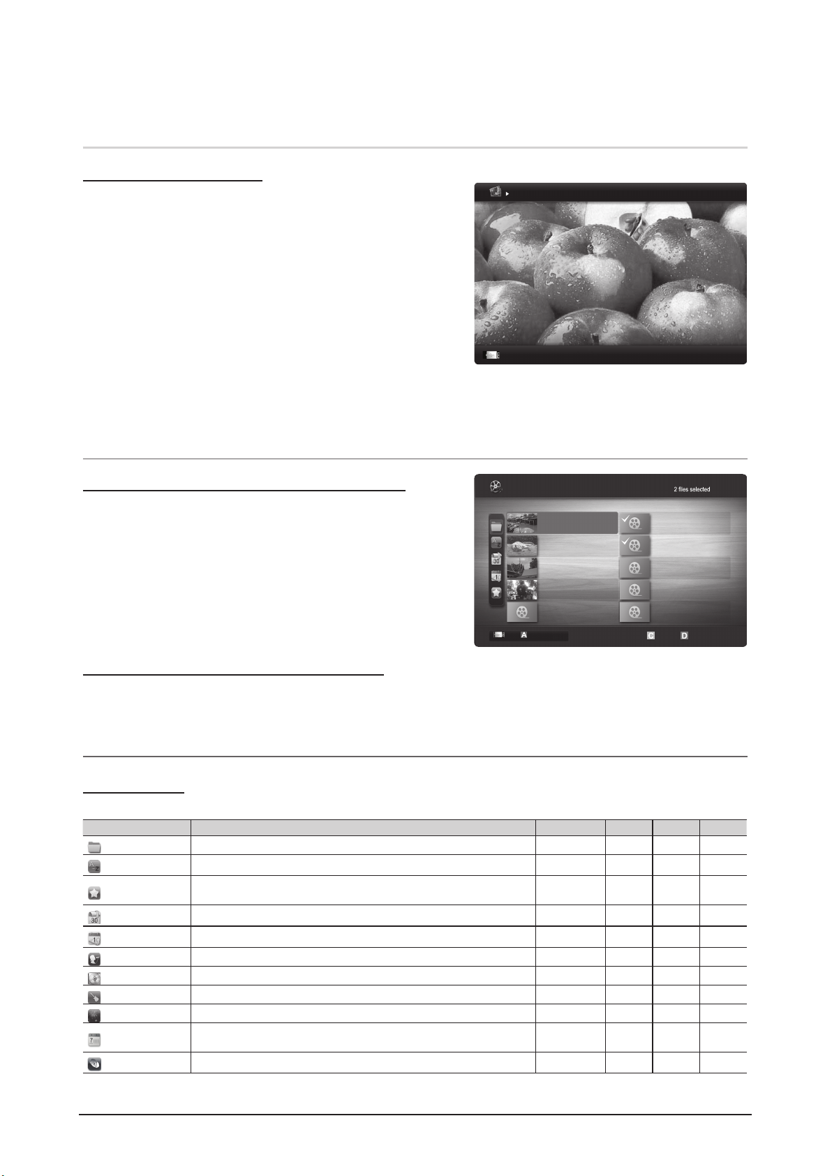
Photos
Viewing a Photo (or Slide Show)
1. Press the ◄ or ► button to select Photos, then press the
ENTER
E
button in the Media Play menu.
2.
Press the ◄/►/▲/▼ button to select the desired file in the file
list.
3. Press the ENTERE button or � (Play) button.
– While a photo list is displayed, press the
�
(Play) /
ENTERE button on the remote control to start slide show.
– All files in the file list section will be displayed in the slide show.
– During the slide show, files are displayed in order from
currently being shown.
Music files can be automatically played during the Slide Show if the Background Music is set to On.
The BGM Mode cannot be changed until the BGM has finished loading.
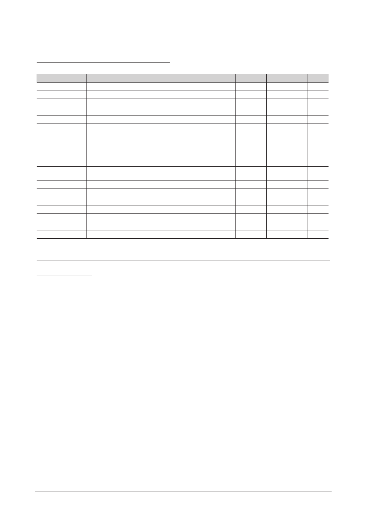
¦ Playing the Multiple Files
Playing the selected recorded TV/video/music/photo files
1. Press the Yellow button in the file list to select the desired file.
2. Repeat the above operation to select multiple files.
NOTE
Thecmark appears to the left of the selected files.
To cancel a selection, press the Yellow button again.
To deselect all selected files, press the TOOLS button
and select Deselect All.
3. Press the TOOLS button and select Play Selected Contents.
Playing the recorded TV/video/music/photo file group
1. While a file list is displayed, move to the any file in desired group.
2. Press the TOOLS button and select Play Current Group.
¦ Media Play Additional Function
Sorting the file list
Press the Blue button in the file list to sort the files.
Category Operations Recorded TV Videos Music Photos
Basic View
It shows whole folder. You can view the photo by selecting the folder.
> > >
Title
It sorts and displays the file title in Symbol/Number/Alphabet/Special order.
>
> > >
Preference
It sorts and displays the file by preference. You can change the file preference
in the file list section using the Green button.
> > > >
Latest Date
It sorts and shows files by latest date.
>
> >
Earliest Date
It sorts and shows files by earliest date.
>
> >
Artist
It sorts the music file by artist in alphabetical.
>
Album
It sorts the music file by album in alphabetical order.
>
Genre
It sorts music files by the genre.
>
Mood
It sorts music files by the mood. You can change the music mood information.
>
Monthly
It sorts and shows photo files by month. It sorts only by month (from January
to December) regardless of year.
> >
Channel
It sorts the recorded files by channel name.
>
1/1
/Movie 01.avi
SUM
Movie 01.avi
Jan.10.2010
Jan.10.2010
Jan.10.2010
Jan.10.2010
Jan.10.2010
Jan.10.2010
Jan.10.2010
Jan.10.2010
Jan.10.2010
Jan.10.2010
Movie 03.avi
Movie 05.avi
Movie 07.avi
Movie 09.avi
Movie 02.avi
Movie 04.avi
Movie 06.avi
Movie 08.avi
Movie 10.avi
Change Device
Select Sorting
T
Tools
Videos
Page
Image1024.jpg 1024x768 2010/2/1 3/15
SUM
E
Pause
L
Previous/Next
T
Tools
R
Return
Normal
Product Specification
Samsung Electronics 2-11
Page 21
Product Specification
Recorded TV/Videos/Music/Photos Play Option menu
During playing a file, press the TOOLS button.
Category Operations
Recorded TV
Videos Music Photos
Title You can move the other file directly.
>
>
Repeat Mode You can play recorded TV, movie and music files repeatedly.
>
> >
Picture Size You can adjust the picture size for preference.
>
>
Picture Setting You can adjust the picture setting (p. 14 ~ 19).
>
> >
Sound Setting You can adjust the sound setting (p. 20, 21).
>
> > >
Subtitle Setting You can play the video file with Subtitle. This function only works if the
subtitles are the same file name as the video file.
> >
Audio Description You can adjust the audio description (p. 20).
>
Audio You can enjoy video in one of supported languages as required. The function
is only enabled when stream-type files which support multiple audio formats
are played.
> >
Stop Slide Show /
Start Slide Show
You can start or stop a slide show.
>
Slide Show Speed You can select the slide show speed during the slide show.
>
Slide Show Effect You can set variously the slide show effect.
>
Background Music You can set and select background music when watching a slide show.
>
Zoom You can zoom into images in full screen mode.
>
Rotate You can rotate images in full screen mode.
>
Home Background You can move the file to the Media Play desktop.
>
Information You can see detailed information about the played file.
>
> > >
Settings
Using the Setup Menu
O Background Setting: Select to display the background you want.
O Cont. movie play help (Resume Play) (On / Off): Select to display the help pop-up message for continuous movie
playback.
O Get the DivX® VOD registration code: Shows the registration code authorized for the TV. If you connect to the DivX web
site and register the registration code with a personal account, you can download VOD registration file. If you play the VOD
registration using Media Play, the registration is completed.
For more information on DivX® VOD, visit “www.DivX.com.”
O Get the DivX® VOD deactivation code: When DivX® VOD is not registered, the registration deactivation code is
displayed. If you execute this function when DivX® VOD is registered, the current DivX® VOD registration is deactivated.
O Information: Select to view information about the connected device.
2-12 Samsung Electronics
Page 22

AllShare
¦ About AllShare
AllShare connects your TV, mobile phones and other
devices which are compatible through a network. On your
TV, you can view call arrivals, SMS messages and schedules
set on your mobile phones. In addition, you can play media
contents including videos, photos and music saved on your
mobile phones or the other devices (such as your PC) by
controlling them on the TV via the network. Additionally, you
can use your TV as a monitor for your mobile when browsing
a web page.
For more information, visit “www.samsung.com” or
contact the Samsung call centre. Mobile devices may
need additional software installation. For details, refer to
each device's user’s guide.
¦ Setting Up AllShare
Setup
O Message (On / Off): Enables or disables the message
function (for call arrivals, SMS messages and schedules
set on your mobile phones).
O Media (On / Off): Enables or disables the media
function. When the media function is on, it plays videos,
photos and music from a mobile phone or other device
that supports AllShare.
O ScreenShare (On / Off): Enables or disables the
ScreenShare function for using mobile phone as a
remote control.
O TV name: Sets the TV name so you can find it easily on
a mobile device.
If you select User Input, you can type on the TV
using the OSK (On Screen Keyboard).
Message / Media / ScreenShare
Shows a list of mobile phones or connected devices which
have been set up with this TV for using the Message,
Media, or ScreenShare function.
The Media function is available in all mobile devices
which support AllShare.
O Allowed / Denied: Allows/Blocks the mobile phone.
O Delete: Deletes the mobile phone from the list.
This function only deletes the name of the mobile
from the list. If the deleted mobile device is turned
on or trys to connect to the TV, it may appear on
the list again.
Using the Message Function
Using this function, you view call arrivals, SMS messages
and schedules set on the mobile phone through the alarm
window while watching TV.
NOTE
To disable the alarm window, set Message to Off in
Setup of AllShare.
If OK is selected, or if OK is not selected after the
message has appeared three times, the message
will be deleted. The message is not deleted from the
mobile phone.
The alarm window can be displayed while using
some applications such as Media Play etc. To view
the contents of a message, switch to TV viewing
mode.
When a message from an unknown mobile phone is
displayed, select the mobile phone on the message
menu in AllShare and select Denied to block the
phone.
Message View
If a new SMS message arrives while you are watching
TV, the alarm window appears. If you click the OK
button, the contents of the message are displayed.
You can configure the viewing settings for SMS
messages on your mobile phones. For the
procedures, refer to the mobile phone manual.
Some types of characters may be displayed as
blank or broken characters.
AllShare™
3/7
E
Select
R
Return
e
Exit
Setup
R
Return
Setup
Message
Media
ScreenShare
Message : On
Media : On
ScreenShare : On
TV name : HomeTV
Product Specification
Samsung Electronics 2-13
Page 23
Product Specification
Call Arrival Alarm
If a call arrives while you are watching TV, the alarm
window appears.
Schedule Alarm
While you are watching TV, the alarm window appears to
display the registered event.
You can configure viewing settings for schedule
contents on your mobile phones. For the
procedures, refer to the mobile phone manual.
Some special characters may be displayed as
blank or broken characters.
Using the Media Function
An alarm window appears informing the user that the media
contents (videos, photos, music) sent from a mobile phone
will be displayed on your TV. The contents are played
automatically 3 seconds after the alarm window appears.
If you press the RETURN or EXIT button when the alarm
window appears, the media contents are not played.
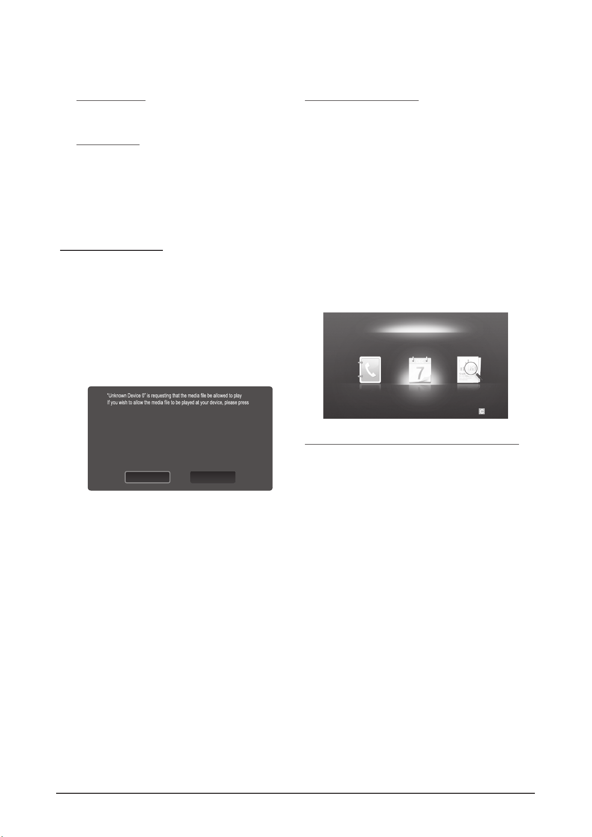
NOTE
If the media function executes for the first time,
the warning popup window appears. Press the
ENTEREbutton to select Allow, then you can use
Media function on that device.
To turn off the media contents transmission from
the mobile phone, set Media to Off in the AllShare
setup.
Contents may not be played on your TV depending
on their resolution and format.
The ENTEREand ◄ / ► buttons may not work
depending on the type of media content.
Using the mobile device, you can control the media
playing. For details, refer to each mobile’s user’s
guide.
When you want to play media contents from
your PC, select the PC icon on the main display
of AllShare. Then the TV’s Media Play menu
automatically changes. For more detail information,
refer to “Media Play”.
Using ScreenShare Function
Screenshare displays the same web page as provide in
mobile. Using ScreenShare, you can open the various
contents saved in a mobile phone. For example, the image
below displays an access page for contents from a mobile.
You can read the mobile’s various files and view the phone
book and calender on the TV. Also, in phone book, you can
make a call to other person, or can send to SMS.
NOTE
In Samsung mobile, ScreenShare must be installed
and the supporting application must be executed;
then you can use the ScreenShare function.
Available buttons on your remote control may vary
for each page.
Doc Viewer can read files in doc format, but cannot
modify them.
The screen display may differ depending on the
connected device.
Using your Samsung phone to control your TV Simply
Before you can use this feature, you must connect to
a Samsung mobile phone that supports ScreenShare
functions. When operating the TV with your mobile phone,
only the POWER,
Y
, P</> and MUTE buttons are
supported.
Even if you keep pressing down on a control button
(channel or volume) on the mobile phone, the value will
only go up or down by one unit.
E
Select Return
My Mobile
Contacts Calendar Doc Viewer
DenyAllow
.
“Allow”, otherwise press “Deny”.
You can also change the setting (or resetting) of this feature at “AllShare
Setup”.
Warning: Please note that if your device is connected to unsecured or
unfamiliar network, unwanted or inappropriate contents might be played.
If you are not sure about the network's identity or content’s appropriateness,
we strongly recommend that you do not “Allow” the request to play.
2-14 Samsung Electronics
Page 24
DLNA (Networking)
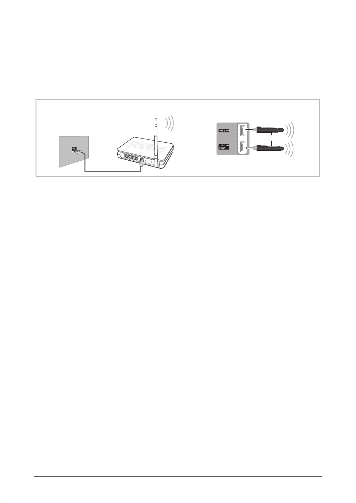
¦ Connecting to a Wireless Network
To connect your TV to your network wirelessly, you need a wireless router or modem and a Samsung Wireless LAN Adapter
(WIS09ABGN), which you connect to your TV’s back or side panel USB jack. See the illustration below.
Samsung’s Wireless LAN adapter is sold separately and is offered by selected retailers, E-commerce sites sites and
Samsungparts.com. Samsung’s Wireless LAN adapter supports the IEEE 802.11A/B/G and N communication protocols.
Samsung recommends using IEEE 802.11N. When you play the video over a IEEE 802.11B/G connection, the video may not
play smoothly.
NOTE
You must use the “Samsung Wireless LAN Adapter” (WIS09ABGN) to use a wireless network.
Samsung’s Wireless L AN adapter is sold separately. The WIS09ABGN Wireless LAN adapter is offered by select
retailers, Ecommerce sites and Samsungparts.com.
To use a wireless network, your TV must be connected to a wireless IP sharer. If the wireless IP sharer supports
DHCP, your T V can use a DHCP or static IP address to connect to the wireless network.
Select a channel for the wireless IP sharer that is not currently being used. If the channel set for the wireless IP sharer
is currently being used by another device nearby, this will result in interference and communication failure.
If you apply a security system other than the systems listed blow, it will not work with the TV.
If Pure High-throughput (Greenfield) 802.11n mode is selected and the Encryption type is set to WEP, TKIP or TKIPAES (WPS2Mixed) for your AP, Samsung TVs will not support a connection in compliance with new Wi-Fi certification
specifications.
If your AP supports WPS (Wi-Fi Protected Setup), you can connect to the network via PBC (Push Button
Configuration) or PIN (Personal Identification Number). WPS will automatically configure the SSID and WPA key in
either mode.
If your router, modem, or device isn’t, certified it may not connect to the T V via the “Samsung Wireless LAN Adapter.”
Connection Methods: You can setup the wireless network connection six ways.
– Samsung Auto Configuration
– PBC (WPS)
– Auto Setup (Using the Auto Network Search function)
– Manual Setup
– SWL (Samsung Wireless Link)
– Ad-Hoc
All of Samsung Wireless LAN Adapter should be connected directly to the TV's USB port. USB HUB are not
supported.
TV Rear Panel
The LAN Port on
the Wall
LAN Cable
Wireless IP sharer
(AP having DHCP server)
Samsung Wireless
LAN Adapter
or
To use the SWL(Samsung Wireless Link) function, connect to the USB 1 (HDD) port.
Product Specification
Samsung Electronics 2-15
Page 25

Product Specification
Network Setup (PBC (WPS))
How to set up using PBC (WPS)
If your router has a PBC (WPS) button, follow these steps:
1. Connect your TV to your LAN as described in the
previous section.
2. Turn on your TV, press the MENU button on your
remote, use the ▲ or ▼ button to select Setup, and
then press the ENTER
E
button.
3. Use the ▲ or ▼ button to select Network in the Setup
menu, and then press the ENTER
E
button.
4. On the Network screen, select Network Type.
5. Set Network Type to Wireless.
6. Select Network Setup. The Network Setup screen
appears.
7. Press the Red button on your remote.
8. Press the PBC (WPS) button on your router within 2
minutes. Your TV player automatically acquires all the
network setting values it needs and connects to your
network.
9. After the network connection is set up, press the
RETURN button to exit the Network Setup screen.
Network Setup (Auto)
Most wireless networks have an optional security system
that requires devices that access the network to transmit
an encrypted security code called an Access or Security
Key. The Security Key is based on a Pass Phrase, typically
a word or a series of letters and numbers of a specified
length you were asked to enter when you set up security for
your wireless network. If you use this method of setting up
the network connection, and have a Security Key for your
wireless network, you will have to enter the Pass Phrase
during the setup process.
How to set up automatically
To set up the wireless connection automatically, follow these
steps:
1. Follow Steps 1 through 6 in the “How to set up using
PBC (WPS)” procedure.
2. Press the ▼ button to select Internet Protocol Setup,
and then press the ENTER
E
button. Press the ▲ or
▼ button to select Auto, and then press the ENTER
E
button.
3. Press the ▲ button to go to Select a Network, and
then press the ENTER
E
button. The Network function
searches for available wireless networks. When done, it
displays a list of the available networks.
4. In the list of networks, press the ▲ or ▼ button to select
a network, and then press the ENTER
E
button.
If the AP is set to Hidden (Invisible), you have
to select Add Network and enter the correct
Network Name (SSID) and Security Key to
establish the connection.
5. If the Security/PIN pop-up appears, go to Step 6. If the
Network Connecting Screen appears, go to Step 10.
6. Press the ▲ or ▼ button to select PIN or Security. For
most home networks, you would select Security (for
Security Key). The Security Screen appears.
7. On the Security screen, enter your network’s Pass
Phrase.
You should be able to find the Pass Phrase on
one of the set up screens you used to set up your
router or modem.
Network Setup
PBC(WPS)
U
Move
E
Enter
R
Return
Select a network : Not Selected ►
Internet Protocol Setup : Auto
IP Address :
Subnet Mask :
Gateway :
DNS Setup : Auto
DNS Server :
A B C D E F G
H I J K L M N
O P Q R S T U
V W X Y Z
0~9
Network Setup
n
Move
E
Enter
R
Return
Security Key
0 entered
Number
Lower case
B
Delete
Space
2-16 Samsung Electronics
Page 26

Product Specification
8. To enter the Pass Phrase, follow these general
directions:
– Press the number buttons on your remote to enter
numbers.
– Use the direction buttons on your remote to move
from button to button on the Security Key screen.
– Press the Red button to change case or display
symbols/characters.
– To a enter letter or symbol, move to the letter or
symbol, and then press the ENTER
E
button.
– To delete the last letter or number you entered, press
the Green button on your remote.
9. When done, press the Blue button on your remote. The
Network Connecting screen appears.
10. Wait until the connection confirmation message is
displayed, and then press the ENTER
E
button. The
Network Setup screen re-appears.
11. To test the connection, press the RETURN button to
select Network Test, and then press the ENTER
E
button.
Network Setup (Ad-Hoc)
You can connect to a mobile device without an access point
through the “Samsung Wireless LAN Adapter” by using a
peer to peer network.
This function is available when SWL(Samsung Wireless
Link) is set to Off.
How to connect to new Ad-hoc device
1. Follow Steps 1 through 6 in the “How to set up using
PBC (WPS)” .
2. Choose Select a network. A list of devices/networks
appears.
3. While in the device list, press the Blue button on the
remote.
The message Ad-hoc is a direct Wi-Fi
connection with cell phone or PC. The existing
network system may have limited functionality.
Do you want to change the network
connection? is displayed.
4. Input the generated Network Name (SSID) and
Security Key into the device you want to connect.
How to connect an existing Ad-hoc device
1. Follow Steps 1 through 6 in the “How to set up using
PBC (WPS)”.
2. Choose Select a network. The Device/Network list
appears.
3. Select the device you want in the Device list.
4. If security key is required, input the security key.
If network doesn’t operate normally, check
the Network Name (SSID) and Security Key
again. An incorrect Security Key may cause a
malfunction.
Network Setup (Manual)
If the other methods do not work, you need to enter the
Network setting values manually.
Getting the Network Connection Values
To get the Network connection values on most Windows
computers, follow these steps:
1. Right click the Network icon on the bottom right of the
screen.
2. In the pop-up menu, click Status.
3. On the dialog that appears, click the Support tab.
4. On the Support tab, click the Details button. The
Network settings are displayed.
How to set up manually
To enter the Network connection values manually, follow
these steps:
1. Follow Steps 1 through 6 in the “How to set up using
PBC (WPS)”.
2. Press the ▼ button to select Internet Protocol Setup,
and then press the ENTER
E
button. Press the ▲
or ▼ button to select Manual, and then press the
ENTERE button.
3. Press the ▼ button to go to the first entry field (IP
Address).
4. Use the number buttons to enter numbers.
5. When done with each field, use the ► button to move
successively to the next field. You can also use the other
arrow buttons to move up, down, and back.
6. Enter the IP Address, Subnet Mask, and Gateway
values.
7. Press the ▲ or ▼ button to go to DNS.
Samsung Electronics 2-17
Page 27

Product Specification
8. Press the ▼ button to go to the first DNS entry field.
Enter the numbers as above.
9. When done, press the ▲ button to go to Select a
Network. Select your network, and then press the
ENTER
E
button.
10. Go to Step 4 in the “How to set up automatically” (p.
31), and follow the directions from that point on.
SWL(Samsung Wireless Link)
This function lets you connect a Samsung device that
supports the PBC (WPS) to your TV. You can connect
devices to the TV even if a sharer is not connected to the TV.
To use the Internet@TV, the AP (access point) must be
connected to the wireless network.
If a Samsung Wireless LAN Adapter is connected to the
USB 2 port, the network may not operate normally. We
recommend to connecting it to the USB 1 (HDD) port.
Only sharers using the 2.4 Ghz band are supported.
Sharers using the 5 Ghz band are not supported.
SWL connect
You can directly connect a device that supports the PBC
(WPS) to the TV.
This function is available when SWL(Samsung
Wireless Link) is set to On.
How to connect Samsung Wireless Link
For the procedures to establish a connection, refer to the
following:
1. Follow Steps 1 through 5 in the “How to set up using
PBC (WPS)”.
2. Select SWL(Samsung Wireless Link) by using the ▼
button and press the ENTER
E
button to turn it On.
3. Select SWL connect by using the ▼ button and press
the ENTER
E
button.
4. If the “Press the PBC button on the device which
supports PBC button to connect within 120
seconds” message appears, press the PBC button on
the device to connect.
For more information, refer to the wireless network
setup manual of the device to be connected.
5. If the device is connected properly to the TV after
starting count on message box then message box will
be disappeared automatically.
If the connection fails, please retry after 2 minutes.
If Your TV Fails to Connect to the Internet
Your TV may not be able to connect to the Internet
because your ISP has permanently registered the
MAC address (a unique identifying number) of your
PC or modem, which it then authenticates each time
you connect to the Internet as a way of preventing
unauthorized access. As your TV has a different MAC
address, your ISP can not authenticate its MAC address,
and your TV can not connect.
To resolve this problem, ask your ISP about the
procedures required to connect devices other than a PC
(such as your TV) to the Internet.
If your Internet service provider requires an ID or password
to connect to the Internet, your TV may not be able to
connect to the Internet. If this is the case, you must enter
your ID or password when connecting to the Internet.
The internet connection may fail because of a firewall
problem. If this is the case, contact your Internet service
provider.
If you cannot connect to the Internet even after you have
followed the procedures of your Internet service provider,
please contact Samsung Electronics at 1-800-SAMSUNG.
2-18 Samsung Electronics
Page 28
Internet@TV
¦ Getting Started with Internet@TV
NOTE
Configure the network settings before using Internet@TV.
Unsupported fonts within the provider’s content will not display normally.
Slow responses and/or interruptions may occur, depending on your network conditions.
English may be only supported in application service depending on region.
This feature is not available in some locations.
If you experience a problem using a application, please contact the content provider.
According to circumstances of the contents provider, an application’s updates or the application itself may be
discontinued.
Depending on your country’s regulations, some application may have limited service or not be supported.
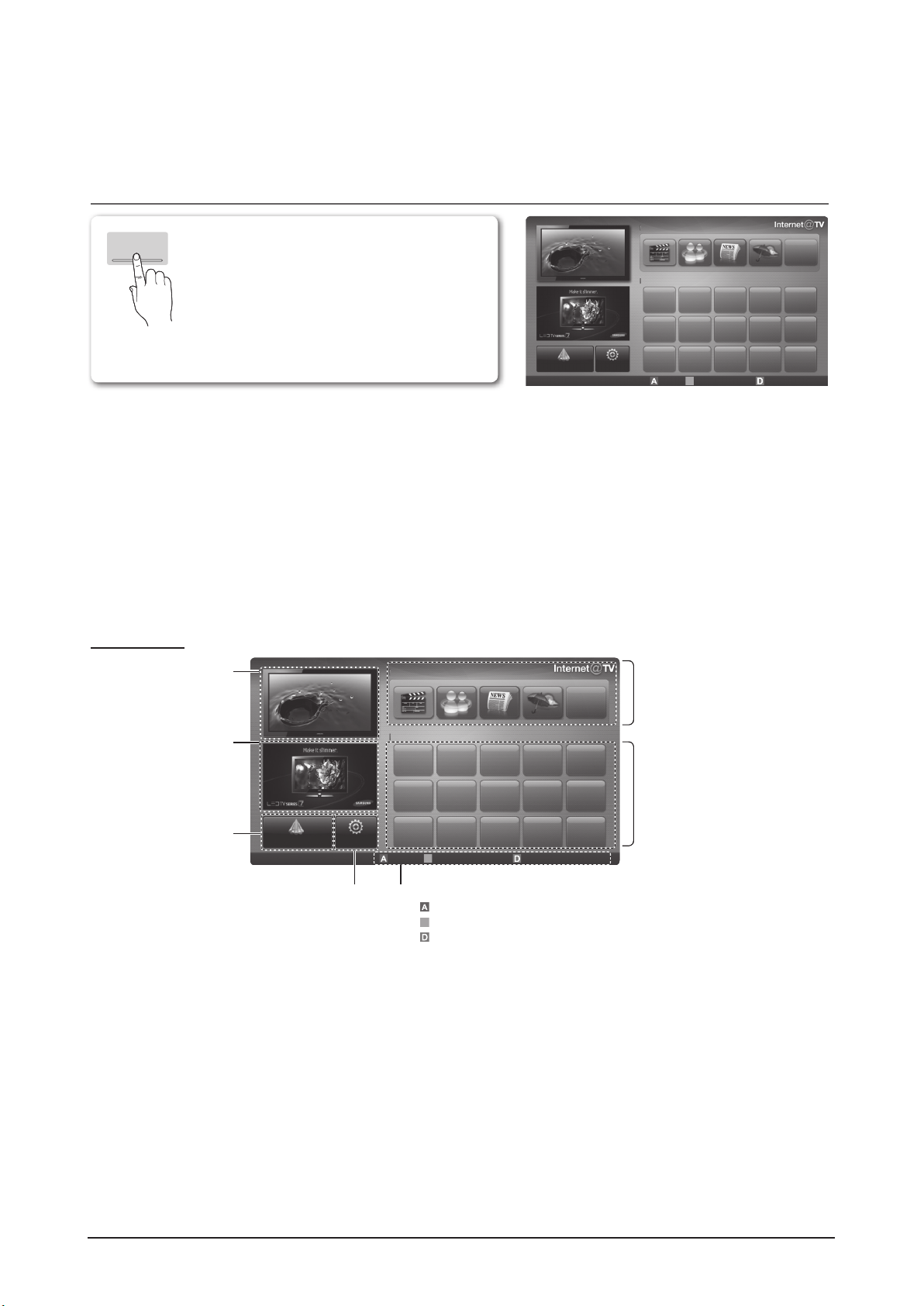
Screen Display
INTERNET
@ TV
Internet@TV brings useful and entertaining
contents and services directly from the web to
your TV.
LoginBMark as Favourite Sort by
R
Return
My Applications
Recommended
by Date 1/1
Settings
Samsung Apps
Recommended Applications:
Displays the recommended service by
Samsung. You are not able to add or
delete a service in this list.
Downloaded Applications:
Displays the downloaded applications
through the Samsung Apps.
TV Screen:
Displays the current channel.
Information:
Displays notices, new
applications, and
advertisements brought to
you by Samsung product
introductions.
Application service:
You can experience
various service by provided
samsung.
Internet@TV Settings:
Edit and configure applications
and Internet@TV settings.
Controls:
• Red (Login): To log in to Internet@TV.
•B Green (Mark as Favourite): To mark the applications as a favourite.
• Blue (Sort by): To sort the applications.
•RReturn: To return to the previous menu.
The colour buttons may work differently depending on the application.
Recommended
Samsung Apps Settings
My Applications
LoginB Mark as Favourite Sort by R Return
by Date 1/1
Product Specification
Samsung Electronics 2-19
Page 29

Product Specification
2-2 Specifications Analysis
Europe Specifications Analysis
Basic
Picture
Audio
Model
Design
Display Type
Built-In Tuner
Resolution 1920 x 1080 1920 x 1080 1920 x 1080
PDP Module
Screen Size
Picture ratio
Brightness 1,500Cd/m2 1,500Cd/m2 1300Cd/m2
Contrast Ratio
Picture Enhacer
Equalizer 5 Band 5 Band 5 Band
Auto Volume
Control
Surround
Sound
PS50C7XXX
PS50C6XXX
PDP TV PDP TV PDP TV
O O O
Samsung SDI US2 Samsung SDI US2 Samsung SDI UF1P
50 inches 63 inches 50 inches
16 : 9 16 : 9 16 : 9
40,000 : 1 40,000 : 1 30,000 : 1
HyperReal Engine HyperReal Engine DNIe
O O O
SRS TheaterSound SRS TheaterSound SRS TruSurround HD
PS63C7XXX PS50C650
Features
Speaker Output
PIP X X O
Double Screen
Caption O O O
Still Image
EPG O O O
My Color
Control
Energy Saving
Screen Burn
Protection
Anynet O O O
10W + 10W 15W + 15W 15W + 15W
X X X
X X X
O O O
O O O
O O O
: Feature Included, X: Not Included
2-20 Samsung Electronics
Page 30

Product Specification
Connections
Model
PS50C7XXX
PS50C6XXX
PS63C7XXX PS50C650
Design
Antenna 1 (Cable/Air) 1 (Cable/Air) 1 (Cable/Air)
AV Input
1 Input 1 Input 1 Input
S-Video X X X
Component
(Y/PB/PR)
PC (D-SUB)
1 Input 1 Input 1 Input
1 Input 1 Input 1 Input
DVI X X X
HDMI 4 Input 4 Input 4 Input
Sub Woofer
O O O
Optical 1 1 1
etc. USB 1 Input USB 1 Input USB 1 Input
ETC Speaker/Stand
Built-in Speaker
3D TV
PVR
Built-in Speaker
3D TV
PVR
: Feature Included, X: Not Included
For the power supply and power consumption, refer to the label attached to the product.
Built-in Speaker
Samsung Electronics 2-21
Page 31

Product Specification
Australia Specifications Analysis
Basic
Picture
Model
PS50C7XXX
PS50C6XXX
PS58C7XXX PS63C7XXX PS50C650
Design
Display Type
Built-In Tuner
PDP TV PDP TV PDP TV PDP TV
O O O O
Resolution 1920 x 1080 1920 x 1080 1920 x 1080 1920 x 1080
PDP Module
Screen Size
Picture ratio
Samsung SDI
US2
50 inches 58 inches 63 inches 50 inches
16 : 9 16 : 9 16 : 9 16 : 9
Samsung SDI
US2
Samsung SDI
US2
Samsung SDI
UF1P
Brightness 1,500Cd/m2 1,500Cd/m2 1,500Cd/m2 1300Cd/m2
Contrast Ratio
Picture Enhacer
40,000 : 1 40,000 : 1 40,000 : 1 30,000 : 1
HyperReal
Engine
HyperReal
Engine
HyperReal
Engine
DNIe
Audio
Features
Equalizer 5 Band 5 Band 5 Band 5 Band
Auto Volume
Control
Surround
Sound
Speaker Output
O O O O
SRS
TheaterSound
SRS
TheaterSound
SRS
TheaterSound
SRS
TruSurround HD
10W + 10W 15W + 15W 15W + 15W 15W + 15W
PIP X X X O
Double Screen
X X X X
Caption O O O O
Still Image
X X X X
EPG O O O O
My Color
Control
Energy Saving
Screen Burn
Protection
O O O O
O O O O
O O O O
Anynet O O O O
: Feature Included, X: Not Included
2-22 Samsung Electronics
Page 32

Product Specification
Connections
Model
PS50C7XXX
PS50C6XXX
PS58C7XXX PS63C7XXX PS50C650
Design
Antenna 1 (Cable/Air) 1 (Cable/Air) 1 (Cable/Air) 1 (Cable/Air)
AV Input
1 Input 1 Input 1 Input 1 Input
S-Video X X X X
Component
(Y/PB/PR)
PC (D-SUB)
1 Input 1 Input 1 Input 1 Input
1 Input 1 Input 1 Input 1 Input
DVI X X X X
HDMI 4 Input 4 Input 4 Input 4 Input
Sub Woofer
O O O O
Optical 1 1 1 1
etc. USB 1 Input USB 1 Input USB 1 Input USB 1 Input
ETC Speaker/Stand
Built-in Speaker
3D TV
PVR
Built-in Speaker
3D TV
PVR
Built-in Speaker
3D TV
PVR
: Feature Included, X: Not Included
For the power supply and power consumption, refer to the label attached to the product.
Built-in Speaker
Samsung Electronics 2-23
Page 33

Product Specification
2-3 Detail Factory Option
If you replace the main board with new one, please change the factory option as well. The options you must
change are “Type”, “Local set” and “Front Color”, “A factory setup data might be different depending on model’s
feature such as inch, and the region they’re going to be sold.”.
Europe Detail Factory Option
Model Name 50" 63"
Vendor SDI SDI
Panel
SMPS
0 Factory Reset - - -
50FArV4/58FArV1/63FArV1/
1 Type
2 Local Set - EU EU
3 Model PC6000/PC7000/PC8000
4 Tuner SEMCO/AUTO SEMCO SEMCO
5 DDR 0/1/2 0 0
6 Light Effect ON/OFF OFF OFF
7 Country
8 Front Color
50FAmV4D/50FArV4D/
58FAmV1D/58FArV1D/
63FAmV1D/63FArV1D
NONE/W-MILKY/T-M-Brn/
T-W-Brn/T-W-Gray/W-D-Gray/
W-M-Whit/W-Violet/T-C-Gray/
CODE BN96-13445A BN96-13446A
SPEC S50FH-YB07 S63FH-YB05
BN44-00333A
(SEMCO)
50FArV4D
(PC7000 / PC6000)
W-VIOLET
(PC7000 / PC6000)
T-R-BLK/S-BLK...
BN44-00334A
(PC7000 / PC6000)
(PC7000 / PC6000)
(SEMCO)
63FArV1D
W-VIOLET
2-24 Samsung Electronics
Page 34

Australia Detail Factory Option
Model Name 50" 58" 63"
Product Specification
Vendor SDI SDI SDI
Panel
CODE BN96-13445A BN96-13336A BN96-13446A
SPEC S50FH-YB07 S58FH-YB04 S63FH-YB05
SMPS
BN44-00333A
(SEMCO)
BN44-00334A
(SEMCO)
BN44-00334A
(SEMCO)
0 Factory Reset - - - -
1 Type
50FArV4/58FArV1/63FArV1/
50FAmV4D/50FArV4D/
58FAmV1D/58FArV1D/
63FAmV1D/63FArV1D
50FArV4D
(PC7000 /
PC6000)
58FArV4D
(PC7000 /
PC6000)
63FArV1D
(PC7000 /
PC6000)
2 Local Set - AD_Au AD_Au AD_Au
3 Model PC6000/PC7000/PC8000
4 Tuner SEMCO/AUTO SEMCO SEMCO SEMCO
5 DDR 0/1/2 0 0 0
6 Light Effect ON/OFF OFF OFF OFF
7 Country
8 Front Color
NONE/W-MILKY/T-M-Brn/
T-W-Brn/T-W-Gray/W-D-Gray/
W-M-Whit/W-Violet/T-C-Gray/
T-R-BLK/S-BLK...
W-VIOLET
(PC7000 /
PC6000)
W-VIOLET
(PC7000 /
PC6000)
W-VIOLET
(PC7000 /
PC6000)
Samsung Electronics 2-25
Page 35

Product Specification
2-4 Accessories
2-4-1 Supplied Accessories
Accessories Item Item code Remark
Owner’s Instructions BN68-02513A
Ferrite Core for
Power Cord
Component Adapter BN39-01154D
AV Adapter BN39-01154C
Scart Adapter BN39-01154B
Remote Control
Batteries
3301-002052
3301-001305
BN59-01049A
BN43-00004A
Samsung Service Center
Cable Tie BN61-05596A
Cleaning Cloth BN63-01798B
Hoder Wire (3EA) BN61-05373A
Hoder Wire Stand BN61-05491A
2-26 Samsung Electronics
Page 36

2-4-2 Sold Separately
Accessories Item Item code Remark
Product Specification
HDMI -
HDMI-DVI -
Component -
Samsung Service Center
Composite (AV) -
Coaxial (RF) -
VGA -
Samsung Electronics 2-27
Page 37

MEMO
2-28 Samsung Electronics
Page 38

3.拆卸和重新组装
3-1 整体拆卸和重新组装
小心
-在拆卸本机前,务必拆开电源线。
-当拆开带有大容量电容器的印刷电路板(如 SMPS、X 主板、Y 主板等等)时,首先给电容器放
电。(电荷可能产生火花,有触电危险。)
-当拆卸和组装本机时,参照电路图检查电缆是否接好,并小心不要损坏电缆。
-小心不要在正面的滤光镜中造成缺陷。
-按与拆卸相反的顺序组装电路板。
-必须将等离子屏置于铺有垫子的平坦表面上,以便拆卸和重新组装。
说明 说明相片
拆卸和重新组装
1.拆除 1 个螺钉。
:BH,+,S,M4,L10,ZPC(BLK),SWRCH18
*L :螺钉长度(mm)
2.推动两侧并下拉接线,将之从机体上卸下。
:当拆除底座时,请将等离子电视面向下
置于柔软表面上。
3.拆除 5 个螺钉。
BH、+、B、M4、L12、ZPC(BLK)、SWRCH18
:
*L :螺钉长度(mm)
4.拆除基座。
三星电子 3-1
Page 39

拆卸和重新组装
说明 说明相片
5. 拆除21个螺钉。 ( ) (50" PDP)
拆除22个螺钉。( ) (58"/63" PDP)
:BH,+,B,M4,L12,ZPC(BLK),SWRCH18
*L :螺钉长度(mm)
6. 拆除6个螺钉。 ( )
:BH,+,S,M4,L10,ZPC(BLK),SWRCH18
*L :螺钉长度(mm)
7. 拆卸后盖。
8. 拆除4个螺钉。( ) (50" PDP)
拆除6个螺钉。( ) (58"/63" PDP)
:BH,+,S,M4,L10,ZPC(BLK),SWRCH18
*L :螺钉长度(mm)
9. 拆除2个螺钉。( )
:BH,+,B,M4,L12,ZPC(BLK),SWRCH18
*L :螺钉长度(mm)
10. 拆卸支持架座。
3-2 三星电子
Page 40

说明 说明相片
11. 拆卸主板上的所有连接器。
12. 拆卸6个螺钉。
:PH,+,WSP,M3,L10,NI PLT,SWRCH18A
*L :螺钉长度(mm)
13. 拆卸主板。
拆卸和重新组装
14. 拆除4个螺钉。
:BH,+,WP,S,M4,L10,ZPC(BLK)
*L :螺钉长度(mm)
15. 拆除低音扩音器。
16. 从SMPS处拆卸所有连接器。
17. 拆除2个螺钉。 ( )
:PH,+,WSP,M3,L10,NI PLT,SWRCH18A
*L :螺钉长度(mm)
18. 拆除1个螺钉。 ( )
:BH,+,S,M4,L8,ZPC(WHT),SWRCH18A
*L :螺钉长度(mm)
19. 拆除FILTER-EMI的交流线。
三星电子 3-3
Page 41

拆卸和重新组装
说明 说明相片
20. 拆卸SMPS处的所有螺钉。
21. 拆卸6个螺钉。(50" PDP)
拆除8个螺钉。(58"/63" PDP)
:PH,+,WSP,M3,L10,NI PLT,SWRCH18A
*L :螺钉长度(mm)
22. 拆除SMPS。
在处理电源板时要戴上手套,因为在电容
器中可能还有残留电荷。尤其,不要去触
摸电容器的任何部分。
23. 拆除逻辑主板上的所有连接器。
24. 拆除2个螺钉。
:PH,+,WSP,M3,L10,NI PLT,SWRCH18A
*L :螺钉长度(mm)
25. 拆除逻辑主板。
3-4 三星电子
Page 42

说明 说明相片
26. 拆除X主板上的所有连接器。
※如要将X主板上的扁平线分离,按下连接器
的上侧和下侧。
拆卸和重新组装
27. 拆除7个螺钉。 (50" PDP)
拆除11个螺钉。(58" PDP)
拆除13个螺钉。 (63" PDP)
:PH,+,WSP,M3,L10,NI PLT,SWRCH18A
*L :螺钉长度(mm)
28. 拆除X主板和X缓冲板。
三星电子 3-5
Page 43

拆卸和重新组装
说明 说明相片
3-6 三星电子
Page 44

说明 说明相片
29. 从顶部和底部的两端拉动手柄,将扫描板
从屏板处卸下。
拆卸和重新组装
三星电子 3-7
Page 45

拆卸和重新组装
说明 说明相片
30. 拆卸Y主板上的所有连接器。
31. 拆卸11个螺钉。(50" PDP)
拆卸16个螺钉。 (58"/63" PDP)
:PH,+,WSP,M3,L10,NI
PLT,SWRCH18A
*L :螺钉长度(mm)
32. 拆卸带有Y缓冲板的Y主板。
3-8 三星电子
Page 46

说明 说明相片
33. 拆卸4个螺钉。
:BH,+,S,M4,L10,ZPC(BLK),SWRCH18
*L :螺钉长度(mm)
34. 拆卸墙架。
拆卸和重新组装
35. 拆除5个螺钉。 (50" PDP)
拆除9个螺钉。 (58"/63" PDP)
:BH,+,B,M4,L12,ZPC(BLK),SWRCH18
*L :螺钉长度(mm)
36.拆卸P-过滤器架底部。
当拆卸前盖时,请将等离子电视面向下
置于柔软表面上。
三星电子 3-9
Page 47

拆卸和重新组装
说明 说明相片
37. 拆除1个螺钉。
:BH,+,B,M4,L12,ZPC(BLK),SWRCH18
*L :螺钉长度(mm)
38. 拆卸触摸功能板和IR板上的所有连接器。
39. 拆卸触摸功能板和IR板。
40. 拆除1个螺钉。
:BH,+,B,M4,L12,ZPC(BLK),SWRCH18
*L :螺钉长度(mm)
41. 拆除3D发射器板上的所有连接器。
42. 拆除3D发射器板。
3-10 三星电子
Page 48

4.故障排除
4-1 故障排除
4-1-1 故障排除第一检查表
1. 首先检查各种电缆连接。
-检查电缆是否烧坏或损坏。
-检查电缆是否断开或连接处太松。
-依据连接图检查是否连接电缆。
2. 检查主板的电源输入。
3. 检查如下电压:
-SMPS 到主板。
-SMPS 到 X 主板。
-SMPS 到 Y 主板。
-SMPS 到逻辑板。
故障排除
三星电子 4-1
Page 49

故障排除
4-1-2 按错误模式分类的检查点
未通电
-当连接电源线时,前面板上的 LED 指示灯不工作。
征兆
主要检查表
-当连接电源线时,SMPS 继电器不工作。
-设备的电源似乎有故障。
如果电缆连接不当或主板或 SMPS 有故障,当连接电源线时,前面板上的 SMPS 继
电器或 LED 指示灯不工作。
在这种情况下,检查下列各项:
-检查本机内的内部电缆连接状态。
-检查保险丝。
-检查 SMPS 的输出电压。
-更换主板。
开始
交流电源线是否连接?
交流电插孔(CN800S)
保险丝F801S、
FS802S 是否断开?
是
是否被连接?
是
是
否
否
否
插入电源线并重新测试
插入连接器并重新测试
更换保险丝并重新测试
故障是否解决?
否
故障是否解决?
否
故障是否解决?
否
是
是
是
A
B
4-2 三星电子
Page 50

故障排除
A
B
在 CN801 管脚 16 上
是否有 5V 待机电压?
是
否
更换 SMPS 并重新测试
故障是否解决?
否
是
更换主印刷电路板并重新
测试
结束
三星电子 4-3
Page 51

故障排除
当本机重复开机和关机时
征兆 -SMPS 继电器重复开机和关机。
通常,因与 SMPS 相接的电路板上的缺陷,保护功能会重复打开和关闭 SMPS 继电器。
-从 SMPS 断开所有电缆,只运行 SMPS,并检查 SMPS 工作是否正常,以及各电压
主要检查表
输出是否正确无误。
-如果即使当 SMPS 单独运行时仍有征兆,则更换 SMPS。
-如果当单独运行 SMPS 时未观察到征兆,依次连接电缆来找到有缺陷的组件。
小心
当拆开和连接SMPS和X主板和Y主板电缆时,大容量电容器的电荷可能产生火花。因
此,在从本机拆开电源线后等待一些时间。
检查供应电源上的Va和
电压是否与屏板滞留
器的电压匹配?
更换主印刷电路板并再次
开始
Vs电压
是
测试
否
调节电压与滞留器匹配并
再次测试
故障是否解决?
否
是
故障是否解决?
否
C
是
D
4-4 三星电子
Page 52

关机,等待一段时间,从
SMPS上拔下X和Y主板,
然后开机。
故障排除
C
D
SMPS 仍旧开启吗?
是
关机,等待一段时间,连
接Y主印刷电路板在尝试
开机。
是否保持开机状态?
更换 X 主板并再次测试
否
更换 SMPS 并再次测试
否
更换 Y 主板并再次测试
故障是否解决?
否
电视是否正常运行?
否 是
是
是
E
F
三星电子 4-5
Page 53

故障排除
E
F
故障是否解决?
是
更换逻辑板
故障是否解决?
否
是
否
更换屏板
结束
4-6 三星电子
Page 54

无声音
主要检查表
故障排除
征兆 -图像正常但没有声音。
-当扬声器连接器断开或损坏时。
-当主板的声音处理器有故障时。
-扬声器缺陷。
开始
主印刷电路板上的连接
是否正常?(CN2001)
是
在 CN801 的管脚 1、3
和 5 上的电压是否为
12V?
是
重新连接并再次测试
否
更换 SMPS 并重新测试
否
故障是否解决?
是
否
故障是否解决?
是
否
主板上的扬声器的输
出终端是否正常?
是
更换扬声器
结束
否
更换主印刷电路板
故障是否解决?
是
否
三星电子 4-7
Page 55

故障排除
当 3D 玻璃出现故障时
使用你手机上的照相机功能在 3D 发射器前
部照明
如果 3D 发射器不能闪烁
TV 发生故障
(3D 发射器或主板损坏)
3D 发射器的位置
在 3D 发射器前部开启 3D 玻璃灯
如果仅 3D 发射器前部右端的 3D 玻
璃可以运作
如果 3D 玻璃不能正常的运作
如果不考虑距离问题,3D 玻璃
可以正常运作
3D 发射器损坏
3D 玻璃损坏
3D 发射器和 3D 玻璃都没问题
4-8 三星电子
Page 56

4-1-3 故障及纠正措施
征兆 相关图像 原因和解决办法
故障排除
地址缓冲器缺陷
屏幕上出现竖直空白单元格
(块)。
打开电视时出现绿屏。
出现 OSD 框,但无文字。
-更换相应上/下缓冲器(E、F 或 G)
COF 缺陷(烧断)
-更换模块
未重设定标
-更换主板
程序版本错误
-检查各个程序版本
屏幕上出现上(或下)空白块。
-更换主板
上/下 Y 缓冲器缺陷
-更换相应上/下缓冲器
三星电子 4-9
Page 57

故障排除
征兆 相关图像 原因和解决办法
未显示主或副图片。
屏幕上出现竖直绿线。
暗淡屏幕(红色模糊屏幕)
更换主板
SMPS 电压错误
-根据模块标签上印刷的电压调节
SMPS 电压
X-主板缺陷
-更换 X-主板
4-10 三星电子
Page 58

4-1-4 按组件分类的故障排除步骤
■ 50"等离子
组件 主要征兆
SMPS-PDP TV
ASSY PDP P-X-MAIN BOARD
ASSY PDP P-Y-MAIN BOARD
ASSY PDP P-LOGIC MAIN BOARD
ASSY PDP P-X-MAIN BUFFER BOARD
ASSY PDP P-Y-MAIN BUFFER BOARD
ASSY PDP P-E-BUFFER BOARD
ASSY PDP P-F-BUFFER BOARD
ASSY PCB MISC-MAIN
ASSY BOARD P-TOUCH FUNCTION&IR
ASSY BOARD P-3D EMITTER
故障排除
※如果发生主要症状,按照下表所示检查组件。
没有通电,空白屏幕,继电器重复开和关。
空白屏幕
空白屏幕
空白屏幕,屏幕噪声
上部屏幕空白
下部屏幕空白
相应的缓冲器板块屏幕空白
相应的缓冲器板块屏幕空白
未通电,各输入源屏幕异常、画中画屏幕故障、声音故障
功能键工作不正常
遥控器工作不正常,LED 工作不正常。
3D 模式不能正常运行。
三星电子 4-11
Page 59

故障排除
■ 58"/63"等离子
组件 主要征兆
SMPS-PDP TV
ASSY PDP P-X-MAIN BOARD
ASSY PDP P-Y-MAIN BOARD
ASSY PDP P-LOGIC MAIN BOARD
ASSY PDP P-Y SCAN UPPER BOARD
ASSY PDP P-Y SCAN LOWER BOARD
ASSY PDP P-X-MAIN BUFFER BOARD
ASSY PDP P-E-BUFFER BOARD
ASSY PDP P-F-BUFFER BOARD
ASSY PDP P-G-BUFFER BOARD
ASSY PCB MISC-MAIN
ASSY BOARD P-TOUCH FUNCTION&IR
ASSY BOARD P-3D EMITTER
没有通电,空白屏幕,继电器重复开和关。
空白屏幕
空白屏幕
空白屏幕,屏幕噪声
空白屏幕
空白屏幕
空白屏幕
相应的缓冲器板块屏幕空白
相应的缓冲器板块屏幕空白
相应的缓冲器板块屏幕空白
未通电,各输入源屏幕异常、画中画屏幕故障、声音故障
功能键工作不正常
遥控器工作不正常,LED 工作不正常。
3D 模式不能正常运行。
4-12 三星电子
Page 60

4-2 调节
4-2-1 维修说明
在进行售后服务之前
1. 检查测量和测试设备运行是否正常。
2. 确保有足够工作空间,用于拆卸产品。
3. 准备软垫,用于拆卸产品。
更换电路板后的维修调节项目
<如有调节设备可用>
1. 工厂模式 PDP 选项→将工厂数据类型项目设为相关机型的适当值。
2. 调节各个模式的工厂模式的校准
故障排除
3. 调节工厂模式的白平衡
<如无调节设备可用>
1. 写下工厂模式 HDMI 白平衡的值,然后更换电路板。
2. 工厂模式的 PDP 选项→将工厂数据类型项目设为相关机型的适当值。
3. 用之前记录的值设置 HDMI 白平衡的值。
三星电子 4-13
Page 61

故障排除
4-2-2 如何进入维修模式
1. 通用遥控
如欲进入:POWER OFF INFO MENU MUTE POWER ON
如欲退出:POWER OFF POWER ON
2. 工厂遥控
如欲进入:POWER ON INFO Factory Key(击键间隔:不到3秒)
如欲退出:按下工厂键两次(按下一次进入老化模式)
3. 当进入工厂模式时设置
-清晰屏幕(动态)、色调(冷色 1)、工厂(动态 CE 关)
4. 调节步骤
-频道▲▼键:选择项目
-音量◄►键:调大或调小值。
-菜单键:将修改内容存入 EEPROM,并返回上一级模式。
-使用数字(0~9)键,可以选择频道。
-使用来源键,可以切换 AV 模式。
5. 初始维修模式显示状态
如果想要进入到此菜单,应当按下
按钮0 → 0 → 0 → 0。
此菜单没有被激活。
屏幕最下一行上显示的固件版本可能有所不同,固件可能有变动,以便改进产品功能。
如果在维修模式下调节了设置,必须将产品复位。
4-14 三星电子
Page 62

4-2-3 工厂数据
■ 选项
故障排除
三星电子 4-15
Page 63

故障排除
■ 控制
4-16 三星电子
Page 64

故障排除
三星电子 4-17
Page 65

故障排除
■ 专家:此菜单没有被激活。
4-18 三星电子
Page 66

■ ADC/WB
故障排除
三星电子 4-19
Page 67

故障排除
4-20 三星电子
Page 68

■ 高级
故障排除
三星电子 4-21
Page 69

故障排除
4-22 三星电子
Page 70

4-2-4 维修调节
白平衡-校准
如果画面颜色有误,首先要校准。
在工厂模式下进行校准
1. 来源:视频
2. 设置模式:PA L (模式:#2)
3. 图案:图案#24(方格图)
4. 所用设备:K-7256 或同等设备
5. 工作顺序
1)通过工厂模式选择“ADC/WB”来进入。
2)选择“ADC”。
3)在校准菜单中再次选择“AV CALIBR AT I ON”。
故障排除
4)在完成校准后,在屏幕上显示“AV succes s ” OSD。
来源 AV:PAL 复合
PC:1280*720/60Hz
(方格图)
三星电子 4-23
Page 71

故障排除
白平衡
规格调节
1.来源:HDMI
2.设置模式:
1280*720@60Hz
3.图案:图案 #92
4.所用设备:MIK-7256 (MSPG925L)
5.工作顺序
1)连接 MIK-7256(MSPG925L)的 HDMI(DVI)输出端子到 HDMI 输入主机上。
2)设置输入到 MDMI 模式。
3)进入白平衡的菜单服务模式。
4)连接 CA-210 传感器到滤光器。
<固定 CA210 的探针位置>
4-24 三星电子
Page 72

5)调节弱光
-调节副亮度,设置为“Y”值。
-调节红色偏移(“X”)和蓝色偏移(“Y”)到颜色座标。
*不要调节 G-偏移数据
6)调节高光
-调节副对比度,设置为“Y”值。
-调节红色增益(“X”)和蓝色增益(“Y”)到颜色座标。
*不要调节 G-增益数据
■ 50" 等离子
输入模式
x y Y(L) T(K), MPCD
CVBS
H/L 278 285
(PAL)
L/L 278 285 7.3 cd/m² (2.2 Ft) 10,500/±0
COMP
H/L 278 285
(720P)
L/L 278 285 7.3 cd/m² (2.2 Ft) 10,500/±0
HDMI
H/L 278 285
(720P)
L/L 278 285 7.3 cd/m² (2.2 Ft) 10,500/±0
■ 58"/63"等离子
输入模式
x y Y(L) T(K), MPCD
CVBS
H/L 278 285
(PAL)
L/L 278 285 6.9 cd/m² (2.2 Ft) 10,500/±0
COMP
H/L 278 285
(720P)
L/L 278 285 6.9 cd/m² (2.2 Ft) 10,500/±0
HDMI
H/L 278 285
(720P)
L/L 278 285 6.9 cd/m² (2.2 Ft) 10,500/±0
(CA-210)
不控制
(Sub_CT:133)
不控制
(Sub_CT:133)
不控制
(Sub_CT:133)
(CA-210)
不控制
(Sub_CT:133)
不控制
(Sub_CT:133)
不控制
(Sub_CT:133)
故障排除
10,500/±0
10,500/±0
10,500/±0
10,500/±0
10,500/±0
10,500/±0
三星电子 4-25
Page 73

故障排除
4-2-5 更换和校准
*在更换各组件之后检查项目列表
■ 50" 等离子
更换组件项目 检查项目
ASSY PCB MISC-MAIN
SMPS-PDP TV
ASSY PDP P-X-MAIN BOARD
ASSY PDP P-Y-MAIN BOARD
ASSY PDP P-LOGIC MAIN BOARD
ASSY PDP P-X-MAIN BUFFER BOARD
ASSY PDP P-Y-MAIN BUFFER BOARD
ASSY PDP P-E-BUFFER BOARD
ASSY PDP P-F-BUFFER BOARD
ASSY BOARD P-TOUCH FUNCTION&IR
ASSY BOARD P-3D EMITTER
1自动程序
2白色平衡调节
检查并调节 Vs、Va 电压
不调节
当更换 SMPS 或 PDP 显示屏时,必须检查显示屏标签上印刷的电压,并调节该电压。
4-26 三星电子
Page 74

■ 58"/63"等离子
更换组件项目 检查项目
ASSY PCB MISC-MAIN
SMPS-PDP TV
ASSY PDP P-X-MAIN BOARD
ASSY PDP P-Y-MAIN BOARD
ASSY PDP P-LOGIC MAIN BOARD
ASSY PDP P-Y SCAN UPPER BOARD
ASSY PDP P-Y SCAN LOWER BOARD
ASSY PDP P-X-MAIN BUFFER BOARD
ASSY PDP P-E-BUFFER BOARD
ASSY PDP P-F-BUFFER BOARD
ASSY PDP P-G-BUFFER BOARD
ASSY BOARD P-TOUCH FUNCTION&IR
ASSY BOARD P-3D EMITTER
故障排除
1自动程序
2白色平衡调节
检查并调节 Vs、Va 电压
不调节
当更换 SMPS 或 PDP 显示屏时,必须检查显示屏标签上印刷的电压,并调节该电压。
三星电子 4-27
Page 75

故障排除
■ 调节电压
1. 在更换 SMPS 或 PDP 显示屏后,必须参照显示屏上印刷的电压标签调节该电压。
(如果未调节该电压,可能出现异常放电征兆。)
值
调节板
US2
Vs
Va
Vset
Ve
Vsc
207
56
-
97
-197
SMPS
2. 主 SMPS 电压调节点。
电压标签
VS 调节
VS 测试点
VA 测试点
VA 调节
4-28 三星电子
Page 76

■ SMPS 输出电压
故障排除
三星电子 4-29
Page 77

故障排除
■Y-RR 和 Y-FR 控制
※通过改变可变电阻值设置主复位(升:60usec, 降:80usec)
■ 波形调节(Y 主板输出波形)(Y 板第一 子域波形)
Yfr(下降斜坡)可变电阻器
如要降低扁平不放呢,顺时针转动末端
Yfr可变电阻器
Yrr(上升斜坡)可变电阻器
如要降低扁平不放呢,顺时针转动末端
Yrr可变电阻器
4-30 三星电子
Page 78

■ TP 点
故障排除
TP 点 TP点
1. 波形斜率调节
2. 上坡斜率
1) 延伸预设上升部分的第一子域。
2) 调节数值范围到 50V,10us 级。
3) 调节波形如下 C(上升边缘)、D。
Yff 间隔
Yfr 间隔
(Y 板第一 子域波形)
三星电子 4-31
Page 79

故障排除
3. 下坡斜率
1) 延伸主预设下坡部分的第一子域。
2) 调节数值范围到 50V,10us 级。
3) 调节波形如下 C(下坡边缘)、D。
4-32 三星电子
Page 80

4-3 升级
4-3-1 如何检测程序版本
1.在工厂菜单下检查程序。
当进入工厂模式时,软件版本将会显示在 4-2-2 页“如何进入到维修模式”的菜单底端。
主程序版本
Micom 版本
4-3-2 如何升级软件(USB)
1.复制升级文件到USB闪存驱动的“T-VALDEUC”路径中。
2.USB下载
1)在待机模式中,将USB存储棒插入到USB端口中。
2)开机。
3)在菜单“支持”中按下“菜单”并查找“软件升级”。
4)在菜单中选择“软件升级”。
5)在菜单中选择“通过USB”。
故障排除
三星电子 4-33
Page 81

故障排除
6)标语OSD中将会显示“正在扫描USB…”。
7)标语 OSD中将会显示“有效版本…升级版本…”,并选择
“确认”。
8)标语 OSD中显示“正在升级…”,大约需要1分钟的时间。
(警告:在升级过程中不要将USB闪存驱动取下。)
9)当升级完成时,标语OSD中将会显示“升级完成”。
10)将USB闪存驱动从PDP TV上取下,并检查程序版本。
4-34 三星电子
Page 82

4-3-3 如何升级软件
1.网络下载
1)将局域网接线插入到局域网端口中。
2)开启电源。
3)按下“菜单“并在菜单“支持”中查找“软件升级”。
4)在菜单中选择“软件升级“。
5)在菜单中选择“通过在线”。
6)标语OSD中将会显示“连接到网络服务器”。
7)标语OSD中将会显示“有效版本…升级版本…”,并选
择“确认”。
8)标 语 OSD中显示“正在升级…”,大约需要1分钟的时间。
故障排除
三星电子 4-35
Page 83

故障排除
9)当升级完成时,标语OSD中将会显示“升级完成”。
10)检查程序版本。
4-36 三星电子
Page 84

备忘录
故障排除
三星电子 4-37
Page 85

Exploded View & Part List
F001A
F001
FB21A
AC280
SP01A
SB04A
SP01A
M0014
U001A
R001A
HC001
5. Exploded View & Part List
5-1 Exploded View
5-1 Samsung Electronics
This Document can not be used without Samsung’s authorization.
Page 86

Exploded View & Part List
Part List
Loc. No. Part No. Description;Specification Qty. SNA Remark
AC280 BN63-06767A COVER-PCB;UC8K,HIPS,V0, BLK 1 SNA
F001 BN63-06524E COVER-FRONT;63PC7000,PMMA(Clear)+PMMA-AB 1 SNA
F001A BN96-12997P ASSY COVER P-FRONT;PC7000 63,PMMA(Clear) 1 SA
FB21A BN96-14504B ASSY BOARD P-TOUCH FUNCTION&IR;63PC7000, 1 SA
HC001 BN61-04922A HOLDER-CORD;LB7000 46,ABS,V0,BLK 1 SA
M0014 BN94-03488A ASSY PCB MISC-MAIN;PS58C7000YFXXZ,F76A 1 SA
R001A BN96-13010J ASSY COVER P-REAR;PC7000 63,XZ(DTV),PCM, 1 SA
SB04A BN96-13026A ASSY STAND P-BASE;PC7000 58,SUS T0.6 1 SA
SP01A BN96-12942C ASSY SPEAKER P;8ohm,4pin,15,L:280 R:900, 1 SA
SP01A BN96-13273C ASSY SPEAKER P;4ohm,4pin,25W,R:960,Enclo 1 SA
U001A BN96-13447A ASSY PDP MODULE P;S63FH-YB05,PL63FF012B, 1 SA
Samsung Electronics 5-2
This Document can not be used without Samsung’s authorization.
Page 87

Exploded View & Part List
5-2 Service Item
Loc. No. Part No. Description;Specification Qty. Remark
SP01A BN96-12942C ASSY SPEAKER P;8ohm,4pin,15,L:280 R:900, 1
F001A BN96-12997P ASSY COVER P-FRONT;PC7000 63,PMMA(Clear) 1
FB21A BN96-14504B ASSY BOARD P-TOUCH FUNCTION&IR;63PC7000, 1
R001A BN96-13010J ASSY COVER P-REAR;PC7000 63,XZ(DTV),PCM, 1
SB04A BN96-13026A ASSY STAND P-BASE;PC7000 58,SUS T0.6 1
SG03 BN61-06119A GUIDE-STAND;58PC6500,PC,G/F 20%,V2,BK000 1
HC001 BN61-04922A HOLDER-CORD;LB7000 46,ABS,V0,BLK 1
M2893 BN39-01267E LEAD CONNECTOR;LB6T,FLAT CONNECTOR ASS’Y 1
P001A BN44-00334A DC VSS-PDP TV;PZ-8A,AC/DC,AC100~240V,50/ 1
FL06 BN96-12723T ASSY CABLE P-FPCB LVDS;PDP 63 U/SLIM,FPC 1
SP01A BN96-13273C ASSY SPEAKER P;4ohm,4pin,25W,R:960,Enclo 1
U001A BN96-13447A ASSY PDP MODULE P;S63FH-YB05,PL63FF012B, 1
UX03A BN96-12689A ASSY PDP P-X MAIN BOARD;S63-FH-YB05,PL63 1
UX02A BN96-12690A ASSY PDP P-X BUFFER UPPER BOARD;S63-FH-Y 1
UX01A BN96-12691A ASSY PDP P-X BUFFER LOWER BOARD;S63-FH-Y 1
UY04A BN96-12692A ASSY PDP P-Y MAIN BOARD;S63-FH-YB05,PL63 1
UY03A BN96-12693A ASSY PDP P-Y BUFFER UPPER BOARD;S63-FH-Y 1
UY02A BN96-12694A ASSY PDP P-Y BUFFER LOWER BOARD;S63-FH-Y 1
UL01A BN96-12695A ASSY PDP P-LOGIC MAIN BOARD;S63-FH-YB05, 1
UE01A BN96-12696A ASSY PDP P-E-BUFFER BOARD;S63-FH-YB05,PL 1
UF01A BN96-12697A ASSY PDP P-F-BUFFER BOARD;S63-FH-YB05,PL 1
UG02A BN96-12698A ASSY PDP P-G-BUFFER BOARD;S63-FH-YB05,PL 1
M0014 BN94-03488A ASSY PCB MISC-MAIN;PS58C7000YFXXZ,F76A 1
IC125 BN13-00031A IC ASIC;LUNA,SDP95,400,3.6,-40to+125C,CA 1
ET01 BN40-00184A TUNER;DNCS443VH161A(S),DTMB/PAL/NTSC,75o 1
T0066 BN96-09872H ASSY POWER CORD;BK,LSG-31 10A/250V,Y,P48 1
M0114 BN39-01154B CBF SIGNAL;Chelsea Slim,24P/RCA3P,30AWG, 1
M0114 BN39-01154C CBF SIGNAL;Chelsea Slim, STEREO Plug to 1
M0114 BN39-01154D CBF SIGNAL;Chelsea Slim, STEREO Plug to 1
REMO2 BN59-01049A REMOCON;TM1080,SAMSUNG,20PIN SINGLE,49KE 1
EH02A BN96-10810A ASSY HOLDER P;09 LEDTV MODEL,NYRON 1
RB01 BN63-06485A COVER-BOTTOM;58PC750,HIPS,V0,V1,BLK(BK-5 1
M0254 AA59-00416B ANT SHIELD BOX;UGC-AS-003A,PAL-BG,DK,I,M 1
5-3 Samsung Electronics
This Document can not be used without Samsung’s authorization.
Page 88

6. Wiring Diagram
AC
INLET
Y MAIN
SMPS
X-MAIN
MAIN
LOGIC
E-BUFFER
IR
WOOFER
SPEAKER
CN2005
F-BUFFER
CN1001
CN2001
CN9301
CN2001
CN4001
1
2
6
7
8
3
45
6-1 Overall Wiring
50" Overall Wiring (Europe/Australia)
Wiring Diagram
Samsung Electronics 6-1
Page 89

Wiring Diagram
CN5400
CN5412
CN5413
CN5505
CN5506
CN5507
CN5004
CN5002
CN5003
CN804 CN803
CN800S CN802
CN801
CN2000
CN2006
CN2003
CN2004
CN2013
CN2007
CN2508
CN2501
CN2701
CN4001
CN4408
CN4407
CN4406
CN4405
AC
INLET
Y MAIN
SMPS
X-MAIN
MAIN
LOGIC
E-BUFFER G-BUFFER
CN4002
IR
WOOFER
SPEAKER
CN4409
CN4410
CN2005
CN2601
F-BUFFER
CN1001
CN2001
CN9301
CN2001
CN4001
1
2
6
7
8
3
45
58" Overall Wiring (Australia)
6-2 Samsung Electronics
Page 90

63" Overall Wiring (Europe/Australia)
CN5400
CN5412
CN5413
CN5505
CN5506
CN5507
CN5004
CN5002
CN5003
CN804 CN803
CN800S CN802
CN801
CN2000
CN2006
CN2003
CN2004
CN2013
CN2007
CN2508
CN2501
CN2701
CN4001
CN4603
CN4605
CN4606
CN4604
AC
INLET
Y MAIN
SMPS
X-MAIN
MAIN
LOGIC
E-BUFFER G-BUFFER
CN4002
IR
WOOFER
SPEAKER
CN4502
CN4510
CN2005
CN2601
F-BUFFER
CN1001
CN2001
CN9301
CN2001
CN4001
1
2
6
7
8
3
4
5
Wiring Diagram
Samsung Electronics 6-3
Page 91

Wiring Diagram
The code number of cable(Lead-connector) can be changed, see “5. Exploded View & Part List.”
50"/58"/63" Cable (Lead-connector)
Use
Code
Photo
2 POWER 18P
50" - BN39-01267H
58" - BN39-01267A
63" - BN39-01267E
6 LVDS FFC 82P 1 FILTER-EMI AC LINE
50" - BN96-12723U
58" - BN96-12723S
63" - BN96-12723T
50" - 2901-001615
58"/63" - 2901-001617
6-4 Samsung Electronics
Page 92

6-1-1 Pin Connection
Wiring Diagram
CN800S (SMPS)
↔ AC Inlet socket
Pin No.
1 L
2 N
1
Signal
2
CN801 (SMPS) ↔ CN1001 (Main Board)
Pin No.
1 PS_ON 10 18V
2 STD5V 11 18V
3 5.3V 12 5.3V
4 GND 13 5.3V
5 GND 14 GND
6 GND 15 GND
7 GND 16 15V
8 N/C 17 15V
9 N/C 18 15V
Signal Pin No. Signal
3
CN802 (SMPS)
↔ CN2000 (Logic Board)
Pin No.
1 D5.3V
2 D5.3V
3 GND
4 GND
5 PS_ON
6 VS_ON
Signal
4
CN803 (SMPS)
↔ CN4006 (X Board)
Pin No.
1 Vg
2 GND
3 GND
4 Vs
5 Vs
Signal
5
CN804 (SMPS)
↔ CN5005 (Y Board)
Pin No.
1 Vs
2 Vs
3 GND
4 Vg
5 GND
6 Va
Signal
Samsung Electronics 6-5
Page 93

Wiring Diagram
6
CN9301 (MAIN Board) ↔ CN2013 (Logic Board)
Pin No.
Signal Pin No. Signal Pin No. Signal
1 GND 29 Ch1[4]+
2 UART Tx 30 Ch1[4]-
3 GND 31 Ch1[3]+
4 UART Rx 32 Ch1[3]-
5 GND 33 GND
6 N/C 34 Ch1CLK+
7 GND 35 Ch1CLK-
8 SDA 36 GND
9 GND 37 Ch1[2]+
10 N/C 38 Ch1[2]-
11 GND 39 Ch1[1]+
12 SCL 40 Ch1[1]-
13 GND 41 Ch1[0]+
57 Ch2[2]-
58
Ch2[2]+
59 GND
60
Ch2CLK-
61 Ch2CLK+
62 GND
63
64
65
66
Ch2[3]-
Ch2[3]+
Ch2[4]-
Ch2[4]+
67 GND
68
69
Ch4[0]-
Ch4[0]+
14 Ch3[4]+ 42 Ch1[0]-
15 Ch3[4]- 43 GND
16 Ch3[3]+ 44 GND
17 Ch3[3]- 45 GND
18 GND 46 N/C
19 Ch3CLK+ 47 GND
20 Ch3CLK- 48 GND
21 GND 49 3D_SYNC
22 Ch3[2]+ 50 GND
23 Ch3[2]- 51 PDP_GO
24 Ch3[1]+
52
GND
25 Ch3[1]- 53 Ch2[0]-
26 Ch3[0]+ 54 Ch2[0]+
27 Ch3E[0]-
55
Ch2[1]-
70
71
72
73
Ch4[1]-
Ch4[1]+
Ch4[2]-
Ch4[2]+
74 GND
75 Ch4CLK-
76 Ch4CLK+
77 GND
78
79
80
81
Ch4[3]-
Ch4[3]+
Ch4[4]-
Ch4[4]+
82 GND
28 GND
56
Ch2[1]+
6-6 Samsung Electronics
Page 94

Wiring Diagram
7
CN2001 (MAIN Board)
↔ SPEAKER
Pin No.
1 R+_OUT
2 R-_OUT
3 L+_OUT
4 L-_OUT
Signal
Pin No.
1
2
3
4
5
8
CN4001 (MAIN Board) ↔ POWER&IR
Signal Pin No. Signal
IR
AGND_IN
A5V
LED_STB
BUZZER
6
7
8
9
10
KEY_INPUT1
KEY_INPUT2
AGND_IN
LED_CTRL
A5V
Samsung Electronics 6-7
Page 95

Wiring Diagram
6-1-2 Connector role
Loc. No. Description
CN800S AC Power input connect from AC-inlet
CN801 Power input connect for main board
CN802 power input connect for Logic board
CN803 Power input connect for X-MAIN
CN804 Power input connect for Y-MAIN
CN1001 Power input connect from SMPS
CN9301 Image signal connect of Logic from Main Board
CN2001 Sound signal for speaker from Main Board
CN2002 Sound signal for Woofer from Main Board
CN4001 IR control signal
6-8 Samsung Electronics
 Loading...