How it Works
Log In / Sign Up
Buy Points
How it Works
FAQ
Contact Us
Questions and Suggestions
Users
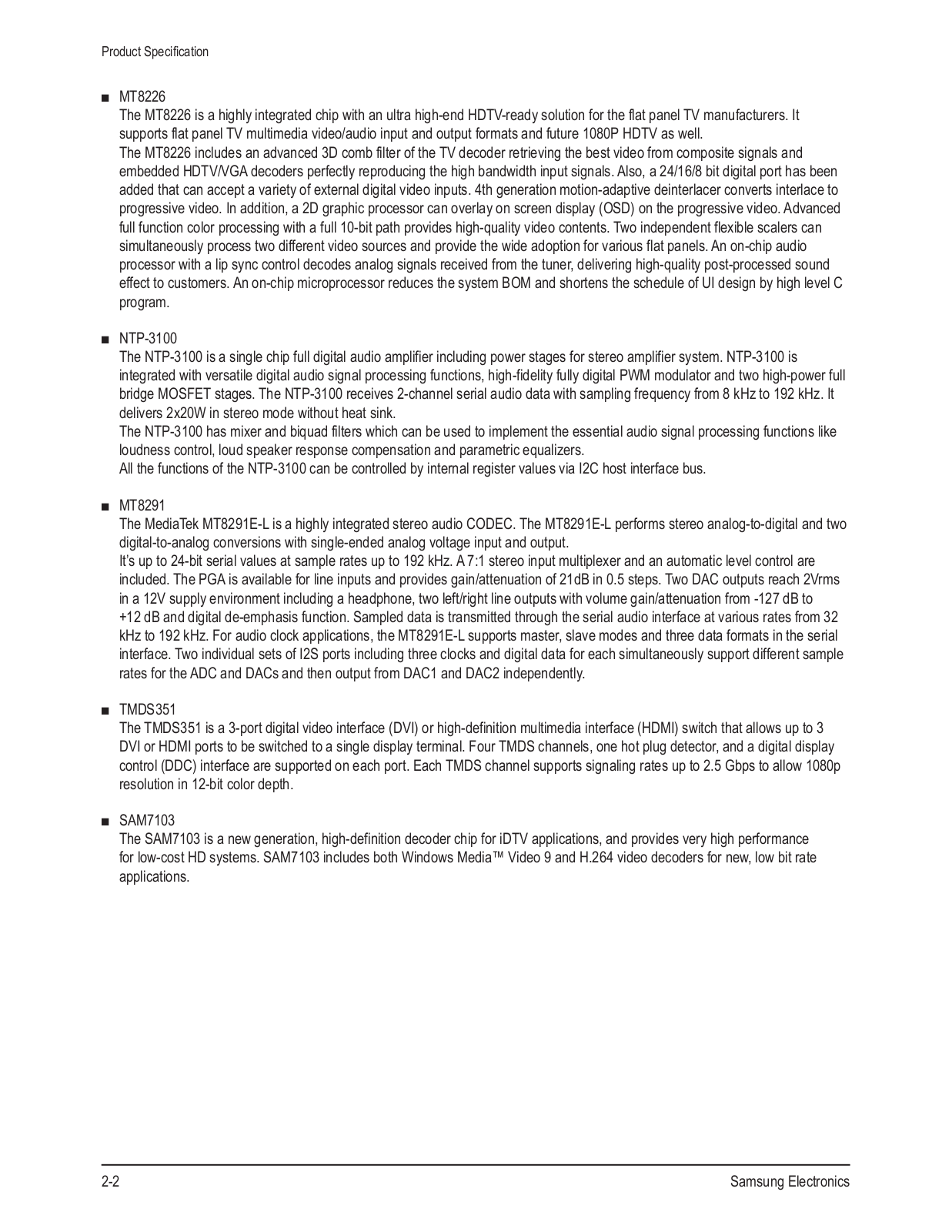
Samsung
Loading...
P
PS50A476P1C
3
PS50A476P1D
2
PS50A486P1M
PS50A486P1W
2
PS50A550
11
PS50A550S1F
2
PS50A550S1R
PS50A550S2R
13
PS50A550S2RXXC
PS50A551
4
PS50A551S2R
PS50A551S3
2
PS50A551S3R
10
PS50A552
PS50A552S
2
PS50A552S1R
14
PS50A556
9
PS50A556S2C
3
PS50A556S2F
9
PS50A557
9
PS50A557S3C
3
PS50A557S3F
10
PS50A557S3Fxxc1
PS50A558
3
PS50A558S1C
3
PS50A558S1F
5
PS50A558S1FXRU
PS50A566
3
PS50A566S2M
PS50A566S2MXZF
PS50A566S2W
4
PS50A567
PS50A567S3M
PS50A567S3W
5
PS50A568
PS50A568S1M
2
PS50A568S1W
5
PS50A650
8
PS50A650T1F
2
PS50A650T1R
3
PS50A656
10
PS50A656T1F
12
PS50A676
3
PS50A676T1
2
PS50A676T1M
PS50A676T1W
3
PS50A750
2
PS50A750T1F
PS50A756
8
PS50A756T1M
4
PS50A756T1MXXH
PS50A756T1W
PS50A766
PS50A766T1
2
PS50A766T1W
4
PS50B430
3
PS50B430P
2
PS50B430P2
4
PS50B430P2W
7
PS50B435
2
PS50B435P2W
2
PS50B450
8
PS50B450B
PS50B450B1
4
PS50B450B1M
2
PS50B450B1W
7
PS50B451
7
PS50B451B
PS50B451B2W
4
PS50B451B2WXXC
PS50B455
2
PS50B455B1W
2
PS50B456
2
PS50B456B2W
3
PS50B530
4
PS50B530S2W
6
PS50B530S2WXXC
PS50B535
2
PS50B535S2W
2
PS50B550
7
PS50B550T
PS50B550T2F
PS50B550T2M
PS50B550T2R
5
PS50B550T4P
PS50B550T4W
4
PS50B551
4
PS50B551T
PS50B551T3P
PS50B551T3W
8
PS50B555
2
PS50B555T4W
3
PS50B556
PS50B556T3W
PS50B560
PS50B560T7P
PS50B560T7W
3
PS50B565
PS50B565T7W
3
PS50B579T6S
Loading...
Loading...
Nothing found
PS50A756T1MXXH
Schematic
78 pgs
30.34 Mb
0
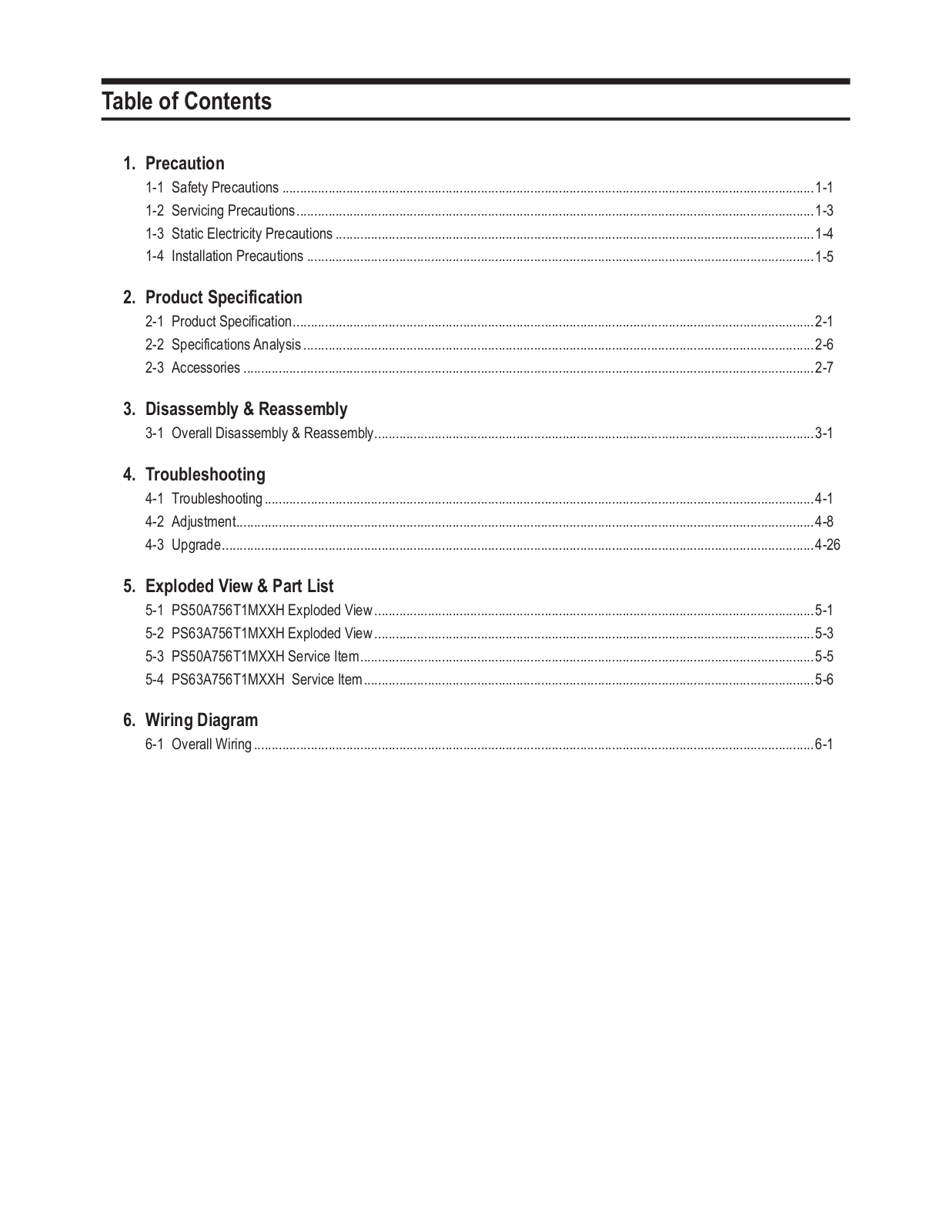
Table of contents
Loading...
Samsung PS50A756T1MXXH Schematic
...
Samsung Schematic
Download
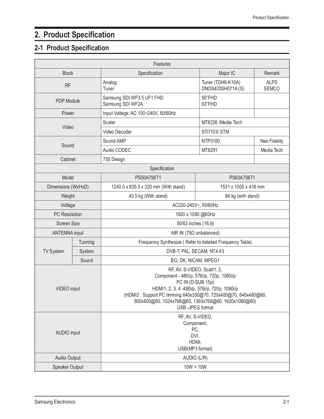
Specifications and Main Features
Frequently Asked Questions
User Manual
Download
Loading...
+
54
hidden pages
Unhide
You need points to download manuals.
1 point = 1 manual.
You can buy points or you can get point for every manual you upload.
Buy points
Upload your manuals
 Loading...