

Page 1

SAMSUNG PROJECTION TV SERVICE GUIDE
*Supercedes and appends service manual data*
Covers Models: (P51 Chassis)
PCJ612R/PCJ 522R (covers PCK520)
PCJ533R
PCJ533RF
PCJ534RF (covers PCJ532RF, PCK5315R)
PCJ614RF (covers PCJ611RF, PCK6115R)
HCJ552W/HCJ652W
Last update: 3/14/01
Page 2

SAMSUNG PROJECTION TV SERVICE GUIDE
Table of Contents
Sections
1. How to Use This Guide
2. Service Bulletins
3. Flow Charts/Micro Kits
4. Macro Kit Instructions
5. Parts Data
6. Assembly/Disassembly
7. Escalation/Who to Call
Last update: 3/14/01
Page 3

SAMSUNG PROJECTION TV SERVICE GUIDE
Section 1 - How to Use This Guide
How to use this Guide
This guide is divided into seven sections. Start with the section marked
“Instructions”.
The models covered in this document are derived from the P51A chassis. However; this
chassis has several different versions that are NOT covered in the service manuals.
Instructions to Start Service:
1. Obtain model, serial and symptom.
2. Review service bulletins (section 2), for common fixes. If Service Bulletin states that
repair is common, complete repair as indicated. Otherwise, proceed to section 3.
3. Review symptom/repair list as per the micro kit section (3). Order part number for
“kit” or individual parts.
Important Note: Order MACRO Kit only when technically required or the individual boards are
not available as an additional 45 minutes to 1 hour is needed for convergence, alignments and
other configuration setup.
4. If the previous steps do lead to a clear diagnosis, then proceed to the flow chart in
section 3 to help assist you in determining the correct PCB’s to order.
5. Place order through Samsung Parts Department.
Note: Distributors DO NOT carry PCB’s or macro kits, so backorder with
no eta will result. Parts Department will not accept an order for PTV parts without a
serial number because correct ID cannot be assured.
6. Parts will automatically ship 2nd day or faster. It is essential that the macro kit be
returned A.S.A.P. Your account will be charged, depending on the kit, up to
$1500.00 if the kit is not returned within 30 days.
7. When installing parts (refer to section 6 - Assembly/Disassembly), repair alignment
or adjustment will be necessary. There are three adjustment modes:
Convergence – to enter, press “Mute 183”
Geometric; Color Temp, etc. – to enter, press “Mute 182”
Geometric 1080i mode (DTV ready sets only, PCJ534RF, PCJ532RF, PCK5315R,
PCJ614RF, PCJ611RF, PCK6115R, HCJ552W/HCJ652W) - Refer to Service Bulletin
Follow detailed Alignment/Adjustment instructions in the service manual or the macro kit
instruction sheets.
Last update: 3/14/01 1
Page 4

SAMSUNG PROJECTION TV SERVICE GUIDE
Section 1 - How to Use This Guide
Important Points:
1. Most adjustments can be made using the remote control. However, in certain cases,
a “special remote” is required. This remote is included with each macro kit except the
PCJ522R series (not required). If you need this special remote you can order it from
Parts Department. (refer to section 2, service bulletin)
2. Option Byte: The firmware controlling the microprocessor may need to be changed
after Main PCB or Macro Kit is replaced. This is done by setting the option bytes.
Improper setting can cause symptoms including improper audio operation, menu
selections, or mechanical operations of the control panel door. Refer to the service
bulletin for correct settings.
3. The DTV input will not be recognized unless a DTV signal is applied to the
component input before DTV mode is selected.
4. Macro Kits are universal, PCB’s are not. A macro kit can be used for any version
replacement within the same model group. However; all macro kits are the newest
version, which may require the connectors be modified to ensure compatibility with the
CRT PCB connectors (refer to section 3).
5. Screen Replacement: Samsung PTV utilizes 2 screens; an outer Sunscreen and an
inner Tint Screen (Fresnel & Lenticular) sandwiched together. FYI, some models do not
have a Sun Screen. To order either of these screens under warranty, contact
Product/Technical Support for authorization. Note the name of the individual authorizing
the replacement for future reference, if needed.
6. CRT Burns: Permanent “burn ins” can occur if the set is used in any mode where
the screen is always dark or a screen image is static. This requires replacement of all
three CRT’s. Contact your RSE on how to handle this service. This is normally not
covered by warranty, so special approval must be granted.
7. Auto Mileage: We will pay $0.50 per mile travel time without special approval, up to
50 additional miles beyond the 25 miles required by contract. However; you must
provide proof, such as Internet driving directions or similar verifiable map and attach it to
the claim when submitted.
8. Macro Kits are always version 1 chassis. This means if an older version unit
previously had a Macro kit installed, parts ID via the serial number will be invalid.
Chassis version can be identified by the color of the connectors. White = original
version, black = version 1.
9. Returned parts: All parts must be returned with a description of the defect attached.
Failure to do so will result in delay in processing and credit. Also, include one copy of
the NARDA so warranty status can be confirmed.
Last update: 3/14/01 2
Page 5

SAMSUNG PROJECTION TV SERVICE GUIDE
Section 2 - Service Bulletins
SERVICE BULLETIN
PRODUCT: PJT
NO: PJT01
MODEL: HCJ552W / PCJ532RF / PCJ534RF
SUBJECTS: Up-Grade (R802)
BACKGROUND: When you received defect Projection TV, please check R802.
If R802 is green color, change R802 as per parts list.
* R802 is located in Main Board
SOLUTION: 1. Check R802
2. If R802 is 4.75 ohm/3.85A(green color thermistor)
3. Change component.
Before (code no) After (code no)
R802 4.7ohm/3.85A(1404-001075) 4.7ohm/4.64A(1404-
PCJ612R / PCJ614R / PCJ522R
001045)
Last update: 3/14/01 3
Page 6

SAMSUNG PROJECTION TV SERVICE GUIDE
Section 2 - Service Bulletins
Operation Tip
PRODUCT: PJT
BULLETIN: PJT02
MODEL: HCJ652W & HCJ552W
Subject: Changing the aspect ratio of
screen
Background: The screen aspect ratio can be displayed in two ways,
4 x 3 or 16 x 9.
Countermeasure: Using the customer remote, the aspect ratio can be changed.
Press the MENU botton to display the main menu. Using the channel down botton, high
lite “SET UP“, press volume + botton. Use the channel down botton to high lite
“CONVERGENCE”, press volume + botton. Use the channel down botton to high -lite
“SCREEN SIZE”. Press volume + botton to toggle between normal (4x3) and wide
(16x9).
Last update: 3/14/01 4
Page 7

SAMSUNG PROJECTION TV SERVICE GUIDE
Section 2 - Service Bulletins
SERVICE BULLETIN
PRODUCT: PJT
BULLETIN: PJT03
Subject: Compatibility of PCB connectors
Background: PCB replacement parts have two types of connectors. If the part you
received has a white connector (no wires), a countermeasure may need to be done.
Countermeasure: The black plug connector (wires attached) needs to be modified.
Cut tabs (ears) off black connectors. This will make the connection compatible.
MODEL: All Models with PCJ/K or HCJ
Last update: 3/14/01 5
Page 8
SAMSUNG PROJECTION TV SERVICE GUIDE
Section 2 - Service Bulletins
SERVICE BULLETIN
PRODUCT: PJT
BULLETIN: PJT04
MODEL: PCJ534RF, PCJ532RF, PCK5315R
PCJ614RF, PCK6115R, PCJ611RF
Subject: Service Remote for 1080I adjustments.
Background: A special service remote is needed to access the geometric, picture and
other 1080I adjustments.
Countermeasure: Order remote using part # AA59-00055A.
To access 1080I service adjustment mode, use the following procedure.
1. Connect 1080I signal to DTV jacks on rear panel of set.
2. Press DTV button on remote, OSD will display “DTV mode”.
3. Press DISPLAY button on remote and then press FACTORY button on remote.
Service adjustment mode for 1080I will be displayed.
4. Select item by using channel up/down; then press volume +.
5. Service adjustment mode control buttons:
Back to main menu Menu button
Select adjustment location Channel up/down buttons
Increase or Decrease adjustment value Volume up/down buttons
Save data Automatic, power off.
6. Refer to service manual (page 4-4) for details on 1080I adjustment.
HCJ552W, HCJ652W.
Last update: 3/14/01 6
Page 9

SAMSUNG PROJECTION TV SERVICE GUIDE
Section 2 - Service Bulletins
SERVICE BULLETIN
PRODUCT: PJT
BULLETIN: PJT05
MODE: all models with PCJ/K or HCJ
Subject: Screen shows circular mark, size can be up to three inches in diameter.
Background: Moisture or dirt has accumulated between the Lenticular and Fresnel
screens. The Tint screen consists of Lenticular / Fresnel screens, these two screens
must be separated and cleaned.
Countermeasure:
a) Remove front panel, which on some models is held by screws, and on other
models is not. Panel must be separated by carefully pulling seam apart. (Model
PCJ534RF has this type of design).
b) Remove Tint screen, screen is supported on four sides by metal brackets.
c) Remove tape around Tint screen. Save tape, if new tape is needed use black
cloth tape, not electrical tape. Separate Lenticular / Fresnel screens.
d) Clean screens using rubbing alcohol and lens cleaning cloth (lint free). When
cleaning, use circular motion.
e) Reassemble, be sure to re-tape tint screen edges.
f) If problem is still present, replace Tint screen.
Last update: 3/14/01 7
Page 10

SAMSUNG PROJECTION TV SERVICE GUIDE
Section 2 - Service Bulletins
SERVICE BULLETIN
PRODUCT: PJT
BULLETIN: PJT06
MODE: all models with PCJ/K or HCJ
Subject: Option byte settings.
Background: Check option byte setting in factory mode.
Countermeasure: Chart shows option bytes setting. Check production date for
version.
Model Early version New version
Byte 00 Byte 01 Byte 00 Byte 01
PCJ522R 91 00 91 01
PCK520R 91 00 91 01
PCJ612R 91 00 91 01
PCJ533R 11 50 71 50
PCJ533RF 11 54 71 40
PCJ534RF 11 44 71 44
PCJ532RF 11 44 71 44
PCK5315R 11 44 71 44
PCJ614RF 11 44 71 44
PCJ611RF 11 44 71 44
PCK6115R 11 44 71 44
HCJ652W 19 41 79 41
HCJ552W 19 41 79 41
Last update: 3/14/01 8
Page 11
SAMSUNG PROJECTION TV SERVICE GUIDE
Section 3 - Flow Charts/Micro Kits
Last update: 3/14/01 9
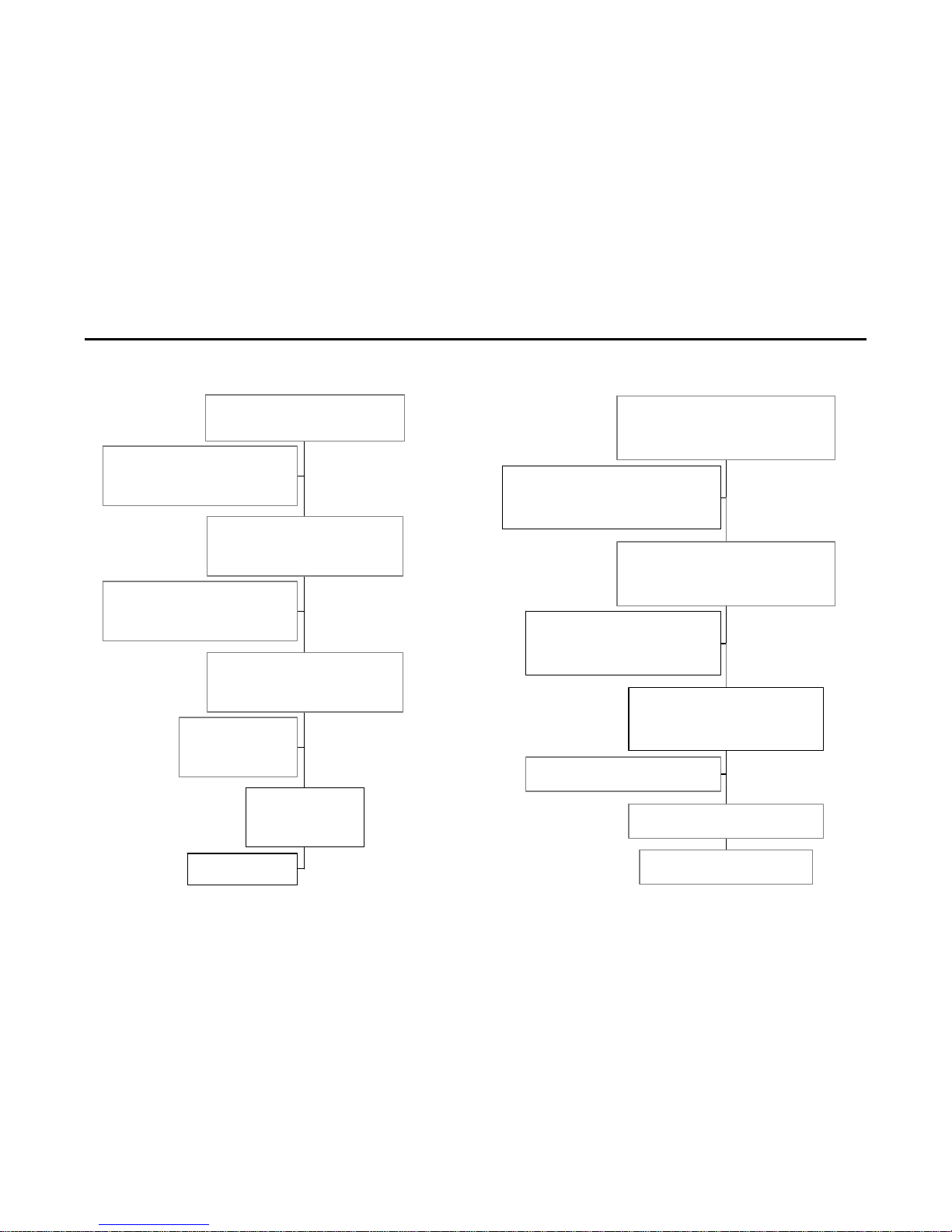
power repair flow chart
"missing"
change sub pcb
"missing"
change main pcb
"missing"
change main pcb
"missing"
change sub pcb
"120 volts ac ok"
supply voltage
CN801 pin 6
117 volts dc
"stb 5 volts ok"
power control
120 volts ac
CN809 pins GT813 & GT814
"ac voltage ok"
stb 5 volts
IC902 pin 8
5 volts dc
120 volt ac
CN809 pins GT801 & GT 803
120 volts ac
convergence repair flow chart
"missing"
change sub pcb
"missing"
change sub pcb
"missing"
change main pcb
"convergence data module ok'
change convergence amp pcb
"BLK pulse ok"
change convergence data module
"6 volts ok"
vertical and horizontal BLK
CN203 pin 10 vertical BLK pulse
CN203 pin 9 horizontal BLK pulse
"30 volts ok"
convergence data supply voltage
CN802 pins 13 and 15
pin 13 = -6 volts dc, pin 15 = 6 volts dc
convergence amp supply voltage
CN802 pins 16 and 18
pin 16 = -30 volts dc
pin 18 = 30 volts dc
Page 12
SAMSUNG PROJECTION TV SERVICE GUIDE
Section 3 - Flow Charts/Micro Kits
Last update: 3/14/01 10
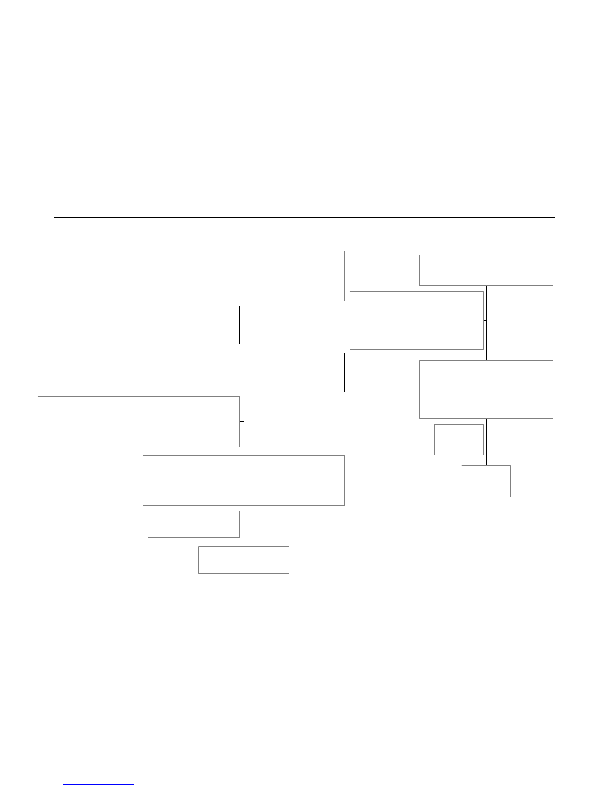
audio repair flow chart
"missing"
change sub pcb
"missing"
change main pcb
"audio signal ok"
check speakers
"34 volts ok"
audio signals at CN601
adjust audio level and signal level should change
CN601 pin 1 "L", pin 3 "R",
audio power supply voltages
CN80 pin 1, 34 volts dc
video repair flow chart
"missing"
change sub pcb
"missing"
change sub pcb
"missing"
change H/V module
"CRT supply volts ok"
change CRT pcb
"31 KV ok"
CRT supply voltages
CN401 pin 1 = 208 volt, pin 4 = 6.3 volts (heater)
pin 6 = 12 volts dc
"13.5 & 8.5 volts ok"
High Voltage
check CRT anode voltages 31 KV
video process supply voltage
CN801 pins 1 and 4
pin 1 = 13.5 volts dc
pin 4 = 8.5 volts dc
Page 13
SAMSUNG PROJECTION TV SERVICE GUIDE
Section 4 - Micro Kit Instructions
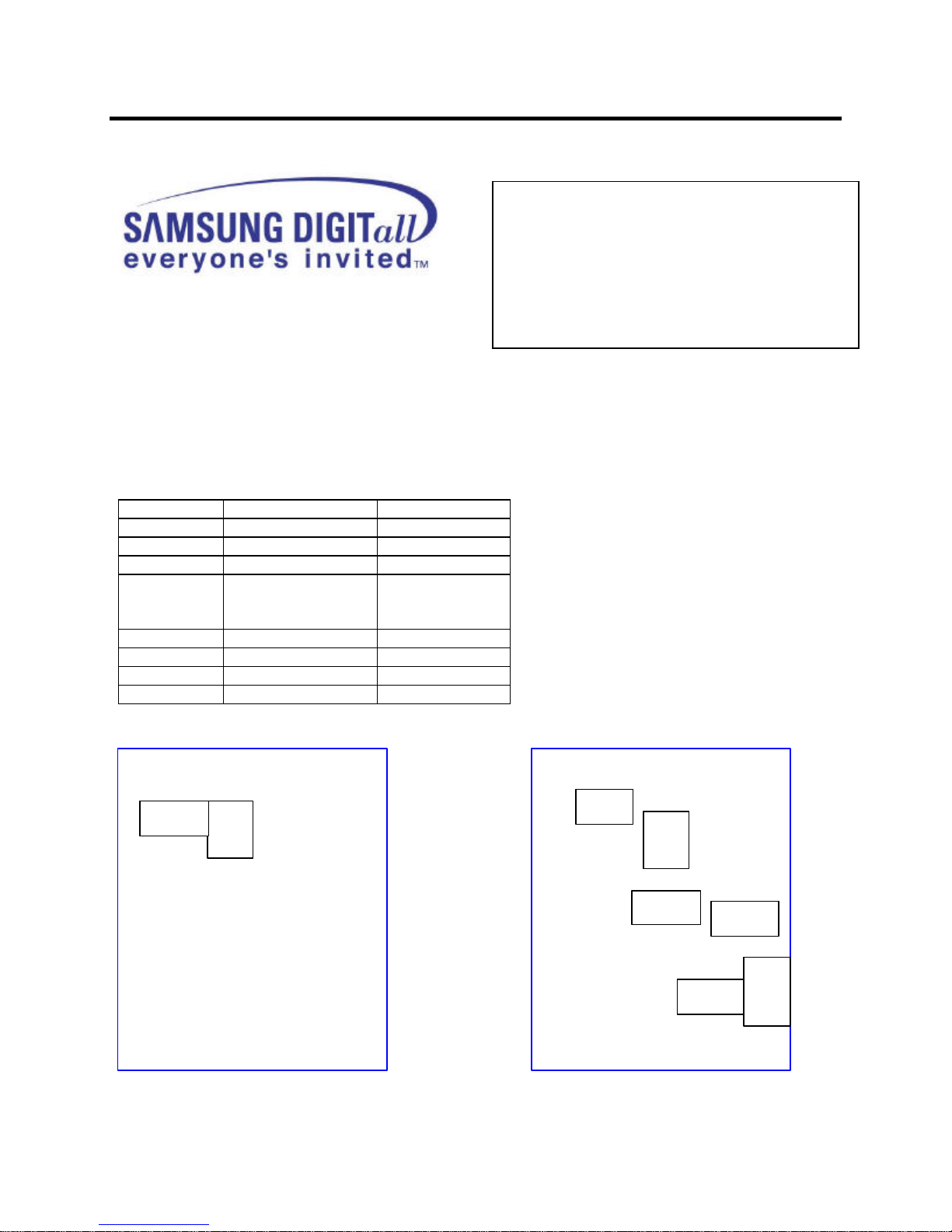
Micro Kit P51A Chassis
Subject: PCB field repair kit
Countermeasure: Perform all steps in order listed
1. Check R440, if open order / replace H / V module and Sub pcb.
2. Check PCB’S for cracks, bad solder connections or bridges.
3. Check symptom, replace appropriat e part.
a) No audio, replace F854
b) No picture, has sound, replace Q473 / R465 / DZ481.
c) No power, replace F802 / IC902 / X901. Use flow charts and check voltages.
Location # Part Number Desc
IC902 1103-001105 Main pcb
X901 2801-003224 Main pcb
Q473 0502-001100 Sub pcb
R46
5
2008-001091 Sub pcb
PRODUCT: PJT
PART NUMBER: ST-#CJ KIT
MODEL: PCJ522R, PCK520R,
PCJ533R, PCJ533RF, PCJ534RF,
PCJ614RF, PJC532RF, PCK5315R,
PCK6115R, PCJ611RF, HCJ552W,
HCJ652W, PCJ612R.
R440 2008-001091 Sub pcb
DZ481 0403-000658 Sub pcb
F802 3601-001137 Sub pcb
F854 3601-001086 Sub pcb
Use figures to find component location
Main pcb Sub pcb
IC902
X901
F802
F854
R465
Q473
R440
DZ481
Last update: 3/14/01 11
Page 14

SAMSUNG PROJECTION TV SERVICE GUIDE
Section 4 - Micro Kit Instructions
Note: There are several versions of this chassis; some PCBs are not interchangeable
with PCBs of other versions. It is therefore imperative the chassis be changed as a unit
and adjusted as described below.
1. Remove and reinstall chassis by following instructions in service manual
2. On some versions the CRT PCB connectors may have to be modified to attach to
the replacement chassis. If the female part of the connector is black, clip the locking
tabs (ears) on both sides bef ore inserting plug.
3. Remove back panel containing rating label from the defective chassis and reinstall it
on the replacement.
4. Perform all necessary geometric and convergence adjustments.
5. Repack defective chassis in the same way as it was received in shipping container
along with original packing list and copy of NARDA form.
Return to:
Samsung Parts Dept.
18600 Broadwick St.
Rancho Dominguez, CA 90220
1-800-634-8276
Important! Read First
PRODUCT: PJT
MODEL: PCJ522R, PCK520R, PCJ612R
PCJ533R, PCJ533RF
Change chassis as a unit, do not swap
individual PCB (see note below).
Last update: 3/14/01 12
Page 15

SAMSUNG PROJECTION TV SERVICE GUIDE
Section 4 - Micro Kit Instructions
Subject: Instruction for Service Kit installation and Processing
Note: There are several versions of this chassis; some PCBs are not interchangeable with PCBs of other
versions. It is therefore imperative the chassis be changed as a unit and adjusted as described below.
1. Remove and reinstall chassis by following instructions in service manual.
Important! Read First
PRODUCT: DTV
MODEL: PCJ534RF, PCJ532RF, PCK5315R
PCJ614RF, PCK6115R, PCJ611RF
HCJ552W, HCJ652W
Change chassis as a unit, do not swap
individual PCB (see note below).
2. On some versions the CRT PCB connectors may have to be modified to attach to the
replacement chassis. If the female part of the connector is black, clip the locking tabs (ears) on
both sides before inserting plug.
3. Remove back panel, containing rating label, from the defective chassis and reinstall it on the
replacement.
4. Adjust F/S voltage for 2.25V +/- .01 at J120 with VR472 on Convergence Board.
Shield
Convergence Board
J120
VR472
5. Perform all necessary geometric and convergence adjustments.
Note:
• Set Top Box Adjustment, If set top box is used (1080i mode) perform
procedure described in service bulletin
6. Repack defective chassis in the same way as it was received in shipping container along with
original packing list and copy of NARDA form.
Return to:
Samsung Parts Dept.
18600 Broadwick St.
Rancho Dominguez, CA 90220
1-800-634-8276
Last update: 3/14/01 13
Page 16

SAMSUNG PROJECTION TV SERVICE GUIDE
Section 5 - Parts Data
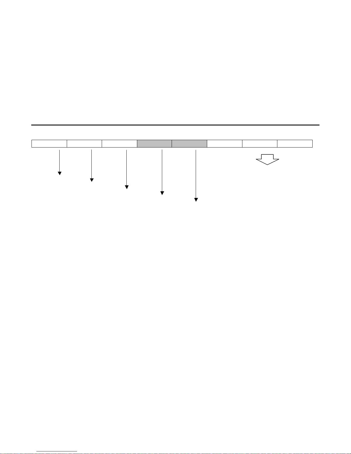
How to get the correct parts the first time!
The parts table in section 5 is based on the production date (DOM=Date of Manufacture). This
must be determined before referencing parts data. DOM can be determined through the 4th
and 5th digit of the serial number by using the illustration provided (section 5). From there, you
can select the correct parts table according to the month/year bars.
Example:
Part needed; Main PCB for Model HCJ552W. Serial Number 3CEN700912X.
Step 1 – Locate table for HCJ552W in section 5.
Step 2 – Reference 4th and 5th digit of serial # = “N 7” which transl ates to July 2000.
Step 3 – Look up Main PCB under appropriate month/year, part number is AA94-02600B.
Parts Assembly Levels
There are three parts assembly levels:
1. Micro Kit – a small collection of component level parts along with a symptom/repair listing.
Locate the micro kit part number in section 3.
2. PCB Level – individual major PCB’s which comprise the bulk of the functional chassis.
Locate individual PCB part numbers in section 5.
3. Macro Kit – the major PCB’s pre-mounted and connected on the chassis rail is supplied as
a single unit. Locate macro kit part number in section 5.
Last update: 3/14/01 14
Page 17
SAMSUNG PROJECTION TV SERVICE GUIDE
Section 5 - Parts Data
Last update: 3/14/01 15
X 1 C K 6 NN NN NX
5 DIGITS AND A LETTER
DIVISION
FACTORY
PROD LINE
YEAR
MONTH
A : 1991 1=JANUARY
B : 1992 2=FEBRUARY
C : 1993 3=MARCH
D : 1994 4=APRIL
E : 1995 5=MAY
F : 1996 6=JUNE
G : 1997 7=JULY
J : 1998 8=AUGUST
K : 1999 9=SEPTEMBER
N : 2000 A=OCTOBER
R : 2001 B=NOVEMBER
T : 2002 C=DECEMBER
Important Note: Order MACRO Kit only when technically required or the individual boards are not available as an additional 45 minutes to 1
hour is needed for convergence, alignments and other configuration setup
Page 18
SAMSUNG PROJECTION TV SERVICE GUIDE
Section 5 - Parts Data
Last update: 3/14/01 16
PCJ522RX/PCK520R/PCJ612RFX - Macro Kit Part # MKPCJ522RX
Dec-99 Jan-00
May-00
Jun-00
TYPE
PART#
PART# TYPE
MAIN PCB
AA94-01636A
AA94-01636E
MAIN PCB
SUB
AA95-00053F ASK FOR SERIAL NUMBER
AA95-00053Y
SUB
CONVERGENCE
AA95-00055E
AA95-00055K
CONVERGENCE
H/V
AA95-00056D
AA95-00056G
H/V
CONV. MODULE
AA95-00478A
AA95-00422A
CONV. MODULE
PCJ534RF - Macro Kit Part # MKPCJ534RF
PCK5315R,6115R / PCJ614RF3C (BEST BUY MODEL) - Macro Kit Part # MKPCK5315R
Dec-99 Jan-00
May-00
Jun-00
TYPE
PART# PART# TYPE
MAIN PCB
AA94-01427C,V
MAIN PCB
AA94-01248A AA94-01290C
AA94-02599D
MAIN PCB
SUB
AA95-00053A AA95-00053V
AA95-00691A
SUB
CONVERGENCE
AA95-
AA95-00055H
AA95-00692A
CONVERGENCE
H/V
AA95-00056A AA95-00056E (X)
AA95-00696A
H/V
CONV. MODULE
AA95-00157A AA95-00157B
AA95-00422D
CONV. MODULE
HCJ552W - Macro Kit Part # MKHCJ552W
Dec-99 Jan-00
May-00
Jun-00
TYPE
PART# PART# TYPE
MAIN PCB
AA94-01247A AA94-01247D,E
AA94-02600B
MAIN PCB
SUB
AA95-00308A (X) AA95-00053V
AA95-00691A
SUB
CONVERGENCE
X
AA95-00055H
AA95-00692A
CONVERGENCE
H/V
AA95-00309A (X) AA95-00056E (X)
AA95-00696A
H/V
CONV. MODULE
X
AA95-00157B
AA95-00422D
CONV. MODULE
HCJ652W - Macro Kit Part # MKHCJ652W
Dec-99 Jan-00
May-00
Jun-00
TYPE
PART# PART# TYPE
MAIN PCB X
AA94-01247B
AA94-02600D
MAIN PCB
SUB
AA95-00325A AA95-00325A
AA95-00691E,A
SUB
CONVERGENCE
X
AA95-00055H
AA95-00692A
CONVERGENCE
H/V X
AA95-00056F
AA95-00696B,A
H/V
CONV. MODULE
X
AA95-00157E
AA95-00157E
CONV. MODULE
Page 19
SAMSUNG PROJECTION TV SERVICE GUIDE
Section 5 - Parts Data
Last update: 3/14/01 17
PCJ533R - Macro Kit Part # MKPCJ533R
Dec-99 Jan-00
May-00
Jun-00
TYPE
PART# PART# TYPE
MAIN PCB
AA94-10154P
AA94-01290J
AA94-02599A
MAIN PCB
SUB
AA95-00053A
AA95-00053V
AA95-00691A
SUB
CONVERGENC
AA95-0055A,B,C
AA95-00055H
AA95-00692A
CONVERGENCE
H/V
AA95-00056A
AA95-00056E (X)
AA95-00696A
H/V
CONV. MODULE
AA95-00157A
AA95-00157B
AA95-00422D
CONV. MODULE
PCJ533RF
Dec-99 Jan-00
May-00
Jun-00
TYPE
PART# PART# TYPE
MAIN PCB
AA94-01427A
AA94-01290G (X)
AA94-02599C
MAIN PCB
SUB
AA95-00053B
AA95-00053V
AA95-00691A
SUB
CONVERGENC
AA95-0055A,B,C
AA95-00055H
AA95-00692A
CONVERGENCE
H/V
AA95-00056A
AA95-00056E (X)
AA95-00696A
H/V
CONV. MODULE
AA95-00157A
AA95-00157B
AA95-00422D
CONV. MODULE
PCJ614RF - Macro Kit Part # MKPCJ614RF
Dec-99 Jan-00
May-00
Jun-00
TYPE
PART# PART# TYPE
MAIN PCB
AA94-01290A
MAIN PCB
AA94-01427D
AA94-1290X(X)F,E
AA94-02599G
MAIN PCB
SUB
AA95-00053B
AA95-00053V
AA95-00691A
SUB
CONVERGENC
AA95-0055A,B,C
AA95-00055H
AA95-00692A
CONVERGENCE
H/V
AA95-00056A
AA95-00056E (X)
AA95-00696A
H/V
CONV. MODULE
AA95-00157A
AA95-00157B
AA95-00422D
CONV. MODULE
PCJ611RF - Macro Kit Part # MKPCJ611R
Dec-99 Jan-00
May-00
Jun-00
TYPE
PART# PART# TYPE
MAIN PCB
AA94-01290B
AA94-01290F,E
AA94-02599(J)X
MAIN PCB
SUB
AA95-00053B
AA95-00053V
AA95-00691A
SUB
CONVERGENC
AA95-0055A,B,C
AA95-00055H
AA95-00692A
CONVERGENCE
H/V
AA95-00056A
AA95-00056E (X)
AA95-00696A
H/V
CONV. MODULE
AA95-00157A
AA95-00157B
AA95-00422D
CONV. MODULE
Page 20
SAMSUNG PROJECTI ON TV SERVICE GUIDE
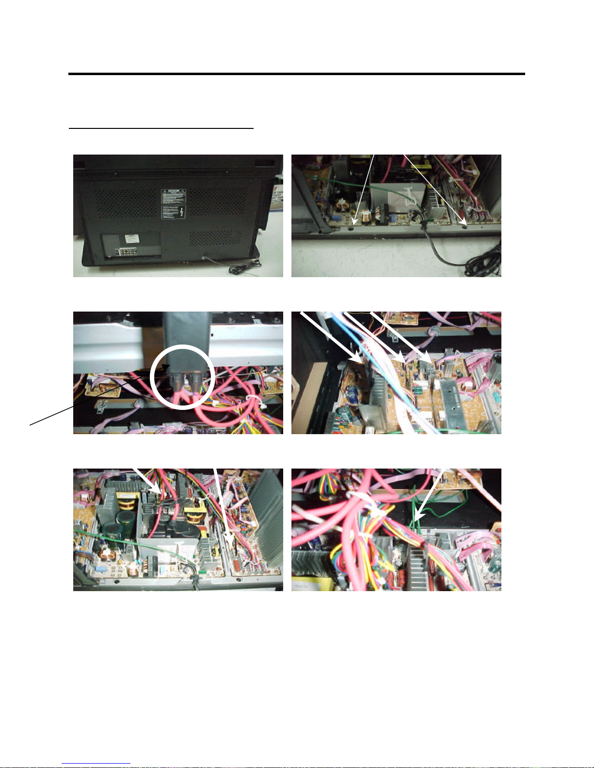
Section 6 – Assembly/Disassembly
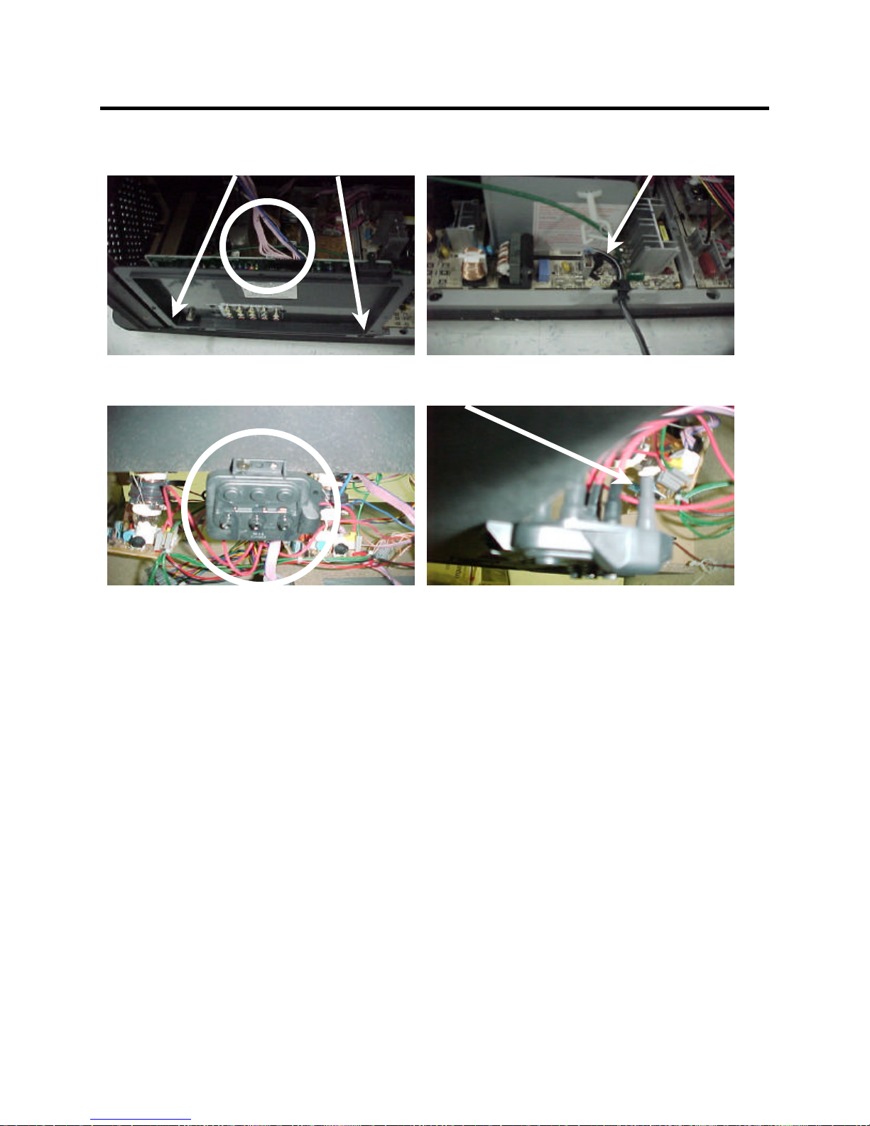
Disassembly Procedure
1. Open bottom cabinet
3.Unplug High Voltage Connector
5. Unplug Def Yoke & Conv Yoke connector
2.Unscrew Holder-bracket
4.Unplug 3 connectors
6.Unplug 3 Green GND Connector
Last update: 3/14/01 18
Page 21
SAMSUNG PROJECTI ON TV SERVICE GUIDE
8 Unplug Power Connector
10. Unplug the Focus Cable from
Section 6 – Assembly/Disassembly
7.Unplug Connector and unscrew
9. Unplug the Focus Cable from FBT
11.Exchange Macro Kit
Last update: 3/14/01 19
Page 22

SAMSUNG PROJECTION TV SERVICE GUIDE
Section 7 - Escalation/Who to Call
Escalation Paths and Technical Support
1. Parts Issues
If wrong or defective parts are received, contact Parts Department with the invoice or
PO numbers to resolve.
If the parts do not fix the problem and you need technical assistance:
973-601-6124 between 9:00 – 5:30 EST
2. Regional Service Engineers are available for each geographic region. They are your
key contact for all technical and policy related issues that cannot be resolved through
normal means. Their regions and phone numbers:
West Zone: Jeff Reeves 310-537-7000 x131
Mid-West Zone: Mark Rowland 630-879-1401
East Zone: Anthony Ippolito 973-601-6005
South Zone: Dan Girdley 678-560-9140
3. Website: www.samsungasc.com
a. Logon: ID = your account number
Password = your zip code
Our ASC website contains most service manuals in PDF format ready for download.
To use these files you need Adobe Acrobat Viewer which can be downloaded for
free @ www.adobe.com. This site also contains other support data; i.e. service
bulletins, BIOS files and our policy guide.
Last update: 3/14/01 20
Page 23

PROJECTION TV RECEIVER
Chassis : P51A
Model: HCJ652WX/XAA
PROJECTION TV RECEIVER CONTENTS
Precautions
Reference Information
Specifications
Alignment and Adjustments
Troubleshooting
Exploded View and Parts List
Electrical Parts List
Block Diagrams
Wiring Diagram
Schematic Diagrams
1.
2.
3.
4.
5.
6.
7.
8.
9.
10.
Page 24

ELECTRONICS
© Samsung Electronics Co., Ltd. JAN. 2000
Printed in Korea
3P51A-6501
Page 25
1. Precautions
1-1 Safety Precautions
1. Be sure that all of the built-in protective
devices are replaced. Restore any missing
protective shields.
2. When reinstalling the chassis and its
assemblies, be sure to restore all protective
devices, including: nonmetallic control knobs
and compartment covers.
3. Make sure that there are no cabinet openings
through which peopleÑparticularly
childrenÑmight insert fingers and contact
dangerous voltages. Such openings include
the spacing between the picture tube and the
cabinet mask, excessively wide cabinet
ventilation slots, and improperly fitted back
covers.
If the measured resistance is less than 1.0
megohm or greater than 5.2 megohms, an
abnormality exists that must be corrected
before the unit is returned to the customer.
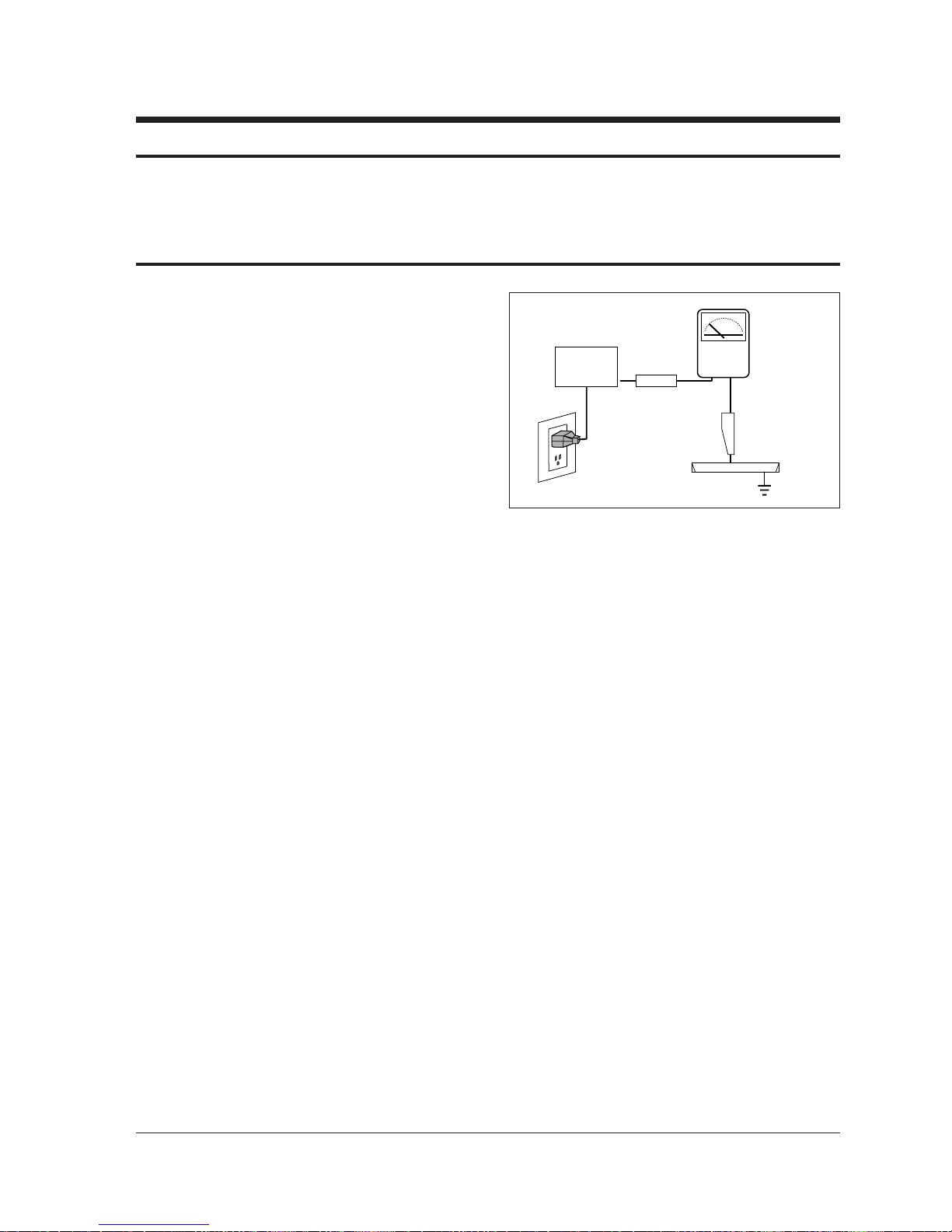
4. Leakage Current Hot Check (Figure 1-1):
Warning: Do not use an isolation
transformer during this test. Use a leakagecurrent tester or a metering system that
complies with American National Standards
Institute (ANIS C101.1, Leakage Current for
Appliances), and Underwriters Laboratories
(UL Publication UL1410, 59.7).
5. With the unit completely reassembled, plug
the AC line cord directly into the power
outlet. With the unitÕs AC switch first in the
ON position and then OFF, measure the
current between a known earth ground (metal
water pipe, conduit, etc.) and all exposed
metal parts, including: antennas, handle
brackets, metal cabinets, screwheads and
control shafts. The current measured should
not exceed 0.5 milliamp. Reverse the powerplug prongs in the AC outlet and repeat the
test.
Fig. 1-1 AC Leakage Test
6. Antenna Cold Check:
With the unitÕs AC plug disconnected from the
AC source, connect an electrical jumper across
the two AC prongs. Connect one lead of the
ohmmeter to an AC prong. Connect the other
lead to the coaxial connector.
7. X-ray Limits:
The picture tube is especially designed to prohibit X-ray emissions. To ensure continued
X-ray protection, replace the picture tube only
with one that is the same type as the original.
Carefully reinstall the picture tube shields and
mounting hardware; these also provide X-ray
protection.
8. High Voltage Limits:
High voltage must be measured each time servicing is done on the B+, horizontal deflection
or high voltage circuits. Correct operation of
the X-ray protection circuits must be
reconfirmed whenever they are serviced.
(X-ray protection circuits also may be called
Òhorizontal disableÓ or Òhold-downÓ.)
Heed the high voltage limits. These include
the XÐray Protection Specifications Label, and
the Product Safety and X-ray Warning Note on
the service data schematic.
Precautions
Samsung Electronics 1-1
LEAKAGE
CURRENT
TESTER
DEVICE
UNDER
TEST
TEST ALL
EXPOSED METAL
SURFACES
3-WIRE CORD
ALSO TEST WITH
PLUG REVERSED
(USING AC ADAPTER
PLUG AS REQUIRED)
EARTH
GROUND
(READING SHOULD
NOT BE ABOVE
0.5mA)
Follow these safety, servicing and ESD precautions to prevent damage and protect against potential
hazards such as electrical shock and X-rays.
Page 26

1-1 Safety Precautions (Continued)
9. High voltage is maintained within specified
limits by close-tolerance, safety-related
components and adjustments. If the high
voltage exceeds the specified limits, check
each of the special components.
10. Design Alteration Warning:
Never alter or add to the mechanical or
electrical design of this unit. Example: Do not
add auxiliary audio or video connectors. Such
alterations might create a safety hazard. Also,
any design changes or additions will void the
manufacturerÕs warranty.
11. Hot Chassis Warning:
Some TV receiver chassis are electrically
connected directly to one conductor of the AC
power cord. If an isolation transformer is not
used, these units may be safely serviced only
if the AC power plug is inserted so that the
chassis is connected to the ground side of the
AC source.
To confirm that the AC power plug is inserted
correctly, do the following: Using an AC
voltmeter, measure the voltage between the
chassis and a known earth ground. If the
reading is greater than 1.0V, remove the AC
power plug, reverse its polarity and reinsert.
Re-measure the voltage between the chassis
and ground.
12. Some TV chassis are designed to operate with
85 volts AC between chassis and ground,
regardless of the AC plug polarity. These units
can be safely serviced only if an isolation
transformer inserted between the receiver and
the power source.
13. Some TV chassis have a secondary ground
system in addition to the main chassis ground.
This secondary ground system is not
isolated from the AC power line. The two
ground systems are electrically separated by
insulating material that must not be defeated
or altered.
14. Components, parts and wiring that appear to
have overheated or that are otherwise
damaged should be replaced with parts that
meet the original specifications. Always
determine the cause of damage or overheating, and correct any potential hazards.
15. Observe the original lead dress, especially
near the following areas: Antenna wiring,
sharp edges, and especially the AC and high
voltage power supplies. Always inspect for
pinched, out-of-place, or frayed wiring. Do
not change the spacing between components
and the printed circuit board. Check the AC
power cord for damage. Make sure that leads
and components do not touch thermally hot
parts.
16. Picture Tube Implosion Warning:
The picture tube in this receiver employs
Òintegral implosionÓ protection. To ensure
continued implosion protection, make sure
that the replacement picture tube is the same
as the original.
17. Do not remove, install or handle the picture
tube without first putting on shatterproof
goggles equipped with side shields. Never
handle the picture tube by its neck. Some
Òin-lineÓ picture tubes are equipped with a
permanently attached deflection yoke; do not
try to remove such Òpermanently attachedÓ
yokes from the picture tube.
18. Product Safety Notice:
Some electrical and mechanical parts have
special safety-related characteristics which
might not be obvious from visual inspection.
These safety features and the protection they
give might be lost if the replacement component differs from the originalÑeven if the
replacement is rated for higher voltage,
wattage, etc.
Components that are critical for safety are
indicated in the circuit diagram by shading,
( ) or ( ).
Use replacement components that have the
same ratings, especially for flame resistance
and dielectric strength specifications.
A replacement part that does not have the
same safety characteristics as the original
might create shock, fire or other hazards.
Precautions
1-2 Samsung Electronics
!
Page 27

1-2 Servicing Precautions
1. Servicing precautions are printed on the
cabinet. Follow them.
2. Always unplug the unitÕs AC power cord from
the AC power source before attempting to: (a)
Remove or reinstall any component or
assembly, (b) Disconnect an electrical plug or
connector, (c) Connect a test component in
parallel with an electrolytic capacitor.
3. Some components are raised above the printed
circuit board for safety. An insulation tube or
tape is sometimes used. The internal wiring is
sometimes clamped to prevent contact with
thermally hot components. Reinstall all such
elements to their original position.
4. After servicing, always check that the screws,
components and wiring have been correctly
reinstalled. Make sure that the portion around
the serviced part has not been damaged.
5. Check the insulation between the blades of the
AC plug and accessible conductive parts
(examples: metal panels, input terminals and
earphone jacks).
6. Insulation Checking Procedure: Disconnect the
power cord from the AC source and turn the
power switch ON. Connect an insulation
resistance meter (500V) to the blades of the AC
plug.
The insulation resistance between each blade
of the AC plug and accessible conductive parts
(see above) should be greater than 1 megohm.
7. Never defeat any of the B+ voltage interlocks.
Do not apply AC power to the unit (or any of
its assemblies) unless all solid-state heat sinks
are correctly installed.
8. Always connect a test instrumentÕs ground
lead to the instrument chassis ground before
connecting the positive lead; always remove
the instrumentÕs ground lead last.
9. When some parts inside the optical engine
(except lamp) are damaged, replace the whole
optical engine.
Precautions
Samsung Electronics 1-3
Warning 1 : First read the “Safety Precautions” section of this manual. If some unforeseen circumstance creates a
conflict between the servicing and safety precautions, always follow the safety precautions.
Warning 2 : An electrolytic capacitor installed with the wrong polarity might explode.
Page 28

1-3 Precautions for Electrostatically Sensitive Devices (ESDs)
1. Some semiconductor (Òsolid stateÓ) devices
are easily damaged by static electricity. Such
components are called Electrostatically
Sensitive Devices (ESDs); examples include
integrated circuits and some field-effect
transistors. The following techniques will
reduce the occurrence of component damage
caused by static electricity.
2. Immediately before handling any semicon
ductor components or assemblies, drain the
electrostatic charge from your body by
touching a known earth ground. Alternatively,
wear a discharging wrist-strap device. (Be
sure to remove it prior to applying powerÑ
this is an electric shock precaution.)
3. After removing an ESD-equipped assembly,
place it on a conductive surface such as
aluminum foil to prevent accumulation of
electrostatic charge.
4. Do not use freon-propelled chemicals. These
can generate electrical charges that damage
ESDs.
5. Use only a grounded-tip soldering iron when
soldering or unsoldering ESDs.
6. Use only an anti-static solder removal device.
Many solder removal devices are not rated as
Òanti-staticÓ; these can accumulate sufficient
electrical charge to damage ESDs.
7. Do not remove a replacement ESD from its
protective package until you are ready to
install it. Most replacement ESDs are
packaged with leads that are electrically
shorted together by conductive foam,
aluminum foil or other conductive materials.
8. Immediately before removing the protective
material from the leads of a replacement ESD,
touch the protective material to the chassis or
circuit assembly into which the device will be
installed.
9. Minimize body motions when handling
unpackaged replacement ESDs. Motions such
as brushing clothes together, or lifting a foot
from a carpeted floor can generate enough
static electricity to damage an ESD.
Precautions
1-4 Samsung Electronics
Page 29

Reference Information
Samsung Electronics 2-1
2. Reference Information
2-1 Tables of Abbreviations and Acronyms
A
Ah
Å
dB
dBm
°C
°F
°K
F
G
GHz
g
H
Hz
h
ips
kWh
kg
kHz
kΩ
km
km/h
kV
kVA
kW
I
MHz
Ampere
Ampere-hour
Angstrom
Decibel
Decibel Referenced to One
Milliwatt
Degree Celsius
Degree Fahrenheit
degree Kelvin
Farad
Gauss
Gigahertz
Gram
Henry
Hertz
Hour
Inches Per Second
Kilowatt-hour
Kilogram
Kilohertz
Kilohm
Kilometer
Kilometer Per Hour
Kilovolt
Kilovolt-ampere
Kilowatt
Liter
Megahertz
MV
MW
MΩ
m
µA
µF
µH
µm
µs
µW
mA
mg
mH
mI
mm
ms
mV
nF
Ω
pF
Ib
rpm
rps
s
V
VA
W
Wh
Megavolt
Megawatt
Megohm
Meter
Microampere
Microfarad
Microhenry
Micrometer
Microsecond
Microwatt
Milliampere
Milligram
Millihenry
Milliliter
Millimeter
Millisecond
Millivolt
Nanofarad
Ohm
Picofarad
Pound
Revolutions Per Minute
Revolutions Per Second
Second (Time)
Volt
Volt-ampere
Watt
Watt-hour
Table 2-1 Abbreviations
Page 30

Reference Information
2-2 Samsung Electronics
Table 2-2 Table of Acronyms
ABL
AC
ACC
AF
AFC
AFT
AGC
AM
ANSI
APC
APC
A/V
AVC
BAL
BPF
B-Y
CATV
CB
CCD
CCTV
Ch
CRT
CW
DC
DVM
EIA
ESD
ESD
FBP
FBT
FF
FM
FS
GND
G-Y
H
HF
HI-FI
IC
IC
IF
Automatic Brightness Limiter
Alternating Current
Automatic Chroma Control
Audio Frequency
Automatic Frequency Control
Automatic Fine Tuning
Automatic Gain Control
Amplitude Modulation
American National Standards Institute
Automatic Phase Control
Automatic Picture Control
Audio-Video
Automatic Volume Control
Balance
Bandpass Filter
Blue-Y
Community Antenna Television (Cable TV)
Citizens Band
Charge Coupled Device
Closed Circuit Television
Channel
Cathode Ray Tube
Continuous Wave
Direct Current
Digital Volt Meter
Electronics Industries Association
Electrostatic Discharge
Electrostatically Sensitive Device
Feedback Pulse
Flyback Transformer
Flip-Flop
Frequency Modulation
Fail Safe
Ground
Green-Y
High
High-Frequency
High Fidelity
Inductance-Capacitance
Integrated Circuit
Intermediate Frequency
I/O
L
L
LED
LF
MOSFET
MTS
NAB
NEC
NTSC
OSD
PCB
PLL
PWM
QIF
R
RC
RF
R-Y
SAP
SAW
SIF
SMPS
S/N
SW
TP
TTL
TV
UHF
UL
UV
VCD
VCO
VCXO
VHF
VIF
VR
VTR
VTVM
TR
Input/output
Left
Low
Light Emitting Diode
Low Frequency
Metal-Oxide-Semiconductor-Field-Effect-Tr
Multi-channel Television Sound
National Association of Broadcasters
National Electric Code
National Television Systems Committee
On Screen Display
Printed Circuit Board
Phase-Locked Loop
Pulse Width Modulation
Quadrature Intermediate Frequency
Right
Resistor & Capacitor
Radio Frequency
Red-Y
Second Audio Program
Surface Acoustic Wave(Filter)
Sound Intermediate Frequency
Switching Mode Power Supply
Signal/Noise
Switch
Test Point
Transistor Transistor Logic
Television
Ultra High Frequency
Underwriters Laboratories
Ultraviolet
Variable-Capacitance Diode
Voltage Controlled Oscillator
Voltage Controlled Crystal Oscillator
Very High Frequency
Video Intermediate Frequency
Variable Resistor
Video Tape Recorder
Vacuum Tube Voltmeter
Transistor
Page 31

IC507 EL4583CN (OPTION)
IC665 TDA7265
IC904 KS24C04
ICP02 MC14528BCP (OPTION)
ICS801 TNY253P
ICS802 PC123
IC601 TDA7429S
IC602 KA4558
IC905 PCF8574P
ICV01 TA8851BN
ICV02,ICV03 HCF4053BE
ICP01 TDA8601
ICP02 TDA9160A
ICP03 SDA9288X
IC101 TDA9850
IC101 LA7565B
IC471 TL494CN
IC491 74HC123P
ICZ104,ICZ103 STK392-040
IC301 LA7845
IC801 STR-F6656
IC802 SVD001
IC804 SE110N
IC806 PS2561
IC501,IC531,IC561 TDA6111Q
IC01 UPD6488
IC02 UPC1862GS
IC03 5412222
1
2
3
4
5
6
7
8
9
10
Block NameNo. IC Location IC Name
Table 2 - 3 IC Line - Up
Reference Information
Samsung Electronics 2-3
2-2 IC Line Up
MAIN
TERMINAL BOARD
PIP
MTS MODULE
IF MODULE
HV MODULE
CONVERGENCE
SUB
CRT
3D-COMB
Page 32

Reference Information
2-4 Samsung Electronics
11
12
13
Block NameNo. IC Location IC Name
Table 2 - 3 IC Line - Up (Continued)
FORMAT-CONVERTER
PROSCAN
3D-PHONIC
IC01 FS310KBC
IC02 72V161621
IC03 Z9021106PSC
IC04 24C02
IC201 CIP3250A
IC202 VPC3215C
IC203 7705
IC204 SDS9280
IC206 SDA9272
IC207,IC208 9253
IC209 SDA9361
IC212 74F125
ICV02 CXA2011Q
ICY03 CXA1839Q
ICY17 74HCT221
ICD101 TL062CDT
ICD102 SAA7367
ICD103 TMS57052
ICD104 LC32464M
ICD105 Z9021106PSC
ICD106, ICD107 PCM1717E
ICD108,ICD109,ICD110,ICD111 TL062CDT
Page 33

Reference Information
Samsung Electronics 2-5
2-3 MICOM IIC BUS LINE -UP
Z
9
0
3
7
X
SERIAL BUS
3D-PHONIC
MODULE
SDA9272
SLAVE ADDR.: B8h
VPC3215C
SLAVE ADDR.: 8eh
IIC 2 BUS
CXA2011Q
SLAVE ADDR.: 84h
CXA1839Q
SLAVE ADDR.: 8ah
SDA9280
SLAVE ADDR.: 2ch
CIP3250A
SLAVE ADDR.: Dch
SDA9361
SLAVE ADDR.: 8ch
IIC 1 BUS
UPD6488
SLAVE ADDR.: B8h
TDA9850
SLAVE ADDR.: B4h
XLS24C02
SLAVE ADDR.: A0h
TDA9160
SLAVE ADDR.: 8eh
SDA9288X
SLAVE ADDR.: D6h
PCF8574P
SLAVE ADDR.: 40h
PCF8574P
SLAVE ADDR.: 42h
TECC1070PG30A
SLAVE ADDR.: C0h
TCPN9082PC27A
SLAVE ADDR.: C6h
#30 : SDA 1
#12 : SDA 2
#11 : SCL 2
TA8851AN
SLAVE ADDR.: 90h
TDA7429S
SLAVE ADDR.: 80h
PCF8574P
SLAVE ADDR.: 40h
IIC 3 BUS
# 47 : SDA 3
# 48 : SCL 3
#31 : SCL 1
M
I
C
O
M
(
(
Page 34

2-6 Samsung Electronics
MEMO
Page 35

Specifications
Samsung Electronics 3-1
3. Specifications
Broadcasting System
Scanning System
Tuning Range
Antenna Impedance
Intermediate Frequency
Sound Output
Rated Voltage
W/B Coordinates
High Voltage
FUSE
Power Consumption
NTSC
Progressive Scanning
VHF : CH2 ~ CH13
UHF : CH14 ~ CH69
Cable : CH1, CH14 ~ 125
75 ohm Unbalanced
Video : 45.75 MHz
Sound : 42.25 MHz
Chrominance Subcarrier : 42.17 MHz
STD : 15W
FULL MAX : 20W
120V / 60 Hz
Hx : 292 Hy : 260 Y : 14.5
Lx : 293 Ly : 263 Y : 0.23
31KV
250V/6.3A
CODE NO : 3601-000300
285W
Page 36

Alignment and Adjustments
Samsung Electronics 4-1
4. Alignment and Adjustments
4-1 When entering the service mode:
1. Turn on the TV, and then select ÒSTANDARDÓon the picture adjustment mode.
2. Turn off the TV (STAND-BY).
3. Enter the service mode by pressing the remote control keys in the following sequence :
MUTE ®1®8®2®Power On
Note : If necessary, re-do steps 1~3.
Initial display when the service mode is switched.
SERVICE NORMAL 480P
GEOMETRICS
PICTURE
PICTURE2
SOUND
PIP
OPTION
READ
RESET
1. When a RF signal is received
SERVICE NORMAL 1080i
GEOMETRICS
PICTURE
PICTURE2
SOUND
PIP
OPTION
READ
RESET
2. When a DTV signal is received
Page 37

Alignment and Adjustments
4-2 Samsung Electronics
MAIN MENU
ZOOM
COMPRESS
FREEZE
SET UP
RESET
EXIT
3. When the PC mode is switched
MAIN MENU MENU DISPLAY
CH UP/DOWN Select item by moving cursor
VOL UP/DOWN Decrease or increase the adjustment values
4. Service Mode Control Keys
Note : The PC mode can be switched to the service mode by pressing the F.Mode Key (only
on the factory remote control).
Page 38

Alignment and Adjustments
Samsung Electronics 4-3
GEOMETRIC
VS V-SHIFT 132 HEH H-EHT 0
VA V-SIZE 47 HS H-SHIFT 95
VL V-LINE 114 VAN V-ANGLE 131
VSC V-S-CORR 104 VBO V-BOW 128
VE V-EHT 0 HSP H-SYC-PH 143
HA H-SIZE 102 VS4 VSHIFT480 150
PPH PIN-PHS 100 VA4 VSIZE480 20
PAM PIN-AMP 100 HS4 HSHIFT480 73
UPC UP-CORR 128 HA4 HSIZE480 102
LOC LO-CORR 128 HP4 HSP480 133
PICTURE
DRI DRIVE-L 32 RCT R-CUT OFF 8
SBR SUB-BRT 11 GCT G-CUT OFF 8
RDR R-DRIVE 32 BCT B-CUT OFF 8
GDR G-DRIVE 32 GAM GAMMA 12
BDR B-DRIVE 32 ABL P-ABL 15
PICTURE2
SHU SUB-HUE 6 R2L RGB-2L 8
SBR SUB-BRT 7 SHP SUB-SHP 2
R-R - 2 SF0 SHP-FO 2
R-B - 8 POV PRE-OVER 3
G-R - 9 NRL NR-LBL 1
G-B - 10 DCT DC-TRAN 3
CN1 SUB-CT1 8 D-N D-NAMIC 2
CR1 SUB-CR1 8 CEC CEC-LBL 3
CN2 SUB-CT2 12 VML VM-LBL 1
CR2 SUB-SR2 4 ABL ABL-LBL 2
R1L RGB-1L 8
SOUND
STEREO - 7 ALIGN1 - 10
SAP - 7 ALIGN2 - 0
LEVEL - 14 ALIGN3 - 0
PIP
CONTRAST - 7
POS-HOR - 61
POS-VER - 34
OPTION
BYTE O : - 10
BYTE 1 : - 00
NORMAL 480P
ITEM
FUNCTION INITIAL VALUE
ITEM
FUNCTION INITIAL VALUE
Page 39

Alignment and Adjustments
4-4 Samsung Electronics
GEOMETRIC
VS V-SHIFT 128 HEH H-EHT 0
VA V-SIZE 65 HS H-SHIFT 87
VL V-LINE 114 VAN V-ANGLE 131
VSC V-S-CORR 104 VBO V-BOW 128
VE V-EHT 0 HSP H-SYC-PH 141
HA H-SIZE 134 VS4 VSHIFT480 150
PPH PIN-PHS 100 VA4 VSIZE480 20
PAM PIN-AMP 100 HS4 HSHIFT480 73
UPC UP-CORR 128 HA4 HSIZE480 102
LOC LO-CORR 128 HP4 HSP480 133
PICTURE
DRI DRIVE-L 32 RCT R-CUT OFF 8
SBR SUB-BRT 11 GCT G-CUT OFF 8
RDR R-DRIVE 32 BCT B-CUT OFF 8
GDR G-DRIVE 32 GAM GAMMA 12
BDR B-DRIVE 32 ABL P-ABL 15
PICTURE2
SHU SUB-HUE 6 R2L RGB-2L 8
SBR SUB-BRT 7 SHP SUB-SHP 2
R-R - 2 SF0 SHP-FO 2
R-B - 7 POV PRE-OVER 3
G-R - 8 NRL NR-LBL 1
G-B - 11 DCT DC-TRAN 3
CN1 SUB-CT1 8 D-N D-NAMIC 2
CR1 SUB-CR1 8 CEC CEC-LBL 3
CN2 SUB-CT2 14 VML VM-LBL 1
CR2 SUB-SR2 6 ABL ABL-LBL 2
R1L RGB-1L 8
SOUND
STEREO - 7 ALIGN1 - 10
SAP - 7 ALIGN2 - 0
LEVEL - 14 ALIGN3 - 0
PIP
CONTRAST - 7
POS-HOR - 61
POS-VER - 34
OPTION
BYTE O : - 10
BYTE 1 : - 00
SERVICE 1080i
ITEM
FUNCTION INITIAL VALUE
ITEM
FUNCTION INITIAL VALUE
Page 40

Alignment and Adjustments
Samsung Electronics 4-5
4-2 Screen Change (When adjusting I2C Bus Geometric items)
8
PIN PHASE
10 V BOW
5 V ANGLE
4
PIN AMP
2 V LINEARITY
6 V SIZE
3 H SIZE
9 H SHIFT
7 V - S - CORRECTION
1 V SHIFT
Page 41

Alignment and Adjustments
4-6 Samsung Electronics
4-3 Beam Alignment
PRECAUTION
1. Input a crosshatch and dot pattern.
2. Select the ÒSTANDARDÓ video mode.
3. Warm up the TV for at least 10 minutes.
4. Connect an audio oscillator to the pin jig between GT401~GT402 (located on the deflection
PCB) and GND.
5. Determine the ZERO-magnet area (using the beam-alignment CY)
6. Check the squarewave at the point where the focus is misaligned (Use an audio oscillator).
ADJUSTMENT
1. Cover the Red and Blue lenses.
2. Adjust the Green lens as shown in the figures below
3. Adjust the G-Focus until any light around the core disappears.
4. Cover the Green and Blue lenses.
5. Adjust the Red lens using the same method as with the Green lens.
6. Note: The Blue lens is not adjusted because its focus varies little (VM-coil is installed).
7. After the adjustments are completed, disconnect the jig pin connector.
(Creation of CPM Zero Magnet)
(Creation of the 2-pole/4-pole zero magnets)
G-FOCUS
CORE
(Varying G-Focus Pack)
Varying the 2-pole of VM
(Positioning the Core in the Center)
Varying the 4-pole of VM
CORE
G-FOCUS
(When VM 2-Pole Adjustment is completed)
(Adjust until the light around
the core becomes a circle)
Page 42

Alignment and Adjustments
Samsung Electronics 4-7
4-4 Other Adjustments
4-4-1 Screen Adjustment
1. Warm up the TV for at least 30 minutes.
2. Turn to the Video Mode (No Signal) using a
remote-control.
3. Connect an oscilloscope to RK,GK,BK.
4. Adjust the VR (VR501, VR531, VR561) screen
so that RK, GK, BK pulse is 20Vp-p each.
(Turn the R,G,B VR screen fully
counterclockwise in the area of each flyback
line.)
4-4-2 White Balance Adjustment
1. Select the ÒSTANDARDÓ video mode.
2. Input 100% white pattern.
3. In the stand-by mode, press the remote-control
keys in the following sequence:
Mute ® 1 ® 8 ® 2 ® Power ON
4. Warm up the TV for at least 30 minutes.
5. Input a 10-step signal.
6. R-cut off, B-cut off, and G-cut off by pressing
the Volume +/- keys.
7. Adjust the low light with viewing the dark
side of the screen.
8. Select R-drive, G-drive, and B-drive by
pressing the Volume +/- keys.
9. Adjust the high light with viewing the light
side of the screen.
10. If necessary, redo adjustments 6~9.
11. Press the Menu key to exit.
4-4-3 Sub-Brightness Adjustment
1. Input a sub-brightness adjustment signal.
(TOSHIBA PATTERN)
2. In the stand-by mode, press the remote-control
keys in the following sequence :
Mute - 1 - 8 - 2 - Power ON
3. Select SBT by pressing the Volume +/- keys.
4. Adjust so that the 7th step on the right side of
the screen is not seen (Use the Volume +/keys).
5. Press the Menu key to exit.
4-4-4 High Voltage (31KV) Check
PRECAUTION
1. Input a lion head pattern.
2. Select ÒSTANDARDÓ video mode.
3. Warm up the TV for at least 10 minutes.
4. Use a 1000:1 probe.
ADJUSTMENT
1. Connect the (+) terminal of the 1000:1 probe to
the high voltage distributor and the (-)
terminal to GND (located on the deflection
board).
2. Adjust VR471 (located on the deflection board)
so that the digital meter indicates
DC 31V ± 0.1V.
Page 43

Alignment and Adjustments
4-8 Samsung Electronics
4-4-5 F.S. (Fail Safe) Circuit Check
Note : The F.S. Circuit check must be performed
after servicing.
1. Turn on the TV.
2. Select the ÒSTANDARDÓ video mode.
3. Short GT18, GT17 (located on the
Convergence PCB). Then, both sound and
picture disappear. (Note: Even if the shorted
terminals are removed, both sound and
picture do not appear. This proves the F.S.
circuit is working. )
4. To restore both sound and picture, turn off the
TV and reset it after about 30 seconds.
4-4-6 Static Focus Adjustment
PRECAUTION
1. Select the ÒSTANDARDÓ video mode.
2. Input a crosshatch pattern.
3. Cover the lenses that are not being adjusted.
4. Connect a convergence jig and read data.
5. Adjust the lens for best focus.
(See Fig, 4-1, next page)
STATIC FOCUS (CONTINUED)
Vary the focus pack VR (Red, Blue) on the
front cabinet. Adjust the TV for best possible
focus around the center of the crosshatch
pattern, without losing overall screen balance.
Figure Crosshatch Pattern
Examine these points together.
4-4-7 Lens Focus Adjustment
PRECAUTIONS
1. Do this adjustment after the static focus
adjustment and the tilt adjustment.
2. Select the ÒSTANDARDÓ video mode.
(Contrast:64, Brightness:32)
3. Input a crosshatch pattern.
ADJUSTMENT
1. Loosen the lens screws.
2. Cover the two lenses that are not being
adjusted.
3. Adjust the lens, observing the color aberration
vertically and horizontally within 3 blocks of
the center of the crosshatch pattern.
4. When the lens is turned clockwise, the color
aberration will change as follows:
Lens Color Aberration Change
R Orange - Crimson
G Blue - Red
B Purple - Green
5. Green lens adjustment:
Set the lens at the point where Blue just
changes to Red. If the color aberration is
irregular throughout the picture screen, adjust
the lens to show Red color aberration
(approximately 1~3 mm area) within a 3-block
grid around the horizontal center-line. If the
color aberration is irregular, adjust the lens as
shown in the diagram below. (Accurate
alignment of Green is important for overall
color quality.)
6. Red lens adjustment
Set the Red lens at the point where Orange
becomes Crimson.
7. Blue lens adjustment
Set the Blue lens at the point where Purple
becomes Green.
P
L1
L2
RED ABERRATION
BLUE ABERRATION
L1, L2 < P
_
Fig. 4-1 Crosshatch Pattern.
Fig. 4-2 Color Aberration
Examine these points together
Page 44

Alignment and Adjustments
Samsung Electronics 4-9
4-4-8 Horizontal Dynamic Focus Adjustment
PRECAUTION
1. Input a crosshatch pattern.
2. Select the ÒSTANDARDÓ video mode.
3. Warm up the set for at least 10 minutes.
ADJUSTMENT
1. Cover the Red and Blue lenses.
2. Adjust VR491 (located on the convergence
PCB, H-Parabola).
3. Balance the left and right sides of the dynamic
focus lines.
4-5 Screen-Jig
Center Point
146.5
235
146.5
235
270
270 270
270
111.7
176.5
176.5
111.7
: NORMAL
: DTV (1080i)
Page 45

Alignment and Adjustments
4-10 Samsung Electronics
4-5 Remote Control for Servicing (Convergence Mode)
Fine Adjustment Button
Factory Data Select Button
Last Data Save Button
Half Adjustment Button
G-Mute
B-Mute
Convergence Pattern
Move Button
H/V Direction Select Button
Save Button
Line Shift
R-Select
R-Mute
Exit Button
Move Course Reverse
Move Course Forward
G-Select
B-Select
Convergence Picture
Move Button
Test/Noraml
Convergence data
Increase, decrease button
Convergence Data Zero Button
Page 46

Alignment and Adjustments
Samsung Electronics 4-11
4-5-1 KEY Function
1. R-SELECT
Press to select RED color.
2. G-SELECT
Press to select GREEN color.
3. B-SELECT
Press to select BLUE color.
4. R-MUTE
Press to mute RED color.
5. G-MUTE
Press to mute GREEN color.
6. B-MUTE
Press to mute BLUE color.
7. CANCEL KEY
Press to revert to the previous data during the Convergence
Adjustment.
8. FINE/COARSE SELECT BUTTON
Press for minor adjustment.
If the width of the big-adjustment step is 1, then the width of the minor
adjustment step is 0.5.
9. TEST/NORMAL
Press to check TV mode in the Convergence Mode.
10. LINE SHIFT
Press to move a line up/down or left/right.
11. FACTORY DATA SELECT BUTTON
Press to call the factory default values.
Page 47

Alignment and Adjustments
4-12 Samsung Electronics
12. H/V DIRECTION SELECT BUTTON
Press to switch the cursor direction horizontally or vertically.
13. SAVE BUTTON
After the Convergence Adjustments are completed, press to save data.
14. EXIT BUTTON
After the Convergence adjustments are completed, press to exit to
TV mode.
15. MOVE CURSOR FORWARD
Press to move the cursor right or down.
16. MOVE CURSOR REVERSE
Press to move the cursor left or up.
17. CONVERGENCE PICTURE MOVE BUTTON
18. CONVERGENCE PATTERN MOVE BUTTON
Press to move the convergence pattern left ( ) or right ( ) .
19. CONVERGENCE DATA ZERO BUTTON
Press to zero the convergence correction data.
20. HALF ADJUSTMENT BUTTON
After big adjustments are made, press for improvement of
minor adjustment.
Page 48

Alignment and Adjustments
Samsung Electronics 4-13
1. Warm up the TV for at least 30 minutes.
2. Input an NTSC Signal. (Use an antenna or AV source.)
Make sure that both deflection and convergence yokes are
properly adjusted so that the center of Green, Red, Blue pattern
is aligned on the center of screen jig.
3. Enter the Convergence Mode by pressing the remote control keys in the following sequence:
If OSD is displayed as shown in figure below, press the key to exit.
Then, redo step 3 to enter the Convergence Mode.
After entering the Convergence Mode, Stand by for about five seconds before
doing the adjustments.
NOTE
NOTE
4-6 Convergence Adjustment
Page 49

Alignment and Adjustments
4-14 Samsung Electronics
4. To adjust GREEN, first press the and the keys, and then press the key.
5. The key moves the cursor right, and the key moves the cursor left.
Page 50

Alignment and Adjustments
Samsung Electronics 4-15
6. The key moves the cursor horizontally or vertically.
NOTE
When the key is pressed once again, the cursor moves horizontally.
Page 51

Alignment and Adjustments
4-16 Samsung Electronics
7. Use the key for overall balance.
8. After the Line Shift is cancelled by pressing the key, use the Channel
and Volume keys (Up/Down) to make big adjustments.
9. After the green convergence adjustments are completed, press the key to
save the data (The minor adjustments can be done only when adjusting Red and Blue).
Page 52

Alignment and Adjustments
Samsung Electronics 4-17
10. Superimpose the Red and Green colors by pressing the and
the keys.
11. To adjust RED, redo steps 5~8.
12. Use the key to make minor adjustments.
(Or the key can be used for minor adjustment.)
Cursor Movement (when making minor adjustments)
Page 53

Alignment and Adjustments
4-18 Samsung Electronics
When the cursor moves vertically
13. To superimpose the blue and green colors, press (1) the key for
R-Mute, (2) the key to cancel the B-Mute, and (3) the key
for B-select.
14. To adjust BLUE, redo steps 5 ~ 8, 12.
15. If any color is not properly adjusted when displaying the red, blue and
green colors, readjust the color.
When readjusting a color, enter the minor adjustment mode.
Otherwise, the existing adjustment data might be distorted.
NOTE
Page 54

Alignment and Adjustments
Samsung Electronics 4-19
16. After the color adjustments are completed, press the ( ) key to save the data.
The cursor moves to center, and then automatically moves up and
to the left about five seconds later.
17. After the Convergence Adjustments are completed, press the key to exit.
NOTE
Page 55

Alignment and Adjustments
4-20 Samsung Electronics
4-7 PC Mode
4-7-1 TV Setup Mode
TV SETUP MENU
H POS LEFT RIGHT
H SCALE SHRINK GROW
V POS DOWN UP
V SCALE SHRINK GROW
RECALL SETTINGS
EXIT
SAVE AND EXIT
MAIN MENU
ZOOM
COMPRESS
FREEZE
SETUP
RESET
EXIT
SETUP MENU
TV SETUP
COMPUTER SETUP
PICTURE SETUP
EXIT
TV SETUP MENU
H P OS L E F T RI GHT
TV SETUP MENU
H SCALE SHR I
N
K
GROW
TV SETUP MENU
V POS DOWN UP
TV SETUP MENU
H POS LEFT RIGHT
H SCALE SHRINK GROW
V POS DOWN UP
V SCALE SHRINK GROW
RECALL SETTINGS
EXIT
SAVE AND EXIT
TV SETUP M ENU
H POS LEFT RIGHT
H SCALE SHRINK GROW
V POS DOWN UP
V SCALE SHRINK GROW
RECALL SETTINGS
EXIT
SAVE AND E XI T
SETUP MENU
TV SETUP
COMPUTER SETUP
PICTURE SETUP
EXIT
TV SETUP MENU
V SCAL E SHRINK GROW
PC Enter
PC Enter
Switch to External Mode
TV/External Key
Switch to PC Mode
Select Key
Select menu
F.Menu Key
Select TV Setup
CH Down key
Select TV Setup
Volume+ key
Adjust horizontal position (left)
Volume- key
Adjust screen left to balance
Adjust screen left to balance
Adjust horizontal position (right)
Volume - key
Select vertical position adjustment
CH Down key
Adjust screen top to balance
Adjust vertical position (top)
Volume + key
Adjust screen left to balance
Adjust horizontal position (bottom)
Volume+ key
. Save and Exit
CH Down,Volume+ key
Exit
Page 56

Alignment and Adjustments
Samsung Electronics 4-21
4-7-2 Picture Setup Mode
1. Adjust four different modes:VGA3 (VGA), VGA (DOS), VESA (SVGA),
VEAS (XGA).
2). Perform the setup for each PC mode and picture setup.
SETUP MENU
TV SETUP
COMPUTER SETUP
PI CTURE SETUP
EXIT
PICTURE SETUP MENU
BRI GHTNESS
PICTURE SETUP MENU
COL OR SATURATI ON
PI CTURE SETUP MENU
BRIGHTNESS
COLOR SATURETION
FLICKER FILTER
VIDEO FILTER
RECALL SETTINGS
EXIT
SAVE AND EXIT
PICTURE SETUP MENU
F L I CKER F I L T ER
PICTURE SETUP MENU
BRIGHTNESS
COLOR SATURETION
FLICKER FILTER
VIDEO FILTER
RECALL SETTINGS
EXIT
SAVE AND E XI T
SETUP MENU
TV SETUP
COMPUTER SETUP
PI CT URE SETUP
EXIT
PC
MAIN MENU
ZOOM
COMPRESS
FREEZE
SETUP
RESET
EXIT
Select Picture Setup
CH Down key
Select Picture Setup
Volume+ key
Set in the bright screen
Adjust brightness
Volume+ key
Set in the bright screen
Adjust color saturation
CH Down, Volume+ key
Set in the bright screen
Adjust flicker filter
CH Down, Volume+ key
Save and Exit
CH Down, Volume- key
Finish picture setup
Volume+ key
Finish Computer Setup
F.Menu key
Exit
Page 57

Alignment and Adjustments
4-22 Samsung Electronics
4-7-3 Picture Setup Mode (computer setup mode only)
1. Adjust four different modes:VGA3 (VGA), VGA (DOS), VESA (SVGA),
VEAS (XGA).
2. Perform the setup for each PC mode and picture setup.
COMPUTER SETUP MENU
H P OS L E F T RI GHT
H SCALE SHRINK GROW
V POS DOWN UP
V SCALE SHRINK GROW
RECALL SETTINGS
EXIT
SAVE AND EXIT
SETUP MENU
TV SETUP
COMP UTE R SET UP
PICTURE SETUP
EXIT
COMPUTER SETUP MENU
H P OS L E F T RI GHT
COMPUTER SETUP MENU
H SCAL E SHRI NK GROW
COMPUTER SETUP MENU
V POS DOWN UP
COMPUTER SETUP MENU
H POS LEFT RIGHT
H SCALE SHRINK GROW
V POS DOWN UP
V SCALE SHRINK GROW
RECALL SETTINGS
EXIT
SAVE AND EXIT
COMPUTER SETUP MENU
H POS LEFT RIGHT
H SCALE SHRINK GROW
V POS DOWN UP
V SCALE SHRINK GROW
RECALL SETTINGS
EXIT
SAVE AND E XI T
SETUP MENU
TV SETUP
COMPUTE R SET UP
PICTURE SETUP
EXIT
COMPUTER SETUP MENU
V SCAL E SHRINK GROW
Select Computer Setup
CH Down key
Select Computer Setup
Volume+ key
Adjust screen left to balance
Adjust horizontal position (left)
Volume- key
Adjust screen left to balance
Adjust horizontal position (right)
Volume+ key
Select vertical position adjustment
CH Down key
Adjust screen top to balance
Adjust vertical position (top)
Volume+ key
Adjust screen left to balance
Adjust horizontal position (bottom)
Volume+ key
Save and Exit
CH Down, Volume+ key
Exit
Page 58

Alignment and Adjustments
Samsung Electronics 4-23
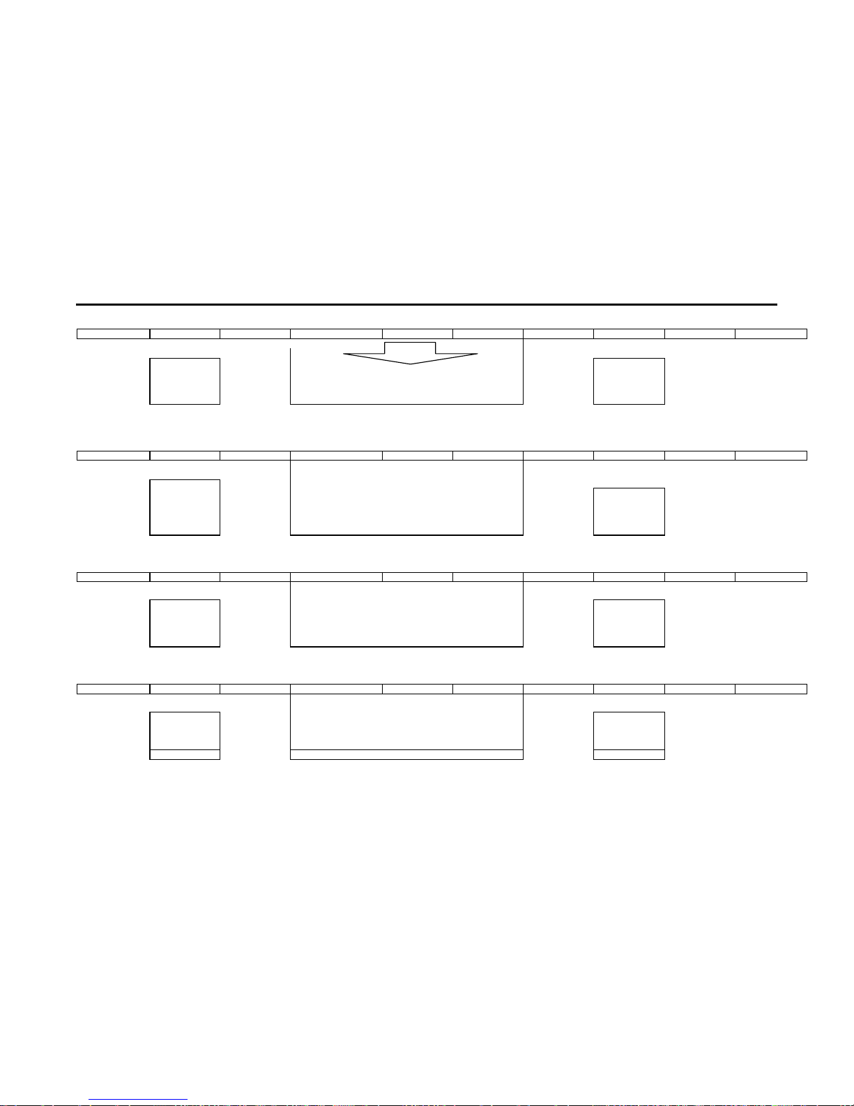
4-8 MICOM and Pins Voltage
4-8-1 Pin Layput
POWER
IR-IN
V-MUTE
3D-SDA
3D-SCL
3D-ENA
IDENT
MODE-SEL
PROTECT
1H-SYNC
SCL 2
SDA 2
CVBS
LOOP FILTER
ANALOG GND
SUB-AFT
KEY1
MAIN- AF T
KEY2
KEY3
ANALOG GND
HALF TONE
OSD B
ANALOG VCC
OSD G
OSD R
D2
POWER2
BUS-STO P
HOLD
SCL-3
SDA-3
TIMER-LED
S/W-MUTE
D1
AMP-M UTE
3D-RESET
N.C
XTAL GND
VCC
GND
XTAL2
XTAL1
/RESET
N.C
N.C
D3
SCL-1
SDA-1
VSYNC
HSYNC
BLANK
1
2
3
4
5
6
7
8
9
10
11
12
13
14
15
16
17
18
19
20
21
22
23
24
25
26
52
51
50
49
48
47
46
45
44
43
42
41
40
39
38
37
36
35
34
33
32
31
30
29
28
27
Z
9
0
3
7
1
1
2
P
S
C
Page 59

Alignment and Adjustments
4-24 Samsung Electronics
4-8-2 Micom Pins
1 POWER POWER ON/OFF RELAY CONTROL H--> L
2 IR IN REMOCON INPUT 5V
3 V-MUTE VIDEO SIGNAL MUTE 3V
4 3D-SDA 3D PHONIC DATA LINE 5V
5 3D-SCL 3D PHONIC CLOCK LINE 5V
6 3D-ENA 3D PHONIC ENABLE LINE 5V
7 IDENT VALID DTV SIGNAL (LOW) 5V
8 MODE-SEL MODE SELECTOR CONTROL 9 PROTECT PROTECT PORT 10 1H-SYNC NORMAL H,V-SYNC 3.5V
11 SCL 2 CLOCK BUS LINE 4.5V
12 SDA 2 DATA BUS LINE 4.5V
13 CVBS CVBS 1.7V
14 LOOP FILTER LOOP FILTER 1.9V
15 ANALOG GND GND GND
16 SUB-AFT SUB AUTO FINE TURNING CONTROL 2.64V
17 KEY 1 KEY SCAN 1 4.84V
18 MAIN-AFT MAIN TUNER AFT 1.9V
19 KEY 2 KEY SCAN 2 20 KEY 3 KEY SCAN 3 21 ANALOG GND GND 22 ANALOG VCC VCC 5V
23 HALF TONE SIGNAL FOR OSC-FREQUENCY OSD CONTROL 24 OSD B ON SCREEN DISPLAY BLUE OUTPUT 25 OSD G ON SCREEN DISPLAY GREEN OUTPUT 26 OSD R ON SCREEN DISPLAY RED OUTPUT -
PIN NO. ITEM FUNCTION OUT VOLT
Page 60

Alignment and Adjustments
Samsung Electronics 4-25
27 BLANK BLAKING SIGNAL OUTPUT 28 HSYNC HORIZONTAL SYNC INPUT 29 VSYNC VERTICAL SYNC INPUT 30 SDA-1 DATA BUS LINE 4.5V
31 SCL-1 CLOCK BUS LINE 4.12V
32 D3 CONVERGENCE D3 33 N.C N.C 34 N.C N.C 35 /RESET RESET 4.74V
36 XTAL1 XTAL 1 1.72V
37 XTAL2 XTAL 2 2.2V
38 GND GND 39 VCC VCC 5V
40 XTAL GND GND 41 N.C N.C 42 3D-RESET 3D PHONIC RESET 5V
43 AMP-MUTE MAIN AMP MUTE 44 D1 CONVERGENCE D1 45 S/W-MUTE SWITCH MUTE (NOT USED) 46 TIMER-LED TIMER LED 4.7V
47 SDA-3 DATA BUS LINE 4.6V
48 SCL-3 CLOCK BUS LINE 4.6V
49 HOLD HOLD 4.65V
50 BUS-STOP I
2
C BUS STOP 5V
51 POWER2 PC POWER CONTROL 4.65V
52 D2 CONVERGENCE D2 -
PIN NO. ITEM FUNCTION OUT VOLT
Page 61

Alignment and Adjustments
4-26 Samsung Electronics
4-8-3 PROSCAN MDL
1 DVD-Y DVD-Y INPUT 2.04V
2 GND GND GND
3 CVBS/Y CVBS/Y INPUT 1.76V
4 CIN C-INPUT 2.92V
5 GND GND GND
6 E-Pr/R E-Pr/R INPUT 2.0V
7 E-Y/G E-Y/G INPUT 2.0V
8 E-Pb/B E-Pb/B INPUT 2.0V
9 E-FB FAST BLANKING INPUT 0.25V
10 GND GND GND
11 HS1 1H-SYNC OUT 12 VS1 VS1 OUT 13 GND GND GND
14 SDA-2 SERIAL DATA LINE 2 4.7V
15 SCL-2 SERIAL CLOCK LINE 2 4.8V
16 5V 5V 5V
17 HD H-DRIVE OUT 1.6V
18 H-BLK H-BLANK INPUT 19 VD+ VERTICAL DRIVE (+VOLTAGE) 2.90V
20 VD- VERTICAL DRIVE (-VOLTAGE) 2.95V
21 ABL ABL INPUT 2.15V
22 V-BLK V-BLANKING 23 EW EAST WEST OUT 2.2V
24 N.C N.C 25 GND GND GND
26 V-OUT V-OUT N.C
27 H-OUT H-OUT N.C
28 HC 5V INPUT 29 GND GND GND
30 TEST-Y WHEN CG ADJ PATTERN INPUT -
PIN NO. ITEM FUNCTION OUT VOLT
Page 62

Alignment and Adjustments
Samsung Electronics 4-27
31 PC-R N.C 32 PC-G N.C 33 PC-B N.C 34 PC-H N.C 35 PC-V N.C 36 GND GND GND
37 OSD-R OSD-R INPUT 38 OSD-G OSD-G INPUT 39 OSD-B OSD-B INPUT 40 YS BLANK(MICOM OUT) 41 YM HALF TONE INPUT 42 V-MUTE VIDEO MUTE (V-CHIP ON) 4.72V
43 GND GND GND
44 9V 9V 9V
45 D-Pr D-Pr INPUT 46 D-Y D-Y INPUT 47 D-Pb D-Pb INPUT 48 PIP-F/B N.C 49 GND GND GND
50 R-OUT R-OUT 51 G-OUT G-OUT 52 B-OUT B-OUT 53 GND GND GND
54 IK IK OUT 3.65V
55 SPOT SPOT OUT 56 GND GND GND
57 VM-Y VM-Y OUT 5.42V
58 VM-MUTE N.C -
PIN NO. ITEM FUNCTION OUT VOLT
Page 63

Alignment and Adjustments
4-28 Samsung Electronics
4-8-4 PIP MODULE
1 GND GND GND
2 TV SUB-V INPUT 2.93V
3 GND GND GND
4 N.C N.C 5 8V 8V INPUT 8V
6 N.C N.C 7 PIP-Pr/R PIP-Pr/R (DVD SIG) OUT 2.02V
8 PIP-Y/G PIP-Y/G (DVD SIG) OUT 2.04V
9 PIP-Pb/B PIP-Pb/B (DVD SIG) OUT 2.02V
10 PIP-FB PIP FAST BLANKING 2.02V
11 12V 12V INPUT 12V
12 PIP-F/B N.C N.C
13 PIP-B DVD-B IN 14 PIP-G DVD-G IN 15 PIP-R DVD-R IN 16 N.C N.C 17 V-SYNC V-SYNC INPUT 18 H-SYNC H-SYNC INPUT 19 SCL SERIAL CLOCK LINE 4.11V
20 SDA SERIAL DATA LINE 4.5V
21 5V 5V INPUT 5V
22 GND GND GND
PIN NO. ITEM FUNCTION OUT VOLT
Page 64

Alignment and Adjustments
Samsung Electronics 4-29
4-8-5 3D/COMB MODULE
1 VIDEO MAIN VIDEO INPUT 2.74V
2 GND GND GND
3 9V 9V INPUT 9V
4 GND GND GND
5 SCL SERIAL CLOCK LINE 4.1V
6 SDA SERIAL DATA LINE 4.1V
7 V-3D COPY GUARD REJECT SIGNAL 3.8V
8 5V 5V INPUT 5V
9 Y-OUT MAIN Y OUT 10 GND GND GND
11 C-OUT MAIN C OUT 12 GND GND GND
1 SIF SIF OUT 3.25V
2 9V 9V INPUT 9V
3 GND GND GND
4 IF IF INPUT 4.5V
5 GND GND GND
6 AGC RF AGC IN 5.37V
7 TV-VIDEO TV-VIDEO OUT 8 AFT MAIN AFT INPUT 2V
9 GND GND GND
PIN NO. ITEM FUNCTION OUT VOLT
PIN NO. ITEM FUNCTION OUT VOLT
4-8-6 IF MODULE
Page 65

Alignment and Adjustments
4-30 Samsung Electronics
4-8-7 F/CONVERTER MODULE
1 5V 5V INPUT 5V
2 GND GND GND
3 R-IN PC R INPUT 4 G-IN PC G INPUT 5 B-IN PC B INPUT 6 GND GND GND
7 HS PC H-SYNC INPUT 8 VS PC V-SYNC INPUT 9 GND GND GND
10 SDA SERIAL DATA LINE 11 SCL SERIAL CLOCK LINE 12 GND GND GND
13 IR INPUT REMOCON 2.5V
14 GND GND GND
15 R-OUT/Y3 PC Y3 OUT 16 N.C N.C 17 B-OUT/C3 PC C3 OUT -
PIN NO. ITEM FUNCTION OUT VOLT
Page 66

Alignment and Adjustments
Samsung Electronics 4-31
4-8-8 3D-PHONIC MODULE
1 L-OUT SOUND L-OUT 4.5V
2 AGND GND GND
3 R-OUT SOUND R-OUT 4.5V
4 A-GND GND GND
5 C-OUT SOUND CENTER OUT 6 A-GND GND GND
7 S-OUT SURROUND OUT 0.83V
8 A-GND GND GND
9 12V 12V INPUT 12V
10 ENABLE 3D-ENABLE 5V
11 RESET 3D-RESET 5V
12 SDA SERIAL DATA LINE 4.96V
13 SCL SERIAL CLOCK LINE 4.96V
14 5V 5V INPUT 5V
15 L-IN 3D L-INPUT 3.86V
16 GND GND GND
17 R-IN 3D R-INPUT 3.22V
1 TV-R TV R-SOUND OUT 2 TV-L TV L-SOUND OUT 3 SCL SERIAL CLOCK LINE 4 SDA SERIAL DATA LINE 5 N.C N.C 6 GND GND GND
7 SIF SIF INPUT 8 N.C N.C 9 N.C N.C 10 9V 9V INPUT 9V
PIN NO. ITEM FUNCTION OUT VOLT
PIN NO. ITEM FUNCTION OUT VOLT
4-8-9 MTS MODULE
Page 67

Alignment and Adjustments
4-32 Samsung Electronics
4-8-10 H/V MODULE
1 12V 12V INPUT 12V
2 GND GND GND
3 HD H-DRIVE INPUT 1.6V
4 V-BLK V-BLANK INPUT 0.72V
5 2H-BLK 2H-BLANK OUT 0.54V
6 GND GND GND
7 PROTECT PROTECT ACTIV H
8 FBT-DC FBT DC FEED BACK 4.87V
9 X-RAY X-RAY PROTECT F/B 2.10V
10 N.C N.C 11 HV-REG HV-REG 3.54V
12 HV-DRIVE HIGH VOLTAGE DRIVE 0.32V
13 H-DRIVE H-DRIVE OUT 25V
14 GND GND GND
15 HEATER HEATER INPUT AC[0.7V]
16 N.C N.C 17 208V 208V INPUT 208V
18 N.C N.C 19 GND GND GND
20 V2 V2 INPUT
21 N.C N.C 22 N.C N.C 23 D-FOCUS DYNAMIC FOCUS OUT 24 N.C N.C 25 N.C N.C 26 SCREEN SCREEN INPUT 1356V
PIN NO. ITEM FUNCTION OUT VOLT
Page 68

Alignment and Adjustments
Samsung Electronics 4-33
4-8-11 CONV- MODULE
1 SDA D2 2 SCL D1 3 GND GND GND
4 BV BLUE VERTICAL OUT 5 BH BLUE HORIZONTAL OUT 6 GV GREEN VERTICAL OUT 7 GH GREEN HORIZONTAL OUT 8 RV RED VERTICAL OUT 9 RH RED HORIZONTAL OUT 10 -5.4V -5.4V INPUT -5.4V
11 5.4V 5.4V INPUT +5.4V
12 V-BLK V-BLK INPUT 13 GND GND GND
14 H-BLK H-BLK INPUT 0.52V
15 COMP COMP VIDEO OUTPUT (N.C) N.C
16 IR INPUT REMOCON 3V
17 CTRL CTRL (N.C) N.C
18 D3/SEL D3 0.2V
19 B WHEN TEST PATTERN B OUT 20 G(TEST) WHEN TEST PATTERN G OUT 21 R WHEN TEST PATTERN R OUT 22 SYNC SYNC OUTPUT 4.41V
PIN NO. ITEM FUNCTION OUT VOLT
Page 69

MEMO
4-34 Samsung Electronics
Page 70

Troubleshooting
Samsung Electronics 5-1
5. Troubleshooting
5-1 Convergence Misaligned
Normal
Abnormal
Abnormal
Check the
output voltage and waveform
of CN802, CN203 on
the Convergence Board
Check HZ01 out pin
(BV, BH, RV, RH, GV, GH)
Check the associated
circuitry
Check Convergence
Module
1. Check F802, F855,
F805, F806 on
the SUB Board
2. Check the output
from H-BLK, V-BLK,
D1, D2, D3 on
the Main Board
Normal
Page 71

5-2 No Sound
Troubleshooting
5-2 Samsung Electronics
Abnormal
Normal
Check IC665 input pin 3
Check Speaker
Normal
Check IC665
output pins 2,4
Check if CN601 is inserted
Check IC665
mute pin 5
Abnormal
Check F854 on
the SUB Board
Normal
Check IC665
output pins 7,11
Abnormal
Check the mute circuit
Normal
Check IC601
input pins 35, 38
Check IC665
Abnormal
Check H006
input pins 15,17
Normal
Check the 3D Phonic
circuit
Abnormal
Check ICV01
Input pins 49,51
Normal
Check ICV01
Abnormal
Abnormal
Insert CN601
(Connector)
Abnormal
Check H003
out Pins 1,2
Normal
Normal
Check Tone Control
Page 72

Troubleshooting
Samsung Electronics 5-3
5-3 No Raster (Sound OK)
Normal
Normal
Check High Voltage
Check IC501, 531,561
Normal
Check Heater
Check CN501
pins 1,3,5
Abnormal
Check CN501
(Connector)
Normal
Check CN501
(Connector)
Normal
Check H007
Normal
Check H007
input pins 3,4
Check ICV01
Abnormal
Check ICV01 input
pin 48
Normal
Check H009
Abnormal
Check H009
input pin 1
Normal
Check ICV01
Abnormal
Abnormal
Abnormal
Check H004
Check CRT PCB pin 1
Normal
Check ICV01
input pin 50
Abnormal
Normal
Check CN402 input
pin 12 (HV-DRIVER)
Check H401 CN402
HV-REG
Normal
Check H401
(OUT BLOCK)
Abnormal
Check H401,
IC471
Abnormal
Abnormal
Check H401 R437A
Check H401
Page 73

MEMO
5-4 Samsung Electronics
Page 74

6. Exploded View & Parts List
6-1 HCJ652W
Exploded View & Parts List
Samsung Electronics 6-1
CODE NO DESCRIPTION SPECIFICATION Q’TY
AA91-00168C ASSY-CABINET,MASK ;-,HB,BLK,DG902P+BK901P 1
AA91-00270A ASSY-DECORATION,JERSEY ;-,WOOD,SP200 JERS 1
AA91-10404A ASSY-CABINET,BOT ;-,SPT555JHD,JERSEY,V0,B 1
AA64-80052A LEG-FRONT ;-,SPT555JHD,DG703P,HIPS,HB,BLK 1
AA63-30225A COVER-WOOD ;-,SPT-555JHD,-,WOOD,-,-,-,- 2
AA95-00364A ASSY-DOOR ;-,PCJ652W/552W,P51A,-,-,- 1
3001-001062 SPEAKER ;15W,8ohm,94dB,45Hz 2
3001-000153 SPEAKER ;20W,8ohm,93dB,1.3KHz 2
AA59-40003P MODULE-FOCUS,PACK ;-,F300,NTSC,43,64x62, 1
3001-001045 SPEAKER ;15W,8ohm,91dB,65Hz 1
AA91-00176A ASSY-CABINET,WOOD ;-,WOOD,-,HCJ652W 1
AA67-00021A SUN-SCREEN ;-,65”W,H/C,A/S,PMMA,TRAN=82% 1
AA67-00009A SCREEN-TINT ;-,65W,DNP,P=0.72,TINT=10%,3. 1
AA61-00186F HOLDER-SCREEN,18T ;-,655H,ABS,HB,BLK,L740 1
AA67-00052A MIRROR-FRONT ;65W,GLASS,T3.0,FSM,-,1210* 1
AA63-00242A COVER-DUST ;-,65W2DR,-,WOOD,-,BLK,-,- 1
AA63-00109A COVER-MIRROR ;-,HCJ655W,-,WOOD,-,BLK,-,- 1
AA63-00236A COVER-BACK,TOP ;-,65W2DR,-,WOOD,-,BLK,-,- 1
AA64-00623A CABINET-BACK,BOARD ;-,652W,HARDBOARD,HIPS 1
AA95-00157E ASSY-PCB,CONVERGENCE ;-,HCJ652W,SVP-65W2D 1
AA95-00325A ASSY-PCB,SUB ;-,HCJ652WX/XAA,P51A,-,-,USA 1
AA94-01247B ASSY-PCB,MAIN(OPT) ;HCJ652WX/XAA,P51A,USA 1
AA95-00305B ASSY-PCB,TERMINAL ;-,PCJ552WX/XAA,P51A,-, 1
AA63-00045B TERMINAL-BOARD,ANT ;-,HIPS,-,PCJ533R,- 1
AA61-00051B HOLDER-CHASSIS ;-,PCJ533R,ABS,VO,GRAY,E-2 1
AA60-00042A SPACER-COVER,DUST ;FELT,T0.5,BLK,-,62W2DR 1
AA94-01726A ASSY-CRT(R) ;P16LFT00RFA,+380MG,9,BARE,H 1
AA94-01727A ASSY-CRT(B) ;P16LFT00HLA,+380MG,9,BARE,H 1
AA94-01728A ASSY-CRT(G) ;P16LFT00EMB,+380MG,9,BARE,H 1
AA61-00087B BRACKET-MAIN,M ;-,-,SECC,T1.6,-,-,- 2
AA61-00104B BRACKET-MAIN,S ;-,555J,SECC,T1.6,-,9 CRT 2
AA95-00357A ASSY-PCB,PRE AMP ;-,HCJ552WX/XAA,P51A,-,- 1
No.
1
2
3
4
5
6
7
8
9
10
11
12
13
14
15
16
17
18
19
20
21
22
23
24
25
26
27
28
29
30
31
32
Page 75

7. Electrical Parts List
Electrical Parts List
Samsung Electronics 7-1
ASSY-PCB,MAIN(OPT)
* AA94-01247BASSY-PCB,MAIN(OPT);HCJ652WX/XAA,P51A,USA
C101 2201-000144 C-CERAMIC,DISC;0.1nF,5%,50V,NP0,TP,8.5x3
C102 2201-000144 C-CERAMIC,DISC;0.1nF,5%,50V,NP0,TP,8.5x3
C103 2201-000119 C-CERAMIC,DISC;100nF,+80-20%,50V,Y5V,TP,
C104 2401-001363 C-AL;470uF,20%,16V,GP,TP,10x12.5,5
C105 2401-002619 C-AL;47uF,20%,25V,GP,TP,5x11,5
C106 2201-000144 C-CERAMIC,DISC;0.1nF,5%,50V,NP0,TP,8.5x3
C107 2305-000665 C-FILM,MPEF;100nF,5%,63V,TP,7.5x4.0x5.0m
C108 2201-000144 C-CERAMIC,DISC;0.1nF,5%,50V,NP0,TP,8.5x3
C109 2201-000119 C-CERAMIC,DISC;100nF,+80-20%,50V,Y5V,TP,
C110 2401-001363 C-AL;470uF,20%,16V,GP,TP,10x12.5,5
C112 2201-000144 C-CERAMIC,DISC;0.1nF,5%,50V,NP0,TP,8.5x3
C113 2401-002009 C-AL;100uF,20%,16V,GP,TP,6.3x7,5
C114 2201-000119 C-CERAMIC,DISC;100nF,+80-20%,50V,Y5V,TP,
C116 2401-000603 C-AL;1uF,20%,50V,GP,TP,5x11,5
C117 2301-000310 C-FILM,PEF;68nF,5%,50V,TP,8.0X8.5X4.0X5,
C118 2201-000180 C-CERAMIC,DISC;10nF,10%,50V,Y5V,TP,7x3,5
C119 2305-000665 C-FILM,MPEF;100nF,5%,63V,TP,7.5x4.0x5.0m
C121 2305-000665 C-FILM,MPEF;100nF,5%,63V,TP,7.5x4.0x5.0m
C125 2401-000603 C-AL;1uF,20%,50V,GP,TP,5x11,5
C126 2201-000119 C-CERAMIC,DISC;100nF,+80-20%,50V,Y5V,TP,
C129 2201-000144 C-CERAMIC,DISC;0.1nF,5%,50V,NP0,TP,8.5x3
C130 2201-000119 C-CERAMIC,DISC;100nF,+80-20%,50V,Y5V,TP,
C132 2305-000665 C-FILM,MPEF;100nF,5%,63V,TP,7.5x4.0x5.0m
C133 2401-001363 C-AL;470uF,20%,16V,GP,TP,10x12.5,5
C180 2401-000603 C-AL;1uF,20%,50V,GP,TP,5x11,5
C185 2401-001363 C-AL;470uF,20%,16V,GP,TP,10x12.5,5
C191 2401-002619 C-AL;47uF,20%,25V,GP,TP,5x11,5
C193 2201-000119 C-CERAMIC,DISC;100nF,+80-20%,50V,Y5V,TP,
C195 2401-002619 C-AL;47uF,20%,25V,GP,TP,5x11,5
C501 2305-000665 C-FILM,MPEF;100nF,5%,63V,TP,7.5x4.0x5.0m
C502 2401-001397 C-AL;470uF,20%,25V,GP,TP,10x16,5
C503 2305-000665 C-FILM,MPEF;100nF,5%,63V,TP,7.5x4.0x5.0m
C504 2401-000832 C-AL;220uF,20%,25V,GP,TP,8x11.5,5
C505 2305-000665 C-FILM,MPEF;100nF,5%,63V,TP,7.5x4.0x5.0m
C506 2401-002594 C-AL;220uF,20%,16V,GP,TP,8x11.5,5
C507 2305-000665 C-FILM,MPEF;100nF,5%,63V,TP,7.5x4.0x5.0m
C508 2401-002286 C-AL;470uF,20%,16V,WT,TP,10x12.5,5
C509 2305-000665 C-FILM,MPEF;100nF,5%,63V,TP,7.5x4.0x5.0m
C510 2401-000133 C-AL;1000uF,20%,16V,GP,TP,10x20,5
C511 2305-000665 C-FILM,MPEF;100nF,5%,63V,TP,7.5x4.0x5.0m
C512 2401-000689 C-AL;2200uF,20%,16V,GP,TP,13x25,5
C513 2401-002594 C-AL;220uF,20%,16V,GP,TP,8x11.5,5
C514 2305-000665 C-FILM,MPEF;100nF,5%,63V,TP,7.5x4.0x5.0m
C515 2201-000573 C-CERAMIC,DISC;0.047nF,5%,50V,NP0,TP,5x3
C516 2201-000573 C-CERAMIC,DISC;0.047nF,5%,50V,NP0,TP,5x3
C517 2401-002594 C-AL;220uF,20%,16V,GP,TP,8x11.5,5
C518 2305-000665 C-FILM,MPEF;100nF,5%,63V,TP,7.5x4.0x5.0m
C519 2305-000665 C-FILM,MPEF;100nF,5%,63V,TP,7.5x4.0x5.0m
C520 2401-002594 C-AL;220uF,20%,16V,GP,TP,8x11.5,5
C521 2305-000665 C-FILM,MPEF;100nF,5%,63V,TP,7.5x4.0x5.0m
C522 2401-002286 C-AL;470uF,20%,16V,WT,TP,10x12.5,5
C534 2401-002594 C-AL;220uF,20%,16V,GP,TP,8x11.5,5
C535 2305-000665 C-FILM,MPEF;100nF,5%,63V,TP,7.5x4.0x5.0m
C537 2305-000665 C-FILM,MPEF;100nF,5%,63V,TP,7.5x4.0x5.0m
C538 2401-001840 C-AL;100uF,20%,16V,GP,TP,6.3x11,5
C539 2401-001840 C-AL;100uF,20%,16V,GP,TP,6.3x11,5
C540 2305-000665 C-FILM,MPEF;100nF,5%,63V,TP,7.5x4.0x5.0m
C543 2201-000144 C-CERAMIC,DISC;0.1nF,5%,50V,NP0,TP,8.5x3
C544 2401-002144 C-AL;47uF,20%,16V,GP,TP,5x11,5
C545 2201-000573 C-CERAMIC,DISC;0.047nF,5%,50V,NP0,TP,5x3
C547 2201-000573 C-CERAMIC,DISC;0.047nF,5%,50V,NP0,TP,5x3
C548 2401-000471 C-AL;10uF,20%,50V,BP,TP,5x11,5mm
C549 2401-002594 C-AL;220uF,20%,16V,GP,TP,8x11.5,5
C550 2201-000119 C-CERAMIC,DISC;100nF,+80-20%,50V,Y5V,TP,
C551 2401-000360 C-AL;100uF,20%,50V,GP,TP,8x11.5,5
C552 2201-000119 C-CERAMIC,DISC;100nF,+80-20%,50V,Y5V,TP,
C639 2401-002009 C-AL;100uF,20%,16V,GP,TP,6.3x7,5
C640 2201-000119 C-CERAMIC,DISC;100nF,+80-20%,50V,Y5V,TP,
C664 2401-001068 C-AL;3300uF,20%,50V,GP,BK,22x40,10
C665 2401-000737 C-AL;2200uF,20%,50V,GP,TP,18x35.5,7.5
C666 2305-000665 C-FILM,MPEF;100nF,5%,63V,TP,7.5x4.0x5.0m
C667 2401-000603 C-AL;1uF,20%,50V,GP,TP,5x11,5
C668 2401-000603 C-AL;1uF,20%,50V,GP,TP,5x11,5
C669 2401-000962 C-AL;22uF,20%,50V,GP,TP,5x11,5
C670 2401-000603 C-AL;1uF,20%,50V,GP,TP,5x11,5
C671 2401-001537 C-AL;47uF,20%,25V,GP,TP,6.3x7mm,5mm
C672 2401-000360 C-AL;100uF,20%,50V,GP,TP,8x11.5,5
C676 2401-001192 C-AL;33uF,20%,50V,GP,TP,6.3x11,5
C686 2301-000192 C-FILM,PEF;1nF,5%,50V,TP,5.3x10mm,5mm
C687 2301-000192 C-FILM,PEF;1nF,5%,50V,TP,5.3x10mm,5mm
C688 2401-000192 C-AL;1000uF,20%,50V,GP,TP,16x25,7.5
C689 2305-000665 C-FILM,MPEF;100nF,5%,63V,TP,7.5x4.0x5.0m
C690 2305-000665 C-FILM,MPEF;100nF,5%,63V,TP,7.5x4.0x5.0m
C691 2401-000192 C-AL;1000uF,20%,50V,GP,TP,16x25,7.5
C701 2401-000027 C-AL;4.7uF,20%,50V,GP,TP,5x11,5
C711 2305-000665 C-FILM,MPEF;100nF,5%,63V,TP,7.5x4.0x5.0m
C712 2201-000426 C-CERAMIC,DISC;0.027nF,5%,50V,SL,TP,5x3,
C713 2401-000471 C-AL;10uF,20%,50V,BP,TP,5x11,5mm
C714 2305-000665 C-FILM,MPEF;100nF,5%,63V,TP,7.5x4.0x5.0m
C715 2305-000665 C-FILM,MPEF;100nF,5%,63V,TP,7.5x4.0x5.0m
C801 2401-002300 C-AL;47uF,20%,50V,GP,TP,6.3x11,5
C901 2201-000292 C-CERAMIC,DISC;1nF,10%,50V,Y5P,TP,5x3.5,
C904 2202-002037 C-CERAMIC,MLC-AXIAL;100nF,80-20%,50V,Y5V
C905 2401-001496 C-AL;47uF,20%,16V,GP,TP,5x7,5
C906 2305-000149 C-FILM,MPEF;100nF,5%,100V,TP,12x12.5x6.5
C907 2301-000111 C-FILM,PEF;1.8nF,5%,50V,TP,6.5x3.0x5.5mm
C908 2201-000292 C-CERAMIC,DISC;1nF,10%,50V,Y5P,TP,5x3.5,
C909 2201-000292 C-CERAMIC,DISC;1nF,10%,50V,Y5P,TP,5x3.5,
C910 2201-000292 C-CERAMIC,DISC;1nF,10%,50V,Y5P,TP,5x3.5,
C911 2201-000119 C-CERAMIC,DISC;100nF,+80-20%,50V,Y5V,TP,
C912 2201-000119 C-CERAMIC,DISC;100nF,+80-20%,50V,Y5V,TP,
C913 2201-000193 C-CERAMIC,DISC;0.01nF,0.25pF,50V,NP0,TP,
C914 2201-000573 C-CERAMIC,DISC;0.047nF,5%,50V,NP0,TP,5x3
C915 2201-000119 C-CERAMIC,DISC;100nF,+80-20%,50V,Y5V,TP,
C916 2401-002042 C-AL;220uF,20%,10V,GP,TP,6.3x11,5
C917 2401-002144 C-AL;47uF,20%,16V,GP,TP,5x11,5
C918 2201-000119 C-CERAMIC,DISC;100nF,+80-20%,50V,Y5V,TP,
C919 2401-000480 C-AL;10uF,20%,50V,GP,TP,5x11,5
C920 2201-000119 C-CERAMIC,DISC;100nF,+80-20%,50V,Y5V,TP,
C921 2201-000119 C-CERAMIC,DISC;100nF,+80-20%,50V,Y5V,TP,
C922 2201-000119 C-CERAMIC,DISC;100nF,+80-20%,50V,Y5V,TP,
C925 2201-000119 C-CERAMIC,DISC;100nF,+80-20%,50V,Y5V,TP,
C926 2401-000480 C-AL;10uF,20%,50V,GP,TP,5x11,5
CLAMP2 AA65-30105B CLAMP-WIRE;NYLON 66,V2,NTR,25MM,ALL MODE
CMPW AA65-30105B CLAMP-WIRE;NYLON 66,V2,NTR,25MM,ALL MODE
CMPW AA65-30013ACLAMP-WIRE;NYLON-66,V0,NTR,DAWH-45N,-,CMPW AA65-30018ACLAMP-WIRE;NYLON-66,-,-,DATL-600,DONG-A,
CMPW AA65-30104B CLAMP-WIRE;NYLON 66,V2,BLK,W2 Z5,ALL MOD
CN003 3711-002642 CONNECTOR-HEADER;BOX,3P,1R,2.5MM,STRAIGH
CN201 3711-002647 CONNECTOR-HEADER;BOX,8P,1R,2.5mm,STRAIGH
CN202 3711-002641 CONNECTOR-HEADER;BOX,10P,1R,2.54mm,STRAI
CN501 3711-002647 CONNECTOR-HEADER;BOX,8P,1R,2.5mm,STRAIGH
CN601 3711-002643 CONNECTOR-HEADER;BOX,4P,1R,2.5MM,STRAIGH
CN602 3711-002644 CONNECTOR-HEADER;BOX,5P,1R,2.5mm,STRAIGH
CN801 3711-003641 CONNECTOR-HEADER;BOX,12P,1R,2.5mm,STRAIG
CNT01 3710-001208 CONNECTOR-SOCKET;32P,2R,2.54mm,STRAIGHT,
CNT02 3710-001208 CONNECTOR-SOCKET;32P,2R,2.54mm,STRAIGHT,
CNY01 3711-000628 CONNECTOR-HEADER;-,11P,1R,2.5mm,STRAIGHT
CORE 3301-001201 CORE-FERRITE;AE,230.5x10.25x36mm,1500,28
CORE2 3301-001201 CORE-FERRITE;AE,230.5x10.25x36mm,1500,28
CP06 2301-000192 C-FILM,PEF;1nF,5%,50V,TP,5.3x10mm,5mm
CP07 2301-000383 C-FILM,PEF;10nF,5%,50V,TP,6x7x3.2mm,5mm
Loc. No. Code No. Description ; Specification Remark Loc. No. Code No. Description ; Specification Remark
7-1 HCJ652WX/XAA
Page 76

CP10 2401-000404 C-AL;10uF,20%,16V,BP,TP,5x11,5
CS801 2201-000332 C-CERAMIC,DISC;2.2nF,20%,250V,Y5U,TP,9x4
CS802 2201-000332 C-CERAMIC,DISC;2.2nF,20%,250V,Y5U,TP,9x4
CS803 2401-003370 C-AL;47uF,20%,450V,GP,BK,16X35.5,7.
CS804 2201-000119 C-CERAMIC,DISC;100nF,+80-20%,50V,Y5V,TP,
CS805 2401-001101 C-AL;330uF,20%,16V,GP,TP,8x11.5,5
CS807 2201-000119 C-CERAMIC,DISC;100nF,+80-20%,50V,Y5V,TP,
CS808 2401-001363 C-AL;470uF,20%,16V,GP,TP,10x12.5,5
CS809 2201-000556 C-CERAMIC,DISC;0.47nF,10%,500V,Y5P,TP,5.
CS810 2201-000446 C-CERAMIC,DISC;3.3nF,20%,400V,Y5U,TP,15x
CS811 2201-000446 C-CERAMIC,DISC;3.3nF,20%,400V,Y5U,TP,15x
CS812 2201-002076 C-CERAMIC,DISC;0.068nF,5%,1kV,SL,TP,8x4m
D501 0401-000005 DIODE-SWITCHING;1N4148,100V,200MA,DO-35,
D664 0402-000546 DIODE-RECTIFIER;TVR10G,400V,1.0A,DO-41,T
D665 0401-000005 DIODE-SWITCHING;1N4148,100V,200MA,DO-35,
D666 0401-000005 DIODE-SWITCHING;1N4148,100V,200MA,DO-35,
D667 0401-000005 DIODE-SWITCHING;1N4148,100V,200MA,DO-35,
D668 0401-000005 DIODE-SWITCHING;1N4148,100V,200MA,DO-35,
D669 0401-000005 DIODE-SWITCHING;1N4148,100V,200MA,DO-35,
D671 0402-000132 DIODE-RECTIFIER;1N4004,400V,1A,DO-41,TP
D672 0402-000132 DIODE-RECTIFIER;1N4004,400V,1A,DO-41,TP
D701 0401-000005 DIODE-SWITCHING;1N4148,100V,200MA,DO-35,
D702 0401-000005 DIODE-SWITCHING;1N4148,100V,200MA,DO-35,
D703 0401-000005 DIODE-SWITCHING;1N4148,100V,200MA,DO-35,
D901 0401-000005 DIODE-SWITCHING;1N4148,100V,200MA,DO-35,
D902 0401-000005 DIODE-SWITCHING;1N4148,100V,200MA,DO-35,
D903 0401-000005 DIODE-SWITCHING;1N4148,100V,200MA,DO-35,
D904 0401-000005 DIODE-SWITCHING;1N4148,100V,200MA,DO-35,
D905 0401-000005 DIODE-SWITCHING;1N4148,100V,200MA,DO-35,
DS801 0402-000102 DIODE-BRIDGE;D2SB60,600V,1.5A,DS802 1405-000152 VARISTOR;560V,2500A,14x8.5mm,TP
DS803 0403-000300 DIODE-ZENER;MTZ8.2B,8.2V,7.78-8.19V,500m
DS804 0403-000294 DIODE-ZENER;MTZ4.7B,4.7V,4.55-4.80V,500m
DS805 0402-000534 DIODE-RECTIFIER;RG10V,400V,1.2A,DO-201,T
DS806 1405-001030 VARISTOR;120V,2500A,14x8.5mm,TP
DS807 0402-000546 DIODE-RECTIFIER;TVR10G,400V,1.0A,DO-41,T
DS808 1405-000152 VARISTOR;560V,2500A,14x8.5mm,TP
DS809 0404-001056 DIODE-SCHOTTKY;RK16,60V,1.5A,DO-204AC,TP
DS810 1405-000152 VARISTOR;560V,2500A,14x8.5mm,TP
DZ503 0403-000563 DIODE-ZENER;MTZ9.1B,9.1V,8.57-9.01V,500m
DZ504 0403-000563 DIODE-ZENER;MTZ9.1B,9.1V,8.57-9.01V,500m
DZ505 0403-000563 DIODE-ZENER;MTZ9.1B,9.1V,8.57-9.01V,500m
DZ506 0403-000296 DIODE-ZENER;MTZ5.6B,5.6V,5.45-5.73V,500m
DZ507 0403-000297 DIODE-ZENER;MTZ6.2B,6.2V,5.96-6.27V,500m
DZ508 0403-000297 DIODE-ZENER;MTZ6.2B,6.2V,5.96-6.27V,500m
DZ510 0403-000297 DIODE-ZENER;MTZ6.2B,6.2V,5.96-6.27V,500m
DZ511 0403-000297 DIODE-ZENER;MTZ6.2B,6.2V,5.96-6.27V,500m
DZ512 0403-000297 DIODE-ZENER;MTZ6.2B,6.2V,5.96-6.27V,500m
DZ513 0403-000289 DIODE-ZENER;MTZ10C,10V,9.7-10.2V,500mW,D
DZ665 0403-001039 DIODE-ZENER;MA2560,56V,52-60V,1W,DO-41,T
DZ666 0403-000656 DIODE-ZENER;MTZ15C,15V,14.35-15.09V,500m
DZ667 0403-000355 DIODE-ZENER;UZ5.1BSB,5.1V,4.97-5.18V,500
DZ701 0403-000289 DIODE-ZENER;MTZ10C,10V,9.7-10.2V,500mW,D
DZ801 0403-000700 DIODE-ZENER;TZP33A,33V,31-35V,1W,DO-41,T
DZ903 0403-000297 DIODE-ZENER;MTZ6.2B,6.2V,5.96-6.27V,500m
DZ904 0403-000297 DIODE-ZENER;MTZ6.2B,6.2V,5.96-6.27V,500m
DZ905 0403-000297 DIODE-ZENER;MTZ6.2B,6.2V,5.96-6.27V,500m
DZ911 0403-000296 DIODE-ZENER;MTZ5.6B,5.6V,5.45-5.73V,500m
DZ912 0403-000296 DIODE-ZENER;MTZ5.6B,5.6V,5.45-5.73V,500m
DZ913 0403-000296 DIODE-ZENER;MTZ5.6B,5.6V,5.45-5.73V,500m
DZ916 0403-000297 DIODE-ZENER;MTZ6.2B,6.2V,5.96-6.27V,500m
DZ917 0403-000297 DIODE-ZENER;MTZ6.2B,6.2V,5.96-6.27V,500m
DZ918 0403-000297 DIODE-ZENER;MTZ6.2B,6.2V,5.96-6.27V,500m
F101 2903-000135 FILTER-CERAMIC;BP,4.5MHz,+-60KHz,6dB,-,T
F102 2903-000129 FILTER-CERAMIC;TR,4.5M/4.72MHZ,-,-,-,TP,
F901 3301-000287 CORE-FERRITE BEAD;AA,3.5x1.0x6.0mm,1500,
FCSM AA59-40003P MODULE-FOCUS,PACK;-,F300,NTSC,43,64x62,
H001 AA40-10005RTUNER-F/S,LNA;TECC1070PG30A(S),NTSC/USA,
H002 AA40-10005UTUNER-F/S;TCPN9082PC27A(S),NTSC/USA,TR,1
H003 AA59-40003QMODULE-MTS;-,MZ-201,ZENITH,US,43X54,H004 AA59-00028AMODULE-IF;-,SP-222,NTSC,USA,74X54,IC101 1204-001435 IC-IF SYSTEM;LA7565B,DIP,24P,300MIL,PLAS
IC101 1204-001204 IC-DECODER;TDA9850,DIP,32P,4000MIL,PLAST
IC101 1203-000577 IC-VOLTAGE REGUATOR;3090,ZIP,5P,-,PLASTI H/SINK
IC102 1203-000203 IC-POSI.ADJUST REG.;3050,TO-220,5P,-,PLA H/SINK
IC501 1203-000165 IC-POSI.ADJUST REG.;78R12,TO-220,3P,-,-, H/SINK
IC502 1203-000203 IC-POSI.ADJUST REG.;3050,TO-220,5P,-,PLA H/SINK
IC503 1203-000203 IC-POSI.ADJUST REG.;3050,TO-220,5P,-,PLA H/SINK
IC504 1203-000203 IC-POSI.ADJUST REG.;3050,TO-220,5P,-,PLA H/SINK
IC506 1203-000293 IC-POSI.FIXED REG.;7808,TO-220,3P,-,PLAS
IC507 1204-001510 IC-SEPARATOR;EL4583CN,DIP,16P,-,PLASTIC,
IC665 1201-001026 IC-POWER AMP;7265,ZIP,11P,19.6MIL,DUAL,1 H/SINK
IC807 1203-000274 IC-POSI.FIXED REG.;7805,TO-220,3P,-,PLAS H/SINK
IC901 AA13-00012AIC-MCU;Z9037112PSC-OTP,OTP,ST,64kword
IC902 1103-001105 IC-EEPROM;24C040,4Kx1BIT,DIP,8P,300MIL,1
IC903 1203-001274 IC-VOL. DETECTOR;7545,TO-92,3P,-,PLASTIC
IC904 1203-000515 IC-VOL. DETECTOR;7042,TO-92,3P,177MIL,PL
ICP02 0801-000284 IC-CMOS LOGIC;4528,MULTIVIBRATOR,DIP,16P
ICS801 AA13-00024AIC-HYBRID;-,TNY253P,-,8PIN,-,ICS802 0604-001032 PHOTO-COUPLER;TR,170-260%,300mW,DIP-4,ST
IF AA39-30007AIF-CABLE;-,T,100mm,1365#26
J137 2001-000281 R-CARBON;100OHM,5%,1/8W,AA,TP,1.8X3.2MM
J244 2701-000115 INDUCTOR-AXIAL;10uH,10%,3x7mm
L101 2701-001040 INDUCTOR-AXIAL;10uH,10%,4.5x14mm
L102 2701-000115 INDUCTOR-AXIAL;10uH,10%,3x7mm
L103 2701-000115 INDUCTOR-AXIAL;10uH,10%,3x7mm
L104 2701-000115 INDUCTOR-AXIAL;10uH,10%,3x7mm
L106 2701-001040 INDUCTOR-AXIAL;10uH,10%,4.5x14mm
L107 2701-000116 INDUCTOR-AXIAL;10uH,10%,4.2x9.8mm
L108 2701-000115 INDUCTOR-AXIAL;10uH,10%,3x7mm
L201 AA27-10001CCOIL-CHOKE;-,100uH,K,-,5.0A,ST,700UH-K(R
L501 3301-000287 CORE-FERRITE BEAD;AA,3.5x1.0x6.0mm,1500,
L502 2701-000116 INDUCTOR-AXIAL;10uH,10%,4.2x9.8mm
L503 3301-000287 CORE-FERRITE BEAD;AA,3.5x1.0x6.0mm,1500,
L504 3301-000287 CORE-FERRITE BEAD;AA,3.5x1.0x6.0mm,1500,
L505 3301-000287 CORE-FERRITE BEAD;AA,3.5x1.0x6.0mm,1500,
L506 3301-000287 CORE-FERRITE BEAD;AA,3.5x1.0x6.0mm,1500,
L507 3301-000287 CORE-FERRITE BEAD;AA,3.5x1.0x6.0mm,1500,
L509 2701-001040 INDUCTOR-AXIAL;10uH,10%,4.5x14mm
L510 3301-000287 CORE-FERRITE BEAD;AA,3.5x1.0x6.0mm,1500,
L511 3301-000287 CORE-FERRITE BEAD;AA,3.5x1.0x6.0mm,1500,
L512 3301-000287 CORE-FERRITE BEAD;AA,3.5x1.0x6.0mm,1500,
L513 3301-000287 CORE-FERRITE BEAD;AA,3.5x1.0x6.0mm,1500,
L514 3301-000287 CORE-FERRITE BEAD;AA,3.5x1.0x6.0mm,1500,
L516 2701-001040 INDUCTOR-AXIAL;10uH,10%,4.5x14mm
L517 2701-001007 INDUCTOR-AXIAL;24uH,10%,4.5x14mm
L601 AA29-00004AFILTER-LINE NOISE;-,20UH,3A,AC80-260V,TQ
L902 2701-000115 INDUCTOR-AXIAL;10uH,10%,3x7mm
L903 2701-001040 INDUCTOR-AXIAL;10uH,10%,4.5x14mm
L907 3301-000287 CORE-FERRITE BEAD;AA,3.5x1.0x6.0mm,1500,
L909 3301-000287 CORE-FERRITE BEAD;AA,3.5x1.0x6.0mm,1500,
L910 3301-000287 CORE-FERRITE BEAD;AA,3.5x1.0x6.0mm,1500,
L911 2901-000297 FILTER-EMI ON BOARD;-,3A,-,-,3.5x5,TP,L913 3301-000287 CORE-FERRITE BEAD;AA,3.5x1.0x6.0mm,1500,
LEAD AA39-00036BLEAD CONNECTOR-ASSY;-,3191-01R,35750-101
LEADC AA39-00025ALEAD CONNECTOR-ASSY;-,YFH800-02,YFH800-0
LEDC AA39-20577ALEAD CONNECTOR-ASSY;-,YFH806-06,-,6(3)P,
LS801 2901-000297 FILTER-EMI ON BOARD;-,3A,-,-,3.5x5,TP,LS802 2901-000297 FILTER-EMI ON BOARD;-,3A,-,-,3.5x5,TP,LS803 3301-000287 CORE-FERRITE BEAD;AA,3.5x1.0x6.0mm,1500,
PCB AA41-11053DPCB-MAIN;P51A,1L,FR-1,330x245x1.6T,1A,PCBM AA41-11040APCB-MTS MODULE;PLT51A,1L,FR-1,245x245x1.
Q501 0501-000389 TR-SMALL SIGNAL;KSC815,NPN,400mW,TO-92,T
Q502 0501-000389 TR-SMALL SIGNAL;KSC815,NPN,400mW,TO-92,T
Q503 0501-000389 TR-SMALL SIGNAL;KSC815,NPN,400mW,TO-92,T
Q504 0501-000389 TR-SMALL SIGNAL;KSC815,NPN,400mW,TO-92,T
Q665 0501-000389 TR-SMALL SIGNAL;KSC815,NPN,400mW,TO-92,T
Q666 0501-000389 TR-SMALL SIGNAL;KSC815,NPN,400mW,TO-92,T
Q667 0501-000389 TR-SMALL SIGNAL;KSC815,NPN,400mW,TO-92,T
Q701 0501-000389 TR-SMALL SIGNAL;KSC815,NPN,400mW,TO-92,T
Q702 0501-000389 TR-SMALL SIGNAL;KSC815,NPN,400mW,TO-92,T
Q703 0501-000389 TR-SMALL SIGNAL;KSC815,NPN,400mW,TO-92,T
Q901 0501-000389 TR-SMALL SIGNAL;KSC815,NPN,400mW,TO-92,T
Q902 0501-000389 TR-SMALL SIGNAL;KSC815,NPN,400mW,TO-92,T
Q903 0501-000389 TR-SMALL SIGNAL;KSC815,NPN,400mW,TO-92,T
Q909 0501-000283 TR-SMALL SIGNAL;KSA539,PNP,400mW,TO-92,T
Q910 0501-000389 TR-SMALL SIGNAL;KSC815,NPN,400mW,TO-92,T
QP03 0501-000389 TR-SMALL SIGNAL;KSC815,NPN,400mW,TO-92,T
QP04 0501-000389 TR-SMALL SIGNAL;KSC815,NPN,400mW,TO-92,T
QS801 0501-000369 TR-SMALL SIGNAL;KSC2331-Y,NPN,1W,TO-92L,
R121 2008-000266 R-FUSIBLE(S);1ohm,5%,2W,AF,TP,3.9x10mm
R123 2001-000429 R-CARBON;1KOHM,5%,1/8W,AA,TP,1.8X3.2MM
R125 2001-000281 R-CARBON;100OHM,5%,1/8W,AA,TP,1.8X3.2MM
R126 2001-000281 R-CARBON;100OHM,5%,1/8W,AA,TP,1.8X3.2MM
Electrical Parts List
7-2 Samsung Electronics
Loc. No. Code No. Description ; Specification Remark Loc. No. Code No. Description ; Specification Remark
Page 77

R128 2001-000281 R-CARBON;100OHM,5%,1/8W,AA,TP,1.8X3.2MM
R129 2001-000281 R-CARBON;100OHM,5%,1/8W,AA,TP,1.8X3.2MM
R130 2001-000281 R-CARBON;100OHM,5%,1/8W,AA,TP,1.8X3.2MM
R131 2001-000739 R-CARBON;4.7MOHM,5%,1/8W,AA,TP,1.8X3.2M
R132 2001-000739 R-CARBON;4.7MOHM,5%,1/8W,AA,TP,1.8X3.2M
R133 2001-000449 R-CARBON;2.2KOHM,5%,1/8W,AA,TP,1.8X3.2M
R134 2001-000734 R-CARBON;4.7KOHM,5%,1/8W,AA,TP,1.8X3.2M
R143 2001-000281 R-CARBON;100OHM,5%,1/8W,AA,TP,1.8X3.2MM
R144 2001-000281 R-CARBON;100OHM,5%,1/8W,AA,TP,1.8X3.2MM
R501 2001-000066 R-CARBON(S);10KOHM,5%,1/2W,AA,TP,2.4X6.4
R502 2001-000281 R-CARBON;100OHM,5%,1/8W,AA,TP,1.8X3.2MM
R503 2001-000281 R-CARBON;100OHM,5%,1/8W,AA,TP,1.8X3.2MM
R504 2001-000281 R-CARBON;100OHM,5%,1/8W,AA,TP,1.8X3.2MM
R505 2001-000281 R-CARBON;100OHM,5%,1/8W,AA,TP,1.8X3.2MM
R506 2001-000515 R-CARBON;220OHM,5%,1/8W,AA,TP,1.8X3.2MM
R507 2001-000515 R-CARBON;220OHM,5%,1/8W,AA,TP,1.8X3.2MM
R508 2001-000281 R-CARBON;100OHM,5%,1/8W,AA,TP,1.8X3.2MM
R509 2008-000266 R-FUSIBLE(S);1ohm,5%,2W,AF,TP,3.9x10mm
R510 2008-000266 R-FUSIBLE(S);1ohm,5%,2W,AF,TP,3.9x10mm
R511 2008-001088 R-FUSIBLE(S);1ohm,5%,2W,AG,TP,3.9x12mm
R512 2001-000003 R-CARBON;330ohm,5%,1/8W,AA,TP,1.8x3.2mm
R513 2001-000281 R-CARBON;100OHM,5%,1/8W,AA,TP,1.8X3.2MM
R515 2001-000429 R-CARBON;1KOHM,5%,1/8W,AA,TP,1.8X3.2MM
R516 2001-000429 R-CARBON;1KOHM,5%,1/8W,AA,TP,1.8X3.2MM
R517 2001-000290 R-CARBON;10KOHM,5%,1/8W,AA,TP,1.8X3.2MM
R518 2001-000786 R-CARBON;47KOHM,5%,1/8W,AA,TP,1.8X3.2MM
R524 2001-000739 R-CARBON;4.7MOHM,5%,1/8W,AA,TP,1.8X3.2M
R525 2001-000739 R-CARBON;4.7MOHM,5%,1/8W,AA,TP,1.8X3.2M
R526 2001-000739 R-CARBON;4.7MOHM,5%,1/8W,AA,TP,1.8X3.2M
R528 2001-000429 R-CARBON;1KOHM,5%,1/8W,AA,TP,1.8X3.2MM
R531 2001-000739 R-CARBON;4.7MOHM,5%,1/8W,AA,TP,1.8X3.2M
R532 2001-000037 R-CARBON(S);330OHM,5%,1/2W,AA,TP,2.4X6.4
R626 2001-000411 R-CARBON;18KOHM,5%,1/8W,AA,TP,1.8X3.2MM
R627 2001-000411 R-CARBON;18KOHM,5%,1/8W,AA,TP,1.8X3.2MM
R661 2004-001970 R-METAL;1.8Kohm,1%,1/2W,AA,TP,6.5x2.5m
R662 2004-001970 R-METAL;1.8Kohm,1%,1/2W,AA,TP,6.5x2.5m
R665 2001-000052 R-CARBON(S);3.3KOHM,5%,1/2W,AA,TP,2.4X6.
R666 2001-000052 R-CARBON(S);3.3KOHM,5%,1/2W,AA,TP,2.4X6.
R668 2001-000780 R-CARBON;470OHM,5%,1/8W,AA,TP,1.8X3.2MM
R669 2001-001144 R-CARBON(S);4.7KOHM,5%,1/2W,AA,TP,2.4X6.
R670 2001-000085 R-CARBON(S);100KOHM,5%,1/2W,AA,TP,2.4X6.
R671 2001-000066 R-CARBON(S);10KOHM,5%,1/2W,AA,TP,2.4X6.4
R672 2001-000066 R-CARBON(S);10KOHM,5%,1/2W,AA,TP,2.4X6.4
R673 2001-001086 R-CARBON(S);18KOHM,5%,1/2W,AA,TP,2.4X6.4
R673A 2001-001144 R-CARBON(S);4.7KOHM,5%,1/2W,AA,TP,2.4X6.
R674 2001-000780 R-CARBON;470OHM,5%,1/8W,AA,TP,1.8X3.2MM
R675 2001-000066 R-CARBON(S);10KOHM,5%,1/2W,AA,TP,2.4X6.4
R676 2001-000812 R-CARBON;5.6KOHM,5%,1/8W,AA,TP,1.8X3.2M
R677 2001-000290 R-CARBON;10KOHM,5%,1/8W,AA,TP,1.8X3.2MM
R678 2001-000008 R-CARBON;15KOHM,5%,1/8W,AA,TP,1.8X3.2MM
R679 2001-001071 R-CARBON(S);12KOHM,5%,1/2W,AA,TP,2.4X6.4
R680 2001-001000 R-CARBON;82KOHM,5%,1/8W,AA,TP,1.8X3.2MM
R681 2004-001970 R-METAL;1.8Kohm,1%,1/2W,AA,TP,6.5x2.5m
R682 2004-002019 R-METAL(S);33Kohm,1%,1/2W,AA,TP,2.5x6.5m
R683 2004-002019 R-METAL(S);33Kohm,1%,1/2W,AA,TP,2.5x6.5m
R684 2004-001970 R-METAL;1.8Kohm,1%,1/2W,AA,TP,6.5x2.5m
R685 2004-001390 R-METAL(S);1Kohm,2%,1/2W,AA,TP,2.4x6.4mm
R686 2004-001390 R-METAL(S);1Kohm,2%,1/2W,AA,TP,2.4x6.4mm
R687 2001-001146 R-CARBON(S);4.7OHM,5%,1/2W,AA,TP,2.4X6.4
R689 2001-001146 R-CARBON(S);4.7OHM,5%,1/2W,AA,TP,2.4X6.4
R701 2001-000786 R-CARBON;47KOHM,5%,1/8W,AA,TP,1.8X3.2MM
R702 2001-000290 R-CARBON;10KOHM,5%,1/8W,AA,TP,1.8X3.2MM
R703 2001-000290 R-CARBON;10KOHM,5%,1/8W,AA,TP,1.8X3.2MM
R704 2001-000290 R-CARBON;10KOHM,5%,1/8W,AA,TP,1.8X3.2MM
R711 2001-000734 R-CARBON;4.7KOHM,5%,1/8W,AA,TP,1.8X3.2M
R712 2001-000734 R-CARBON;4.7KOHM,5%,1/8W,AA,TP,1.8X3.2M
R713 2001-000522 R-CARBON;22KOHM,5%,1/8W,AA,TP,1.8X3.2MM
R714 2001-000633 R-CARBON;30KOHM,5%,1/8W,AA,TP,1.8X3.2MM
R715 2001-000429 R-CARBON;1KOHM,5%,1/8W,AA,TP,1.8X3.2MM
R716 2001-000290 R-CARBON;10KOHM,5%,1/8W,AA,TP,1.8X3.2MM
R717 2001-000508 R-CARBON;220KOHM,5%,1/8W,AA,TP,1.8X3.2M
R801 2003-002161 R-METAL OXIDE(S);22KOHM,5%,3W,AG,TP,6X16
R901 2001-000734 R-CARBON;4.7KOHM,5%,1/8W,AA,TP,1.8X3.2M
R903 2001-000429 R-CARBON;1KOHM,5%,1/8W,AA,TP,1.8X3.2MM
R904 2001-000290 R-CARBON;10KOHM,5%,1/8W,AA,TP,1.8X3.2MM
R905 2001-000734 R-CARBON;4.7KOHM,5%,1/8W,AA,TP,1.8X3.2M
R906 2001-000429 R-CARBON;1KOHM,5%,1/8W,AA,TP,1.8X3.2MM
R907 2001-000429 R-CARBON;1KOHM,5%,1/8W,AA,TP,1.8X3.2MM
R908 2001-000515 R-CARBON;220OHM,5%,1/8W,AA,TP,1.8X3.2MM
R909 2001-000515 R-CARBON;220OHM,5%,1/8W,AA,TP,1.8X3.2MM
R910 2001-000515 R-CARBON;220OHM,5%,1/8W,AA,TP,1.8X3.2MM
R912 2001-000003 R-CARBON;330ohm,5%,1/8W,AA,TP,1.8x3.2mm
R913 2001-000786 R-CARBON;47KOHM,5%,1/8W,AA,TP,1.8X3.2MM
R914 2001-000281 R-CARBON;100OHM,5%,1/8W,AA,TP,1.8X3.2MM
R915 2001-000281 R-CARBON;100OHM,5%,1/8W,AA,TP,1.8X3.2MM
R916 2001-000472 R-CARBON;2.7KOHM,5%,1/8W,AA,TP,1.8X3.2M
R917 2001-000472 R-CARBON;2.7KOHM,5%,1/8W,AA,TP,1.8X3.2M
R918 2001-000734 R-CARBON;4.7KOHM,5%,1/8W,AA,TP,1.8X3.2M
R919 2001-000411 R-CARBON;18KOHM,5%,1/8W,AA,TP,1.8X3.2MM
R920 2001-000780 R-CARBON;470OHM,5%,1/8W,AA,TP,1.8X3.2MM
R921 2001-000890 R-CARBON;6.8KOHM,5%,1/8W,AA,TP,1.8X3.2M
R922 2001-000890 R-CARBON;6.8KOHM,5%,1/8W,AA,TP,1.8X3.2M
R923 2001-000786 R-CARBON;47KOHM,5%,1/8W,AA,TP,1.8X3.2MM
R924 2001-000786 R-CARBON;47KOHM,5%,1/8W,AA,TP,1.8X3.2MM
R925 2001-001050 R-CARBON(S);1.5KOHM,5%,1/2W,AA,TP,2.4X6.
R926 2001-001050 R-CARBON(S);1.5KOHM,5%,1/2W,AA,TP,2.4X6.
R927 2001-001050 R-CARBON(S);1.5KOHM,5%,1/2W,AA,TP,2.4X6.
R928 2001-000472 R-CARBON;2.7KOHM,5%,1/8W,AA,TP,1.8X3.2M
R929 2001-000429 R-CARBON;1KOHM,5%,1/8W,AA,TP,1.8X3.2MM
R930 2001-000734 R-CARBON;4.7KOHM,5%,1/8W,AA,TP,1.8X3.2M
R931 2001-000734 R-CARBON;4.7KOHM,5%,1/8W,AA,TP,1.8X3.2M
R932 2001-000734 R-CARBON;4.7KOHM,5%,1/8W,AA,TP,1.8X3.2M
R933 2001-000290 R-CARBON;10KOHM,5%,1/8W,AA,TP,1.8X3.2MM
R934 2001-000281 R-CARBON;100OHM,5%,1/8W,AA,TP,1.8X3.2MM
R935 2001-000281 R-CARBON;100OHM,5%,1/8W,AA,TP,1.8X3.2MM
R936 2001-000281 R-CARBON;100OHM,5%,1/8W,AA,TP,1.8X3.2MM
R941 2001-000281 R-CARBON;100OHM,5%,1/8W,AA,TP,1.8X3.2MM
R942 2001-000281 R-CARBON;100OHM,5%,1/8W,AA,TP,1.8X3.2MM
R943 2001-000890 R-CARBON;6.8KOHM,5%,1/8W,AA,TP,1.8X3.2M
R944 2001-000890 R-CARBON;6.8KOHM,5%,1/8W,AA,TP,1.8X3.2M
R945 2001-000429 R-CARBON;1KOHM,5%,1/8W,AA,TP,1.8X3.2MM
R946 2001-000290 R-CARBON;10KOHM,5%,1/8W,AA,TP,1.8X3.2MM
R947 2001-000290 R-CARBON;10KOHM,5%,1/8W,AA,TP,1.8X3.2MM
R948 2001-000429 R-CARBON;1KOHM,5%,1/8W,AA,TP,1.8X3.2MM
R949 2001-000591 R-CARBON;3.3KOHM,5%,1/8W,AA,TP,1.8X3.2M
R950 2001-000429 R-CARBON;1KOHM,5%,1/8W,AA,TP,1.8X3.2MM
R951 2001-000591 R-CARBON;3.3KOHM,5%,1/8W,AA,TP,1.8X3.2M
R952 2001-000281 R-CARBON;100OHM,5%,1/8W,AA,TP,1.8X3.2MM
R953 2001-000734 R-CARBON;4.7KOHM,5%,1/8W,AA,TP,1.8X3.2M
R954 2001-000281 R-CARBON;100OHM,5%,1/8W,AA,TP,1.8X3.2MM
R955 2001-000734 R-CARBON;4.7KOHM,5%,1/8W,AA,TP,1.8X3.2M
R958 2001-000281 R-CARBON;100OHM,5%,1/8W,AA,TP,1.8X3.2MM
R959 2001-000281 R-CARBON;100OHM,5%,1/8W,AA,TP,1.8X3.2MM
R960 2001-000281 R-CARBON;100OHM,5%,1/8W,AA,TP,1.8X3.2MM
R961 2001-000734 R-CARBON;4.7KOHM,5%,1/8W,AA,TP,1.8X3.2M
R962 2001-000864 R-CARBON;56KOHM,5%,1/8W,AA,TP,1.8X3.2MM
R963 2001-000591 R-CARBON;3.3KOHM,5%,1/8W,AA,TP,1.8X3.2M
R964 2001-000734 R-CARBON;4.7KOHM,5%,1/8W,AA,TP,1.8X3.2M
R965 2001-000734 R-CARBON;4.7KOHM,5%,1/8W,AA,TP,1.8X3.2M
R967 2001-000429 R-CARBON;1KOHM,5%,1/8W,AA,TP,1.8X3.2MM
R968 2001-000429 R-CARBON;1KOHM,5%,1/8W,AA,TP,1.8X3.2MM
R970 2001-000429 R-CARBON;1KOHM,5%,1/8W,AA,TP,1.8X3.2MM
R971 2001-000812 R-CARBON;5.6KOHM,5%,1/8W,AA,TP,1.8X3.2M
R974 2001-001088 R-CARBON(S);1KOHM,5%,1/2W,AA,TP,2.4X6.4M
R976 2001-000429 R-CARBON;1KOHM,5%,1/8W,AA,TP,1.8X3.2MM
R977 2001-001062 R-CARBON(S);10MOHM,5%,1/2W,AA,TP,2.4X6.4
R978 2001-000290 R-CARBON;10KOHM,5%,1/8W,AA,TP,1.8X3.2MM
R979 2001-000281 R-CARBON;100OHM,5%,1/8W,AA,TP,1.8X3.2MM
R980 2001-000290 R-CARBON;10KOHM,5%,1/8W,AA,TP,1.8X3.2MM
R981 2001-000577 R-CARBON;2KOHM,5%,1/8W,AA,TP,1.8X3.2MM
R982 2001-000577 R-CARBON;2KOHM,5%,1/8W,AA,TP,1.8X3.2MM
R983 2001-000577 R-CARBON;2KOHM,5%,1/8W,AA,TP,1.8X3.2MM
RF802 2008-000294 R-FUSIBLE(S);33ohm,5%,2W,AF,TP,3.9x10mm
RL801 3501-001053 RELAY-POWER;5VDC,530MW,10A,1FORMA,15MS,5
RP09 2004-001379 R-METAL(S);12Kohm,1%,1/2W,AA,TP,2.4x6.4m
RP10 2001-001128 R-CARBON(S);30KOHM,5%,1/2W,AA,TP,2.4X6.4
RP12 2001-000449 R-CARBON;2.2KOHM,5%,1/8W,AA,TP,1.8X3.2M
RP13 2001-000429 R-CARBON;1KOHM,5%,1/8W,AA,TP,1.8X3.2MM
RP14 2001-000066 R-CARBON(S);10KOHM,5%,1/2W,AA,TP,2.4X6.4
RP19 2001-000290 R-CARBON;10KOHM,5%,1/8W,AA,TP,1.8X3.2MM
RP20 2001-000449 R-CARBON;2.2KOHM,5%,1/8W,AA,TP,1.8X3.2M
RS801 2001-001093 R-CARBON(S);2.2KOHM,5%,1/2W,AA,TP,2.4X6.
RS803 2001-001159 R-CARBON(S);510OHM,5%,1/2W,AA,TP,2.4X6.4
RS804 2001-001182 R-CARBON(S);7.5KOHM,5%,1/2W,AA,TP,2.4X6.
Electrical Parts List
Samsung Electronics 7-3
Loc. No. Code No. Description ; Specification Remark Loc. No. Code No. Description ; Specification Remark
Page 78

RS805 2001-001107 R-CARBON(S);220ohm,5%,1/2W,AA,TP,2.4x6.4
RS806 2001-001159 R-CARBON(S);510OHM,5%,1/2W,AA,TP,2.4X6.4
RS807 2001-001192 R-CARBON(S);820OHM,5%,1/2W,AA,TP,2.4X6.4
SF01 2904-000288 FILTER-SAW AV;45.75MHz,SIP5P,ST,13.7dB,N
TS801 AA26-00019ATRANS-SWITCHING;-,AC80~260V,-,US,-,4MH,B
X101 2802-001054 RESONATOR-CERAMIC;514.5KHZ,1.5KHZ,BK,7.0
X901 2801-003224 CRYSTAL-UNIT;32.768KHZ,20PPM,28-AAY,12.5
ASSY-CHASSIS,PART
* AA90-00112BASSY-CHASSIS,PART;P51A,HCJ652W NT
CON+HC 6003-001023 SCREW-TAPTITE;RWH,+,B,M3,L10,ZPC(YEL),SW
DF+FBT 6003-001023 SCREW-TAPTITE;RWH,+,B,M3,L10,ZPC(YEL),SW
DF+HC 6003-001023 SCREW-TAPTITE;RWH,+,B,M3,L10,ZPC(YEL),SW
HDRCHS AA61-00051BHOLDER-CHASSIS;-,PCJ533R,ABS,VO,GRAY,E-2
MP+HC 6003-001023 SCREW-TAPTITE;RWH,+,B,M3,L10,ZPC(YEL),SW
SCREW AA60-10011ASCREW-TAPTITE;HH,+,PC,M4,L12,ZPC(BLK),SW
TBA+AV 6002-000522 SCREW-TAPPING;TH,+,2,M4,L15,ZPC(BLK),SWR
TBA+HC 6003-001023 SCREW-TAPTITE;RWH,+,B,M3,L10,ZPC(YEL),SW
ASSY-CABINET
* AA90-00113BASSY-CABINET;652W,HCJ652WX/XAA
AC+BCM AA60-10011ASCREW-TAPTITE;HH,+,PC,M4,L12,ZPC(BLK),SW
ADEC AA91-00270AASSY-DECORATION,JERSEY;-,WOOD,SP200 JERS
BACK AA64-00623ACABINET-BACK,BOARD;-,652W,HARDBOARD,HIPS
BACKTOP AA63-00236ACOVER-BACK,TOP;-,65W2DR,-,WOOD,-,BLK,-,BADGE AA64-70124CBADGE-BRAND;AL,R2500,SILVER,L=70,SAMSUNG
BCKTHV AA61-10149ABRACKET-HV;-,S4388,SECC,T1.0,-,-,BCKTM AA61-00087BBRACKET-MAIN,M;-,-,SECC,T1.6,-,-,BCKTM AA61-00104BBRACKET-MAIN,S;-,555J,SECC,T1.6,-,9 CRT
BCM+BP AA60-10011ASCREW-TAPTITE;HH,+,PC,M4,L12,ZPC(BLK),SW
BCM+CW AA60-00015ASCREW-ASSY;-,WP,-,M8,L25,SCM30C,-,BHV+BC AA60-10011ASCREW-TAPTITE;HH,+,PC,M4,L12,ZPC(BLK),SW
BMS+BM AA60-10011ASCREW-TAPTITE;HH,+,PC,M4,L12,ZPC(BLK),SW
CBM+CW AA60-10050WSCREW-WOOD;W/H,+,M4,20,ZPC(BLK),SWRCH18A
CBT+CW AA60-10050WSCREW-WOOD;W/H,+,M4,20,ZPC(BLK),SWRCH18A
CBW+CW AA60-10050WSCREW-WOOD;W/H,+,M4,20,ZPC(BLK),SWRCH18A
CLAMPC AA65-30008ACLAMP-CORD;PE,HB,BLK,-,-,CLAMPW AA65-30105BCLAMP-WIRE;NYLON 66,V2,NTR,25MM,ALL MODE
CVRM AA63-00109ACOVER-MIRROR;-,HCJ655W,-,WOOD,-,BLK,-,CVRW AA63-30225ACOVER-WOOD;-,SPT-555JHD,-,WOOD,-,-,-,CW+CW AA60-10050WSCREW-WOOD;W/H,+,M4,20,ZPC(BLK),SWRCH18A
DCJ+CW AA60-10050WSCREW-WOOD;W/H,+,M4,20,ZPC(BLK),SWRCH18A
DOOR+C AA60-10050WSCREW-WOOD;W/H,+,M4,20,ZPC(BLK),SWRCH18A
DUSTC AA63-00242ACOVER-DUST;-,65W2DR,-,WOOD,-,BLK,-,DVRD AA64-00695B DECORATION-COVER,JERSEY;-,652W,-,HIPS,HB
FOCUS+ 6003-001023 SCREW-TAPTITE;RWH,+,B,M3,L10,ZPC(YEL),SW
FRONTM AA67-00052AMIRROR-FRONT;65W,GLASS,T3.0,FSM,-,1210*
HDRB AA61-20285AHOLDER-BOX;-,3456,PP,VO,WHT,HDRS AA61-00186F HOLDER-SCREEN,18T;-,655H,ABS,HB,BLK,L740
HS+CW 6005-001002 SCREW-WOOD;FH,+,M3.0,L12.0,ZPC(BLK),SWRC
HV+BHV 6003-001023 SCREW-TAPTITE;RWH,+,B,M3,L10,ZPC(YEL),SW
LEGF AA64-80052ALEG-FRONT;-,SPT555JHD,DG703P,HIPS,HB,BLK
LF+CW AA60-10050WSCREW-WOOD;W/H,+,M4,20,ZPC(BLK),SWRCH18A
SCNT AA67-00009ASCREEN-TINT;-,65W,DNP,P=0.72,TINT=10%,3.
SPAC AA60-00042ASPACER-COVER,DUST;FELT,T0.5,BLK,-,62W2DR
SPAD AA63-00063ASPACER-DUAL,LOCK;#400,-,-,19X19,SVP-614J
SPAF AA63-60131DSPACER-FELT;FELT,T0.5,BLK,180*150,HCJ655
SPAS AA60-00026ASPACER-SPONGE;EVA SPONGE,-,-,200X30X4T,6
SUNS AA67-00021ASUN-SCREEN;-,65¢©W,H/C,A/S,PMMA,TRAN=82%
VM-WIR AA39-20015MLEAD CONNECTOR-ASSY;-,67096-003,-,3(2)P,
ASSY-CABINET,WOOD
* AA91-00176AASSY-CABINET,WOOD;-,WOOD,-,HCJ652W
BCKTF AA61-10247ABRACKET-FOCUS;-,S46DS,SECC,T1.0,-,-,BCKTG AA61-10387ABRACKET-GRILLE;-,SVP-462J,SECC-1,T0.5,-,
BF+CW AA60-10051ASCREW-WOOD;PH,+,M4,L16,ZPC(BLK),SWRCH18A
CABW AA64-00437ACABINET-WOOD;-,HCJ652W,-,WOOD,-,BLK,-,CABWOO AA60-10050XSCREW-WOOD;FH,+,M3.5,L32,ZPC(YEL),SWRCH1
CAL 2401-003494 C-AL;2.7uF,10%,100V,BP,BK,10x13mm,5
CAS+CW AA60-10051ASCREW-WOOD;PH,+,M4,L16,ZPC(BLK),SWRCH18A
CASTER AA61-00030ACASTER;SVP-614JM,POLYURETHANE,-,50,23
C-SPK 3001-001045 SPEAKER;15W,8ohm,91dB,65Hz
C-WIRE AA39-20609ALEAD CONNECTOR-ASSY;-,SMH250-02,REC,2P,4
HDRLEG AA61-20298AHOLDER-LEG;-,SPT555JHD,ABS,HB,BLK,HDRM AA61-20136AHOLDER-MASK,PIN;-,S4388,NYLON,-,BLK,#066
HDRRAIL AA61-00094CHOLDER-RAIL;-,PCJ533R,ABS,HB,BLK,480
HDRRAIL AA61-00094FHOLDER-RAIL;-,65W2DR,ABS,HB,BLK,L185
HDRS AA61-00186DHOLDER-SCREEN,18T;-,655W,ABS,HB,BLK,L143
HDRS AA61-00186E HOLDER-SCREEN,18T;-,655W,ABS,HB,BLK,L835
HDRW AA61-00097AHOLDER-WIRE;-,-,NYLON 6/6,-,NTR,HL+CW AA60-10051ASCREW-WOOD;PH,+,M4,L16,ZPC(BLK),SWRCH18A
RAILPCB AA61-70053ARAIL-PCB;-,SVP-524JA,ABS,VO,BLK,-,SPAD AA63-00066CSPACER-DUAL,LOCK;#250,-,-,11X20,-,SPK+CW AA60-10051ASCREW-WOOD;PH,+,M4,L16,ZPC(BLK),SWRCH18A
TW-SPK 3001-000153 SPEAKER;20W,8ohm,93dB,1.3KHz
W-SPK 3001-001062 SPEAKER;15W,8ohm,94dB,45Hz
ASSY-CABINET,BOT
* AA91-10404AASSY-CABINET,BOT;-,SPT555JHD,JERSEY,V0,B
FRONT AA64-31212ACABINET-FRONT,B;-,551W,SP2000G,HIPS,V0,B
HDRPIN AA61-20295AHOLDER-PIN;-,SPT555JHD,ABS,HB,BLK,-
ASSY-ACCESSORY
* AA94-00929AASSY-ACCESSORY;PCJ533RX/XAA,P51A,USA
BATT 4301-000121 BATTERY-MN;1.5V,-,AAA,10.5x44.5m,HOLDER
CABLE AA39-00006ACABLE-RCA;-,RCA,3000MM,0.12/10,RED/WHT/Y
HDRLEG AA61-20126AHOLDER-LEG;-,-,ABS,HB,BLK,IB AA68-00578AMANUAL-USERS;P51A,W/P 100(G),-,ENG,-,-,B
ASSY-PCB,PIP
*AA95-00151AASSY-PCB,PIP;-,PCJ533R,P51A,-,-,TDA8601
CNP01 3711-002704 CONNECTOR-HEADER;NOWALL,6P,1R,2.5mm,ANGL
CNT01 3711-002702 CONNECTOR-HEADER;NOWALL,4P,1R,2.5mm,ANGL
CNT02 3711-002703 CONNECTOR-HEADER;NOWALL,5P,1R,2.5mm,ANGL
CNT03 3711-002705 CONNECTOR-HEADER;NOWALL,7P,1R,2.5mm,ANGL
CP01 2401-000404 C-AL;10uF,20%,16V,BP,TP,5x11,5
CP02 2401-000404 C-AL;10uF,20%,16V,BP,TP,5x11,5
CP03 2401-000404 C-AL;10uF,20%,16V,BP,TP,5x11,5
CP04 2203-002392 C-CERAMIC,CHIP;220nF,+80-20%,50V,Y5V,TP,
CP05 2203-002392 C-CERAMIC,CHIP;220nF,+80-20%,50V,Y5V,TP,
CP06 2203-002392 C-CERAMIC,CHIP;220nF,+80-20%,50V,Y5V,TP,
CP07 2203-002392 C-CERAMIC,CHIP;220nF,+80-20%,50V,Y5V,TP,
CP08 2203-002392 C-CERAMIC,CHIP;220nF,+80-20%,50V,Y5V,TP,
CP09 2203-002392 C-CERAMIC,CHIP;220nF,+80-20%,50V,Y5V,TP,
CP10 2401-001840 C-AL;100uF,20%,16V,GP,TP,6.3x11,5
CP11 2203-000218 C-CERAMIC,CHIP;100nF,20%,50V,Y5V,TP,2012
CP12 2203-000323 C-CERAMIC,CHIP;12nF,10%,50V,X7R,TP,2012,
CP13 2203-000218 C-CERAMIC,CHIP;100nF,20%,50V,Y5V,TP,2012
CP14 2401-001496 C-AL;47uF,20%,16V,GP,TP,5x7,5
CP15 2203-000716 C-CERAMIC,CHIP;3.3nF,10%,50V,X7R,TP,2012
CP16 2203-002442 C-CERAMIC,CHIP;330nF,+80-20%,25V,Y5V,TP,
CP19 2203-000218 C-CERAMIC,CHIP;100nF,20%,50V,Y5V,TP,2012
CP20 2203-000218 C-CERAMIC,CHIP;100nF,20%,50V,Y5V,TP,2012
CP21 2203-000218 C-CERAMIC,CHIP;100nF,20%,50V,Y5V,TP,2012
CP22 2203-001105 C-CERAMIC,CHIP;6.8nF,10%,50V,X7R,TP,2012
CP23 2203-000609 C-CERAMIC,CHIP;22nF,10%,50V,X7R,TP,2012
CP24 2203-000218 C-CERAMIC,CHIP;100nF,20%,50V,Y5V,TP,2012
CP25 2203-000260 C-CERAMIC,CHIP;10nF,10%,50V,X7R,TP,2012
CP26 2401-000603 C-AL;1uF,20%,50V,GP,TP,5x11,5
CP27 2203-000429 C-CERAMIC,CHIP;0.018nF,5%,50V,NP0,TP,201
CP28 2203-000429 C-CERAMIC,CHIP;0.018nF,5%,50V,NP0,TP,201
CP29 2401-001840 C-AL;100uF,20%,16V,GP,TP,6.3x11,5
Electrical Parts List
7-4 Samsung Electronics
Loc. No. Code No. Description ; Specification Remark Loc. No. Code No. Description ; Specification Remark
Page 79

CP30 2203-000218 C-CERAMIC,CHIP;100nF,20%,50V,Y5V,TP,2012
CP31 2401-000242 C-AL;100uF,20%,10V,GP,TP,5x11,5
CP32 2203-000218 C-CERAMIC,CHIP;100nF,20%,50V,Y5V,TP,2012
CP33 2203-000260 C-CERAMIC,CHIP;10nF,10%,50V,X7R,TP,2012
CP34 2401-001840 C-AL;100uF,20%,16V,GP,TP,6.3x11,5
CP35 2203-000218 C-CERAMIC,CHIP;100nF,20%,50V,Y5V,TP,2012
CP36 2203-000609 C-CERAMIC,CHIP;22nF,10%,50V,X7R,TP,2012
CP37 2401-000603 C-AL;1uF,20%,50V,GP,TP,5x11,5
CP38 2203-000260 C-CERAMIC,CHIP;10nF,10%,50V,X7R,TP,2012
CP39 2203-000218 C-CERAMIC,CHIP;100nF,20%,50V,Y5V,TP,2012
CP40 2203-002392 C-CERAMIC,CHIP;220nF,+80-20%,50V,Y5V,TP,
CP41 2203-002392 C-CERAMIC,CHIP;220nF,+80-20%,50V,Y5V,TP,
CP42 2401-001914 C-AL;1uF,20%,50V,BP,TP,5x11,5
CP43 2203-000218 C-CERAMIC,CHIP;100nF,20%,50V,Y5V,TP,2012
CP44 2203-002392 C-CERAMIC,CHIP;220nF,+80-20%,50V,Y5V,TP,
CP45 2201-000273 C-CERAMIC,DISC;0.018nF,5%,50V,NP0,TP,5x3
CP46 2203-000218 C-CERAMIC,CHIP;100nF,20%,50V,Y5V,TP,2012
CP47 2203-002392 C-CERAMIC,CHIP;220nF,+80-20%,50V,Y5V,TP,
CP48 2203-001002 C-CERAMIC,CHIP;0.047nF,5%,50V,NP0,TP,201
CT01 2401-000242 C-AL;100uF,20%,10V,GP,TP,5x11,5
CT02 2203-000218 C-CERAMIC,CHIP;100nF,20%,50V,Y5V,TP,2012
DP01 0401-000133 DIODE-SWITCHING;RLS4148,100V,200mA,SOD-8
DZP02 0403-000662 DIODE-ZENER;MTZ3.0B,3.0V,3.01-3.22V,500m
H001 AA61-10068ABRACKET-PCB;-,M2160,SPTE,T0.3,-,-,ICP01 1001-001022 IC-ANALOG SWITCH;TDA8601,BLANKING,DIP,16
ICP02 1204-000530 IC-PAL/NTSC DECODER;TDA9160A,DIP,32P,400
ICP03 1204-001175 IC-PICTURE PROCESS;SDA9288X A141,SOP,32P
JP01 2007-000029 R-CHIP;0OHM,5%,1/10W,DA,TP,2012
JP02 2007-000029 R-CHIP;0OHM,5%,1/10W,DA,TP,2012
LP01 2701-000114 INDUCTOR-AXIAL;10uH,10%,2.5x3.4mm
LP05 2701-000114 INDUCTOR-AXIAL;10uH,10%,2.5x3.4mm
LP09 2701-000114 INDUCTOR-AXIAL;10uH,10%,2.5x3.4mm
LP10 2701-000114 INDUCTOR-AXIAL;10uH,10%,2.5x3.4mm
LP11 2701-000114 INDUCTOR-AXIAL;10uH,10%,2.5x3.4mm
LT01 2701-000114 INDUCTOR-AXIAL;10uH,10%,2.5x3.4mm
PCB AA41-00057APCB-PIP;P51A,2L,FR-4,245X245X1.6T,6A,V
QP01 0501-000280 TR-SMALL SIGNAL;KSA1182,PNP,150mW,SOT-23
QP02 0501-000280 TR-SMALL SIGNAL;KSA1182,PNP,150mW,SOT-23
QP03 0501-000280 TR-SMALL SIGNAL;KSA1182,PNP,150mW,SOT-23
QP04 0501-000280 TR-SMALL SIGNAL;KSA1182,PNP,150mW,SOT-23
QP05 0501-000342 TR-SMALL SIGNAL;KSC1623-Y,NPN,200mW,SOTQP06 0501-000342 TR-SMALL SIGNAL;KSC1623-Y,NPN,200mW,SOTQP07 0501-000342 TR-SMALL SIGNAL;KSC1623-Y,NPN,200mW,SOTQP08 0501-000280 TR-SMALL SIGNAL;KSA1182,PNP,150mW,SOT-23
QP09 0501-000342 TR-SMALL SIGNAL;KSC1623-Y,NPN,200mW,SOTQP10 0501-000342 TR-SMALL SIGNAL;KSC1623-Y,NPN,200mW,SOTRP01 2007-000300 R-CHIP;10KOHM,5%,1/10W,DA,TP,2012
RP02 2007-001166 R-CHIP;75OHM,5%,1/10W,DA,TP,2012
RP03 2007-000468 R-CHIP;1KOHM,5%,1/10W,DA,TP,2012
RP04 2007-000300 R-CHIP;10KOHM,5%,1/10W,DA,TP,2012
RP05 2007-001166 R-CHIP;75OHM,5%,1/10W,DA,TP,2012
RP06 2007-000468 R-CHIP;1KOHM,5%,1/10W,DA,TP,2012
RP07 2007-000300 R-CHIP;10KOHM,5%,1/10W,DA,TP,2012
RP08 2007-001166 R-CHIP;75OHM,5%,1/10W,DA,TP,2012
RP09 2007-000468 R-CHIP;1KOHM,5%,1/10W,DA,TP,2012
RP10 2007-000766 R-CHIP;330OHM,5%,1/10W,DA,TP,2012
RP11 2007-000468 R-CHIP;1KOHM,5%,1/10W,DA,TP,2012
RP12 2007-000029 R-CHIP;0OHM,5%,1/10W,DA,TP,2012
RP13 2007-000572 R-CHIP;220OHM,5%,1/10W,DA,TP,2012
RP14 2007-000029 R-CHIP;0OHM,5%,1/10W,DA,TP,2012
RP15 2007-000572 R-CHIP;220OHM,5%,1/10W,DA,TP,2012
RP16 2007-000029 R-CHIP;0OHM,5%,1/10W,DA,TP,2012
RP17 2007-000572 R-CHIP;220OHM,5%,1/10W,DA,TP,2012
RP18 2007-001166 R-CHIP;75OHM,5%,1/10W,DA,TP,2012
RP19 2007-001166 R-CHIP;75OHM,5%,1/10W,DA,TP,2012
RP20 2007-000290 R-CHIP;100OHM,5%,1/10W,DA,TP,2012
RP21 2007-000290 R-CHIP;100OHM,5%,1/10W,DA,TP,2012
RP22 2007-000300 R-CHIP;10KOHM,5%,1/10W,DA,TP,2012
RP23 2007-000830 R-CHIP;39KOHM,5%,1/10W,DA,TP,2012
RP24 2007-000493 R-CHIP;2.2KOHM,5%,1/10W,DA,TP,2012
RP25 2007-000409 R-CHIP;15KOHM,5%,1/10W,DA,TP,2012
RP26 2007-000290 R-CHIP;100OHM,5%,1/10W,DA,TP,2012
RP28 2007-000001 R-CHIP;68KOHM,5%,1/10W,DA,TP,2012
RP29 2007-000872 R-CHIP;4.7KOHM,5%,1/10W,DA,TP,2012
RP30 2007-000872 R-CHIP;4.7KOHM,5%,1/10W,DA,TP,2012
RP31 2007-001071 R-CHIP;6.8KOHM,5%,1/10W,DA,TP,2012
RP32 2007-000642 R-CHIP;270OHM,5%,1/10W,DA,TP,2012
RP33 2007-000401 R-CHIP;150OHM,5%,1/10W,DA,TP,2012
RP34 2007-000872 R-CHIP;4.7KOHM,5%,1/10W,DA,TP,2012
RP35 2007-000844 R-CHIP;3KOHM,5%,1/10W,DA,TP,2012
RP36 2007-000844 R-CHIP;3KOHM,5%,1/10W,DA,TP,2012
RP37 2007-000023 R-CHIP;120OHM,5%,1/10W,DA,TP,2012
RP38 2007-000572 R-CHIP;220OHM,5%,1/10W,DA,TP,2012
RP39 2007-000822 R-CHIP;390OHM,5%,1/10W,DA,TP,2012
RP40 2007-001001 R-CHIP;510OHM,5%,1/10W,DA,TP,2012
RP41 2007-000572 R-CHIP;220OHM,5%,1/10W,DA,TP,2012
RP42 2007-001001 R-CHIP;510OHM,5%,1/10W,DA,TP,2012
RP43 2007-000572 R-CHIP;220OHM,5%,1/10W,DA,TP,2012
RP44 2007-001001 R-CHIP;510OHM,5%,1/10W,DA,TP,2012
RP45 2007-000572 R-CHIP;220OHM,5%,1/10W,DA,TP,2012
RP46 2007-001009 R-CHIP;51KOHM,5%,1/10W,DA,TP,2012
RP47 2007-000774 R-CHIP;33KOHM,5%,1/10W,DA,TP,2012
RP48 2007-000931 R-CHIP;470OHM,5%,1/10W,DA,TP,2012
RP49 2007-000401 R-CHIP;150OHM,5%,1/10W,DA,TP,2012
RP50 2007-001001 R-CHIP;510OHM,5%,1/10W,DA,TP,2012
RP51 2007-000572 R-CHIP;220OHM,5%,1/10W,DA,TP,2012
RP52 2007-000728 R-CHIP;300OHM,5%,1/10W,DA,TP,2012
RP53 2007-000931 R-CHIP;470OHM,5%,1/10W,DA,TP,2012
RP54 2007-000872 R-CHIP;4.7KOHM,5%,1/10W,DA,TP,2012
RP55 2007-000477 R-CHIP;1MOHM,5%,1/10W,DA,TP,2012
RP56 2007-000593 R-CHIP;22OHM,5%,1/10W,DA,TP,2012
RP57 2007-000409 R-CHIP;15KOHM,5%,1/10W,DA,TP,2012
RP58 2007-000703 R-CHIP;3.6KOHM,5%,1/10W,DA,TP,2012
RP59 2001-001077 R-CARBON(S);150OHM,5%,1/2W,AA,TP,2.4X6.4
RP60 2007-000844 R-CHIP;3KOHM,5%,1/10W,DA,TP,2012
RP61 2007-000468 R-CHIP;1KOHM,5%,1/10W,DA,TP,2012
RP62 2007-000964 R-CHIP;5.1KOHM,5%,1/10W,DA,TP,2012
RP63 2007-000468 R-CHIP;1KOHM,5%,1/10W,DA,TP,2012
RP64 2007-001166 R-CHIP;75OHM,5%,1/10W,DA,TP,2012
RP65 2007-000468 R-CHIP;1KOHM,5%,1/10W,DA,TP,2012
RP66 2007-000468 R-CHIP;1KOHM,5%,1/10W,DA,TP,2012
RP71 2007-001166 R-CHIP;75OHM,5%,1/10W,DA,TP,2012
RP72 2007-001166 R-CHIP;75OHM,5%,1/10W,DA,TP,2012
RP73 2007-001166 R-CHIP;75OHM,5%,1/10W,DA,TP,2012
RP74 2007-000572 R-CHIP;220OHM,5%,1/10W,DA,TP,2012
RP99 2007-000029 R-CHIP;0OHM,5%,1/10W,DA,TP,2012
XP01 2801-000274 CRYSTAL-UNIT;4.433619MHZ,30PPM,28-AAM,20
XP02 2801-000235 CRYSTAL-UNIT;3.579545MHz,40ppm,28-AAM,S,
XP03 2801-003485 CRYSTAL-UNIT;21.059153MHz,30ppm,28-ABQ,1
ASSY-F/CONVERTER
* AA95-00279AASSY-F/CONVERTER;-,PCJ533R,P51A,NTSC,-,U
CF10 2203-000260 C-CERAMIC,CHIP;10nF,10%,50V,X7R,TP,2012
CF11 2401-001840 C-AL;100uF,20%,16V,GP,TP,6.3x11,5
CF12 2203-000218 C-CERAMIC,CHIP;100nF,20%,50V,Y5V,TP,2012
CF13 2401-001513 C-AL;47uF,20%,16V,WT,TP,5x11,5
CF14 2203-000218 C-CERAMIC,CHIP;100nF,20%,50V,Y5V,TP,2012
CF15 2203-000429 C-CERAMIC,CHIP;0.018nF,5%,50V,NP0,TP,201
CF16 2203-000634 C-CERAMIC,CHIP;0.022nF,5%,50V,NP0,TP,201
CF17 2203-000429 C-CERAMIC,CHIP;0.018nF,5%,50V,NP0,TP,201
CF18 2203-000683 C-CERAMIC,CHIP;0.027nF,5%,50V,NP0,TP,201
CF19 2203-000218 C-CERAMIC,CHIP;100nF,20%,50V,Y5V,TP,2012
CF21 2203-000218 C-CERAMIC,CHIP;100nF,20%,50V,Y5V,TP,2012
CF22 2203-000218 C-CERAMIC,CHIP;100nF,20%,50V,Y5V,TP,2012
CF23 2401-001513 C-AL;47uF,20%,16V,WT,TP,5x11,5
CF24 2203-000218 C-CERAMIC,CHIP;100nF,20%,50V,Y5V,TP,2012
CF25 2203-000218 C-CERAMIC,CHIP;100nF,20%,50V,Y5V,TP,2012
CF26 2203-000218 C-CERAMIC,CHIP;100nF,20%,50V,Y5V,TP,2012
CF27 2203-000218 C-CERAMIC,CHIP;100nF,20%,50V,Y5V,TP,2012
CF28 2401-001513 C-AL;47uF,20%,16V,WT,TP,5x11,5
CF29 2401-001513 C-AL;47uF,20%,16V,WT,TP,5x11,5
CF30 2203-000218 C-CERAMIC,CHIP;100nF,20%,50V,Y5V,TP,2012
CF31 2203-000218 C-CERAMIC,CHIP;100nF,20%,50V,Y5V,TP,2012
CF32 2203-000218 C-CERAMIC,CHIP;100nF,20%,50V,Y5V,TP,2012
CF33 2203-000218 C-CERAMIC,CHIP;100nF,20%,50V,Y5V,TP,2012
CF34 2203-000218 C-CERAMIC,CHIP;100nF,20%,50V,Y5V,TP,2012
CF35 2203-000218 C-CERAMIC,CHIP;100nF,20%,50V,Y5V,TP,2012
CF37 2203-000218 C-CERAMIC,CHIP;100nF,20%,50V,Y5V,TP,2012
CF38 2401-001513 C-AL;47uF,20%,16V,WT,TP,5x11,5
CF39 2203-000218 C-CERAMIC,CHIP;100nF,20%,50V,Y5V,TP,2012
Electrical Parts List
Samsung Electronics 7-5
Loc. No. Code No. Description ; Specification Remark Loc. No. Code No. Description ; Specification Remark
Page 80

CF40 2203-000218 C-CERAMIC,CHIP;100nF,20%,50V,Y5V,TP,2012
CF41 2203-000218 C-CERAMIC,CHIP;100nF,20%,50V,Y5V,TP,2012
CF42 2203-000218 C-CERAMIC,CHIP;100nF,20%,50V,Y5V,TP,2012
CF44 2404-000151 C-TA,CHIP;1uF,20%,16V,-,TP,3216,CF45 2203-001158 C-CERAMIC,CHIP;0.068nF,5%,50V,NP0,TP,201
CF46 2404-000151 C-TA,CHIP;1uF,20%,16V,-,TP,3216,CF47 2203-001158 C-CERAMIC,CHIP;0.068nF,5%,50V,NP0,TP,201
CF48 2404-000151 C-TA,CHIP;1uF,20%,16V,-,TP,3216,CF49 2203-001158 C-CERAMIC,CHIP;0.068nF,5%,50V,NP0,TP,201
CF50 2203-000218 C-CERAMIC,CHIP;100nF,20%,50V,Y5V,TP,2012
CF51 2203-000218 C-CERAMIC,CHIP;100nF,20%,50V,Y5V,TP,2012
CF52 2203-000316 C-CERAMIC,CHIP;0.12nF,5%,50V,NP0,TP,2012
CF53 2203-000316 C-CERAMIC,CHIP;0.12nF,5%,50V,NP0,TP,2012
CF54 2404-000235 C-TA,CHIP;4.7uF,20%,16V,-,TP,3528,1.4
CF55 2203-000218 C-CERAMIC,CHIP;100nF,20%,50V,Y5V,TP,2012
CF56 2203-000260 C-CERAMIC,CHIP;10nF,10%,50V,X7R,TP,2012
CF57 2404-000235 C-TA,CHIP;4.7uF,20%,16V,-,TP,3528,1.4
CF58 2203-000218 C-CERAMIC,CHIP;100nF,20%,50V,Y5V,TP,2012
CF60 2401-001840 C-AL;100uF,20%,16V,GP,TP,6.3x11,5
CF61 2203-000218 C-CERAMIC,CHIP;100nF,20%,50V,Y5V,TP,2012
CF62 2401-001513 C-AL;47uF,20%,16V,WT,TP,5x11,5
CF63 2203-000218 C-CERAMIC,CHIP;100nF,20%,50V,Y5V,TP,2012
CF64 2203-000218 C-CERAMIC,CHIP;100nF,20%,50V,Y5V,TP,2012
CF65 2203-000218 C-CERAMIC,CHIP;100nF,20%,50V,Y5V,TP,2012
CF66 2401-001513 C-AL;47uF,20%,16V,WT,TP,5x11,5
CF67 2203-000218 C-CERAMIC,CHIP;100nF,20%,50V,Y5V,TP,2012
CF68 2203-000218 C-CERAMIC,CHIP;100nF,20%,50V,Y5V,TP,2012
CF69 2203-000218 C-CERAMIC,CHIP;100nF,20%,50V,Y5V,TP,2012
CF70 2203-000218 C-CERAMIC,CHIP;100nF,20%,50V,Y5V,TP,2012
CF71 2203-000218 C-CERAMIC,CHIP;100nF,20%,50V,Y5V,TP,2012
CF72 2203-000218 C-CERAMIC,CHIP;100nF,20%,50V,Y5V,TP,2012
CF75 2401-001840 C-AL;100uF,20%,16V,GP,TP,6.3x11,5
CF76 2203-000218 C-CERAMIC,CHIP;100nF,20%,50V,Y5V,TP,2012
CF77 2203-000429 C-CERAMIC,CHIP;0.018nF,5%,50V,NP0,TP,201
CF78 2203-000429 C-CERAMIC,CHIP;0.018nF,5%,50V,NP0,TP,201
CF79 2401-000027 C-AL;4.7uF,20%,50V,GP,TP,5x11,5
CF80 2203-000218 C-CERAMIC,CHIP;100nF,20%,50V,Y5V,TP,2012
CF81 2203-000218 C-CERAMIC,CHIP;100nF,20%,50V,Y5V,TP,2012
CF84 2203-000858 C-CERAMIC,CHIP;0.039nF,5%,50V,NP0,TP,201
CF85 2203-000839 C-CERAMIC,CHIP;0.39nF,5%,50V,NP0,TP,2012
CF86 2203-000858 C-CERAMIC,CHIP;0.039nF,5%,50V,NP0,TP,201
CF87 2203-000839 C-CERAMIC,CHIP;0.39nF,5%,50V,NP0,TP,2012
CF88 2203-000858 C-CERAMIC,CHIP;0.039nF,5%,50V,NP0,TP,201
CF89 2203-000839 C-CERAMIC,CHIP;0.39nF,5%,50V,NP0,TP,2012
CON01 3711-002709 CONNECTOR-HEADER;NOWALL,12P,1R,2.5MM,ANG
CON02 3711-002703 CONNECTOR-HEADER;NOWALL,5P,1R,2.5mm,ANGL
DF01 0401-000008 DIODE-SWITCHING;DAN217,80V,100mA,SOT-23,
DF02 0401-000008 DIODE-SWITCHING;DAN217,80V,100mA,SOT-23,
DF03 0401-000008 DIODE-SWITCHING;DAN217,80V,100mA,SOT-23,
FF13 2901-000226 FILTER-EMI SMD;25V,200mA,-,100pF,3.2x1.2
FF14 2901-000226 FILTER-EMI SMD;25V,200mA,-,100pF,3.2x1.2
FF15 2901-000233 FILTER-EMI SMD;50V,300mA,-,330pF,4.5x1.8
FF16 2901-000233 FILTER-EMI SMD;50V,300mA,-,330pF,4.5x1.8
FF17 2901-000233 FILTER-EMI SMD;50V,300mA,-,330pF,4.5x1.8
IC01 1204-001406 IC-VIDEO PROCESS;FS310KBC,QFP,128P,1100M
IC02 1105-001270 IC-DRAM;72V161621,2x524Kx16BITBit,TSOP
IC03 AA13-30021EIC-MCU;Z90234-R3911,SZM-374FC,ST,24K,
IC04 1103-000128 IC-EEPROM;24C02,256*8BIT,DIP,8P,300MIL,1
IC05 1203-001419 IC-VOLTAGE REGULATOR;4931,TO-252,3P,6.6x
LF10 2901-000297 FILTER-EMI ON BOARD;-,3A,-,-,3.5x5,TP,LF11 2701-000116 INDUCTOR-AXIAL;10uH,10%,4.2x9.8mm
LF12 2701-000115 INDUCTOR-AXIAL;10uH,10%,3x7mm
LF13 2701-000115 INDUCTOR-AXIAL;10uH,10%,3x7mm
LF14 2701-000115 INDUCTOR-AXIAL;10uH,10%,3x7mm
LF15 2701-000115 INDUCTOR-AXIAL;10uH,10%,3x7mm
LF16 2701-000149 INDUCTOR-AXIAL;2.7uH,10%,2.5x3.4mm
LF17 2701-000149 INDUCTOR-AXIAL;2.7uH,10%,2.5x3.4mm
LF18 2701-000149 INDUCTOR-AXIAL;2.7uH,10%,2.5x3.4mm
PCB AA41-10997BPCB-FORMAT CONNERTER;KPM51A,4L,FR-4,245X
RF10 2007-000401 R-CHIP;150OHM,5%,1/10W,DA,TP,2012
RF11 2007-000290 R-CHIP;100OHM,5%,1/10W,DA,TP,2012
RF12 2007-000401 R-CHIP;150OHM,5%,1/10W,DA,TP,2012
RF13 2007-000290 R-CHIP;100OHM,5%,1/10W,DA,TP,2012
RF14 2007-000401 R-CHIP;150OHM,5%,1/10W,DA,TP,2012
RF15 2007-000290 R-CHIP;100OHM,5%,1/10W,DA,TP,2012
RF16 2007-000477 R-CHIP;1MOHM,5%,1/10W,DA,TP,2012
RF17 2007-000477 R-CHIP;1MOHM,5%,1/10W,DA,TP,2012
RF18 2007-000872 R-CHIP;4.7KOHM,5%,1/10W,DA,TP,2012
RF19 2007-000872 R-CHIP;4.7KOHM,5%,1/10W,DA,TP,2012
RF21 2007-000642 R-CHIP;270OHM,5%,1/10W,DA,TP,2012
RF22 2007-001118 R-CHIP;680OHM,5%,1/10W,DA,TP,2012
RF23 2007-000401 R-CHIP;150OHM,5%,1/10W,DA,TP,2012
RF24 2007-000401 R-CHIP;150OHM,5%,1/10W,DA,TP,2012
RF25 2007-000518 R-CHIP;2.7KOHM,5%,1/10W,DA,TP,2012
RF26 2007-000518 R-CHIP;2.7KOHM,5%,1/10W,DA,TP,2012
RF27 2007-000290 R-CHIP;100OHM,5%,1/10W,DA,TP,2012
RF29 2007-000781 R-CHIP;33OHM,5%,1/10W,DA,TP,2012
RF30 2007-000781 R-CHIP;33OHM,5%,1/10W,DA,TP,2012
RF31 2007-000781 R-CHIP;33OHM,5%,1/10W,DA,TP,2012
RF32 2007-000781 R-CHIP;33OHM,5%,1/10W,DA,TP,2012
RF33 2007-000781 R-CHIP;33OHM,5%,1/10W,DA,TP,2012
RF34 2007-000781 R-CHIP;33OHM,5%,1/10W,DA,TP,2012
RF35 2007-000781 R-CHIP;33OHM,5%,1/10W,DA,TP,2012
RF36 2007-000781 R-CHIP;33OHM,5%,1/10W,DA,TP,2012
RF37 2007-000781 R-CHIP;33OHM,5%,1/10W,DA,TP,2012
RF38 2007-000781 R-CHIP;33OHM,5%,1/10W,DA,TP,2012
RF39 2007-000781 R-CHIP;33OHM,5%,1/10W,DA,TP,2012
RF40 2007-000781 R-CHIP;33OHM,5%,1/10W,DA,TP,2012
RF41 2007-000781 R-CHIP;33OHM,5%,1/10W,DA,TP,2012
RF42 2007-000781 R-CHIP;33OHM,5%,1/10W,DA,TP,2012
RF43 2007-000781 R-CHIP;33OHM,5%,1/10W,DA,TP,2012
RF44 2007-000781 R-CHIP;33OHM,5%,1/10W,DA,TP,2012
RF45 2007-000781 R-CHIP;33OHM,5%,1/10W,DA,TP,2012
RF46 2007-000781 R-CHIP;33OHM,5%,1/10W,DA,TP,2012
RF47 2007-000781 R-CHIP;33OHM,5%,1/10W,DA,TP,2012
RF48 2007-000781 R-CHIP;33OHM,5%,1/10W,DA,TP,2012
RF49 2007-000781 R-CHIP;33OHM,5%,1/10W,DA,TP,2012
RF51 2007-000781 R-CHIP;33OHM,5%,1/10W,DA,TP,2012
RF52 2007-000781 R-CHIP;33OHM,5%,1/10W,DA,TP,2012
RF53 2007-000781 R-CHIP;33OHM,5%,1/10W,DA,TP,2012
RF54 2007-000781 R-CHIP;33OHM,5%,1/10W,DA,TP,2012
RF55 2007-000781 R-CHIP;33OHM,5%,1/10W,DA,TP,2012
RF56 2007-000781 R-CHIP;33OHM,5%,1/10W,DA,TP,2012
RF57 2007-000781 R-CHIP;33OHM,5%,1/10W,DA,TP,2012
RF58 2007-000781 R-CHIP;33OHM,5%,1/10W,DA,TP,2012
RF59 2007-000781 R-CHIP;33OHM,5%,1/10W,DA,TP,2012
RF60 2007-000781 R-CHIP;33OHM,5%,1/10W,DA,TP,2012
RF61 2007-000781 R-CHIP;33OHM,5%,1/10W,DA,TP,2012
RF62 2007-000781 R-CHIP;33OHM,5%,1/10W,DA,TP,2012
RF64 2007-000290 R-CHIP;100OHM,5%,1/10W,DA,TP,2012
RF66 2007-000781 R-CHIP;33OHM,5%,1/10W,DA,TP,2012
RF67 2007-000781 R-CHIP;33OHM,5%,1/10W,DA,TP,2012
RF68 2007-000290 R-CHIP;100OHM,5%,1/10W,DA,TP,2012
RF70 2007-000468 R-CHIP;1KOHM,5%,1/10W,DA,TP,2012
RF71 2007-000468 R-CHIP;1KOHM,5%,1/10W,DA,TP,2012
RF72 2007-000468 R-CHIP;1KOHM,5%,1/10W,DA,TP,2012
RF73 2007-000468 R-CHIP;1KOHM,5%,1/10W,DA,TP,2012
RF74 2007-000468 R-CHIP;1KOHM,5%,1/10W,DA,TP,2012
RF75 2007-000468 R-CHIP;1KOHM,5%,1/10W,DA,TP,2012
RF76 2007-000468 R-CHIP;1KOHM,5%,1/10W,DA,TP,2012
RF78 2007-000468 R-CHIP;1KOHM,5%,1/10W,DA,TP,2012
RF79 2007-000468 R-CHIP;1KOHM,5%,1/10W,DA,TP,2012
RF80 2007-000468 R-CHIP;1KOHM,5%,1/10W,DA,TP,2012
RF81 2007-000872 R-CHIP;4.7KOHM,5%,1/10W,DA,TP,2012
RF82 2007-000290 R-CHIP;100OHM,5%,1/10W,DA,TP,2012
RF83 2007-000468 R-CHIP;1KOHM,5%,1/10W,DA,TP,2012
RF84 2007-000872 R-CHIP;4.7KOHM,5%,1/10W,DA,TP,2012
RF85 2007-000872 R-CHIP;4.7KOHM,5%,1/10W,DA,TP,2012
RF86 2007-001166 R-CHIP;75OHM,5%,1/10W,DA,TP,2012
RF87 2007-001166 R-CHIP;75OHM,5%,1/10W,DA,TP,2012
RF88 2007-001166 R-CHIP;75OHM,5%,1/10W,DA,TP,2012
S/CASE AA63-40037ASHIELD-CASE;-,SPTE,T0.5,SCT12A,XTR01 2804-001213 OSCILLATOR-CLOCK;80MHz,100ppm,10TTL & CM
XTR02 2801-000152 CRYSTAL-UNIT;14.31818MHZ,40PPM,28-AAM,16
XTR04 2801-000724 CRYSTAL-UNIT;6MHz,50ppm,28-AAM,20pF,40oh
ASSY-PCB,3D COMB
* AA95-00291AASSY-PCB,3D COMB;-,PCJ533R,P51A,-,-,-
CD10 2401-001496 C-AL;47uF,20%,16V,GP,TP,5x7,5
CD11 2203-000218 C-CERAMIC,CHIP;100nF,20%,50V,Y5V,TP,2012
Electrical Parts List
7-6 Samsung Electronics
Loc. No. Code No. Description ; Specification Remark Loc. No. Code No. Description ; Specification Remark
Page 81

CD12 2401-002464 C-AL;47uF,20%,16V,BP,TP,8x11.5,5
CD13 2203-001077 C-CERAMIC,CHIP;0.056nF,5%,50V,NP0,TP,201
CD15 2401-001496 C-AL;47uF,20%,16V,GP,TP,5x7,5
CD16 2203-000218 C-CERAMIC,CHIP;100nF,20%,50V,Y5V,TP,2012
CD17 2203-000374 C-CERAMIC,CHIP;15nF,10%,50V,X7R,TP,2012
CD18 2401-001250 C-AL;4.7uF,20%,35V,GP,TP,4x5,5
CD19 2203-000142 C-CERAMIC,CHIP;1.5nF,10%,50V,X7R,TP,2012
CD20 2203-000595 C-CERAMIC,CHIP;0.22nF,5%,50V,NP0,TP,2012
CD21 2203-000260 C-CERAMIC,CHIP;10nF,10%,50V,X7R,TP,2012
CD22 2203-000444 C-CERAMIC,CHIP;1nF,10%,50V,X7R,TP,2012,CD23 2401-001914 C-AL;1uF,20%,50V,BP,TP,5x11,5
CD24 2203-000444 C-CERAMIC,CHIP;1nF,10%,50V,X7R,TP,2012,CD25 2401-001914 C-AL;1uF,20%,50V,BP,TP,5x11,5
CD27 2203-000218 C-CERAMIC,CHIP;100nF,20%,50V,Y5V,TP,2012
CD28 2203-001158 C-CERAMIC,CHIP;0.068nF,5%,50V,NP0,TP,201
CD29 2203-000818 C-CERAMIC,CHIP;0.033nF,5%,50V,NP0,TP,201
CD30 2203-000634 C-CERAMIC,CHIP;0.022nF,5%,50V,NP0,TP,201
CD31 2203-000609 C-CERAMIC,CHIP;22nF,10%,50V,X7R,TP,2012
CD32 2401-001250 C-AL;4.7uF,20%,35V,GP,TP,4x5,5
CD33 2401-000215 C-AL;100nF,20%,50V,GP,TP,4x7mm,5mm
CD34 2203-000260 C-CERAMIC,CHIP;10nF,10%,50V,X7R,TP,2012
CD35 2203-000218 C-CERAMIC,CHIP;100nF,20%,50V,Y5V,TP,2012
CD36 2401-001496 C-AL;47uF,20%,16V,GP,TP,5x7,5
CD37 2203-000839 C-CERAMIC,CHIP;0.39nF,5%,50V,NP0,TP,2012
CD38 2401-001496 C-AL;47uF,20%,16V,GP,TP,5x7,5
CD39 2203-000218 C-CERAMIC,CHIP;100nF,20%,50V,Y5V,TP,2012
CD41 2203-000218 C-CERAMIC,CHIP;100nF,20%,50V,Y5V,TP,2012
CD42 2203-000218 C-CERAMIC,CHIP;100nF,20%,50V,Y5V,TP,2012
CD43 2203-000218 C-CERAMIC,CHIP;100nF,20%,50V,Y5V,TP,2012
CD44 2203-000218 C-CERAMIC,CHIP;100nF,20%,50V,Y5V,TP,2012
CD45 2401-002212 C-AL;10uF,20%,25V,WT,TP,5x11,5.0mm
CD46 2203-000218 C-CERAMIC,CHIP;100nF,20%,50V,Y5V,TP,2012
CD47 2401-001496 C-AL;47uF,20%,16V,GP,TP,5x7,5
CD50 2203-000218 C-CERAMIC,CHIP;100nF,20%,50V,Y5V,TP,2012
CD51 2203-000218 C-CERAMIC,CHIP;100nF,20%,50V,Y5V,TP,2012
CD52 2203-000218 C-CERAMIC,CHIP;100nF,20%,50V,Y5V,TP,2012
CD53 2203-000218 C-CERAMIC,CHIP;100nF,20%,50V,Y5V,TP,2012
CD54 2203-000218 C-CERAMIC,CHIP;100nF,20%,50V,Y5V,TP,2012
CD55 2203-000260 C-CERAMIC,CHIP;10nF,10%,50V,X7R,TP,2012
CD56 2203-000218 C-CERAMIC,CHIP;100nF,20%,50V,Y5V,TP,2012
CD57 2401-001496 C-AL;47uF,20%,16V,GP,TP,5x7,5
CD58 2203-000218 C-CERAMIC,CHIP;100nF,20%,50V,Y5V,TP,2012
CD59 2401-001496 C-AL;47uF,20%,16V,GP,TP,5x7,5
CD60 2401-001496 C-AL;47uF,20%,16V,GP,TP,5x7,5
CD62 2203-000218 C-CERAMIC,CHIP;100nF,20%,50V,Y5V,TP,2012
CD63 2203-000218 C-CERAMIC,CHIP;100nF,20%,50V,Y5V,TP,2012
CD64 2401-001496 C-AL;47uF,20%,16V,GP,TP,5x7,5
CD66 2401-001496 C-AL;47uF,20%,16V,GP,TP,5x7,5
CD67 2203-000218 C-CERAMIC,CHIP;100nF,20%,50V,Y5V,TP,2012
CD68 2401-001496 C-AL;47uF,20%,16V,GP,TP,5x7,5
CD69 2203-000218 C-CERAMIC,CHIP;100nF,20%,50V,Y5V,TP,2012
CD71 2401-001496 C-AL;47uF,20%,16V,GP,TP,5x7,5
CD72 2203-000218 C-CERAMIC,CHIP;100nF,20%,50V,Y5V,TP,2012
CD73 2203-000218 C-CERAMIC,CHIP;100nF,20%,50V,Y5V,TP,2012
CD74 2203-000218 C-CERAMIC,CHIP;100nF,20%,50V,Y5V,TP,2012
CD75 2203-000634 C-CERAMIC,CHIP;0.022nF,5%,50V,NP0,TP,201
CD77 2401-001496 C-AL;47uF,20%,16V,GP,TP,5x7,5
CD78 2203-000218 C-CERAMIC,CHIP;100nF,20%,50V,Y5V,TP,2012
CD79 2401-001496 C-AL;47uF,20%,16V,GP,TP,5x7,5
CD80 2203-000661 C-CERAMIC,CHIP;0.27nF,5%,50V,NP0,TP,2012
CON01 3711-002705 CONNECTOR-HEADER;NOWALL,7P,1R,2.5mm,ANGL
CON02 3711-002703 CONNECTOR-HEADER;NOWALL,5P,1R,2.5mm,ANGL
DD01 0403-000355 DIODE-ZENER;UZ5.1BSB,5.1V,4.97-5.18V,500
DD02 0403-000355 DIODE-ZENER;UZ5.1BSB,5.1V,4.97-5.18V,500
DD03 0401-000005 DIODE-SWITCHING;1N4148,100V,200MA,DO-35,
FD01 2909-001051 FILTER-LC;6MHz,6MHz,1.0dB,TP,5dB/6.0MHz,
FD02 2909-001052 FILTER-LC;3.58MHz,3MHz,1.5dB,TP,11dB/1.0
FD03 2909-001051 FILTER-LC;6MHz,6MHz,1.0dB,TP,5dB/6.0MHz,
IC01 1204-001210 IC-SEPARATOR;6488,QFP,100P,-,PLASTIC,5.0
IC02 1209-001075 IC-PLL;UPC1862GS,SOP,36P,300MIL,PLAST
IC03 1109-001150 IC-ETC. MEMORY;5412222A,256Kx12Bit,TSOP,
IC04 1203-001419 IC-VOLTAGE REGULATOR;4931,TO-252,3P,6.6x
LD01 2701-000184 INDUCTOR-AXIAL;4.7uH,10%,2.5x3.4mm
LD02 2701-000136 INDUCTOR-AXIAL;18uH,10%,2.5x3.4mm
LD03 2701-000180 INDUCTOR-AXIAL;33uH,5%,2.5x3.4mm
LD04 2701-000180 INDUCTOR-AXIAL;33uH,5%,2.5x3.4mm
LD05 2701-000136 INDUCTOR-AXIAL;18uH,10%,2.5x3.4mm
LD06 2701-000136 INDUCTOR-AXIAL;18uH,10%,2.5x3.4mm
LD07 2901-000297 FILTER-EMI ON BOARD;-,3A,-,-,3.5x5,TP,LD08 2701-000136 INDUCTOR-AXIAL;18uH,10%,2.5x3.4mm
PCB AA41-10956BPCB-3D COMB;P51A,2L,FR-4,180X245X1.6T,6A
QD09 0501-000344 TR-SMALL SIGNAL;KSC1623-G,NPN,200mW,SOTQD10 0501-000344 TR-SMALL SIGNAL;KSC1623-G,NPN,200mW,SOTQD11 0501-000280 TR-SMALL SIGNAL;KSA1182,PNP,150mW,SOT-23
QD12 0501-000344 TR-SMALL SIGNAL;KSC1623-G,NPN,200mW,SOTQD13 0501-000344 TR-SMALL SIGNAL;KSC1623-G,NPN,200mW,SOTQD15 0501-000280 TR-SMALL SIGNAL;KSA1182,PNP,150mW,SOT-23
QD16 0501-000280 TR-SMALL SIGNAL;KSA1182,PNP,150mW,SOT-23
QD17 0501-000344 TR-SMALL SIGNAL;KSC1623-G,NPN,200mW,SOTQD18 0501-000280 TR-SMALL SIGNAL;KSA1182,PNP,150mW,SOT-23
QD19 0501-000280 TR-SMALL SIGNAL;KSA1182,PNP,150mW,SOT-23
QD20 0501-000280 TR-SMALL SIGNAL;KSA1182,PNP,150mW,SOT-23
QD21 0501-000344 TR-SMALL SIGNAL;KSC1623-G,NPN,200mW,SOTQD22 0501-000280 TR-SMALL SIGNAL;KSA1182,PNP,150mW,SOT-23
QD23 0501-000280 TR-SMALL SIGNAL;KSA1182,PNP,150mW,SOT-23
RD08 2007-000290 R-CHIP;100OHM,5%,1/10W,DA,TP,2012
RD09 2007-000290 R-CHIP;100OHM,5%,1/10W,DA,TP,2012
RD10 2007-000290 R-CHIP;100OHM,5%,1/10W,DA,TP,2012
RD11 2007-000586 R-CHIP;22KOHM,5%,1/10W,DA,TP,2012
RD12 2007-001141 R-CHIP;7.5KOHM,5%,1/10W,DA,TP,2012
RD13 2007-000468 R-CHIP;1KOHM,5%,1/10W,DA,TP,2012
RD14 2007-000030 R-CHIP;560OHM,5%,1/10W,DA,TP,2012
RD15 2007-000030 R-CHIP;560OHM,5%,1/10W,DA,TP,2012
RD16 2007-000981 R-CHIP;5.6KOHM,5%,1/10W,DA,TP,2012
RD17 2007-000290 R-CHIP;100OHM,5%,1/10W,DA,TP,2012
RD18 2007-000468 R-CHIP;1KOHM,5%,1/10W,DA,TP,2012
RD19 2007-000468 R-CHIP;1KOHM,5%,1/10W,DA,TP,2012
RD20 2007-000221 R-CHIP;1.2KOHM,5%,1/10W,DA,TP,2012
RD22 2007-000290 R-CHIP;100OHM,5%,1/10W,DA,TP,2012
RD23 2007-000030 R-CHIP;560OHM,5%,1/10W,DA,TP,2012
RD25 2007-000290 R-CHIP;100OHM,5%,1/10W,DA,TP,2012
RD26 2007-000468 R-CHIP;1KOHM,5%,1/10W,DA,TP,2012
RD28 2007-000518 R-CHIP;2.7KOHM,5%,1/10W,DA,TP,2012
RD29 2007-000642 R-CHIP;270OHM,5%,1/10W,DA,TP,2012
RD30 2007-001177 R-CHIP;8.2KOHM,5%,1/10W,DA,TP,2012
RD31 2007-000241 R-CHIP;1.5KOHM,5%,1/10W,DA,TP,2012
RD32 2007-000493 R-CHIP;2.2KOHM,5%,1/10W,DA,TP,2012
RD33 2007-000282 R-CHIP;100KOHM,5%,1/10W,DA,TP,2012
RD34 2007-000282 R-CHIP;100KOHM,5%,1/10W,DA,TP,2012
RD35 2007-000572 R-CHIP;220OHM,5%,1/10W,DA,TP,2012
RD36 2007-000282 R-CHIP;100KOHM,5%,1/10W,DA,TP,2012
RD37 2007-000572 R-CHIP;220OHM,5%,1/10W,DA,TP,2012
RD40 2007-000493 R-CHIP;2.2KOHM,5%,1/10W,DA,TP,2012
RD41 2007-000931 R-CHIP;470OHM,5%,1/10W,DA,TP,2012
RD42 2007-000593 R-CHIP;22OHM,5%,1/10W,DA,TP,2012
RD43 2007-000931 R-CHIP;470OHM,5%,1/10W,DA,TP,2012
RD44 2007-000290 R-CHIP;100OHM,5%,1/10W,DA,TP,2012
RD45 2007-001001 R-CHIP;510OHM,5%,1/10W,DA,TP,2012
RD46 2007-000872 R-CHIP;4.7KOHM,5%,1/10W,DA,TP,2012
RD47 2007-000477 R-CHIP;1MOHM,5%,1/10W,DA,TP,2012
RD48 2007-000931 R-CHIP;470OHM,5%,1/10W,DA,TP,2012
RD51 2007-000401 R-CHIP;150OHM,5%,1/10W,DA,TP,2012
RD52 2007-000221 R-CHIP;1.2KOHM,5%,1/10W,DA,TP,2012
RD53 2007-000300 R-CHIP;10KOHM,5%,1/10W,DA,TP,2012
RD54 2007-000586 R-CHIP;22KOHM,5%,1/10W,DA,TP,2012
RD55 2007-000401 R-CHIP;150OHM,5%,1/10W,DA,TP,2012
RD56 2007-000586 R-CHIP;22KOHM,5%,1/10W,DA,TP,2012
RD57 2007-000586 R-CHIP;22KOHM,5%,1/10W,DA,TP,2012
RD58 2007-000267 R-CHIP;1.8KOHM,5%,1/10W,DA,TP,2012
RD59 2007-000282 R-CHIP;100KOHM,5%,1/10W,DA,TP,2012
RD61 2007-000380 R-CHIP;13KOHM,5%,1/10W,DA,TP,2012
RD62 2007-001071 R-CHIP;6.8KOHM,5%,1/10W,DA,TP,2012
RD63 2007-000468 R-CHIP;1KOHM,5%,1/10W,DA,TP,2012
RD64 2007-000468 R-CHIP;1KOHM,5%,1/10W,DA,TP,2012
RD65 2007-000468 R-CHIP;1KOHM,5%,1/10W,DA,TP,2012
RD66 2007-000738 R-CHIP;30KOHM,5%,1/10W,DA,TP,2012
RD67 2007-001071 R-CHIP;6.8KOHM,5%,1/10W,DA,TP,2012
RD68 2007-000468 R-CHIP;1KOHM,5%,1/10W,DA,TP,2012
RD69 2007-000931 R-CHIP;470OHM,5%,1/10W,DA,TP,2012
RD70 2007-000931 R-CHIP;470OHM,5%,1/10W,DA,TP,2012
RD71 2007-000267 R-CHIP;1.8KOHM,5%,1/10W,DA,TP,2012
RD72 2007-000931 R-CHIP;470OHM,5%,1/10W,DA,TP,2012
RD73 2007-000290 R-CHIP;100OHM,5%,1/10W,DA,TP,2012
RD74 2007-000493 R-CHIP;2.2KOHM,5%,1/10W,DA,TP,2012
Electrical Parts List
Samsung Electronics 7-7
Loc. No. Code No. Description ; Specification Remark Loc. No. Code No. Description ; Specification Remark
Page 82

RD75 2007-000290 R-CHIP;100OHM,5%,1/10W,DA,TP,2012
RD81 2007-000380 R-CHIP;13KOHM,5%,1/10W,DA,TP,2012
RD82 2007-000710 R-CHIP;3.9KOHM,5%,1/10W,DA,TP,2012
RD83 2007-000468 R-CHIP;1KOHM,5%,1/10W,DA,TP,2012
RD84 2007-000030 R-CHIP;560OHM,5%,1/10W,DA,TP,2012
RD85 2007-000981 R-CHIP;5.6KOHM,5%,1/10W,DA,TP,2012
RD86 2007-000931 R-CHIP;470OHM,5%,1/10W,DA,TP,2012
RD87 2007-000931 R-CHIP;470OHM,5%,1/10W,DA,TP,2012
RD88 2007-000210 R-CHIP;1.1KOHM,5%,1/10W,DA,TP,2012
RD89 2007-000781 R-CHIP;33OHM,5%,1/10W,DA,TP,2012
RD90 2007-000290 R-CHIP;100OHM,5%,1/10W,DA,TP,2012
RD91 2007-000493 R-CHIP;2.2KOHM,5%,1/10W,DA,TP,2012
RD92 2007-000290 R-CHIP;100OHM,5%,1/10W,DA,TP,2012
RD99 2007-000029 R-CHIP;0OHM,5%,1/10W,DA,TP,2012
SHIELD AA63-40014ASHIELD-CASE,T;-,SPTE,T0.5,SCT51A,XTAL01 2802-000165 RESONATOR-CERAMIC;500KHZ,0.5%,BK,10.0X5.
XTAL02 2801-000151 CRYSTAL-UNIT;14.31818MHz,30ppm,28-AAA,30
ASSY-PCB,SUB
* AA95-00325AASSY-PCB,SUB;-,HCJ652WX/XAA,P51A,-,-,USA
C301 2305-000149 C-FILM,MPEF;100nF,5%,100V,TP,12x12.5x6.5
C302 2201-000292 C-CERAMIC,DISC;1nF,10%,50V,Y5P,TP,5x3.5,
C303 2305-000149 C-FILM,MPEF;100nF,5%,100V,TP,12x12.5x6.5
C304 2201-000292 C-CERAMIC,DISC;1nF,10%,50V,Y5P,TP,5x3.5,
C305 2201-002022 C-CERAMIC,DISC;0.005nF,0.25pF,500V,NP0,T
C307 2401-000365 C-AL;100uF,20%,50V,WT,TP,10x12.5mm,5
C308 2401-000365 C-AL;100uF,20%,50V,WT,TP,10x12.5mm,5
C309 2305-000285 C-FILM,MPEF;220NF,5%,100V,TP,10.5X5.5X15
C311 2305-000149 C-FILM,MPEF;100nF,5%,100V,TP,12x12.5x6.5
C412 2301-000383 C-FILM,PEF;10nF,5%,50V,TP,6x7x3.2mm,5mm
C413 2401-000360 C-AL;100uF,20%,50V,GP,TP,8x11.5,5
C417 2401-001397 C-AL;470uF,20%,25V,GP,TP,10x16,5
C418 2401-000360 C-AL;100uF,20%,50V,GP,TP,8x11.5,5
C419 2201-000180 C-CERAMIC,DISC;10nF,10%,50V,Y5V,TP,7x3,5
C426 2401-000360 C-AL;100uF,20%,50V,GP,TP,8x11.5,5
C427 2401-002300 C-AL;47uF,20%,50V,GP,TP,6.3x11,5
C428 2306-000122 C-FILM,MPPF;100nF,5%,50V,TP,7.3x4.0x5.0m
C430 2303-001015 C-FILM,PPF;5.5nF,5%,1.6kV,TP,29x9.5x17,2
C431 2301-001219 C-FILM,MPE-PPF;3.9nF,5%,1.6KV,TP,29x8.5x
C432 2303-000118 C-FILM,PPF;10nF,5%,1.6KV,BK,31x19.5x13,2
C436 2301-001192 C-FILM,MPPF;820nF,5%,400V,TP,29x18.5x25.
C437 2401-003114 C-AL;4.7uF,20%,250V,WT,TP,10x16,5
C438 2306-000267 C-FILM,MPPF;8.2nF,5%,1.6KV,TP,28.5x18.5x
C441 2401-000262 C-AL;100uF,20%,160V,HR,TP,16x25,7.5
C445 2401-001622 C-AL;6.8uF,20%,50V,BP,TP,16x25mm,7.5
C450 2401-000262 C-AL;100uF,20%,160V,HR,TP,16x25,7.5
C451 2401-001160 C-AL;33uF,20%,160V,GP,-,16x35mm,7.5
C452 2201-000132 C-CERAMIC,DISC;0.1nF,10%,500V,Y5P,TP,6.5
C453 2401-002288 C-AL;470uF,20%,25V,WT,TP,10x20,5
C454 2401-001429 C-AL;470uF,20%,50V,GP,TP,13x20,5
C455 2201-000132 C-CERAMIC,DISC;0.1nF,10%,500V,Y5P,TP,6.5
C457 2201-000132 C-CERAMIC,DISC;0.1nF,10%,500V,Y5P,TP,6.5
C458 2401-002288 C-AL;470uF,20%,25V,WT,TP,10x20,5
C467 2401-000360 C-AL;100uF,20%,50V,GP,TP,8x11.5,5
C468 2201-000119 C-CERAMIC,DISC;100nF,+80-20%,50V,Y5V,TP,
C469 2201-000291 C-CERAMIC,DISC;1nF,10%,500V,Y5P,TP,7.5x3
C471 2306-000166 C-FILM,MPPF;220nF,5%,400V,TP,26x17x9,20m
C472 2401-000262 C-AL;100uF,20%,160V,HR,TP,16x25,7.5
C473 2306-000322 C-FILM,MPPF;12nF,5%,1.6KV,TP,29x20.5x13,
C474 2306-000326 C-FILM,MPPF;4.7nF,5%,1.6KV,TP,28.5x16x9m
C476 2401-000647 C-AL;2.2uF,20%,50V,BP,TP,5x11,5
C477 2301-000213 C-FILM,PEF;220nF,5%,250V,TP,21.5x11,7.5
C478 2301-000020 C-FILM,PEF;27nF,5%,100V,TP,7.3x4x12.5mm,
C479 2301-000200 C-FILM,PEF;2.2nF,5%,200V,TP,11.0x6.0x9.0
C483 2401-000660 C-AL;2.2uF,20%,50V,GP,TP,5x11,5
C484 2201-000132 C-CERAMIC,DISC;0.1nF,10%,500V,Y5P,TP,6.5
C801 2306-000112 C-FILM,MPPF;100nF,20%,250V,BK,-,15mm
C802 2306-000112 C-FILM,MPPF;100nF,20%,250V,BK,-,15mm
C806 2201-000987 C-CERAMIC,DISC;2.2nF,20%,400V,Y5U,TP,12.
C807 2201-000987 C-CERAMIC,DISC;2.2nF,20%,400V,Y5U,TP,12.
C809 2201-000551 C-CERAMIC,DISC;0.47nF,10%,1kV,Y5P,TP,6.3
C812 2401-000701 C-AL;2200uF,20%,250V,GP,-,35x70mm,1
C813 2401-000701 C-AL;2200uF,20%,250V,GP,-,35x70mm,1
C814 2201-002041 C-CERAMIC,DISC;0.82nF,10%,2kV,Y5P,TP,9x5
C815 2201-000406 C-CERAMIC,DISC;0.27nF,10%,2kV,Y5P,TP,6.3
C816 2201-000332 C-CERAMIC,DISC;2.2nF,20%,250V,Y5U,TP,9x4
C817 2201-000332 C-CERAMIC,DISC;2.2nF,20%,250V,Y5U,TP,9x4
C818 2301-001216 C-FILM,PPF;47nF,5%,630V,TP,20x14.5x22,7.
C831 2306-000323 C-FILM,MPPF;2.2nF,5%,1.6KV,TP,28.5x15.5x
C833 2201-000292 C-CERAMIC,DISC;1nF,10%,50V,Y5P,TP,5x3.5,
C834 2401-003028 C-AL;100uF,20%,25V,WT,TP,6.3x11,5
C835 2401-000030 C-AL;22uF,20%,25V,GP,TP,5x11,5
C842 2401-003370 C-AL;47uF,20%,450V,GP,BK,16X35.5,7.
C851 2201-000551 C-CERAMIC,DISC;0.47nF,10%,1kV,Y5P,TP,6.3
C852 2401-000133 C-AL;1000uF,20%,16V,GP,TP,10x20,5
C854 2201-000551 C-CERAMIC,DISC;0.47nF,10%,1kV,Y5P,TP,6.3
C855 2401-003141 C-AL;2200uF,20%,25V,WT,TP,13x25,5mm
C857 2401-000133 C-AL;1000uF,20%,16V,GP,TP,10x20,5
C861 2201-000551 C-CERAMIC,DISC;0.47nF,10%,1kV,Y5P,TP,6.3
C862 2401-002225 C-AL;3300uF,20%,50V,WT,BK,22x41,7.5
C864 2201-000551 C-CERAMIC,DISC;0.47nF,10%,1kV,Y5P,TP,6.3
C865 2401-000737 C-AL;2200uF,20%,50V,GP,TP,18x35.5,7.5
C866 2401-000192 C-AL;1000uF,20%,50V,GP,TP,16x25,7.5
C868 2401-000737 C-AL;2200uF,20%,50V,GP,TP,18x35.5,7.5
C869 2401-000192 C-AL;1000uF,20%,50V,GP,TP,16x25,7.5
C871 2201-000551 C-CERAMIC,DISC;0.47nF,10%,1kV,Y5P,TP,6.3
C872 2401-000703 C-AL;2200uF,20%,25V,GP,-,12.5x25mm,
C873 2401-001998 C-AL;1000uF,20%,25V,GP,TP,10x20,5mm
C874 2201-000551 C-CERAMIC,DISC;0.47nF,10%,1kV,Y5P,TP,6.3
C875 2401-002251 C-AL;470uF,20%,200V,GP,BK,25x40mm,1
C876 2401-000787 C-AL;220uF,20%,160V,GP,TP,16x31.5,7.5
C877 2305-000427 C-FILM,MPEF;47nF,5%,100V,TP,7.5x12.5x3.5
C891 2201-000987 C-CERAMIC,DISC;2.2nF,20%,400V,Y5U,TP,12.
C892 2201-000987 C-CERAMIC,DISC;2.2nF,20%,400V,Y5U,TP,12.
CAL 2401-000027 C-AL;4.7uF,20%,50V,GP,TP,5x11,5
CCEM 2201-000332 C-CERAMIC,DISC;2.2nF,20%,250V,Y5U,TP,9x4
CLAMPW AA65-30104BCLAMP-WIRE;NYLON 66,V2,BLK,W2 Z5,ALL MOD
CN201 AA39-20068ALEAD CONNECTOR-ASSY;-,YBNH025-08,67096-0
CN202 AA39-20067GLEAD CONNECTOR-ASSY;-,YBNH250-10,67096-0
CN203 3711-002641 CONNECTOR-HEADER;BOX,10P,1R,2.54mm,STRAI
CN401 3711-002647 CONNECTOR-HEADER;BOX,8P,1R,2.5mm,STRAIGH
CN402 3711-003641 CONNECTOR-HEADER;BOX,12P,1R,2.5mm,STRAIG
CN801 AA39-20071DLEAD CONNECTOR-ASSY;-,YBNH025-12,67096-0
CN802 3711-002647 CONNECTOR-HEADER;BOX,8P,1R,2.5mm,STRAIGH
CNW406 AA39-00009ALEAD CONNECTOR-ASSY;-,YFH800-03,S,3(2)P,
CNW809 AA39-20061GLEAD CONNECTOR-ASSY;-,YFH800-03,S,3P,100
D302 0402-000546 DIODE-RECTIFIER;TVR10G,400V,1.0A,DO-41,T
D433 0402-000537 DIODE-RECTIFIER;RH1A,600V,0.6A,DO-204AC
D435 0402-000132 DIODE-RECTIFIER;1N4004,400V,1A,DO-41,TP
D436 0401-000005 DIODE-SWITCHING;1N4148,100V,200MA,DO-35,
D438 0402-000546 DIODE-RECTIFIER;TVR10G,400V,1.0A,DO-41,T
D440 0402-000534 DIODE-RECTIFIER;RG10V,400V,1.2A,DO-201,T
D441 0402-000534 DIODE-RECTIFIER;RG10V,400V,1.2A,DO-201,T
D444 0402-000546 DIODE-RECTIFIER;TVR10G,400V,1.0A,DO-41,T
D445 0402-000534 DIODE-RECTIFIER;RG10V,400V,1.2A,DO-201,T
D464 0402-000236 DIODE-RECTIFIER;GI824,400V,5A,-,TP
D469 0402-000132 DIODE-RECTIFIER;1N4004,400V,1A,DO-41,TP
D471 0402-000546 DIODE-RECTIFIER;TVR10G,400V,1.0A,DO-41,T
D472 0402-000546 DIODE-RECTIFIER;TVR10G,400V,1.0A,DO-41,T
D474 0402-000546 DIODE-RECTIFIER;TVR10G,400V,1.0A,DO-41,T
D801 1405-000152 VARISTOR;560V,2500A,14x8.5mm,TP
D802 1405-000152 VARISTOR;560V,2500A,14x8.5mm,TP
D804 0402-000549 DIODE-BRIDGE;RBV606,600V,6A,-,BK H/SINK
D805 0402-000546 DIODE-RECTIFIER;TVR10G,400V,1.0A,DO-41,T
D810 0402-000250 DIODE-RECTIFIER;RG4C,1000V,1A,D834 0402-000546 DIODE-RECTIFIER;TVR10G,400V,1.0A,DO-41,T
D839 0402-000243 DIODE-RECTIFIER;RC2-V1,2000V,0.2A,DO-201
D842 0402-000546 DIODE-RECTIFIER;TVR10G,400V,1.0A,DO-41,T
D843 0402-000546 DIODE-RECTIFIER;TVR10G,400V,1.0A,DO-41,T
D851 0402-000493 DIODE-RECTIFIER;1R5GU41,400V,1.5A,DO-15L
D854 0402-000233 DIODE-RECTIFIER;FML-G12S,200V,5A,-,- H/SINK
D871 0402-000231 DIODE-RECTIFIER;FMG-G26S,600V,4A,TO-220F H/SINK
D871 0402-000233 DIODE-RECTIFIER;FML-G12S,200V,5A,-,- H/SINK
DIODE 0403-000297 DIODE-ZENER;MTZ6.2B,6.2V,5.96-6.27V,500m
DZ301 0403-000658 DIODE-ZENER;MTZ18A,18V,16.22-17.06V,500m
DZ304 0403-000658 DIODE-ZENER;MTZ18A,18V,16.22-17.06V,500m
DZ305 0403-000563 DIODE-ZENER;MTZ9.1B,9.1V,8.57-9.01V,500m
DZ306 0403-000494 DIODE-ZENER;MTZ39,39V,35.36-37.2V,500mW,
DZ307 0403-000700 DIODE-ZENER;TZP33A,33V,31-35V,1W,DO-41,T
DZ413 0403-000295 DIODE-ZENER;MTZ5.1B,5.1V,4.94-5.20V,500m
Electrical Parts List
7-8 Samsung Electronics
Loc. No. Code No. Description ; Specification Remark Loc. No. Code No. Description ; Specification Remark
Page 83

DZ473 0403-000563 DIODE-ZENER;MTZ9.1B,9.1V,8.57-9.01V,500m
DZ481 0403-000658 DIODE-ZENER;MTZ18A,18V,16.22-17.06V,500m
DZ833 0406-001007 DIODE-TVS;P6KE180A,171/180/189V,600W,CAS
DZ837 0403-000170 DIODE-ZENER;1N4762,82V,10%,1W,DO-41,TP
DZ840 0403-001039 DIODE-ZENER;MA2560,56V,52-60V,1W,DO-41,T
DZ841 0403-000691 DIODE-ZENER;R2K,170V,170-200V,-,-,TP
DZ842 0403-000700 DIODE-ZENER;TZP33A,33V,31-35V,1W,DO-41,T
DZ858 0403-000656 DIODE-ZENER;MTZ15C,15V,14.35-15.09V,500m
F801 3601-000300 FUSE-CARTRIDGE;250V,6.3A,SLOW-BLOW,GLASS
F801A 3602-000114 FUSE-HOLDER;-,-,30mohm
F801B 3602-000114 FUSE-HOLDER;-,-,30mohm
F802 3601-001137 FUSE-AXIAL LEAD;250V,6A,SLOW-BLOW,GLASS,
F804 3601-000300 FUSE-CARTRIDGE;250V,6.3A,SLOW-BLOW,GLASS
F804A 3602-000114 FUSE-HOLDER;-,-,30mohm
F804B 3602-000114 FUSE-HOLDER;-,-,30mohm
F805 3601-001086 FUSE-AXIAL LEAD;125V,5A,FAST-ACTING,GLAS
F806 3601-001065 FUSE-AXIAL LEAD;125V,3.5A,FAST-ACTING,CE
F854 3601-001086 FUSE-AXIAL LEAD;125V,5A,FAST-ACTING,GLAS
F855 3601-001086 FUSE-AXIAL LEAD;125V,5A,FAST-ACTING,GLAS
F871 3601-001086 FUSE-AXIAL LEAD;125V,5A,FAST-ACTING,GLAS
IC301 1204-000517 IC-VERTIVAL DEF.;LA7845,SIP,7P,-,PLASTIC H/SINK
IC421 1203-000165 IC-POSI.ADJUST REG.;78R12,TO-220,3P,-,-,
IC430 1203-000162 IC-POSI.ADJUST REG.;317,TO-220,3P,-,PLAS
IC431 1201-000191 IC-OP AMP;4558,DIP,8P,300MIL,DUAL,20V/mV
IC801 AA13-00018AIC-HYBRID;-,STR-F6656,LF1351,5PIN,-,- H/SINK
IC802 AA13-00033AIC-HYBRID;-,SVD001,-,7PIN,-,IC804 1203-001400 IC-POWER PRESCALER;SE110N,T0-220(SIP),3P
IC806 0604-001032 PHOTO-COUPLER;TR,170-260%,300mW,DIP-4,ST
J127 3301-000287 CORE-FERRITE BEAD;AA,3.5x1.0x6.0mm,1500,
L431 AA27-00050ACOIL-HORIZ.WIDTH;-,11.5uH,DR15x27,-,BK
L432 AA27-40001UCOIL-HORIZ.WIDTH;-,220UH,DR1420,PI0.12X1
L481 3301-000287 CORE-FERRITE BEAD;AA,3.5x1.0x6.0mm,1500,
L482 3301-000287 CORE-FERRITE BEAD;AA,3.5x1.0x6.0mm,1500,
L483 2901-000299 FILTER-EMI ON BOARD;-,6A,UL/CSA,-,9x7.5,
L492 2701-000115 INDUCTOR-AXIAL;10uH,10%,3x7mm
L800 AA29-30002PFILTER-LINE NOISE;-,3MH,5A,AC100~260V,35
L801 AA29-30002MFILTER-LINE NOISE;-,1mHMIN,5A,AC90~260V,
L803 AA29-30002MFILTER-LINE NOISE;-,1mHMIN,5A,AC90~260V,
L806 2901-000297 FILTER-EMI ON BOARD;-,3A,-,-,3.5x5,TP,L807 2901-000297 FILTER-EMI ON BOARD;-,3A,-,-,3.5x5,TP,L808 3301-000287 CORE-FERRITE BEAD;AA,3.5x1.0x6.0mm,1500,
L810 2901-000297 FILTER-EMI ON BOARD;-,3A,-,-,3.5x5,TP,L811 2901-000297 FILTER-EMI ON BOARD;-,3A,-,-,3.5x5,TP,L812 2901-000297 FILTER-EMI ON BOARD;-,3A,-,-,3.5x5,TP,L813 2901-000297 FILTER-EMI ON BOARD;-,3A,-,-,3.5x5,TP,L814 3301-000287 CORE-FERRITE BEAD;AA,3.5x1.0x6.0mm,1500,
L815 2901-000297 FILTER-EMI ON BOARD;-,3A,-,-,3.5x5,TP,L816 2901-000297 FILTER-EMI ON BOARD;-,3A,-,-,3.5x5,TP,L831 3301-000287 CORE-FERRITE BEAD;AA,3.5x1.0x6.0mm,1500,
L832 3301-000287 CORE-FERRITE BEAD;AA,3.5x1.0x6.0mm,1500,
L851 2901-000297 FILTER-EMI ON BOARD;-,3A,-,-,3.5x5,TP,L854 AA27-10001CCOIL-CHOKE;-,100uH,K,-,5.0A,ST,700UH-K(R
L857 2901-000297 FILTER-EMI ON BOARD;-,3A,-,-,3.5x5,TP,L859 2901-000297 FILTER-EMI ON BOARD;-,3A,-,-,3.5x5,TP,L860 AA27-10001CCOIL-CHOKE;-,100uH,K,-,5.0A,ST,700UH-K(R
L862 AA27-10001CCOIL-CHOKE;-,100uH,K,-,5.0A,ST,700UH-K(R
L872 AA27-10001CCOIL-CHOKE;-,100uH,K,-,5.0A,ST,700UH-K(R
L874 AA27-10002L COIL-CHOKE;-,24UH,K,-,2A,-,24UH-K,10X10M
PCB AA41-00197APCB-SUB;P53A,1L,CEM-1,330x245x1.6T,1A,
Q301 0501-000389 TR-SMALL SIGNAL;KSC815,NPN,400mW,TO-92,T
Q431 0402-001296 DIODE-RECTIFIER;FMP-3FU,1.5KV,5A,TO-3PF, H/SINK
Q431 0502-001121 TR-POWER;2SC5144,NPN,200W,TO-3PL,BK,10- H/SINK
Q432 0501-000283 TR-SMALL SIGNAL;KSA539,PNP,400mW,TO-92,T
Q433 0502-000298 TR-POWER;KSD73,NPN,30W,TO-220,-,120-240 H/SINK
Q441 0502-001104 TR-POWER;2SD921,NPN,80W,TO-3P,BK,700- H/SINK
Q472 0505-000156 FET-SILICON;IRF620,N,200V,5A,0.8ohm,50W,
Q473 0505-001202 FET-SILICON;IRFS640A,N,200V,9.8A,0.18ohm
Q473 0502-001100 TR-POWER;2SC4125,NPN,70W,TO-3PML,BK,8- H/SINK
R301 2004-001897 R-METAL(S);43.2Kohm,1%,1/2W,AA,TP,2.5x6.
R302 2004-001897 R-METAL(S);43.2Kohm,1%,1/2W,AA,TP,2.5x6.
R303 2004-001984 R-METAL(S);26.7Kohm,1%,1/2W,AA,TP,2.4x6.
R305 2004-001984 R-METAL(S);26.7Kohm,1%,1/2W,AA,TP,2.4x6.
R306 2003-002129 R-METAL OXIDE(S);3.9ohm,5%,2W,AF,TP,3.9x
R307 2003-002129 R-METAL OXIDE(S);3.9ohm,5%,2W,AF,TP,3.9x
R308 2001-000016 R-CARBON(S);1OHM,5%,1/2W,AA,TP,2.4X6.4MM
R310 2003-002150 R-METAL OXIDE;270OHM,5%,2W,AG,TP,6X16MM
R312 2001-000290 R-CARBON;10KOHM,5%,1/8W,AA,TP,1.8X3.2MM
R313 2001-000761 R-CARBON;430OHM,5%,1/8W,AA,TP,1.8X3.2MM
R314 2001-000761 R-CARBON;430OHM,5%,1/8W,AA,TP,1.8X3.2MM
R332 2001-001107 R-CARBON(S);220ohm,5%,1/2W,AA,TP,2.4x6.4
R333 2001-001107 R-CARBON(S);220ohm,5%,1/2W,AA,TP,2.4x6.4
R334 2001-001107 R-CARBON(S);220ohm,5%,1/2W,AA,TP,2.4x6.4
R405 2009-001109 R-TEMPERATURE;240ohm,5%,1/4W,AA,TP,2.3x6
R406 2004-001983 R-METAL(S);2.49Kohm,1%,1/2W,AA,TP,2.4x6.
R407 2004-001897 R-METAL(S);43.2Kohm,1%,1/2W,AA,TP,2.5x6.
R408 2004-001402 R-METAL(S);6.8Kohm,1%,1/2W,AA,TP,2.4x6.4
R409 2001-001178 R-CARBON(S);680OHM,5%,1/2W,AA,TP,2.4X6.4
R410 2001-000052 R-CARBON(S);3.3KOHM,5%,1/2W,AA,TP,2.4X6.
R412 2001-000362 R-CARBON;150OHM,5%,1/8W,AA,TP,1.8X3.2MM
R419 2001-000290 R-CARBON;10KOHM,5%,1/8W,AA,TP,1.8X3.2MM
R424 2008-000299 R-FUSIBLE(S);47ohm,5%,2W,AF,TP,3.9x10mm
R426 2003-002153 R-METAL OXIDE;4.7OHM,5%,2W,AG,TP,6X16MM
R427 2003-002196 R-METAL OXIDE(S);0.68ohm,5%,2W,AG,TP,3.9
R427A 2003-002196 R-METAL OXIDE(S);0.68ohm,5%,2W,AG,TP,3.9
R428 2002-001017 R-COMPOSITION;1Kohm,10%,1/2W,AA,TP,3.7x9
R428A 2002-001017 R-COMPOSITION;1Kohm,10%,1/2W,AA,TP,3.7x9
R429 2003-000586 R-METAL OXIDE(S);22Kohm,5%,2W,AF,TP,4x12
R430 2003-000586 R-METAL OXIDE(S);22Kohm,5%,2W,AF,TP,4x12
R433 2001-001155 R-CARBON(S);5.6KOHM,5%,1/2W,AA,TP,2.4X6.
R434 2001-001093 R-CARBON(S);2.2KOHM,5%,1/2W,AA,TP,2.4X6.
R440 2008-001091 R-FUSIBLE(S);0.47OHM,10%,1/2W,AC,BK,2.5X
R441 2008-000282 R-FUSIBLE;0.47ohm,5%,1W,AA,TP,3.9x12mm
R442 2008-001091 R-FUSIBLE(S);0.47OHM,10%,1/2W,AC,BK,2.5X
R444 2003-000995 R-METAL OXIDE(S);3.3Kohm,5%,2W,AF,TP,3.9
R445 2008-001091 R-FUSIBLE(S);0.47OHM,10%,1/2W,AC,BK,2.5X
R462 2003-002154 R-METAL OXIDE;56OHM,5%,2W,AG,TP,6X16MM
R463 2003-001024 R-METAL OXIDE(S);150ohm,5%,2W,AF,TP,3.9x
R464 2003-002158 R-METAL OXIDE;0.68OHM,5%,1W,AG,TP,4.3X12
R465 2001-001043 R-CARBON(S);0OHM,5%,1/2W,AA,TP,2.4X6.4MM
R466 2004-001386 R-METAL(S);16.9Kohm,1%,1/2W,AA,TP,2.4x6.
R467 2004-001986 R-METAL(S);35.7Kohm,1%,1/2W,AA,TP,2.4x6.
R468 2001-001122 R-CARBON(S);3.9KOHM,5%,1/2W,AA,TP,2.4X6.
R469 2004-001390 R-METAL(S);1Kohm,2%,1/2W,AA,TP,2.4x6.4mm
R470 2001-000028 R-CARBON(S);100OHM,5%,1/2W,AA,TP,2.4X6.4
R471 2004-002011 R-METAL(S);110Kohm,1%,1/2W,AA,TP,2.4x6.4
R472 2008-000252 R-FUSIBLE(S);0.47ohm,10%,1/2W,AF,TP,2.5x
R473 2004-001395 R-METAL(S);330Kohm,2%,1/2W,AA,TP,2.4x6.4
R486 2003-002014 R-METAL OXIDE(S);0.6OHM,5%,2W,AF,TP,3.9X
R488 2001-000273 R-CARBON;100KOHM,5%,1/8W,AA,TP,1.8X3.2M
R803 1404-001045 THERMISTOR-NTC;4.7OHM,15%,2900K,35.0MW,T
R808 2001-000002 R-CARBON(S);200KOHM,5%,1/2W,AA,TP,6.4X2.
R809 2001-000002 R-CARBON(S);200KOHM,5%,1/2W,AA,TP,6.4X2.
R812 2003-002151 R-METAL OXIDE;18KOHM,5%,2W,AG,TP,6X16MM
R814 2003-002151 R-METAL OXIDE;18KOHM,5%,2W,AG,TP,6X16MM
R815 2003-002162 R-METAL OXIDE(S);15KOHM,5%,3W,AG,TP,6X16
R815A 2003-002162 R-METAL OXIDE(S);15KOHM,5%,3W,AG,TP,6X16
R817 2009-001096 R-METAL PLATE;0.07OHM,5%,5W,-,BK,13X5.X1
R825 2002-001010 R-COMPOSITION;1.8Mohm,5%,1/2W,AA,TP,3.7x
R832 2001-001178 R-CARBON(S);680OHM,5%,1/2W,AA,TP,2.4X6.4
R833 2003-001024 R-METAL OXIDE(S);150ohm,5%,2W,AF,TP,3.9x
R834 2001-001097 R-CARBON(S);2.4KOHM,5%,1/2W,AA,TP,2.4X6.
R835 2001-001188 R-CARBON(S);8.2KOHM,5%,1/2W,AA,TP,2.4X6.
R837 2001-001097 R-CARBON(S);2.4KOHM,5%,1/2W,AA,TP,2.4X6.
R838 2001-001097 R-CARBON(S);2.4KOHM,5%,1/2W,AA,TP,2.4X6.
R841 2008-001096 R-FUSIBLE(S);3.3OHM,5%,1/2W,AC,BK,2.5X6.
R842 2003-001040 R-METAL OXIDE(S);47Kohm,5%,2W,AF,TP,3.9x
R842A 2003-001040 R-METAL OXIDE(S);47Kohm,5%,2W,AF,TP,3.9x
R844 2003-002020 R-METAL OXIDE(S);56Kohm,5%,2W,AF,TP,3.9x
R845 2003-002020 R-METAL OXIDE(S);56Kohm,5%,2W,AF,TP,3.9x
R846 2003-002020 R-METAL OXIDE(S);56Kohm,5%,2W,AF,TP,3.9x
R847 2003-002020 R-METAL OXIDE(S);56Kohm,5%,2W,AF,TP,3.9x
R848 2001-001110 R-CARBON(S);240KOHM,5%,1/2W,AA,TP,2.4X6.
R850 2008-001079 R-FUSIBLE;4.7OHM,5%,2W,AF,TP,3.9X10MM
R855 2001-001196 R-CARBON(S);9.1KOHM,5%,1/2W,AA,TP,2.4X6.
R856 2001-001155 R-CARBON(S);5.6KOHM,5%,1/2W,AA,TP,2.4X6.
R857 2001-001155 R-CARBON(S);5.6KOHM,5%,1/2W,AA,TP,2.4X6.
R871 2001-001088 R-CARBON(S);1KOHM,5%,1/2W,AA,TP,2.4X6.4M
R872 2001-001088 R-CARBON(S);1KOHM,5%,1/2W,AA,TP,2.4X6.4M
R873 2001-001097 R-CARBON(S);2.4KOHM,5%,1/2W,AA,TP,2.4X6.
R891 2002-001013 R-COMPOSITION;4.7Mohm,5%,1/2W,AA,TP,3.7x
RL802 3501-001040 RELAY-POWER;12VDC,500mW,10A,1FormA,15mS,
T431 AA26-50001UTRANS-HORIZ.DRIVE;-,28mH,105uH,4uH,ER28x
T432 AA26-00012ATRANS-DUMMY;-,1.3MH,EER4445,110V/7.6V/21
T444 AA26-30005ATRANS-FLYBACK;-,FWZ-50A001,50,108V
Electrical Parts List
Samsung Electronics 7-9
Loc. No. Code No. Description ; Specification Remark Loc. No. Code No. Description ; Specification Remark
Page 84

T461 AA26-50001VTRANS-HORIZ.DRIVE;-,6.0mH,113uH,4uH,EI19
T481 AA26-50001WTRANS-HORIZ.DRIVE;-,830uH,23uH,4uH,EI-30
T802 AA26-00006ATRANS-SWITCHING;-,90~260V,110V/34V/+-30V
VR471 2103-001024 VR-SEMI;50Kohm,25%,0.3W,TOP
ASSY-SURROUND
* AA95-90022GASSY-SURROUND;-,ALL,ALL,NTSC,PAL,-,3D-PH
CD101 2401-000471 C-AL;10uF,20%,50V,BP,TP,5x11,5mm
CD102 2401-000471 C-AL;10uF,20%,50V,BP,TP,5x11,5mm
CD103 2203-000595 C-CERAMIC,CHIP;0.22nF,5%,50V,NP0,TP,2012
CD104 2203-000595 C-CERAMIC,CHIP;0.22nF,5%,50V,NP0,TP,2012
CD105 2401-000480 C-AL;10uF,20%,50V,GP,TP,5x11,5
CD106 2401-000480 C-AL;10uF,20%,50V,GP,TP,5x11,5
CD107 2401-000027 C-AL;4.7uF,20%,50V,GP,TP,5x11,5
CD108 2401-000027 C-AL;4.7uF,20%,50V,GP,TP,5x11,5
CD109 2203-000609 C-CERAMIC,CHIP;22nF,10%,50V,X7R,TP,2012
CD110 2401-002144 C-AL;47uF,20%,16V,GP,TP,5x11,5
CD111 2203-000979 C-CERAMIC,CHIP;47nF,10%,50V,X7R,TP,2012
CD112 2203-001158 C-CERAMIC,CHIP;0.068nF,5%,50V,NP0,TP,201
CD113 2401-002144 C-AL;47uF,20%,16V,GP,TP,5x11,5
CD114 2203-000979 C-CERAMIC,CHIP;47nF,10%,50V,X7R,TP,2012
CD115 2203-001158 C-CERAMIC,CHIP;0.068nF,5%,50V,NP0,TP,201
CD116 2401-002144 C-AL;47uF,20%,16V,GP,TP,5x11,5
CD117 2203-000979 C-CERAMIC,CHIP;47nF,10%,50V,X7R,TP,2012
CD118 2401-000603 C-AL;1uF,20%,50V,GP,TP,5x11,5
CD119 2203-000218 C-CERAMIC,CHIP;100nF,20%,50V,Y5V,TP,2012
CD120 2305-000149 C-FILM,MPEF;100nF,5%,100V,TP,12x12.5x6.5
CD121 2203-000260 C-CERAMIC,CHIP;10nF,10%,50V,X7R,TP,2012
CD122 2203-000218 C-CERAMIC,CHIP;100nF,20%,50V,Y5V,TP,2012
CD123 2401-000242 C-AL;100uF,20%,10V,GP,TP,5x11,5
CD124 2203-000260 C-CERAMIC,CHIP;10nF,10%,50V,X7R,TP,2012
CD125 2203-000260 C-CERAMIC,CHIP;10nF,10%,50V,X7R,TP,2012
CD126 2203-000260 C-CERAMIC,CHIP;10nF,10%,50V,X7R,TP,2012
CD127 2203-000218 C-CERAMIC,CHIP;100nF,20%,50V,Y5V,TP,2012
CD128 2203-000260 C-CERAMIC,CHIP;10nF,10%,50V,X7R,TP,2012
CD129 2203-000260 C-CERAMIC,CHIP;10nF,10%,50V,X7R,TP,2012
CD130 2203-000260 C-CERAMIC,CHIP;10nF,10%,50V,X7R,TP,2012
CD131 2203-000260 C-CERAMIC,CHIP;10nF,10%,50V,X7R,TP,2012
CD132 2203-000260 C-CERAMIC,CHIP;10nF,10%,50V,X7R,TP,2012
CD133 2401-000242 C-AL;100uF,20%,10V,GP,TP,5x11,5
CD134 2203-000218 C-CERAMIC,CHIP;100nF,20%,50V,Y5V,TP,2012
CD135 2401-000480 C-AL;10uF,20%,50V,GP,TP,5x11,5
CD136 2203-000218 C-CERAMIC,CHIP;100nF,20%,50V,Y5V,TP,2012
CD137 2401-000242 C-AL;100uF,20%,10V,GP,TP,5x11,5
CD138 2401-000480 C-AL;10uF,20%,50V,GP,TP,5x11,5
CD139 2401-000242 C-AL;100uF,20%,10V,GP,TP,5x11,5
CD140 2203-000218 C-CERAMIC,CHIP;100nF,20%,50V,Y5V,TP,2012
CD141 2401-000480 C-AL;10uF,20%,50V,GP,TP,5x11,5
CD142 2401-000242 C-AL;100uF,20%,10V,GP,TP,5x11,5
CD143 2203-000218 C-CERAMIC,CHIP;100nF,20%,50V,Y5V,TP,2012
CD144 2401-000480 C-AL;10uF,20%,50V,GP,TP,5x11,5
CD145 2203-000335 C-CERAMIC,CHIP;0.012nF,5%,50V,NP0,TP,201
CD146 2203-000335 C-CERAMIC,CHIP;0.012nF,5%,50V,NP0,TP,201
CD147 2203-000609 C-CERAMIC,CHIP;22nF,10%,50V,X7R,TP,2012
CD148 2203-000495 C-CERAMIC,CHIP;2.2nF,10%,50V,X7R,TP,2012
CD149 2401-000603 C-AL;1uF,20%,50V,GP,TP,5x11,5
CD150 2203-000260 C-CERAMIC,CHIP;10nF,10%,50V,X7R,TP,2012
CD151 2203-000609 C-CERAMIC,CHIP;22nF,10%,50V,X7R,TP,2012
CD152 2203-000495 C-CERAMIC,CHIP;2.2nF,10%,50V,X7R,TP,2012
CD153 2401-000603 C-AL;1uF,20%,50V,GP,TP,5x11,5
CD154 2203-000218 C-CERAMIC,CHIP;100nF,20%,50V,Y5V,TP,2012
CD155 2203-000260 C-CERAMIC,CHIP;10nF,10%,50V,X7R,TP,2012
CD156 2203-000609 C-CERAMIC,CHIP;22nF,10%,50V,X7R,TP,2012
CD157 2203-000495 C-CERAMIC,CHIP;2.2nF,10%,50V,X7R,TP,2012
CD158 2401-000603 C-AL;1uF,20%,50V,GP,TP,5x11,5
CD159 2203-000260 C-CERAMIC,CHIP;10nF,10%,50V,X7R,TP,2012
CD160 2203-000609 C-CERAMIC,CHIP;22nF,10%,50V,X7R,TP,2012
CD161 2203-000495 C-CERAMIC,CHIP;2.2nF,10%,50V,X7R,TP,2012
CD162 2401-000603 C-AL;1uF,20%,50V,GP,TP,5x11,5
CD163 2203-000218 C-CERAMIC,CHIP;100nF,20%,50V,Y5V,TP,2012
CD164 2203-000260 C-CERAMIC,CHIP;10nF,10%,50V,X7R,TP,2012
CD165 2401-000480 C-AL;10uF,20%,50V,GP,TP,5x11,5
CD166 2401-000471 C-AL;10uF,20%,50V,BP,TP,5x11,5mm
CD167 2401-000027 C-AL;4.7uF,20%,50V,GP,TP,5x11,5
CD168 2401-000471 C-AL;10uF,20%,50V,BP,TP,5x11,5mm
CD169 2401-000480 C-AL;10uF,20%,50V,GP,TP,5x11,5
CD170 2401-000027 C-AL;4.7uF,20%,50V,GP,TP,5x11,5
CD171 2401-000027 C-AL;4.7uF,20%,50V,GP,TP,5x11,5
CD172 2401-000480 C-AL;10uF,20%,50V,GP,TP,5x11,5
CD173 2401-000471 C-AL;10uF,20%,50V,BP,TP,5x11,5mm
CD174 2401-000480 C-AL;10uF,20%,50V,GP,TP,5x11,5
CD175 2401-000480 C-AL;10uF,20%,50V,GP,TP,5x11,5
CD176 2401-000027 C-AL;4.7uF,20%,50V,GP,TP,5x11,5
CD177 2401-001840 C-AL;100uF,20%,16V,GP,TP,6.3x11,5
CD178 2401-000242 C-AL;100uF,20%,10V,GP,TP,5x11,5
CD179 2203-000260 C-CERAMIC,CHIP;10nF,10%,50V,X7R,TP,2012
CD180 2203-000218 C-CERAMIC,CHIP;100nF,20%,50V,Y5V,TP,2012
CD181 2401-000242 C-AL;100uF,20%,10V,GP,TP,5x11,5
CD182 2203-000274 C-CERAMIC,CHIP;0.01nF,0.25pF,50V,NP0,TP,
CD183 2203-000274 C-CERAMIC,CHIP;0.01nF,0.25pF,50V,NP0,TP,
CD184 2203-000218 C-CERAMIC,CHIP;100nF,20%,50V,Y5V,TP,2012
CD185 2401-000242 C-AL;100uF,20%,10V,GP,TP,5x11,5
CD186 2401-000242 C-AL;100uF,20%,10V,GP,TP,5x11,5
CD187 2203-000218 C-CERAMIC,CHIP;100nF,20%,50V,Y5V,TP,2012
CND01 3711-002706 CONNECTOR-HEADER;NOWALL,8P,1R,2.5mm,ANGL
CND02 3711-002707 CONNECTOR-HEADER;NOWALL,9P,1R,2.5mm,ANGL
ICD101 1201-000541 IC-OP AMP;062,SOP,8P,153MIL,DUAL,6V/mV,P
ICD102 1002-001054 IC-A/D CONVERTER;SAA7367,1BIT,SOJ,24P,30
ICD103 0904-001129 IC-DSP;57052,8BIT,QFP,100P,-,25MHz,TR
ICD104 1105-001101 IC-DRAM;32464,64Kx4BIT,SOP,24P,375MIL,
ICD105 AA13-30018E IC-MCU;Z90211-R3538,SZM-310,ST,16Kx8,
ICD106 1002-001026 IC-D/A CONVERTER;PCM1717E,18BIT,SOP,20P,
ICD107 1002-001026 IC-D/A CONVERTER;PCM1717E,18BIT,SOP,20P,
ICD108 1201-000541 IC-OP AMP;062,SOP,8P,153MIL,DUAL,6V/mV,P
ICD109 1201-000541 IC-OP AMP;062,SOP,8P,153MIL,DUAL,6V/mV,P
ICD110 1201-000541 IC-OP AMP;062,SOP,8P,153MIL,DUAL,6V/mV,P
ICD111 1201-000541 IC-OP AMP;062,SOP,8P,153MIL,DUAL,6V/mV,P
LD103 2901-000297 FILTER-EMI ON BOARD;-,3A,-,-,3.5x5,TP,LD107 2901-000294 FILTER-EMI SMD;25V,200mA,LD108 2901-000294 FILTER-EMI SMD;25V,200mA,LD109 2901-000294 FILTER-EMI SMD;25V,200mA,LD115 2901-000294 FILTER-EMI SMD;25V,200mA,LD123 2901-000297 FILTER-EMI ON BOARD;-,3A,-,-,3.5x5,TP,PCB AA41-10842BPCB-3D PHONIC MODULE;KCT56A,2L,FR-4,180X
RD101 2007-000766 R-CHIP;330OHM,5%,1/10W,DA,TP,2012
RD102 2007-000766 R-CHIP;330OHM,5%,1/10W,DA,TP,2012
RD105 2007-000282 R-CHIP;100KOHM,5%,1/10W,DA,TP,2012
RD106 2007-000282 R-CHIP;100KOHM,5%,1/10W,DA,TP,2012
RD107 2007-000282 R-CHIP;100KOHM,5%,1/10W,DA,TP,2012
RD108 2007-000282 R-CHIP;100KOHM,5%,1/10W,DA,TP,2012
RD109 2007-000686 R-CHIP;3.3KOHM,5%,1/10W,DA,TP,2012
RD110 2007-000686 R-CHIP;3.3KOHM,5%,1/10W,DA,TP,2012
RD111 2007-000703 R-CHIP;3.6KOHM,5%,1/10W,DA,TP,2012
RD112 2007-000703 R-CHIP;3.6KOHM,5%,1/10W,DA,TP,2012
RD113 2007-000300 R-CHIP;10KOHM,5%,1/10W,DA,TP,2012
RD114 2007-000300 R-CHIP;10KOHM,5%,1/10W,DA,TP,2012
RD115 2007-000757 R-CHIP;330KOHM,5%,1/10W,DA,TP,2012
RD116 2007-000757 R-CHIP;330KOHM,5%,1/10W,DA,TP,2012
RD117 2007-000774 R-CHIP;33KOHM,5%,1/10W,DA,TP,2012
RD118 2007-000300 R-CHIP;10KOHM,5%,1/10W,DA,TP,2012
RD119 2007-000642 R-CHIP;270OHM,5%,1/10W,DA,TP,2012
RD120 2007-000642 R-CHIP;270OHM,5%,1/10W,DA,TP,2012
RD121 2007-000300 R-CHIP;10KOHM,5%,1/10W,DA,TP,2012
RD122 2007-000468 R-CHIP;1KOHM,5%,1/10W,DA,TP,2012
RD123 2007-000872 R-CHIP;4.7KOHM,5%,1/10W,DA,TP,2012
RD124 2007-000468 R-CHIP;1KOHM,5%,1/10W,DA,TP,2012
RD125 2007-000468 R-CHIP;1KOHM,5%,1/10W,DA,TP,2012
RD126 2007-000468 R-CHIP;1KOHM,5%,1/10W,DA,TP,2012
RD127 2007-000872 R-CHIP;4.7KOHM,5%,1/10W,DA,TP,2012
RD128 2007-000872 R-CHIP;4.7KOHM,5%,1/10W,DA,TP,2012
RD129 2007-000267 R-CHIP;1.8KOHM,5%,1/10W,DA,TP,2012
RD132 2007-000468 R-CHIP;1KOHM,5%,1/10W,DA,TP,2012
RD133 2007-000468 R-CHIP;1KOHM,5%,1/10W,DA,TP,2012
RD134 2007-000941 R-CHIP;47KOHM,5%,1/10W,DA,TP,2012
RD135 2007-000468 R-CHIP;1KOHM,5%,1/10W,DA,TP,2012
RD136 2007-000468 R-CHIP;1KOHM,5%,1/10W,DA,TP,2012
RD137 2007-000468 R-CHIP;1KOHM,5%,1/10W,DA,TP,2012
RD138 2007-000941 R-CHIP;47KOHM,5%,1/10W,DA,TP,2012
RD139 2007-000468 R-CHIP;1KOHM,5%,1/10W,DA,TP,2012
RD140 2007-000468 R-CHIP;1KOHM,5%,1/10W,DA,TP,2012
Electrical Parts List
7-10 Samsung Electronics
Loc. No. Code No. Description ; Specification Remark Loc. No. Code No. Description ; Specification Remark
Page 85

RD141 2007-000468 R-CHIP;1KOHM,5%,1/10W,DA,TP,2012
RD142 2007-000941 R-CHIP;47KOHM,5%,1/10W,DA,TP,2012
RD143 2007-000468 R-CHIP;1KOHM,5%,1/10W,DA,TP,2012
RD144 2007-000468 R-CHIP;1KOHM,5%,1/10W,DA,TP,2012
RD145 2007-000468 R-CHIP;1KOHM,5%,1/10W,DA,TP,2012
RD146 2007-000941 R-CHIP;47KOHM,5%,1/10W,DA,TP,2012
RD147 2007-000468 R-CHIP;1KOHM,5%,1/10W,DA,TP,2012
RD148 2007-000282 R-CHIP;100KOHM,5%,1/10W,DA,TP,2012
RD149 2007-000518 R-CHIP;2.7KOHM,5%,1/10W,DA,TP,2012
RD150 2007-000328 R-CHIP;11KOHM,5%,1/10W,DA,TP,2012
RD151 2007-000300 R-CHIP;10KOHM,5%,1/10W,DA,TP,2012
RD152 2007-000518 R-CHIP;2.7KOHM,5%,1/10W,DA,TP,2012
RD153 2007-000518 R-CHIP;2.7KOHM,5%,1/10W,DA,TP,2012
RD154 2007-000300 R-CHIP;10KOHM,5%,1/10W,DA,TP,2012
RD155 2007-000282 R-CHIP;100KOHM,5%,1/10W,DA,TP,2012
RD156 2007-000282 R-CHIP;100KOHM,5%,1/10W,DA,TP,2012
RD157 2007-000300 R-CHIP;10KOHM,5%,1/10W,DA,TP,2012
RD158 2007-000518 R-CHIP;2.7KOHM,5%,1/10W,DA,TP,2012
RD159 2007-000282 R-CHIP;100KOHM,5%,1/10W,DA,TP,2012
RD160 2007-000300 R-CHIP;10KOHM,5%,1/10W,DA,TP,2012
RD161 2007-000300 R-CHIP;10KOHM,5%,1/10W,DA,TP,2012
RD162 2007-000290 R-CHIP;100OHM,5%,1/10W,DA,TP,2012
RD163 2007-000290 R-CHIP;100OHM,5%,1/10W,DA,TP,2012
RD164 2007-000290 R-CHIP;100OHM,5%,1/10W,DA,TP,2012
RD165 2007-000290 R-CHIP;100OHM,5%,1/10W,DA,TP,2012
RD166 2007-000029 R-CHIP;0OHM,5%,1/10W,DA,TP,2012
RD167 2007-000029 R-CHIP;0OHM,5%,1/10W,DA,TP,2012
XD101 2801-003452 CRYSTAL-UNIT;11.2896MHz,30ppm,28-AAM,10p
XD102 2801-000724 CRYSTAL-UNIT;6MHz,50ppm,28-AAM,20pF,40oh
ASSY-POWER,CORD
* AA96-00136AASSY-POWER,CORD;-,EP3/YES,H/C50MM,KJ120,
HDRP AA61-20284AHOLDER;-,P-CORD,PP,VO,BLK,KE-002
PCORD AA39-00026APOWER-CORD;-,EP3/YES,SVT 3/18AWG 300V,2.
ASSY-PCB,PRE AMP
* AA95-00357AASSY-PCB,PRE AMP;-,HCJ552WX/XAA,P51A,-,-
BCKTP AA61-10042ABRACKET-PCB,RMC;-,S4388,SECC,T1.0,-,-,CN905 3711-002642 CONNECTOR-HEADER;BOX,3P,1R,2.5MM,STRAIGH
CN905 AA39-20033KLEAD CONNECTOR-ASSY;-,67096-03,S,3P,800m
CORE 3301-001201 CORE-FERRITE;AE,230.5x10.25x36mm,1500,28
CR01 2401-001840 C-AL;100uF,20%,16V,GP,TP,6.3x11,5
LR01 2701-000112 INDUCTOR-AXIAL;100uH,10%,3x7mm
PCB AA41-10436APCB-PREAMP;SPT51A,1,FR-1,245X245X1.6T
RMR01 AA59-60001ZMODULE-REMOCON;-,ORC-638V1/SR-5CP2,38KHz
RR01 2001-000290 R-CARBON;10KOHM,5%,1/8W,AA,TP,1.8X3.2MM
SCREW AA60-10011ASCREW-TAPTITE;HH,+,PC,M4,L12,ZPC(BLK),SW
ASSY-DOOR
* AA95-00364AASSY-DOOR;-,PCJ652W/552W,P51A,-,-,-
ADOOR AA91-20071CASSY-DOOR,BODY;-,-,P51A E2,652W,552W
ADOOR AA91-20072AASSY-DOOR,SLIDE;-,-,APT52A,SPT555JHD
ADOORC AA91-20073AASSY-DOOR,COVER;-,-,APT52A,SPT555JHD
ADSUB AA95-90029AASSY-PCB,DOOR SUB;-,SPT-555JHD,APT52A,-,
APCBC AA95-00306AASSY-PCB,CONTROL;-,PCJ552WX/XAA,P51A,-,BCKTM AA61-00069ABRACKET-MOTOR,ASSY;-,HCH551W,SECC-1+SUM
BWING AA61-20297ABASE-WING;-,-,ABS,HB,GRAY,CLAMPW AA65-30105CCLAMP-WIRE;NYLON 66,V2,NTR,2MM,ALL MODEL
CMPG AA61-80058ADAMPER-GEAR,A;-,POM,-,-,WHT,-,-,-,-,-,-,
CMPG AA61-80059ADAMPER-GEAR,B;-,POM,-,-,WHT,-,-,-,-,-,-,
CMPG AA61-80060ADAMPER-GEAR,C;-,POM,-,-,WHT,-,-,-,-,-,-,
CMPG AA61-80061ADAMPER-GEAR,WARM;-,POM,-,-,WHT,-,-,-,-,CN902 3711-000631 CONNECTOR-HEADER;BOX,11P,1R,2.5mm,STRAIG
CNW204 AA39-20159GLEAD CONNECTOR-ASSY;-,YBNH250-12,67096-0
CNW902 AA39-20120DLEAD CONNECTOR-ASSY;-,YBNH250-11,67096-0
CNY02 3711-002643 CONNECTOR-HEADER;BOX,4P,1R,2.5MM,STRAIGH
CNY02C AA39-20052C LEAD CONNECTOR-ASSY;-,YBNH025-04,YSH025CNY03 3711-002642 CONNECTOR-HEADER;BOX,3P,1R,2.5MM,STRAIGH
CNY03C AA39-20057B LEAD CONNECTOR-ASSY;-,YBNH025-03,67096-0
CNY04 3711-002642 CONNECTOR-HEADER;BOX,3P,1R,2.5MM,STRAIGH
CNY04C AA39-20594ALEAD CONNECTOR-ASSY;-,67096-003,-,3P,700
COREF 3301-001201 CORE-FERRITE;AE,230.5x10.25x36mm,1500,28
CVRAL AA63-30224ACOVER-AL;-,SVP-555JHD,T1.0,AL,-,TITAN,CVRD AA63-30221ACOVER-DOOR;-,-,-,ABS,HB,GRAY,-,CY01 2301-000383 C-FILM,PEF;10nF,5%,50V,TP,6x7x3.2mm,5mm
CY02 2401-001537 C-AL;47uF,20%,25V,GP,TP,6.3x7mm,5mm
CY03 2306-000122 C-FILM,MPPF;100nF,5%,50V,TP,7.3x4.0x5.0m
CY04 2401-000444 C-AL;10uF,20%,25V,GP,TP,5x5mm,5mm
CY05 2401-000486 C-AL;10uF,20%,50V,GP,TP,6.3x7mm,5
CY06 2306-000122 C-FILM,MPPF;100nF,5%,50V,TP,7.3x4.0x5.0m
DAL AA64-50253ADOOR-AL;-,SVP-555JHD,T1.0,AL,-,TITAN,DB+BM 6006-000255 SCREW-ASS’Y MACH;WSP,PH,+,M3,L6,ZPC(WHT)
DCASE AA64-50249ADOOR-CASE;-,-,-,ABS,HB,GRAY,-,DG+DB 6003-001023 SCREW-TAPTITE;RWH,+,B,M3,L10,ZPC(YEL),SW
DOORB AA64-50248BDOOR-BODY;-,HCJ655W,-,ABS,HB,GRAY,-,DY01 0401-000005 DIODE-SWITCHING;1N4148,100V,200MA,DO-35,
DY02 0401-000005 DIODE-SWITCHING;1N4148,100V,200MA,DO-35,
DY03 0601-000266 LED;CYLINDRICAL,RED,2mm,650nm
DZY01 0403-000563 DIODE-ZENER;MTZ9.1B,9.1V,8.57-9.01V,500m
HDRCAP AA61-20312AHOLDER-CAP;-,-,POM,M90-44,NAT,HDRS AA61-20311AHOLDER-SHAFT;-,-,POM,M90-44,NAT,P15xH5.5
HINGE AA61-40112AHINGE-DOOR;-,HB,GRAY,-,ICY01 1003-001090 IC-MOTOR DRIVER;LB1643,SIP,10P,-,SINGLE,
ICY02 1202-000103 IC-VOLTAGE COMP.;393,DIP,8P,300MIL,DUAL,
ICY03 0904-001121 IC-I/O SUPPORT CHIP;8574,8BIT,DIP,16P,30
ICY04 0904-001121 IC-I/O SUPPORT CHIP;8574,8BIT,DIP,16P,30
INLAY AA64-60434AINLAY-CONTROL;-,-,PS,TO.3,BLA,-,JKY01 3722-000544 JACK-VHS;12P,11.5mm,AG,BLK,N
JKY02 3722-001041 JACK-RCA;1P,3.4MM,#16-22,AU
JKY03 3722-001043 JACK-RCA;1P,3.4MM,#16-22,AU
JKY04 3722-001042 JACK-RCA;1P,3.4MM,#16-22,AU
KF+DB 6003-001023 SCREW-TAPTITE;RWH,+,B,M3,L10,ZPC(YEL),SW
KNOBF AA64-10757AKNOB-FAMILY;-,-,-,ABS,HB,GRAY
KNOBO AA64-10758AKNOB-OPEN;-,-,-,ABS,HB,GRAY
KNOBP AA64-10756AKNOB-POWER;-,-,-,ABS,HB,GRAY
K-OPEN AA61-60117ASPRING-CS;-,SUS304,-,D17,H5.5,N13,-,-,K-POWE AA61-60116ASPRING-CS;-,SUS304,-,D16,H4,N18,-,-,LY01 2701-000115 INDUCTOR-AXIAL;10uH,10%,3x7mm
MTRDC AA31-10002AMOTOR-DC;-,RF370C-15370,8V DC,PCB AA41-00067BPCB-CONTROL AV;P51A,1L,FR-1,330x245x1.6T
PCBD AA41-11051APCB-DOOR SUB;APT52A,1L,FR-1,245x245x1.6T
PY1 0604-000203 PHOTO-INTERRUPTER;TR,-,-,-,ST
PY2 0604-000203 PHOTO-INTERRUPTER;TR,-,-,-,ST
QY01 0504-000123 TR-DIGITAL;KSR1010,NPN,300mW,10K,TO-92,T
QY02 0501-000303 TR-SMALL SIGNAL;KSA733,PNP,250mW,TO-92,T
QY03 0501-000389 TR-SMALL SIGNAL;KSC815,NPN,400mW,TO-92,T
QY04 0501-000389 TR-SMALL SIGNAL;KSC815,NPN,400mW,TO-92,T
RY01 2001-000780 R-CARBON;470OHM,5%,1/8W,AA,TP,1.8X3.2MM
RY02 2001-000633 R-CARBON;30KOHM,5%,1/8W,AA,TP,1.8X3.2MM
RY04 2001-000290 R-CARBON;10KOHM,5%,1/8W,AA,TP,1.8X3.2MM
RY07 2001-000290 R-CARBON;10KOHM,5%,1/8W,AA,TP,1.8X3.2MM
RY08 2001-000539 R-CARBON;24KOHM,5%,1/8W,AA,TP,1.8X3.2MM
RY09 2001-000347 R-CARBON;13KOHM,5%,1/8W,AA,TP,1.8X3.2MM
RY10 2001-000539 R-CARBON;24KOHM,5%,1/8W,AA,TP,1.8X3.2MM
RY11 2001-000947 R-CARBON;7.5KOHM,5%,1/8W,AA,TP,1.8X3.2M
RY12 2003-001091 R-METAL OXIDE(S);10ohm,5%,2W,AF,TP,4x12m
RY15 2001-000343 R-CARBON;130OHM,5%,1/8W,AA,TP,1.8X3.2MM
RY16 2001-000290 R-CARBON;10KOHM,5%,1/8W,AA,TP,1.8X3.2MM
RY17 2001-000343 R-CARBON;130OHM,5%,1/8W,AA,TP,1.8X3.2MM
RY18 2001-000290 R-CARBON;10KOHM,5%,1/8W,AA,TP,1.8X3.2MM
RY19 2001-000290 R-CARBON;10KOHM,5%,1/8W,AA,TP,1.8X3.2MM
RY20 2001-000290 R-CARBON;10KOHM,5%,1/8W,AA,TP,1.8X3.2MM
RY21 2004-000253 R-METAL;11Kohm,1%,1/8W,AA,TP,1.8x3.2mm
RY22 2004-000218 R-METAL;10Kohm,1%,1/8W,AA,TP,1.8x3.2mm
RY23 2001-000290 R-CARBON;10KOHM,5%,1/8W,AA,TP,1.8X3.2MM
RY24 2001-000734 R-CARBON;4.7KOHM,5%,1/8W,AA,TP,1.8X3.2M
RY30 2001-000429 R-CARBON;1KOHM,5%,1/8W,AA,TP,1.8X3.2MM
RY31 2001-000429 R-CARBON;1KOHM,5%,1/8W,AA,TP,1.8X3.2MM
RY32 2001-000924 R-CARBON;680OHM,5%,1/8W,AA,TP,1.8X3.2MM
RY33 2001-000924 R-CARBON;680OHM,5%,1/8W,AA,TP,1.8X3.2MM
RY34 2001-000449 R-CARBON;2.2KOHM,5%,1/8W,AA,TP,1.8X3.2M
RY35 2001-000734 R-CARBON;4.7KOHM,5%,1/8W,AA,TP,1.8X3.2M
RY36 2001-000281 R-CARBON;100OHM,5%,1/8W,AA,TP,1.8X3.2MM
Electrical Parts List
Samsung Electronics 7-11
Loc. No. Code No. Description ; Specification Remark Loc. No. Code No. Description ; Specification Remark
Page 86

RY37 2001-000281 R-CARBON;100OHM,5%,1/8W,AA,TP,1.8X3.2MM
RY41 2001-000429 R-CARBON;1KOHM,5%,1/8W,AA,TP,1.8X3.2MM
RY42 2001-000429 R-CARBON;1KOHM,5%,1/8W,AA,TP,1.8X3.2MM
RY43 2001-000281 R-CARBON;100OHM,5%,1/8W,AA,TP,1.8X3.2MM
RY44 2001-000281 R-CARBON;100OHM,5%,1/8W,AA,TP,1.8X3.2MM
RY45 2001-000734 R-CARBON;4.7KOHM,5%,1/8W,AA,TP,1.8X3.2M
RY47 2001-000429 R-CARBON;1KOHM,5%,1/8W,AA,TP,1.8X3.2MM
RY48 2001-000734 R-CARBON;4.7KOHM,5%,1/8W,AA,TP,1.8X3.2M
RY49 2001-000800 R-CARBON;5.1KOHM,5%,1/8W,AA,TP,1.8X3.2M
RY50 2001-000429 R-CARBON;1KOHM,5%,1/8W,AA,TP,1.8X3.2MM
RY51 2001-000429 R-CARBON;1KOHM,5%,1/8W,AA,TP,1.8X3.2MM
SPAR AA63-00129ASPACER-RUBBER,TOWER;EPDM,-,BLK,M3 NUT-IN
SPRING AA61-60115ASPRING-PLATE;PS,SK-5,-,-,-,-,T0.25,SPT55
SWY01 3404-000178 SWITCH-TACT;12V,50mA,90-150gf,6x6mm,SPST
SWY02 3404-000178 SWITCH-TACT;12V,50mA,90-150gf,6x6mm,SPST
SWY03 3404-000178 SWITCH-TACT;12V,50mA,90-150gf,6x6mm,SPST
SWY04 3404-000178 SWITCH-TACT;12V,50mA,90-150gf,6x6mm,SPST
SWY05 3404-000178 SWITCH-TACT;12V,50mA,90-150gf,6x6mm,SPST
SWY06 3404-000178 SWITCH-TACT;12V,50mA,90-150gf,6x6mm,SPST
SWY07 3404-000178 SWITCH-TACT;12V,50mA,90-150gf,6x6mm,SPST
SWY08 3404-000178 SWITCH-TACT;12V,50mA,90-150gf,6x6mm,SPST
ASSY-TERMINAL,BOARD
* AA91-00158BASSY-TERMINAL,BOARD;-,HIPS,VO,BLK,P51A D
ALEAD AA98-00050AASSY-LEAD,CON;-,LEAD-CON,CORE,AA39-00090
APCB AA95-00305BASSY-PCB,TERMINAL;-,PCJ552WX/XAA,P51A,-,
C601 2401-000480 C-AL;10uF,20%,50V,GP,TP,5x11,5
C602 2301-000224 C-FILM,PEF;22nF,5%,50V,TP,7.4x3.9x13mm,5
C603 2301-000224 C-FILM,PEF;22nF,5%,50V,TP,7.4x3.9x13mm,5
C604 2301-000445 C-FILM,PEF;4.7nF,5%,50V,TP,5.5x7x3mm,5mm
C605 2305-000665 C-FILM,MPEF;100nF,5%,63V,TP,7.5x4.0x5.0m
C606 2301-000104 C-FILM,PEF;1.2nF,5%,50V,TP,6.5x3.0x5.5mm
C607 2301-000289 C-FILM,PEF;5.6nF,5%,50V,TP,7x6x3,5
C608 2305-001023 C-FILM,MPEF;680nF,10%,63V,TP,7.5x5.5x14.
C609 2401-000647 C-AL;2.2uF,20%,50V,BP,TP,5x11,5
C610 2401-001989 C-AL;4.7uF,20%,50V,BP,TP,5x11,5
C611 2401-001989 C-AL;4.7uF,20%,50V,BP,TP,5x11,5
C612 2305-000665 C-FILM,MPEF;100nF,5%,63V,TP,7.5x4.0x5.0m
C613 2305-000665 C-FILM,MPEF;100nF,5%,63V,TP,7.5x4.0x5.0m
C614 2401-000360 C-AL;100uF,20%,50V,GP,TP,8x11.5,5
C615 2305-000665 C-FILM,MPEF;100nF,5%,63V,TP,7.5x4.0x5.0m
C616 2305-000665 C-FILM,MPEF;100nF,5%,63V,TP,7.5x4.0x5.0m
C617 2301-000224 C-FILM,PEF;22nF,5%,50V,TP,7.4x3.9x13mm,5
C618 2301-000395 C-FILM,PEF;18nF,5%,50V,TP,6.5x12.5x3.5mm
C619 2301-000224 C-FILM,PEF;22nF,5%,50V,TP,7.4x3.9x13mm,5
C620 2301-000395 C-FILM,PEF;18nF,5%,50V,TP,6.5x12.5x3.5mm
C621 2301-000289 C-FILM,PEF;5.6nF,5%,50V,TP,7x6x3,5
C622 2301-000289 C-FILM,PEF;5.6nF,5%,50V,TP,7x6x3,5
C623 2401-000480 C-AL;10uF,20%,50V,GP,TP,5x11,5
C624 2401-000480 C-AL;10uF,20%,50V,GP,TP,5x11,5
C625 2401-000027 C-AL;4.7uF,20%,50V,GP,TP,5x11,5
C626 2401-000027 C-AL;4.7uF,20%,50V,GP,TP,5x11,5
C627 2401-001989 C-AL;4.7uF,20%,50V,BP,TP,5x11,5
C628 2401-001989 C-AL;4.7uF,20%,50V,BP,TP,5x11,5
C629 2305-000289 C-FILM,MPEF;220nF,5%,63V,TP,-,5mm
C630 2401-000480 C-AL;10uF,20%,50V,GP,TP,5x11,5
C631 2305-000665 C-FILM,MPEF;100nF,5%,63V,TP,7.5x4.0x5.0m
C632 2401-001363 C-AL;470uF,20%,16V,GP,TP,10x12.5,5
C633 2301-000383 C-FILM,PEF;10nF,5%,50V,TP,6x7x3.2mm,5mm
C634 2401-000480 C-AL;10uF,20%,50V,GP,TP,5x11,5
C635 2401-000480 C-AL;10uF,20%,50V,GP,TP,5x11,5
C636 2401-000480 C-AL;10uF,20%,50V,GP,TP,5x11,5
C637 2401-000480 C-AL;10uF,20%,50V,GP,TP,5x11,5
C638 2301-000383 C-FILM,PEF;10nF,5%,50V,TP,6x7x3.2mm,5mm
C701 2401-000455 C-AL;10uF,20%,35V,GP,TP,4x7mm,5mm
C702 2401-000455 C-AL;10uF,20%,35V,GP,TP,4x7mm,5mm
C703 2401-000455 C-AL;10uF,20%,35V,GP,TP,4x7mm,5mm
C704 2401-002594 C-AL;220uF,20%,16V,GP,TP,8x11.5,5
C705 2401-002594 C-AL;220uF,20%,16V,GP,TP,8x11.5,5
C706 2401-002594 C-AL;220uF,20%,16V,GP,TP,8x11.5,5
C707 2401-002144 C-AL;47uF,20%,16V,GP,TP,5x11,5
C930 2401-000455 C-AL;10uF,20%,35V,GP,TP,4x7mm,5mm
C931 2201-000982 C-CERAMIC,DISC;10nF,+80-20%,50V,Y5V,TP,4
C932 2201-000292 C-CERAMIC,DISC;1nF,10%,50V,Y5P,TP,5x3.5,
CMPW AA65-30105B CLAMP-WIRE;NYLON 66,V2,NTR,25MM,ALL MODE
CNT01 3711-003630 CONNECTOR-HEADER;BOX,32P,2R,2.54mm,ANGLE
CNT02 3711-003630 CONNECTOR-HEADER;BOX,32P,2R,2.54mm,ANGLE
CNY02 3711-003601 CONNECTOR-HEADER;BOX,12P,1R,2.5mm,ANGLE,
CNY03 AA39-20052DLEAD CONNECTOR-ASSY;-,YBNH025-04,YSH025CORE 3301-001201 CORE-FERRITE;AE,230.5x10.25x36mm,1500,28
CV01 2401-002009 C-AL;100uF,20%,16V,GP,TP,6.3x7,5
CV02 2201-000982 C-CERAMIC,DISC;10nF,+80-20%,50V,Y5V,TP,4
CV03 2401-001363 C-AL;470uF,20%,16V,GP,TP,10x12.5,5
CV04 2401-000480 C-AL;10uF,20%,50V,GP,TP,5x11,5
CV05 2401-000480 C-AL;10uF,20%,50V,GP,TP,5x11,5
CV06 2401-000480 C-AL;10uF,20%,50V,GP,TP,5x11,5
CV07 2401-000480 C-AL;10uF,20%,50V,GP,TP,5x11,5
CV08 2401-000480 C-AL;10uF,20%,50V,GP,TP,5x11,5
CV09 2401-000480 C-AL;10uF,20%,50V,GP,TP,5x11,5
CV10 2401-000480 C-AL;10uF,20%,50V,GP,TP,5x11,5
CV11 2401-000480 C-AL;10uF,20%,50V,GP,TP,5x11,5
CV12 2401-000480 C-AL;10uF,20%,50V,GP,TP,5x11,5
CV13 2401-000480 C-AL;10uF,20%,50V,GP,TP,5x11,5
CV14 2401-000480 C-AL;10uF,20%,50V,GP,TP,5x11,5
CV15 2401-000480 C-AL;10uF,20%,50V,GP,TP,5x11,5
CV16 2401-000480 C-AL;10uF,20%,50V,GP,TP,5x11,5
CV17 2401-000480 C-AL;10uF,20%,50V,GP,TP,5x11,5
CV18 2401-000480 C-AL;10uF,20%,50V,GP,TP,5x11,5
CV19 2401-001840 C-AL;100uF,20%,16V,GP,TP,6.3x11,5
CV20 2201-000180 C-CERAMIC,DISC;10nF,10%,50V,Y5V,TP,7x3,5
CV21 2401-000480 C-AL;10uF,20%,50V,GP,TP,5x11,5
CV22 2401-000480 C-AL;10uF,20%,50V,GP,TP,5x11,5
CV23 2401-000480 C-AL;10uF,20%,50V,GP,TP,5x11,5
CV24 2401-000480 C-AL;10uF,20%,50V,GP,TP,5x11,5
CV25 2401-000480 C-AL;10uF,20%,50V,GP,TP,5x11,5
CV26 2401-000480 C-AL;10uF,20%,50V,GP,TP,5x11,5
CV27 2201-000144 C-CERAMIC,DISC;0.1nF,5%,50V,NP0,TP,8.5x3
CV28 2201-000144 C-CERAMIC,DISC;0.1nF,5%,50V,NP0,TP,8.5x3
CV29 2401-000027 C-AL;4.7uF,20%,50V,GP,TP,5x11,5
CV31 2401-000471 C-AL;10uF,20%,50V,BP,TP,5x11,5mm
CV32 2401-000480 C-AL;10uF,20%,50V,GP,TP,5x11,5
CV33 2401-000471 C-AL;10uF,20%,50V,BP,TP,5x11,5mm
CV34 2401-000480 C-AL;10uF,20%,50V,GP,TP,5x11,5
CV35 2401-000480 C-AL;10uF,20%,50V,GP,TP,5x11,5
CV36 2401-000480 C-AL;10uF,20%,50V,GP,TP,5x11,5
CV37 2401-000480 C-AL;10uF,20%,50V,GP,TP,5x11,5
CV38 2401-000480 C-AL;10uF,20%,50V,GP,TP,5x11,5
CV39 2401-000480 C-AL;10uF,20%,50V,GP,TP,5x11,5
CV40 2401-000455 C-AL;10uF,20%,35V,GP,TP,4x7mm,5mm
CV41 2401-000455 C-AL;10uF,20%,35V,GP,TP,4x7mm,5mm
CV42 2201-000982 C-CERAMIC,DISC;10nF,+80-20%,50V,Y5V,TP,4
CV49 2401-002144 C-AL;47uF,20%,16V,GP,TP,5x11,5
CV50 2401-000471 C-AL;10uF,20%,50V,BP,TP,5x11,5mm
CV51 2401-000471 C-AL;10uF,20%,50V,BP,TP,5x11,5mm
DZ603 0403-000701 DIODE-ZENER;TZP5.1A,5.1V,4.8-5.4V,1W,DODZV01 0403-000563 DIODE-ZENER;MTZ9.1B,9.1V,8.57-9.01V,500m
DZV04 0403-000563 DIODE-ZENER;MTZ9.1B,9.1V,8.57-9.01V,500m
DZV07 0403-000563 DIODE-ZENER;MTZ9.1B,9.1V,8.57-9.01V,500m
DZV09 0403-000563 DIODE-ZENER;MTZ9.1B,9.1V,8.57-9.01V,500m
DZV11 0403-000563 DIODE-ZENER;MTZ9.1B,9.1V,8.57-9.01V,500m
DZV13 0403-000563 DIODE-ZENER;MTZ9.1B,9.1V,8.57-9.01V,500m
DZV15 0403-000563 DIODE-ZENER;MTZ9.1B,9.1V,8.57-9.01V,500m
DZV17 0403-000563 DIODE-ZENER;MTZ9.1B,9.1V,8.57-9.01V,500m
DZV19 0403-000563 DIODE-ZENER;MTZ9.1B,9.1V,8.57-9.01V,500m
DZV20 0403-000563 DIODE-ZENER;MTZ9.1B,9.1V,8.57-9.01V,500m
DZV21 0403-000563 DIODE-ZENER;MTZ9.1B,9.1V,8.57-9.01V,500m
DZV22 0403-000563 DIODE-ZENER;MTZ9.1B,9.1V,8.57-9.01V,500m
DZV23 0403-000563 DIODE-ZENER;MTZ9.1B,9.1V,8.57-9.01V,500m
DZV24 0403-000563 DIODE-ZENER;MTZ9.1B,9.1V,8.57-9.01V,500m
DZV25 0403-000563 DIODE-ZENER;MTZ9.1B,9.1V,8.57-9.01V,500m
IC601 1204-001222 IC-AUDIO PROCESSOR;TDA7429,DIP,44P,-,PLA
IC602 1201-000191 IC-OP AMP;4558,DIP,8P,300MIL,DUAL,20V/mV
IC905 0904-001121 IC-I/O SUPPORT CHIP;8574,8BIT,DIP,16P,30
ICV01 1001-000212 IC-VIDEO SWITCH;TA8851AN,-,DIP,54P,-,-,ICV02 0801-000961 IC-CMOS LOGIC;4053,MUTIPLEXER,DIP,16P,30
ICV03 0801-000961 IC-CMOS LOGIC;4053,MUTIPLEXER,DIP,16P,30
INLAYB AA64-00182C INLAY-BACK;PCJ534R,P51A DTV,PS SHEET,T0.
JKV01 3722-001039 JACK-RCA;9P,3.4mm,SN,BLK,#16-22
JKV02 3722-000544 JACK-VHS;12P,11.5mm,AG,BLK,N
JKV03 3701-001013 CONNECTOR-DSUB;15P,3R,FEMALE,STRAIGHT,AU
Electrical Parts List
7-12 Samsung Electronics
Loc. No. Code No. Description ; Specification Remark Loc. No. Code No. Description ; Specification Remark
Page 87

JKV04 3701-001013 CONNECTOR-DSUB;15P,3R,FEMALE,STRAIGHT,AU
JKV05 3722-000144 JACK-PHONE;1P,3.6mm,MBAG,BLACK,JKV06 3722-001351 JACK-RCA;8P/9P,3.4MM,NI,BLK,JKV07 3722-001350 JACK-RCA;7P/9P,3.4MM,NI,BLK,L601 2701-000115 INDUCTOR-AXIAL;10uH,10%,3x7mm
L701 3301-000287 CORE-FERRITE BEAD;AA,3.5x1.0x6.0mm,1500,
L702 3301-000287 CORE-FERRITE BEAD;AA,3.5x1.0x6.0mm,1500,
L703 3301-000287 CORE-FERRITE BEAD;AA,3.5x1.0x6.0mm,1500,
L704 3301-000287 CORE-FERRITE BEAD;AA,3.5x1.0x6.0mm,1500,
L705 3301-000287 CORE-FERRITE BEAD;AA,3.5x1.0x6.0mm,1500,
L706 3301-000287 CORE-FERRITE BEAD;AA,3.5x1.0x6.0mm,1500,
L707 3301-000287 CORE-FERRITE BEAD;AA,3.5x1.0x6.0mm,1500,
L708 3301-000287 CORE-FERRITE BEAD;AA,3.5x1.0x6.0mm,1500,
LEADC AA39-00090ALEAD CONNECTOR-ASSY;-,-,-,-,-,-,-,-,-,31
LV01 2701-000116 INDUCTOR-AXIAL;10uH,10%,4.2x9.8mm
PCB AA41-00020DPCB-TERMINAL;P51A,2L,FR-4,180X245X1.6T,1
Q701 0501-000389 TR-SMALL SIGNAL;KSC815,NPN,400mW,TO-92,T
Q702 0501-000389 TR-SMALL SIGNAL;KSC815,NPN,400mW,TO-92,T
Q703 0501-000389 TR-SMALL SIGNAL;KSC815,NPN,400mW,TO-92,T
QV01 0501-000389 TR-SMALL SIGNAL;KSC815,NPN,400mW,TO-92,T
QV02 0501-000283 TR-SMALL SIGNAL;KSA539,PNP,400mW,TO-92,T
QV05 0501-000389 TR-SMALL SIGNAL;KSC815,NPN,400mW,TO-92,T
QV06 0501-000389 TR-SMALL SIGNAL;KSC815,NPN,400mW,TO-92,T
QV07 0501-000389 TR-SMALL SIGNAL;KSC815,NPN,400mW,TO-92,T
R601 2001-000812 R-CARBON;5.6KOHM,5%,1/8W,AA,TP,1.8X3.2M
R602 2001-000812 R-CARBON;5.6KOHM,5%,1/8W,AA,TP,1.8X3.2M
R603 2001-000472 R-CARBON;2.7KOHM,5%,1/8W,AA,TP,1.8X3.2M
R604 2001-000472 R-CARBON;2.7KOHM,5%,1/8W,AA,TP,1.8X3.2M
R605 2001-000515 R-CARBON;220OHM,5%,1/8W,AA,TP,1.8X3.2MM
R606 2001-000515 R-CARBON;220OHM,5%,1/8W,AA,TP,1.8X3.2MM
R609 2001-000878 R-CARBON;6.2KOHM,5%,1/8W,AA,TP,1.8X3.2M
R610 2001-000878 R-CARBON;6.2KOHM,5%,1/8W,AA,TP,1.8X3.2M
R611 2001-001102 R-CARBON(S);200OHM,5%,1/2W,AA,TP,2.4X6.4
R612 2001-000786 R-CARBON;47KOHM,5%,1/8W,AA,TP,1.8X3.2MM
R613 2001-000429 R-CARBON;1KOHM,5%,1/8W,AA,TP,1.8X3.2MM
R614 2001-000313 R-CARBON;11KOHM,5%,1/8W,AA,TP,1.8X3.2MM
R615 2001-000085 R-CARBON(S);100KOHM,5%,1/2W,AA,TP,2.4X6.
R616 2001-001187 R-CARBON(S);75OHM,5%,1/2W,AA,TP,2.4X6.4M
R617 2001-000290 R-CARBON;10KOHM,5%,1/8W,AA,TP,1.8X3.2MM
R618 2001-000734 R-CARBON;4.7KOHM,5%,1/8W,AA,TP,1.8X3.2M
R619 2001-000734 R-CARBON;4.7KOHM,5%,1/8W,AA,TP,1.8X3.2M
R620 2001-000290 R-CARBON;10KOHM,5%,1/8W,AA,TP,1.8X3.2MM
R621 2001-001187 R-CARBON(S);75OHM,5%,1/2W,AA,TP,2.4X6.4M
R622 2001-000085 R-CARBON(S);100KOHM,5%,1/2W,AA,TP,2.4X6.
R623 2001-000429 R-CARBON;1KOHM,5%,1/8W,AA,TP,1.8X3.2MM
R624 2001-000313 R-CARBON;11KOHM,5%,1/8W,AA,TP,1.8X3.2MM
R625 2001-000786 R-CARBON;47KOHM,5%,1/8W,AA,TP,1.8X3.2MM
R701 2001-000800 R-CARBON;5.1KOHM,5%,1/8W,AA,TP,1.8X3.2M
R702 2001-000800 R-CARBON;5.1KOHM,5%,1/8W,AA,TP,1.8X3.2M
R703 2001-000800 R-CARBON;5.1KOHM,5%,1/8W,AA,TP,1.8X3.2M
R704 2001-000515 R-CARBON;220OHM,5%,1/8W,AA,TP,1.8X3.2MM
R705 2001-000800 R-CARBON;5.1KOHM,5%,1/8W,AA,TP,1.8X3.2M
R706 2001-000515 R-CARBON;220OHM,5%,1/8W,AA,TP,1.8X3.2MM
R707 2001-000800 R-CARBON;5.1KOHM,5%,1/8W,AA,TP,1.8X3.2M
R708 2001-000515 R-CARBON;220OHM,5%,1/8W,AA,TP,1.8X3.2MM
R709 2001-000800 R-CARBON;5.1KOHM,5%,1/8W,AA,TP,1.8X3.2M
R710 2001-000666 R-CARBON;33OHM,5%,1/8W,AA,TP,1.8X3.2MM
R711 2001-000666 R-CARBON;33OHM,5%,1/8W,AA,TP,1.8X3.2MM
R985 2001-001102 R-CARBON(S);200OHM,5%,1/2W,AA,TP,2.4X6.4
R986 2001-000734 R-CARBON;4.7KOHM,5%,1/8W,AA,TP,1.8X3.2M
R987 2001-000429 R-CARBON;1KOHM,5%,1/8W,AA,TP,1.8X3.2MM
R988 2001-000429 R-CARBON;1KOHM,5%,1/8W,AA,TP,1.8X3.2MM
R989 2001-000429 R-CARBON;1KOHM,5%,1/8W,AA,TP,1.8X3.2MM
R990 2001-000429 R-CARBON;1KOHM,5%,1/8W,AA,TP,1.8X3.2MM
R991 2001-000429 R-CARBON;1KOHM,5%,1/8W,AA,TP,1.8X3.2MM
R992 2001-000429 R-CARBON;1KOHM,5%,1/8W,AA,TP,1.8X3.2MM
R993 2001-000429 R-CARBON;1KOHM,5%,1/8W,AA,TP,1.8X3.2MM
R994 2001-000429 R-CARBON;1KOHM,5%,1/8W,AA,TP,1.8X3.2MM
RN902 2011-000160 R-NETWORK;10Kohm,5%,1/8W,A,SIP,9P,TP
RV01 2001-000429 R-CARBON;1KOHM,5%,1/8W,AA,TP,1.8X3.2MM
RV02 2001-000281 R-CARBON;100OHM,5%,1/8W,AA,TP,1.8X3.2MM
RV03 2001-001066 R-CARBON(S);110OHM,5%,1/2W,AA,TP,2.4X6.4
RV04 2001-000003 R-CARBON;330ohm,5%,1/8W,AA,TP,1.8x3.2mm
RV05 2001-000117 R-CARBON(S);68OHM,5%,1/2W,AA,TP,2.4X6.4M
RV06 2001-001050 R-CARBON(S);1.5KOHM,5%,1/2W,AA,TP,2.4X6.
RV07 2001-000019 R-CARBON(S);10OHM,5%,1/2W,AA,TP,2.4X6.4M
RV08 2001-001187 R-CARBON(S);75OHM,5%,1/2W,AA,TP,2.4X6.4M
RV09 2001-000085 R-CARBON(S);100KOHM,5%,1/2W,AA,TP,2.4X6.
RV10 2001-000085 R-CARBON(S);100KOHM,5%,1/2W,AA,TP,2.4X6.
RV11 2001-000019 R-CARBON(S);10OHM,5%,1/2W,AA,TP,2.4X6.4M
RV12 2001-001187 R-CARBON(S);75OHM,5%,1/2W,AA,TP,2.4X6.4M
RV13 2001-000085 R-CARBON(S);100KOHM,5%,1/2W,AA,TP,2.4X6.
RV14 2001-000085 R-CARBON(S);100KOHM,5%,1/2W,AA,TP,2.4X6.
RV15 2001-000019 R-CARBON(S);10OHM,5%,1/2W,AA,TP,2.4X6.4M
RV16 2001-001187 R-CARBON(S);75OHM,5%,1/2W,AA,TP,2.4X6.4M
RV17 2001-000085 R-CARBON(S);100KOHM,5%,1/2W,AA,TP,2.4X6.
RV18 2001-000019 R-CARBON(S);10OHM,5%,1/2W,AA,TP,2.4X6.4M
RV19 2001-001187 R-CARBON(S);75OHM,5%,1/2W,AA,TP,2.4X6.4M
RV20 2001-000085 R-CARBON(S);100KOHM,5%,1/2W,AA,TP,2.4X6.
RV21 2001-000019 R-CARBON(S);10OHM,5%,1/2W,AA,TP,2.4X6.4M
RV22 2001-001187 R-CARBON(S);75OHM,5%,1/2W,AA,TP,2.4X6.4M
RV23 2001-000085 R-CARBON(S);100KOHM,5%,1/2W,AA,TP,2.4X6.
RV24 2001-000019 R-CARBON(S);10OHM,5%,1/2W,AA,TP,2.4X6.4M
RV25 2001-001187 R-CARBON(S);75OHM,5%,1/2W,AA,TP,2.4X6.4M
RV26 2001-000085 R-CARBON(S);100KOHM,5%,1/2W,AA,TP,2.4X6.
RV27 2001-000019 R-CARBON(S);10OHM,5%,1/2W,AA,TP,2.4X6.4M
RV28 2001-001187 R-CARBON(S);75OHM,5%,1/2W,AA,TP,2.4X6.4M
RV29 2001-000085 R-CARBON(S);100KOHM,5%,1/2W,AA,TP,2.4X6.
RV30 2001-000019 R-CARBON(S);10OHM,5%,1/2W,AA,TP,2.4X6.4M
RV32 2001-000019 R-CARBON(S);10OHM,5%,1/2W,AA,TP,2.4X6.4M
RV34 2001-001185 R-CARBON(S);750OHM,5%,1/2W,AA,TP,2.4X6.4
RV35 2001-000085 R-CARBON(S);100KOHM,5%,1/2W,AA,TP,2.4X6.
RV36 2001-001185 R-CARBON(S);750OHM,5%,1/2W,AA,TP,2.4X6.4
RV37 2001-000085 R-CARBON(S);100KOHM,5%,1/2W,AA,TP,2.4X6.
RV38 2001-000281 R-CARBON;100OHM,5%,1/8W,AA,TP,1.8X3.2MM
RV39 2001-000281 R-CARBON;100OHM,5%,1/8W,AA,TP,1.8X3.2MM
RV40 2001-000734 R-CARBON;4.7KOHM,5%,1/8W,AA,TP,1.8X3.2M
RV41 2001-000734 R-CARBON;4.7KOHM,5%,1/8W,AA,TP,1.8X3.2M
RV46 2001-000429 R-CARBON;1KOHM,5%,1/8W,AA,TP,1.8X3.2MM
RV47 2001-000281 R-CARBON;100OHM,5%,1/8W,AA,TP,1.8X3.2MM
RV48 2001-000429 R-CARBON;1KOHM,5%,1/8W,AA,TP,1.8X3.2MM
RV49 2001-000281 R-CARBON;100OHM,5%,1/8W,AA,TP,1.8X3.2MM
RV50 2001-000429 R-CARBON;1KOHM,5%,1/8W,AA,TP,1.8X3.2MM
RV51 2001-000281 R-CARBON;100OHM,5%,1/8W,AA,TP,1.8X3.2MM
RV52 2001-000085 R-CARBON(S);100KOHM,5%,1/2W,AA,TP,2.4X6.
RV53 2001-000085 R-CARBON(S);100KOHM,5%,1/2W,AA,TP,2.4X6.
RV54 2001-001088 R-CARBON(S);1KOHM,5%,1/2W,AA,TP,2.4X6.4M
RV55 2001-000085 R-CARBON(S);100KOHM,5%,1/2W,AA,TP,2.4X6.
RV61 2001-001077 R-CARBON(S);150OHM,5%,1/2W,AA,TP,2.4X6.4
RV62 2001-001077 R-CARBON(S);150OHM,5%,1/2W,AA,TP,2.4X6.4
RV63 2001-001077 R-CARBON(S);150OHM,5%,1/2W,AA,TP,2.4X6.4
RV65 2001-001088 R-CARBON(S);1KOHM,5%,1/2W,AA,TP,2.4X6.4M
RV66 2001-001088 R-CARBON(S);1KOHM,5%,1/2W,AA,TP,2.4X6.4M
RV67 2001-001088 R-CARBON(S);1KOHM,5%,1/2W,AA,TP,2.4X6.4M
RV68 2001-001088 R-CARBON(S);1KOHM,5%,1/2W,AA,TP,2.4X6.4M
RV69 2001-001088 R-CARBON(S);1KOHM,5%,1/2W,AA,TP,2.4X6.4M
RV70 2001-001088 R-CARBON(S);1KOHM,5%,1/2W,AA,TP,2.4X6.4M
RV71 2001-001088 R-CARBON(S);1KOHM,5%,1/2W,AA,TP,2.4X6.4M
RV72 2001-001088 R-CARBON(S);1KOHM,5%,1/2W,AA,TP,2.4X6.4M
RV73 2001-001088 R-CARBON(S);1KOHM,5%,1/2W,AA,TP,2.4X6.4M
RV80 2001-001088 R-CARBON(S);1KOHM,5%,1/2W,AA,TP,2.4X6.4M
RV81 2001-001088 R-CARBON(S);1KOHM,5%,1/2W,AA,TP,2.4X6.4M
RV82 2001-001185 R-CARBON(S);750OHM,5%,1/2W,AA,TP,2.4X6.4
RV83 2001-000085 R-CARBON(S);100KOHM,5%,1/2W,AA,TP,2.4X6.
RV84 2001-000085 R-CARBON(S);100KOHM,5%,1/2W,AA,TP,2.4X6.
RV85 2001-001185 R-CARBON(S);750OHM,5%,1/2W,AA,TP,2.4X6.4
RV86 2001-000085 R-CARBON(S);100KOHM,5%,1/2W,AA,TP,2.4X6.
RV87 2001-000085 R-CARBON(S);100KOHM,5%,1/2W,AA,TP,2.4X6.
TEMB AA63-00045BTERMINAL-BOARD,ANT;-,HIPS,-,PCJ533R,-
ASSY-PCB,SCAN MODULE
* AA95-00172BASSY-PCB,SCAN MODULE;-,PCJ534RF,P51A,-,-
C201 2203-000218 C-CERAMIC,CHIP;100nF,20%,50V,Y5V,TP,2012
C203 2203-000142 C-CERAMIC,CHIP;1.5nF,10%,50V,X7R,TP,2012
C204 2203-000142 C-CERAMIC,CHIP;1.5nF,10%,50V,X7R,TP,2012
C205 2007-000401 R-CHIP;150OHM,5%,1/10W,DA,TP,2012
C206 2203-000938 C-CERAMIC,CHIP;0.47nF,5%,50V,NP0,TP,2012
C207 2203-000578 C-CERAMIC,CHIP;220nF,20%,50V,Y5V,TP,3216
C208 2203-001724 C-CERAMIC,CHIP;4700NF,+80-20%,16V,Y5V,TP
C209 2203-000578 C-CERAMIC,CHIP;220nF,20%,50V,Y5V,TP,3216
Electrical Parts List
Samsung Electronics 7-13
Loc. No. Code No. Description ; Specification Remark Loc. No. Code No. Description ; Specification Remark
Page 88

C211 2203-000218 C-CERAMIC,CHIP;100nF,20%,50V,Y5V,TP,2012
C212 2401-000027 C-AL;4.7uF,20%,50V,GP,TP,5x11,5
C213 2203-000218 C-CERAMIC,CHIP;100nF,20%,50V,Y5V,TP,2012
C214 2401-000027 C-AL;4.7uF,20%,50V,GP,TP,5x11,5
C215 2203-001172 C-CERAMIC,CHIP;0.006nF,0.25pF,50V,NP0,TP
C216 2203-001172 C-CERAMIC,CHIP;0.006nF,0.25pF,50V,NP0,TP
C217 2203-000444 C-CERAMIC,CHIP;1nF,10%,50V,X7R,TP,2012,C218 2203-000753 C-CERAMIC,CHIP;330nF,+80-20%,50V,Y5V,TP,
C219 2203-000218 C-CERAMIC,CHIP;100nF,20%,50V,Y5V,TP,2012
C21H 2203-000218 C-CERAMIC,CHIP;100nF,20%,50V,Y5V,TP,2012
C220 2401-001496 C-AL;47uF,20%,16V,GP,TP,5x7,5
C221 2203-000218 C-CERAMIC,CHIP;100nF,20%,50V,Y5V,TP,2012
C222 2401-000311 C-AL;100uF,20%,25V,GP,TP,8x9mm,5mm
C223 2203-000218 C-CERAMIC,CHIP;100nF,20%,50V,Y5V,TP,2012
C224 2401-000311 C-AL;100uF,20%,25V,GP,TP,8x9mm,5mm
C225 2401-000311 C-AL;100uF,20%,25V,GP,TP,8x9mm,5mm
C226 2203-000218 C-CERAMIC,CHIP;100nF,20%,50V,Y5V,TP,2012
C227 2401-000311 C-AL;100uF,20%,25V,GP,TP,8x9mm,5mm
C228 2203-000218 C-CERAMIC,CHIP;100nF,20%,50V,Y5V,TP,2012
C229 2401-000311 C-AL;100uF,20%,25V,GP,TP,8x9mm,5mm
C230 2203-000218 C-CERAMIC,CHIP;100nF,20%,50V,Y5V,TP,2012
C231 2203-000753 C-CERAMIC,CHIP;330nF,+80-20%,50V,Y5V,TP,
C233 2203-000218 C-CERAMIC,CHIP;100nF,20%,50V,Y5V,TP,2012
C234 2401-000426 C-AL;10uF,20%,16V,GP,TP,3.5x5,5
C236 2401-000426 C-AL;10uF,20%,16V,GP,TP,3.5x5,5
C237 2203-000979 C-CERAMIC,CHIP;47nF,10%,50V,X7R,TP,2012
C238 2203-000444 C-CERAMIC,CHIP;1nF,10%,50V,X7R,TP,2012,C239 2203-000753 C-CERAMIC,CHIP;330nF,+80-20%,50V,Y5V,TP,
C243 2203-000218 C-CERAMIC,CHIP;100nF,20%,50V,Y5V,TP,2012
C244 2203-000218 C-CERAMIC,CHIP;100nF,20%,50V,Y5V,TP,2012
C245 2203-000218 C-CERAMIC,CHIP;100nF,20%,50V,Y5V,TP,2012
C246 2401-002183 C-AL;220uF,20%,16V,GP,TP,8x9,5mm
C247 2203-000218 C-CERAMIC,CHIP;100nF,20%,50V,Y5V,TP,2012
C248 2203-000218 C-CERAMIC,CHIP;100nF,20%,50V,Y5V,TP,2012
C249 2203-000218 C-CERAMIC,CHIP;100nF,20%,50V,Y5V,TP,2012
C250 2203-000218 C-CERAMIC,CHIP;100nF,20%,50V,Y5V,TP,2012
C251 2203-000218 C-CERAMIC,CHIP;100nF,20%,50V,Y5V,TP,2012
C252 2203-000218 C-CERAMIC,CHIP;100nF,20%,50V,Y5V,TP,2012
C253 2203-000218 C-CERAMIC,CHIP;100nF,20%,50V,Y5V,TP,2012
C254 2203-000218 C-CERAMIC,CHIP;100nF,20%,50V,Y5V,TP,2012
C255 2203-000218 C-CERAMIC,CHIP;100nF,20%,50V,Y5V,TP,2012
C256 2203-000218 C-CERAMIC,CHIP;100nF,20%,50V,Y5V,TP,2012
C257 2203-000218 C-CERAMIC,CHIP;100nF,20%,50V,Y5V,TP,2012
C258 2203-000218 C-CERAMIC,CHIP;100nF,20%,50V,Y5V,TP,2012
C259 2203-000218 C-CERAMIC,CHIP;100nF,20%,50V,Y5V,TP,2012
C260 2203-000218 C-CERAMIC,CHIP;100nF,20%,50V,Y5V,TP,2012
C262 2401-002183 C-AL;220uF,20%,16V,GP,TP,8x9,5mm
C263 2203-000218 C-CERAMIC,CHIP;100nF,20%,50V,Y5V,TP,2012
C264 2203-000218 C-CERAMIC,CHIP;100nF,20%,50V,Y5V,TP,2012
C265 2203-000218 C-CERAMIC,CHIP;100nF,20%,50V,Y5V,TP,2012
C266 2203-000218 C-CERAMIC,CHIP;100nF,20%,50V,Y5V,TP,2012
C267 2203-000218 C-CERAMIC,CHIP;100nF,20%,50V,Y5V,TP,2012
C268 2203-000218 C-CERAMIC,CHIP;100nF,20%,50V,Y5V,TP,2012
C269 2203-000218 C-CERAMIC,CHIP;100nF,20%,50V,Y5V,TP,2012
C270 2401-002183 C-AL;220uF,20%,16V,GP,TP,8x9,5mm
C271 2203-000218 C-CERAMIC,CHIP;100nF,20%,50V,Y5V,TP,2012
C272 2203-000218 C-CERAMIC,CHIP;100nF,20%,50V,Y5V,TP,2012
C273 2401-000311 C-AL;100uF,20%,25V,GP,TP,8x9mm,5mm
C274 2203-000218 C-CERAMIC,CHIP;100nF,20%,50V,Y5V,TP,2012
C275 2203-000218 C-CERAMIC,CHIP;100nF,20%,50V,Y5V,TP,2012
C276 2203-000218 C-CERAMIC,CHIP;100nF,20%,50V,Y5V,TP,2012
C277 2203-000218 C-CERAMIC,CHIP;100nF,20%,50V,Y5V,TP,2012
C278 2203-000218 C-CERAMIC,CHIP;100nF,20%,50V,Y5V,TP,2012
C279 2203-000218 C-CERAMIC,CHIP;100nF,20%,50V,Y5V,TP,2012
C280 2203-000218 C-CERAMIC,CHIP;100nF,20%,50V,Y5V,TP,2012
C281 2203-000218 C-CERAMIC,CHIP;100nF,20%,50V,Y5V,TP,2012
C282 2203-000239 C-CERAMIC,CHIP;0.1nF,5%,50V,NP0,TP,2012
C283 2203-000142 C-CERAMIC,CHIP;1.5nF,10%,50V,X7R,TP,2012
C286 2401-000311 C-AL;100uF,20%,25V,GP,TP,8x9mm,5mm
C287 2401-000311 C-AL;100uF,20%,25V,GP,TP,8x9mm,5mm
C288 2203-000218 C-CERAMIC,CHIP;100nF,20%,50V,Y5V,TP,2012
C289 2203-000444 C-CERAMIC,CHIP;1nF,10%,50V,X7R,TP,2012,C290 2203-000444 C-CERAMIC,CHIP;1nF,10%,50V,X7R,TP,2012,C291 2203-000444 C-CERAMIC,CHIP;1nF,10%,50V,X7R,TP,2012,C292 2203-001088 C-CERAMIC,CHIP;0.005nF,0.25pF,50V,NP0,TP
C293 2203-001088 C-CERAMIC,CHIP;0.005nF,0.25pF,50V,NP0,TP
C294 2203-000142 C-CERAMIC,CHIP;1.5nF,10%,50V,X7R,TP,2012
C295 2203-000239 C-CERAMIC,CHIP;0.1nF,5%,50V,NP0,TP,2012
C296 2203-000218 C-CERAMIC,CHIP;100nF,20%,50V,Y5V,TP,2012
C297 2203-000218 C-CERAMIC,CHIP;100nF,20%,50V,Y5V,TP,2012
C298 2203-000218 C-CERAMIC,CHIP;100nF,20%,50V,Y5V,TP,2012
C299 2203-000218 C-CERAMIC,CHIP;100nF,20%,50V,Y5V,TP,2012
C401 2203-000925 C-CERAMIC,CHIP;470NF,+80-20%,50V,Y5V,TP,
C402 2203-000218 C-CERAMIC,CHIP;100nF,20%,50V,Y5V,TP,2012
C404 2203-000218 C-CERAMIC,CHIP;100nF,20%,50V,Y5V,TP,2012
C405 2203-001002 C-CERAMIC,CHIP;0.047nF,5%,50V,NP0,TP,201
C406 2203-001002 C-CERAMIC,CHIP;0.047nF,5%,50V,NP0,TP,201
C409 2203-000938 C-CERAMIC,CHIP;0.47nF,5%,50V,NP0,TP,2012
C410 2203-000938 C-CERAMIC,CHIP;0.47nF,5%,50V,NP0,TP,2012
C411 2203-001002 C-CERAMIC,CHIP;0.047nF,5%,50V,NP0,TP,201
C414 2203-000239 C-CERAMIC,CHIP;0.1nF,5%,50V,NP0,TP,2012
C415 2203-001002 C-CERAMIC,CHIP;0.047nF,5%,50V,NP0,TP,201
C416 2203-001002 C-CERAMIC,CHIP;0.047nF,5%,50V,NP0,TP,201
C417 2401-000598 C-AL;1uF,20%,50V,GP,TP,4x7,5
C418 2401-000922 C-AL;22uF,20%,16V,GP,TP,5x5,5
C421 2203-001002 C-CERAMIC,CHIP;0.047nF,5%,50V,NP0,TP,201
C428 2401-000922 C-AL;22uF,20%,16V,GP,TP,5x5,5
C488 2203-000218 C-CERAMIC,CHIP;100nF,20%,50V,Y5V,TP,2012
CF01 2203-000555 C-CERAMIC,CHIP;0.02nF,5%,50V,NP0,TP,2012
CF02 2203-000555 C-CERAMIC,CHIP;0.02nF,5%,50V,NP0,TP,2012
CF03 2203-000555 C-CERAMIC,CHIP;0.02nF,5%,50V,NP0,TP,2012
CF09 2203-000938 C-CERAMIC,CHIP;0.47nF,5%,50V,NP0,TP,2012
CL115 2401-000311 C-AL;100uF,20%,25V,GP,TP,8x9mm,5mm
CN203 3711-001283 CONNECTOR-HEADER;NOWALL,14P,1R,2.5mm,ANG
CN204 3711-001283 CONNECTOR-HEADER;NOWALL,14P,1R,2.5mm,ANG
CN205 3711-003543 CONNECTOR-HEADER;NOWALL,16P,1R,2.54MM,AN
CN206 3711-001283 CONNECTOR-HEADER;NOWALL,14P,1R,2.5mm,ANG
CY19 2401-000486 C-AL;10uF,20%,50V,GP,TP,6.3x7mm,5
CY20 2203-000218 C-CERAMIC,CHIP;100nF,20%,50V,Y5V,TP,2012
CY21 2203-000925 C-CERAMIC,CHIP;470NF,+80-20%,50V,Y5V,TP,
CY22 2203-001088 C-CERAMIC,CHIP;0.005nF,0.25pF,50V,NP0,TP
CY23 2203-000218 C-CERAMIC,CHIP;100nF,20%,50V,Y5V,TP,2012
CY24 2203-000218 C-CERAMIC,CHIP;100nF,20%,50V,Y5V,TP,2012
CY25 2203-000218 C-CERAMIC,CHIP;100nF,20%,50V,Y5V,TP,2012
CY26 2203-000260 C-CERAMIC,CHIP;10nF,10%,50V,X7R,TP,2012
CY27 2203-000802 C-CERAMIC,CHIP;33nF,10%,50V,X7R,TP,2012
CY28 2203-000218 C-CERAMIC,CHIP;100nF,20%,50V,Y5V,TP,2012
CY29 2203-000218 C-CERAMIC,CHIP;100nF,20%,50V,Y5V,TP,2012
CY30 2203-000218 C-CERAMIC,CHIP;100nF,20%,50V,Y5V,TP,2012
CY31 2203-000218 C-CERAMIC,CHIP;100nF,20%,50V,Y5V,TP,2012
CY32 2203-000218 C-CERAMIC,CHIP;100nF,20%,50V,Y5V,TP,2012
CY33 2203-000218 C-CERAMIC,CHIP;100nF,20%,50V,Y5V,TP,2012
CY34 2203-000753 C-CERAMIC,CHIP;330nF,+80-20%,50V,Y5V,TP,
CY35 2203-000753 C-CERAMIC,CHIP;330nF,+80-20%,50V,Y5V,TP,
CY36 2203-000753 C-CERAMIC,CHIP;330nF,+80-20%,50V,Y5V,TP,
CY37 2203-000753 C-CERAMIC,CHIP;330nF,+80-20%,50V,Y5V,TP,
CY38 2203-000753 C-CERAMIC,CHIP;330nF,+80-20%,50V,Y5V,TP,
CY39 2203-000753 C-CERAMIC,CHIP;330nF,+80-20%,50V,Y5V,TP,
CY42 2203-000753 C-CERAMIC,CHIP;330nF,+80-20%,50V,Y5V,TP,
CY43 2203-000753 C-CERAMIC,CHIP;330nF,+80-20%,50V,Y5V,TP,
CY44 2203-000753 C-CERAMIC,CHIP;330nF,+80-20%,50V,Y5V,TP,
CY45 2203-000753 C-CERAMIC,CHIP;330nF,+80-20%,50V,Y5V,TP,
CY46 2203-000753 C-CERAMIC,CHIP;330nF,+80-20%,50V,Y5V,TP,
CY47 2203-000753 C-CERAMIC,CHIP;330nF,+80-20%,50V,Y5V,TP,
CY50 2203-002085 C-CERAMIC,CHIP;56nF,10%,50V,X7R,TP,2012,
CY51 2203-000260 C-CERAMIC,CHIP;10nF,10%,50V,X7R,TP,2012
CY52 2203-000925 C-CERAMIC,CHIP;470NF,+80-20%,50V,Y5V,TP,
CY53 2203-000925 C-CERAMIC,CHIP;470NF,+80-20%,50V,Y5V,TP,
CY54 2203-000260 C-CERAMIC,CHIP;10nF,10%,50V,X7R,TP,2012
CY55 2203-000925 C-CERAMIC,CHIP;470NF,+80-20%,50V,Y5V,TP,
CY56 2203-000925 C-CERAMIC,CHIP;470NF,+80-20%,50V,Y5V,TP,
CY57 2203-000260 C-CERAMIC,CHIP;10nF,10%,50V,X7R,TP,2012
CY58 2203-000260 C-CERAMIC,CHIP;10nF,10%,50V,X7R,TP,2012
CY59 2203-000260 C-CERAMIC,CHIP;10nF,10%,50V,X7R,TP,2012
CY60 2401-001496 C-AL;47uF,20%,16V,GP,TP,5x7,5
CY61 2203-000218 C-CERAMIC,CHIP;100nF,20%,50V,Y5V,TP,2012
CY65 2401-000486 C-AL;10uF,20%,50V,GP,TP,6.3x7mm,5
CY66 2203-000925 C-CERAMIC,CHIP;470NF,+80-20%,50V,Y5V,TP,
CY67 2401-001496 C-AL;47uF,20%,16V,GP,TP,5x7,5
CY68 2203-000218 C-CERAMIC,CHIP;100nF,20%,50V,Y5V,TP,2012
CY69 2203-000260 C-CERAMIC,CHIP;10nF,10%,50V,X7R,TP,2012
CY70 2203-000260 C-CERAMIC,CHIP;10nF,10%,50V,X7R,TP,2012
CY71 2203-000260 C-CERAMIC,CHIP;10nF,10%,50V,X7R,TP,2012
CY72 2401-000486 C-AL;10uF,20%,50V,GP,TP,6.3x7mm,5
Electrical Parts List
7-14 Samsung Electronics
Loc. No. Code No. Description ; Specification Remark Loc. No. Code No. Description ; Specification Remark
Page 89

CY73 2203-000218 C-CERAMIC,CHIP;100nF,20%,50V,Y5V,TP,2012
CY74 2203-000495 C-CERAMIC,CHIP;2.2nF,10%,50V,X7R,TP,2012
CY75 2301-000342 C-FILM,PEF;2.2nF,5%,50V,TP,7.4x3.9x13mm,
CY76 2203-000218 C-CERAMIC,CHIP;100nF,20%,50V,Y5V,TP,2012
D201 0403-000666 DIODE-ZENER;MTZ5.1A,5.1V,4.81-5.07V,500m
D202 0401-000005 DIODE-SWITCHING;1N4148,100V,200MA,DO-35,
D203 0401-000005 DIODE-SWITCHING;1N4148,100V,200MA,DO-35,
D204 0403-000666 DIODE-ZENER;MTZ5.1A,5.1V,4.81-5.07V,500m
D205 0403-000666 DIODE-ZENER;MTZ5.1A,5.1V,4.81-5.07V,500m
D206 0401-000160 DIODE-SWITCHING;ISS314,30V,100mA,USC,TP
D207 0401-000160 DIODE-SWITCHING;ISS314,30V,100mA,USC,TP
D208 0401-000005 DIODE-SWITCHING;1N4148,100V,200MA,DO-35,
DY08 0401-000160 DIODE-SWITCHING;ISS314,30V,100mA,USC,TP
DZY02 0403-000654 DIODE-ZENER;MTZ12B,12V,11.44-12.03V,500m
DZY03 0403-000654 DIODE-ZENER;MTZ12B,12V,11.44-12.03V,500m
DZY04 0403-000654 DIODE-ZENER;MTZ12B,12V,11.44-12.03V,500m
DZY05 0403-000297 DIODE-ZENER;MTZ6.2B,6.2V,5.96-6.27V,500m
DZY06 0403-000297 DIODE-ZENER;MTZ6.2B,6.2V,5.96-6.27V,500m
FY11 2901-000226 FILTER-EMI SMD;25V,200mA,-,100pF,3.2x1.2
FY12 2901-000226 FILTER-EMI SMD;25V,200mA,-,100pF,3.2x1.2
FY13 2901-000226 FILTER-EMI SMD;25V,200mA,-,100pF,3.2x1.2
FY14 2901-000226 FILTER-EMI SMD;25V,200mA,-,100pF,3.2x1.2
FY15 2901-000226 FILTER-EMI SMD;25V,200mA,-,100pF,3.2x1.2
IC201 1205-001172 IC-INTERFACE;CIP3250A,PLCC,68P,24.2MIL,P
IC202 1204-001362 IC-VIDEO PROCESS;VPC3215C,PLCC,43P,-,PLA
IC203 1203-000346 IC-VOL. SUPERVISORY;7705,SOP,8P,150MIL,P
IC204 1002-001045 IC-D/A CONVERTER;9280,8BIT,PLCC,68P,-,-,
IC206 1204-001188 IC-VERTICAL PROCESSO;SDA9272,QFP,208P,28
IC207 1105-001071 IC-DRAM;9253,212x64BIT,QFP,64P,17.2MIL
IC208 1105-001071 IC-DRAM;9253,212x64BIT,QFP,64P,17.2MIL
IC209 1204-001372 IC-HOR./VER.PROCESSO;SDA9361,QFP,44P,-,P
IC212 0803-000123 IC-TTL;74F125,BUFFER,SOP,14P,150MIL,Q
ICY02 1001-001034 IC-VIDEO SWITCH;CXA2011Q,-,QFP,64P,-,SIN
ICY03 1204-001214 IC-CHROMA;CXA1839Q,QFP,48P,-,PLASTIC,11V
ICY04 0801-000442 IC-CMOS LOGIC;74HCU04,INVERTER,SOP,14P,1
ICY17 0801-002319 IC-CMOS LOGIC;74HCT221,MULTIVIBRATOR,SOP
L202 2701-000142 INDUCTOR-AXIAL;1uH,10%,2.5x3.4mm
L203 2001-000793 R-CARBON;47OHM,5%,1/8W,AA,TP,1.8X3.2MM
L204 2001-000793 R-CARBON;47OHM,5%,1/8W,AA,TP,1.8X3.2MM
L205 2001-000793 R-CARBON;47OHM,5%,1/8W,AA,TP,1.8X3.2MM
L206 2901-000297 FILTER-EMI ON BOARD;-,3A,-,-,3.5x5,TP,L207 2901-000297 FILTER-EMI ON BOARD;-,3A,-,-,3.5x5,TP,L208 2701-000115 INDUCTOR-AXIAL;10uH,10%,3x7mm
L210 2701-000146 INDUCTOR-AXIAL;2.2uH,10%,2.5x3.4mm
L211 2701-000115 INDUCTOR-AXIAL;10uH,10%,3x7mm
L212 2701-000115 INDUCTOR-AXIAL;10uH,10%,3x7mm
L213 2701-000115 INDUCTOR-AXIAL;10uH,10%,3x7mm
L214 2701-000116 INDUCTOR-AXIAL;10uH,10%,4.2x9.8mm
L215 2701-000115 INDUCTOR-AXIAL;10uH,10%,3x7mm
L216 2701-000115 INDUCTOR-AXIAL;10uH,10%,3x7mm
L217 2701-000115 INDUCTOR-AXIAL;10uH,10%,3x7mm
L218 2701-000115 INDUCTOR-AXIAL;10uH,10%,3x7mm
L220 2701-000115 INDUCTOR-AXIAL;10uH,10%,3x7mm
L223 2701-000115 INDUCTOR-AXIAL;10uH,10%,3x7mm
L230 2701-000115 INDUCTOR-AXIAL;10uH,10%,3x7mm
L232 2701-000146 INDUCTOR-AXIAL;2.2uH,10%,2.5x3.4mm
L233 2701-000146 INDUCTOR-AXIAL;2.2uH,10%,2.5x3.4mm
L234 2701-000146 INDUCTOR-AXIAL;2.2uH,10%,2.5x3.4mm
L236 2701-000146 INDUCTOR-AXIAL;2.2uH,10%,2.5x3.4mm
L237 2701-000115 INDUCTOR-AXIAL;10uH,10%,3x7mm
LF01 2001-000210 R-CARBON;0ohm,5%,1/8W,AA,TP,1.8x3.2mm
LF02 2001-000210 R-CARBON;0ohm,5%,1/8W,AA,TP,1.8x3.2mm
LY01 2701-001040 INDUCTOR-AXIAL;10uH,10%,4.5x14mm
PCB AA41-00205APCB-PROSCAN;P51A,4L,FR-4,245x205x1.6T,2A
Q201 0501-000283 TR-SMALL SIGNAL;KSA539,PNP,400mW,TO-92,T
QY07 0501-000280 TR-SMALL SIGNAL;KSA1182,PNP,150mW,SOT-23
QY08 0501-000344 TR-SMALL SIGNAL;KSC1623-G,NPN,200mW,SOTQY10 0501-000280 TR-SMALL SIGNAL;KSA1182,PNP,150mW,SOT-23
QY11 0501-000280 TR-SMALL SIGNAL;KSA1182,PNP,150mW,SOT-23
QY12 0501-000280 TR-SMALL SIGNAL;KSA1182,PNP,150mW,SOT-23
QY13 0501-000344 TR-SMALL SIGNAL;KSC1623-G,NPN,200mW,SOTQY18 0501-000344 TR-SMALL SIGNAL;KSC1623-G,NPN,200mW,SOTQY19 0501-000344 TR-SMALL SIGNAL;KSC1623-G,NPN,200mW,SOTQY20 0501-000344 TR-SMALL SIGNAL;KSC1623-G,NPN,200mW,SOTQY21 0501-000280 TR-SMALL SIGNAL;KSA1182,PNP,150mW,SOT-23
R1 2007-000947 R-CHIP;47OHM,5%,1/10W,DA,TP,2012
R11 2007-000947 R-CHIP;47OHM,5%,1/10W,DA,TP,2012
R13 2007-000947 R-CHIP;47OHM,5%,1/10W,DA,TP,2012
R15 2007-000947 R-CHIP;47OHM,5%,1/10W,DA,TP,2012
R16 2007-000947 R-CHIP;47OHM,5%,1/10W,DA,TP,2012
R18 2007-000947 R-CHIP;47OHM,5%,1/10W,DA,TP,2012
R20 2007-000947 R-CHIP;47OHM,5%,1/10W,DA,TP,2012
R212 2007-000941 R-CHIP;47KOHM,5%,1/10W,DA,TP,2012
R213 2007-000941 R-CHIP;47KOHM,5%,1/10W,DA,TP,2012
R215 2007-000380 R-CHIP;13KOHM,5%,1/10W,DA,TP,2012
R216 2007-000300 R-CHIP;10KOHM,5%,1/10W,DA,TP,2012
R217 2007-000401 R-CHIP;150OHM,5%,1/10W,DA,TP,2012
R218 2007-000401 R-CHIP;150OHM,5%,1/10W,DA,TP,2012
R219 2007-000401 R-CHIP;150OHM,5%,1/10W,DA,TP,2012
R22 2007-000947 R-CHIP;47OHM,5%,1/10W,DA,TP,2012
R220 2007-000401 R-CHIP;150OHM,5%,1/10W,DA,TP,2012
R221 2007-001055 R-CHIP;6.2KOHM,5%,1/10W,DA,TP,2012
R222 2007-000947 R-CHIP;47OHM,5%,1/10W,DA,TP,2012
R223 2007-000947 R-CHIP;47OHM,5%,1/10W,DA,TP,2012
R224 2007-000947 R-CHIP;47OHM,5%,1/10W,DA,TP,2012
R225 2007-000947 R-CHIP;47OHM,5%,1/10W,DA,TP,2012
R226 2007-000947 R-CHIP;47OHM,5%,1/10W,DA,TP,2012
R227 2007-000947 R-CHIP;47OHM,5%,1/10W,DA,TP,2012
R228 2007-000947 R-CHIP;47OHM,5%,1/10W,DA,TP,2012
R229 2007-000947 R-CHIP;47OHM,5%,1/10W,DA,TP,2012
R230 2007-000947 R-CHIP;47OHM,5%,1/10W,DA,TP,2012
R231 2007-000947 R-CHIP;47OHM,5%,1/10W,DA,TP,2012
R232 2007-000947 R-CHIP;47OHM,5%,1/10W,DA,TP,2012
R234 2007-000947 R-CHIP;47OHM,5%,1/10W,DA,TP,2012
R235 2007-000947 R-CHIP;47OHM,5%,1/10W,DA,TP,2012
R236 2007-000947 R-CHIP;47OHM,5%,1/10W,DA,TP,2012
R237 2007-000947 R-CHIP;47OHM,5%,1/10W,DA,TP,2012
R238 2007-000947 R-CHIP;47OHM,5%,1/10W,DA,TP,2012
R24 2007-000947 R-CHIP;47OHM,5%,1/10W,DA,TP,2012
R240 2007-000872 R-CHIP;4.7KOHM,5%,1/10W,DA,TP,2012
R242 2007-000468 R-CHIP;1KOHM,5%,1/10W,DA,TP,2012
R245 2007-000029 R-CHIP;0OHM,5%,1/10W,DA,TP,2012
R26 2007-000947 R-CHIP;47OHM,5%,1/10W,DA,TP,2012
R266 2007-000409 R-CHIP;15KOHM,5%,1/10W,DA,TP,2012
R267 2007-000586 R-CHIP;22KOHM,5%,1/10W,DA,TP,2012
R278 2007-000290 R-CHIP;100OHM,5%,1/10W,DA,TP,2012
R28 2007-000947 R-CHIP;47OHM,5%,1/10W,DA,TP,2012
R280 2007-000290 R-CHIP;100OHM,5%,1/10W,DA,TP,2012
R281 2007-000001 R-CHIP;68KOHM,5%,1/10W,DA,TP,2012
R282 2001-000016 R-CARBON(S);1OHM,5%,1/2W,AA,TP,2.4X6.4MM
R283 2007-000300 R-CHIP;10KOHM,5%,1/10W,DA,TP,2012
R284 2007-000300 R-CHIP;10KOHM,5%,1/10W,DA,TP,2012
R285 2007-001224 R-CHIP;9.1KOHM,5%,1/10W,DA,TP,2012
R287 2007-000941 R-CHIP;47KOHM,5%,1/10W,DA,TP,2012
R288 2007-000822 R-CHIP;390OHM,5%,1/10W,DA,TP,2012
R289 2007-000468 R-CHIP;1KOHM,5%,1/10W,DA,TP,2012
R290 2007-000947 R-CHIP;47OHM,5%,1/10W,DA,TP,2012
R291 2007-000947 R-CHIP;47OHM,5%,1/10W,DA,TP,2012
R292 2007-000468 R-CHIP;1KOHM,5%,1/10W,DA,TP,2012
R293 2007-000468 R-CHIP;1KOHM,5%,1/10W,DA,TP,2012
R294 2007-000872 R-CHIP;4.7KOHM,5%,1/10W,DA,TP,2012
R295 2007-000267 R-CHIP;1.8KOHM,5%,1/10W,DA,TP,2012
R296 2007-000518 R-CHIP;2.7KOHM,5%,1/10W,DA,TP,2012
R297 2007-000947 R-CHIP;47OHM,5%,1/10W,DA,TP,2012
R298 2007-000290 R-CHIP;100OHM,5%,1/10W,DA,TP,2012
R299 2007-000290 R-CHIP;100OHM,5%,1/10W,DA,TP,2012
R3 2007-000947 R-CHIP;47OHM,5%,1/10W,DA,TP,2012
R30 2007-000947 R-CHIP;47OHM,5%,1/10W,DA,TP,2012
R300 2007-000872 R-CHIP;4.7KOHM,5%,1/10W,DA,TP,2012
R301 2007-000931 R-CHIP;470OHM,5%,1/10W,DA,TP,2012
R400 2007-000781 R-CHIP;33OHM,5%,1/10W,DA,TP,2012
R401 2007-000781 R-CHIP;33OHM,5%,1/10W,DA,TP,2012
R403 2007-000781 R-CHIP;33OHM,5%,1/10W,DA,TP,2012
R404 2007-000029 R-CHIP;0OHM,5%,1/10W,DA,TP,2012
R440 2007-000290 R-CHIP;100OHM,5%,1/10W,DA,TP,2012
R441 2007-000290 R-CHIP;100OHM,5%,1/10W,DA,TP,2012
R443 2007-000290 R-CHIP;100OHM,5%,1/10W,DA,TP,2012
R444 2007-000290 R-CHIP;100OHM,5%,1/10W,DA,TP,2012
R446 2007-000290 R-CHIP;100OHM,5%,1/10W,DA,TP,2012
R447 2007-000290 R-CHIP;100OHM,5%,1/10W,DA,TP,2012
R449 2007-000290 R-CHIP;100OHM,5%,1/10W,DA,TP,2012
R450 2007-000290 R-CHIP;100OHM,5%,1/10W,DA,TP,2012
R451 2007-000290 R-CHIP;100OHM,5%,1/10W,DA,TP,2012
R452 2007-001208 R-CHIP;82KOHM,5%,1/10W,DA,TP,2012
Electrical Parts List
Samsung Electronics 7-15
Loc. No. Code No. Description ; Specification Remark Loc. No. Code No. Description ; Specification Remark
Page 90

R453 2007-000290 R-CHIP;100OHM,5%,1/10W,DA,TP,2012
R454 2007-000290 R-CHIP;100OHM,5%,1/10W,DA,TP,2012
R455 2007-000290 R-CHIP;100OHM,5%,1/10W,DA,TP,2012
R456 2007-000290 R-CHIP;100OHM,5%,1/10W,DA,TP,2012
R460 2007-000290 R-CHIP;100OHM,5%,1/10W,DA,TP,2012
R481 2203-000239 C-CERAMIC,CHIP;0.1nF,5%,50V,NP0,TP,2012
R5 2007-000947 R-CHIP;47OHM,5%,1/10W,DA,TP,2012
R54 2007-000947 R-CHIP;47OHM,5%,1/10W,DA,TP,2012
R55 2007-000947 R-CHIP;47OHM,5%,1/10W,DA,TP,2012
R56 2007-000947 R-CHIP;47OHM,5%,1/10W,DA,TP,2012
R57 2007-000947 R-CHIP;47OHM,5%,1/10W,DA,TP,2012
R65 2007-000947 R-CHIP;47OHM,5%,1/10W,DA,TP,2012
R66 2007-000947 R-CHIP;47OHM,5%,1/10W,DA,TP,2012
R67 2007-000947 R-CHIP;47OHM,5%,1/10W,DA,TP,2012
R68 2007-000947 R-CHIP;47OHM,5%,1/10W,DA,TP,2012
R7 2007-000947 R-CHIP;47OHM,5%,1/10W,DA,TP,2012
R9 2007-000947 R-CHIP;47OHM,5%,1/10W,DA,TP,2012
RA219 2007-000290 R-CHIP;100OHM,5%,1/10W,DA,TP,2012
RA227 2007-000290 R-CHIP;100OHM,5%,1/10W,DA,TP,2012
RA228 2007-000290 R-CHIP;100OHM,5%,1/10W,DA,TP,2012
RA233 2007-000572 R-CHIP;220OHM,5%,1/10W,DA,TP,2012
RA234 2007-000290 R-CHIP;100OHM,5%,1/10W,DA,TP,2012
RA239 2007-000798 R-CHIP;360OHM,5%,1/10W,DA,TP,2012
RF01 2007-000029 R-CHIP;0OHM,5%,1/10W,DA,TP,2012
RF02 2007-000401 R-CHIP;150OHM,5%,1/10W,DA,TP,2012
RF03 2007-000029 R-CHIP;0OHM,5%,1/10W,DA,TP,2012
RF04 2007-000290 R-CHIP;100OHM,5%,1/10W,DA,TP,2012
RY05 2007-000029 R-CHIP;0OHM,5%,1/10W,DA,TP,2012
RY07 2007-000029 R-CHIP;0OHM,5%,1/10W,DA,TP,2012
RY10 2007-000029 R-CHIP;0OHM,5%,1/10W,DA,TP,2012
RY11 2007-000029 R-CHIP;0OHM,5%,1/10W,DA,TP,2012
RY12 2007-000029 R-CHIP;0OHM,5%,1/10W,DA,TP,2012
RY19 2007-000409 R-CHIP;15KOHM,5%,1/10W,DA,TP,2012
RY20 2007-000941 R-CHIP;47KOHM,5%,1/10W,DA,TP,2012
RY21 2007-000290 R-CHIP;100OHM,5%,1/10W,DA,TP,2012
RY22 2007-000468 R-CHIP;1KOHM,5%,1/10W,DA,TP,2012
RY23 2007-000290 R-CHIP;100OHM,5%,1/10W,DA,TP,2012
RY24 2007-000290 R-CHIP;100OHM,5%,1/10W,DA,TP,2012
RY25 2007-000290 R-CHIP;100OHM,5%,1/10W,DA,TP,2012
RY26 2007-000290 R-CHIP;100OHM,5%,1/10W,DA,TP,2012
RY27 2007-000290 R-CHIP;100OHM,5%,1/10W,DA,TP,2012
RY28 2007-000290 R-CHIP;100OHM,5%,1/10W,DA,TP,2012
RY29 2007-000468 R-CHIP;1KOHM,5%,1/10W,DA,TP,2012
RY30 2007-000468 R-CHIP;1KOHM,5%,1/10W,DA,TP,2012
RY31 2007-000468 R-CHIP;1KOHM,5%,1/10W,DA,TP,2012
RY32 2007-000689 R-CHIP;3.3MOHM,5%,1/10W,DA,TP,2012
RY33 2007-000290 R-CHIP;100OHM,5%,1/10W,DA,TP,2012
RY34 2007-000290 R-CHIP;100OHM,5%,1/10W,DA,TP,2012
RY35 2007-000290 R-CHIP;100OHM,5%,1/10W,DA,TP,2012
RY37 2007-000290 R-CHIP;100OHM,5%,1/10W,DA,TP,2012
RY39 2007-000642 R-CHIP;270OHM,5%,1/10W,DA,TP,2012
RY40 2007-001195 R-CHIP;820KOHM,5%,1/10W,DA,TP,2012
RY42 2007-000290 R-CHIP;100OHM,5%,1/10W,DA,TP,2012
RY43 2007-000290 R-CHIP;100OHM,5%,1/10W,DA,TP,2012
RY44 2007-000030 R-CHIP;560OHM,5%,1/10W,DA,TP,2012
RY45 2007-000290 R-CHIP;100OHM,5%,1/10W,DA,TP,2012
RY46 2007-000030 R-CHIP;560OHM,5%,1/10W,DA,TP,2012
RY47 2007-000290 R-CHIP;100OHM,5%,1/10W,DA,TP,2012
RY48 2007-000030 R-CHIP;560OHM,5%,1/10W,DA,TP,2012
RY49 2007-000290 R-CHIP;100OHM,5%,1/10W,DA,TP,2012
RY50 2007-000300 R-CHIP;10KOHM,5%,1/10W,DA,TP,2012
RY51 2007-000686 R-CHIP;3.3KOHM,5%,1/10W,DA,TP,2012
RY52 2007-000290 R-CHIP;100OHM,5%,1/10W,DA,TP,2012
RY53 2007-000290 R-CHIP;100OHM,5%,1/10W,DA,TP,2012
RY54 2007-000290 R-CHIP;100OHM,5%,1/10W,DA,TP,2012
RY55 2007-000290 R-CHIP;100OHM,5%,1/10W,DA,TP,2012
RY56 2007-000671 R-CHIP;2KOHM,5%,1/10W,DA,TP,2012
RY57 2007-000290 R-CHIP;100OHM,5%,1/10W,DA,TP,2012
RY58 2007-000653 R-CHIP;27KOHM,5%,1/10W,DA,TP,2012
RY59 2007-000653 R-CHIP;27KOHM,5%,1/10W,DA,TP,2012
RY68 2007-001092 R-CHIP;620OHM,5%,1/10W,DA,TP,2012
RY70 2007-000468 R-CHIP;1KOHM,5%,1/10W,DA,TP,2012
RY71 2001-000429 R-CARBON;1KOHM,5%,1/8W,AA,TP,1.8X3.2MM
RY72 2001-000429 R-CARBON;1KOHM,5%,1/8W,AA,TP,1.8X3.2MM
RY73 2007-001201 R-CHIP;820OHM,5%,1/10W,DA,TP,2012
RY74 2007-000290 R-CHIP;100OHM,5%,1/10W,DA,TP,2012
RY75 2007-000290 R-CHIP;100OHM,5%,1/10W,DA,TP,2012
RY76 2007-000468 R-CHIP;1KOHM,5%,1/10W,DA,TP,2012
RY78 2007-000468 R-CHIP;1KOHM,5%,1/10W,DA,TP,2012
RY79 2007-000030 R-CHIP;560OHM,5%,1/10W,DA,TP,2012
RY80 2007-000572 R-CHIP;220OHM,5%,1/10W,DA,TP,2012
RY81 2007-001166 R-CHIP;75OHM,5%,1/10W,DA,TP,2012
RY82 2007-000822 R-CHIP;390OHM,5%,1/10W,DA,TP,2012
RY83 2007-000290 R-CHIP;100OHM,5%,1/10W,DA,TP,2012
RY84 2007-000468 R-CHIP;1KOHM,5%,1/10W,DA,TP,2012
RY85 2007-000468 R-CHIP;1KOHM,5%,1/10W,DA,TP,2012
RY86 2007-001166 R-CHIP;75OHM,5%,1/10W,DA,TP,2012
RY87 2007-001166 R-CHIP;75OHM,5%,1/10W,DA,TP,2012
RY88 2007-001166 R-CHIP;75OHM,5%,1/10W,DA,TP,2012
X201 2801-003432 CRYSTAL-UNIT;20.25MHz,30ppm,28-AAA,13pF,
X202 2801-003811 CRYSTAL-UNIT;24.576MHZ,20PPM,28-AAM,30PF
ASSY-CABINET,MASK
* AA91-00168CASSY-CABINET,MASK;-,HB,BLK,DG902P+BK901P
HDRC AA61-00078B HOLDER-CORNER;-,PCJ613R,ABS,HB,BLK,MASKC AA64-00257F CABINET-MASK;-,HCJ655W L1435,DG703P+BK70
MASKC AA64-00257G CABINET-MASK;-,HCJ655W L831,DG703P+BK708
SPAD AA63-00063ASPACER-DUAL,LOCK;#400,-,-,19X19,SVP-614J
ASSY-CRT(R)
* AA94-01726AASSY-CRT(R);P16LFT00RFA,+380MG,9,BARE,H
AWIRE AA91-00103C ASSY-WIRE,CRT;-,-,7CRT,PROJECTION
BCKTCRT AA61-00055CBRACKET-CRT,WIRE;-,PJT,SUS304 1/8H,-,-,BCKTE AA61-00054BBRACKET-EARTH;-,PROJECTION,PBS,-,-,-,BCKTL AA61-00056BBRACKET-LENS;-,PROJECTION,SECC,T1.6,-,-,
BCKTW AA61-00053B BRACKET-WIRE;-,PROJECTION,SECC-1,T1.6,-,
CASE AA64-00206BCASE-COUPLER,R;-,PROJECTION,-,ALDC8,-,BL
CRTM AA03-00008ACRT-MONO;-,P16LFT00RFA(EU),-,7INCH,90,9
DY AA27-00040ADEFLECTION-YOKE;-,DVA4217M,7INCH,-,0.65m
HDRCAP AA61-00057C HOLDER-CAP;-,7 PROJECTION,PC,-,CLEAR,LEAD AA39-00018ALEAD CONNECTOR-ASSY;-,YFH800-01,YRH187RH
LENS AA67-10008ALENS;-,DELTA,RED,PJT,-,77,79,LENSA AA67-10066ALENS-ASSY;DELTA 37,-,-,CLEAR A/B,-,-,MGNT AA27-00036AMAGNET-CONVERGENCE;-,GX00191,36.5
SCW AA60-10011ASCREW-TAPTITE;HH,+,PC,M4,L12,ZPC(BLK),SW
SPAC AA63-00091CSPACER-CLENS;SILICON,-,GRAY,-,PROJECTION
SPACAP AA63-00061C SPACER-CAP;SILICON,-,GRAY,-,PROJECTION,SPACRT AA63-00060CSPACER-CRT;SILICON,-,GRAY,7,PROJECTION,
SPADY AA60-00035B SPACER-DY;NEOPRENE V0,-,BLK,-,652W,SPAF AA63-00099ASPACER-FELT;FELT,T1.0,BLK,-,PJT,SPAL AA63-00076ASPACER-LENS;FELT ,T1.0,BROWN,7CRT,PROJE
ASSY-CRT(B)
* AA94-01727AASSY-CRT(B);P16LFT00HLA,+380MG,9,BARE,H
AWIRE AA91-00103C ASSY-WIRE,CRT;-,-,7CRT,PROJECTION
BCKTCRT AA61-00055CBRACKET-CRT,WIRE;-,PJT,SUS304 1/8H,-,-,BCKTE AA61-00054BBRACKET-EARTH;-,PROJECTION,PBS,-,-,-,BCKTL AA61-00056BBRACKET-LENS;-,PROJECTION,SECC,T1.6,-,-,
BCKTW AA61-00053B BRACKET-WIRE;-,PROJECTION,SECC-1,T1.6,-,
CASEC AA64-00207BCASE-COUPLER,G;-,PROJECTION,7,ALDC8,-,B
CRTM AA03-00009ACRT-MONO;-,P16LFT00HLA(EU),-,7INCH,90DE
DY AA27-00040ADEFLECTION-YOKE;-,DVA4217M,7INCH,-,0.65m
HDRCAP AA61-00057C HOLDER-CAP;-,7 PROJECTION,PC,-,CLEAR,LEADC AA39-00018ALEAD CONNECTOR-ASSY;-,YFH800-01,YRH187RH
LENSA AA67-10066ALENS-ASSY;DELTA 37,-,-,CLEAR A/B,-,-,LENSA AA67-10071ALENS;DELTA 77 79,-,GREEN,C ELEMENT,
MGNTC AA27-00036AMAGNET-CONVERGENCE;-,GX00191,36.5
SCREW AA60-10011ASCREW-TAPTITE;HH,+,PC,M4,L12,ZPC(BLK),SW
SPAC AA63-00091CSPACER-CLENS;SILICON,-,GRAY,-,PROJECTION
SPACAP AA63-00061C SPACER-CAP;SILICON,-,GRAY,-,PROJECTION,SPACRT AA63-00060CSPACER-CRT;SILICON,-,GRAY,7,PROJECTION,
SPADY AA60-00035B SPACER-DY;NEOPRENE V0,-,BLK,-,652W,SPAF AA63-00099ASPACER-FELT;FELT,T1.0,BLK,-,PJT,-
Electrical Parts List
7-16 Samsung Electronics
Loc. No. Code No. Description ; Specification Remark Loc. No. Code No. Description ; Specification Remark
Page 91

SPAL AA63-00076ASPACER-LENS;FELT ,T1.0,BROWN,7CRT,PROJE
ASSY-CRT(G)
* AA94-01728AASSY-CRT(G);P16LFT00EMB,+380MG,9,BARE,H
AWIRE AA91-00103C ASSY-WIRE,CRT;-,-,7CRT,PROJECTION
BCKTCRT AA61-00055CBRACKET-CRT,WIRE;-,PJT,SUS304 1/8H,-,-,BCKTE AA61-00054BBRACKET-EARTH;-,PROJECTION,PBS,-,-,-,BCKTL AA61-00056BBRACKET-LENS;-,PROJECTION,SECC,T1.6,-,-,
BCKTW AA61-00053B BRACKET-WIRE;-,PROJECTION,SECC-1,T1.6,-,
CASEC AA64-00208BCASE-COUPLER,B;-,PROJECTION,7,ALDC,-,BL
CRTM AA03-00010ACRT-MONO;-,P16LFT00BMB(EU),-,7INCH,90DE
DY AA27-00040ADEFLECTION-YOKE;-,DVA4217M,7INCH,-,0.65m
HDRCAP AA61-00057C HOLDER-CAP;-,7 PROJECTION,PC,-,CLEAR,LEADC AA39-00018ALEAD CONNECTOR-ASSY;-,YFH800-01,YRH187RH
LENS AA67-10007ALENS;-,DELTA,CLEAR,PJT,-,77,79,LENS AA67-10066ALENS-ASSY;DELTA 37,-,-,CLEAR A/B,-,-,MGNT AA27-00036AMAGNET-CONVERGENCE;-,GX00191,36.5
SCW AA60-10011ASCREW-TAPTITE;HH,+,PC,M4,L12,ZPC(BLK),SW
SPAC AA63-00091CSPACER-CLENS;SILICON,-,GRAY,-,PROJECTION
SPACAP AA63-00061C SPACER-CAP;SILICON,-,GRAY,-,PROJECTION,SPACRT AA63-00060CSPACER-CRT;SILICON,-,GRAY,7,PROJECTION,
SPADY AA60-00035B SPACER-DY;NEOPRENE V0,-,BLK,-,652W,SPAF AA63-00099ASPACER-FELT;FELT,T1.0,BLK,-,PJT,SPAL AA63-00076ASPACER-LENS;FELT ,T1.0,BROWN,7CRT,PROJE
ASSY-PCB,CRT
* AA95-00344FASSY-PCB,CRT;-,P51A,-,USA,HCJ652W
BCKTTR AA61-10060ABRACKET-TR;-,-,CUS-1 1/2H,T0.5,-,-,BDW-GN AA39-20009K LEAD CONNECTOR-ASSY;-,YFH800-01,-,1P,161
C501 2201-000961 C-CERAMIC,DISC;0.01nF,0.5pF,50V,RH,TP,4x
C502 2401-000027 C-AL;4.7uF,20%,50V,GP,TP,5x11,5
C503 2201-000119 C-CERAMIC,DISC;100nF,+80-20%,50V,Y5V,TP,
C504 2401-001537 C-AL;47uF,20%,25V,GP,TP,6.3x7mm,5mm
C505 2305-000149 C-FILM,MPEF;100nF,5%,100V,TP,12x12.5x6.5
C506 2401-000430 C-AL;10uF,20%,250V,GP,TP,10x16mm,5m
C507 2305-000154 C-FILM,MPEF;100nF,5%,400V,TP,21.5x6.5x11
C510 2401-000430 C-AL;10uF,20%,250V,GP,TP,10x16mm,5m
C511 2201-000969 C-CERAMIC,DISC;10nF,+80-20%,3.15kV,Y5V,T
C512 2401-000133 C-AL;1000uF,20%,16V,GP,TP,10x20,5
C513 2201-000983 C-CERAMIC,DISC;1nF,10%,2kV,Y5P,TP,9x5,7.
C514 2201-000599 C-CERAMIC,DISC;0.56nF,10%,500V,Y5P,TP,5.
C531 2201-000961 C-CERAMIC,DISC;0.01nF,0.5pF,50V,RH,TP,4x
C532 2401-000027 C-AL;4.7uF,20%,50V,GP,TP,5x11,5
C533 2201-000119 C-CERAMIC,DISC;100nF,+80-20%,50V,Y5V,TP,
C534 2401-001537 C-AL;47uF,20%,25V,GP,TP,6.3x7mm,5mm
C535 2305-000149 C-FILM,MPEF;100nF,5%,100V,TP,12x12.5x6.5
C536 2401-000430 C-AL;10uF,20%,250V,GP,TP,10x16mm,5m
C537 2305-000154 C-FILM,MPEF;100nF,5%,400V,TP,21.5x6.5x11
C540 2401-000430 C-AL;10uF,20%,250V,GP,TP,10x16mm,5m
C541 2201-000969 C-CERAMIC,DISC;10nF,+80-20%,3.15kV,Y5V,T
C542 2201-000983 C-CERAMIC,DISC;1nF,10%,2kV,Y5P,TP,9x5,7.
C543 2201-000599 C-CERAMIC,DISC;0.56nF,10%,500V,Y5P,TP,5.
C561 2201-000247 C-CERAMIC,DISC;0.015nF,5%,50V,NP0,TP,5x3
C562 2401-000027 C-AL;4.7uF,20%,50V,GP,TP,5x11,5
C563 2201-000119 C-CERAMIC,DISC;100nF,+80-20%,50V,Y5V,TP,
C564 2401-001537 C-AL;47uF,20%,25V,GP,TP,6.3x7mm,5mm
C565 2305-000149 C-FILM,MPEF;100nF,5%,100V,TP,12x12.5x6.5
C566 2401-000430 C-AL;10uF,20%,250V,GP,TP,10x16mm,5m
C567 2305-000154 C-FILM,MPEF;100nF,5%,400V,TP,21.5x6.5x11
C570 2401-000430 C-AL;10uF,20%,250V,GP,TP,10x16mm,5m
C571 2201-000969 C-CERAMIC,DISC;10nF,+80-20%,3.15kV,Y5V,T
C572 2201-000983 C-CERAMIC,DISC;1nF,10%,2kV,Y5P,TP,9x5,7.
C573 2201-000599 C-CERAMIC,DISC;0.56nF,10%,500V,Y5P,TP,5.
CN401 3711-002645 CONNECTOR-HEADER;BOX,6P,1R,2.5MM,STRAIGH
CN501 3711-002647 CONNECTOR-HEADER;BOX,8P,1R,2.5mm,STRAIGH
CN502 3711-002641 CONNECTOR-HEADER;BOX,10P,1R,2.54mm,STRAI
CN502B 3711-002641 CONNECTOR-HEADER;BOX,10P,1R,2.54mm,STRAI
CN503 3711-002641 CONNECTOR-HEADER;BOX,10P,1R,2.54mm,STRAI
CN503B 3711-002641 CONNECTOR-HEADER;BOX,10P,1R,2.54mm,STRAI
CNW401 AA39-20027DLEAD CONNECTOR-ASSY;-,67096-006,S,6P,600
CNW501 AA39-20030DLEAD CONNECTOR-ASSY;-,67096-008,S,8P,600
CNW502 AA39-20025CLEAD CONNECTOR-ASSY;-,67096-010,S,10P,30
CNW503 AA39-20025CLEAD CONNECTOR-ASSY;-,67096-010,S,10P,30
CORE 3301-001201 CORE-FERRITE;AE,230.5x10.25x36mm,1500,28
D501 0402-000546 DIODE-RECTIFIER;TVR10G,400V,1.0A,DO-41,T
D502 0402-000546 DIODE-RECTIFIER;TVR10G,400V,1.0A,DO-41,T
D503 0402-000493 DIODE-RECTIFIER;1R5GU41,400V,1.5A,DO-15L
D504 0401-000005 DIODE-SWITCHING;1N4148,100V,200MA,DO-35,
D531 0402-000546 DIODE-RECTIFIER;TVR10G,400V,1.0A,DO-41,T
D532 0402-000546 DIODE-RECTIFIER;TVR10G,400V,1.0A,DO-41,T
D533 0402-000493 DIODE-RECTIFIER;1R5GU41,400V,1.5A,DO-15L
D561 0402-000546 DIODE-RECTIFIER;TVR10G,400V,1.0A,DO-41,T
D562 0402-000546 DIODE-RECTIFIER;TVR10G,400V,1.0A,DO-41,T
D563 0402-000493 DIODE-RECTIFIER;1R5GU41,400V,1.5A,DO-15L
DZ501 0403-000546 DIODE-ZENER;MTZ3.6B,3.6V,3.6-3.845V,500m
DZ502 0403-000296 DIODE-ZENER;MTZ5.6B,5.6V,5.45-5.73V,500m
DZ503 0403-000531 DIODE-ZENER;MTZ13B,13V,12.55-13.21V,500m
DZ531 0403-000546 DIODE-ZENER;MTZ3.6B,3.6V,3.6-3.845V,500m
DZ532 0403-000296 DIODE-ZENER;MTZ5.6B,5.6V,5.45-5.73V,500m
DZ533 0403-000531 DIODE-ZENER;MTZ13B,13V,12.55-13.21V,500m
DZ561 0403-000546 DIODE-ZENER;MTZ3.6B,3.6V,3.6-3.845V,500m
DZ562 0403-000296 DIODE-ZENER;MTZ5.6B,5.6V,5.45-5.73V,500m
DZ563 0403-000531 DIODE-ZENER;MTZ13B,13V,12.55-13.21V,500m
FOCUS- AA39-20115ALEAD CONNECTOR-ASSY;-,BUSHING,-,1P,500,3
FOCUS- AA39-20115ALEAD CONNECTOR-ASSY;-,BUSHING,-,1P,500,3
FOCUS- AA39-20115B LEAD CONNECTOR-ASSY;-,BUSHING,-,1P,700MM
GDW-GN AA39-20009GLEAD CONNECTOR-ASSY;-,YFH800-01,-,1P,700
IC501 1201-001131 IC-VIDEO AMP;6111,SIP,9P,-,SINGLE,-,PLAS H/SINK
IC531 1201-001131 IC-VIDEO AMP;6111,SIP,9P,-,SINGLE,-,PLAS H/SINK
IC561 1201-001131 IC-VIDEO AMP;6111,SIP,9P,-,SINGLE,-,PLAS H/SINK
L501 2701-000114 INDUCTOR-AXIAL;10uH,10%,2.5x3.4mm
L531 2701-000114 INDUCTOR-AXIAL;10uH,10%,2.5x3.4mm
L561 2701-000114 INDUCTOR-AXIAL;10uH,10%,2.5x3.4mm
PCB AA41-00187APCB-CRT;P51A,1L,FR-1,330x245x1.6T,9A,M
Q501 0502-000006 TR-POWER;KSC1507,NPN,15W,TO-220,TP,120Q502 0501-000389 TR-SMALL SIGNAL;KSC815,NPN,400mW,TO-92,T
Q531 0502-000006 TR-POWER;KSC1507,NPN,15W,TO-220,TP,120Q561 0502-000006 TR-POWER;KSC1507,NPN,15W,TO-220,TP,120R500 2001-000449 R-CARBON;2.2KOHM,5%,1/8W,AA,TP,1.8X3.2M
R501 2001-000302 R-CARBON;10OHM,5%,1/8W,AA,TP,1.8X3.2MM
R502 2001-001026 R-CARBON;910OHM,5%,1/8W,AA,TP,1.8X3.2MM
R503 2001-000429 R-CARBON;1KOHM,5%,1/8W,AA,TP,1.8X3.2MM
R506 2001-001088 R-CARBON(S);1KOHM,5%,1/2W,AA,TP,2.4X6.4M
R507 2001-000429 R-CARBON;1KOHM,5%,1/8W,AA,TP,1.8X3.2MM
R508 2003-000706 R-METAL OXIDE(S);47Kohm,5%,2W,AA,TP,4.3x
R511 2001-000009 R-CARBON;20KOHM,5%,1/8W,AA,TP,1.8X3.2MM
R513 2008-000252 R-FUSIBLE(S);0.47ohm,10%,1/2W,AF,TP,2.5x
R514 2001-001122 R-CARBON(S);3.9KOHM,5%,1/2W,AA,TP,2.4X6.
R515 2002-001017 R-COMPOSITION;1Kohm,10%,1/2W,AA,TP,3.7x9
R516 2001-000009 R-CARBON;20KOHM,5%,1/8W,AA,TP,1.8X3.2MM
R517 2001-000085 R-CARBON(S);100KOHM,5%,1/2W,AA,TP,2.4X6.
R518 2002-001021 R-COMPOSITION;560KOHM,10%,1/2W,AA,TP,3.7
R519 2002-001021 R-COMPOSITION;560KOHM,10%,1/2W,AA,TP,3.7
R520 2001-000066 R-CARBON(S);10KOHM,5%,1/2W,AA,TP,2.4X6.4
R521 2001-001052 R-CARBON(S);1.5MOHM,5%,1/2W,AA,TP,2.4X6.
R522 2002-001006 R-COMPOSITION;4.7Kohm,5%,1/2W,AA,TP,3.7x
R523 2002-001006 R-COMPOSITION;4.7Kohm,5%,1/2W,AA,TP,3.7x
R524 2001-000028 R-CARBON(S);100OHM,5%,1/2W,AA,TP,2.4X6.4
R526 2001-000539 R-CARBON;24KOHM,5%,1/8W,AA,TP,1.8X3.2MM
R527 2001-000577 R-CARBON;2KOHM,5%,1/8W,AA,TP,1.8X3.2MM
R528 2001-001015 R-CARBON;9.1KOHM,5%,1/8W,AA,TP,1.8X3.2M
R529 2002-001021 R-COMPOSITION;560KOHM,10%,1/2W,AA,TP,3.7
R531 2001-000302 R-CARBON;10OHM,5%,1/8W,AA,TP,1.8X3.2MM
R532 2001-000995 R-CARBON;820OHM,5%,1/8W,AA,TP,1.8X3.2MM
R533 2001-000429 R-CARBON;1KOHM,5%,1/8W,AA,TP,1.8X3.2MM
R536 2001-001088 R-CARBON(S);1KOHM,5%,1/2W,AA,TP,2.4X6.4M
R537 2001-000429 R-CARBON;1KOHM,5%,1/8W,AA,TP,1.8X3.2MM
R538 2003-000706 R-METAL OXIDE(S);47Kohm,5%,2W,AA,TP,4.3x
R540 2001-001000 R-CARBON;82KOHM,5%,1/8W,AA,TP,1.8X3.2MM
R541 2001-000009 R-CARBON;20KOHM,5%,1/8W,AA,TP,1.8X3.2MM
R543 2008-000252 R-FUSIBLE(S);0.47ohm,10%,1/2W,AF,TP,2.5x
R544 2001-001122 R-CARBON(S);3.9KOHM,5%,1/2W,AA,TP,2.4X6.
R545 2002-001017 R-COMPOSITION;1Kohm,10%,1/2W,AA,TP,3.7x9
R546 2001-000009 R-CARBON;20KOHM,5%,1/8W,AA,TP,1.8X3.2MM
R547 2001-000085 R-CARBON(S);100KOHM,5%,1/2W,AA,TP,2.4X6.
R548 2002-001021 R-COMPOSITION;560KOHM,10%,1/2W,AA,TP,3.7
Electrical Parts List
Samsung Electronics 7-17
Loc. No. Code No. Description ; Specification Remark Loc. No. Code No. Description ; Specification Remark
Page 92

R549 2002-001021 R-COMPOSITION;560KOHM,10%,1/2W,AA,TP,3.7
R550 2001-000066 R-CARBON(S);10KOHM,5%,1/2W,AA,TP,2.4X6.4
R551 2001-001052 R-CARBON(S);1.5MOHM,5%,1/2W,AA,TP,2.4X6.
R552 2002-001006 R-COMPOSITION;4.7Kohm,5%,1/2W,AA,TP,3.7x
R553 2002-001006 R-COMPOSITION;4.7Kohm,5%,1/2W,AA,TP,3.7x
R554 2001-000028 R-CARBON(S);100OHM,5%,1/2W,AA,TP,2.4X6.4
R559 2002-001015 R-COMPOSITION;47Kohm,5%,1/2W,AA,TP,3.7x9
R561 2001-000302 R-CARBON;10OHM,5%,1/8W,AA,TP,1.8X3.2MM
R562 2001-000429 R-CARBON;1KOHM,5%,1/8W,AA,TP,1.8X3.2MM
R563 2001-000429 R-CARBON;1KOHM,5%,1/8W,AA,TP,1.8X3.2MM
R564 2001-000660 R-CARBON;33KOHM,5%,1/8W,AA,TP,1.8X3.2MM
R566 2001-001088 R-CARBON(S);1KOHM,5%,1/2W,AA,TP,2.4X6.4M
R567 2001-000429 R-CARBON;1KOHM,5%,1/8W,AA,TP,1.8X3.2MM
R571 2001-000281 R-CARBON;100OHM,5%,1/8W,AA,TP,1.8X3.2MM
R572 2003-000706 R-METAL OXIDE(S);47Kohm,5%,2W,AA,TP,4.3x
R573 2008-000252 R-FUSIBLE(S);0.47ohm,10%,1/2W,AF,TP,2.5x
R574 2001-001122 R-CARBON(S);3.9KOHM,5%,1/2W,AA,TP,2.4X6.
R575 2002-001017 R-COMPOSITION;1Kohm,10%,1/2W,AA,TP,3.7x9
R576 2001-000009 R-CARBON;20KOHM,5%,1/8W,AA,TP,1.8X3.2MM
R577 2001-000085 R-CARBON(S);100KOHM,5%,1/2W,AA,TP,2.4X6.
R578 2002-001021 R-COMPOSITION;560KOHM,10%,1/2W,AA,TP,3.7
R579 2002-001021 R-COMPOSITION;560KOHM,10%,1/2W,AA,TP,3.7
R580 2001-000066 R-CARBON(S);10KOHM,5%,1/2W,AA,TP,2.4X6.4
R581 2001-001052 R-CARBON(S);1.5MOHM,5%,1/2W,AA,TP,2.4X6.
R582 2002-001006 R-COMPOSITION;4.7Kohm,5%,1/2W,AA,TP,3.7x
R583 2002-001006 R-COMPOSITION;4.7Kohm,5%,1/2W,AA,TP,3.7x
R584 2001-000028 R-CARBON(S);100OHM,5%,1/2W,AA,TP,2.4X6.4
R589 2002-001015 R-COMPOSITION;47Kohm,5%,1/2W,AA,TP,3.7x9
RDW-GN AA39-20009C LEAD CONNECTOR-ASSY;-,YFH800-01,-,1P,400
SG501 4715-001036 SURGE ABSORBER;350V,20%,-,-,TP
SG502 AA27-90001BCOIL-SPARK,GAP;S-23,1.5KV,-,-,SG503 4715-001036 SURGE ABSORBER;350V,20%,-,-,TP
SG531 4715-001036 SURGE ABSORBER;350V,20%,-,-,TP
SG532 AA27-90001BCOIL-SPARK,GAP;S-23,1.5KV,-,-,SG533 4715-001036 SURGE ABSORBER;350V,20%,-,-,TP
SG561 4715-001036 SURGE ABSORBER;350V,20%,-,-,TP
SG562 AA27-90001BCOIL-SPARK,GAP;S-23,1.5KV,-,-,SG563 4715-001036 SURGE ABSORBER;350V,20%,-,-,TP
V501 3704-001122 SOCKET-CRT;11P,20.3PI,42.3PI,NI,V531 3704-001122 SOCKET-CRT;11P,20.3PI,42.3PI,NI,V561 3704-001122 SOCKET-CRT;11P,20.3PI,42.3PI,NI,VR501 2101-000321 VR-ROTARY;1Mohm,0.2,0.6W,-,VR531 2101-000321 VR-ROTARY;1Mohm,0.2,0.6W,-,VR561 2101-000321 VR-ROTARY;1Mohm,0.2,0.6W,-,-
ASSY-PCB,CONVERGENCE
* AA95-00157EASSY-PCB,CONVERGENCE;-,HCJ652W,SVP-65W2D
C103 2203-000239 C-CERAMIC,CHIP;0.1nF,5%,50V,NP0,TP,2012
C104 2203-001680 C-CERAMIC,CHIP;68nF,20%,50V,Z5U,TP,2012
C105 2203-000239 C-CERAMIC,CHIP;0.1nF,5%,50V,NP0,TP,2012
C108 2203-001680 C-CERAMIC,CHIP;68nF,20%,50V,Z5U,TP,2012
C109 2203-000239 C-CERAMIC,CHIP;0.1nF,5%,50V,NP0,TP,2012
C110 2404-000160 C-TA,CHIP;1UF,20%,50V,GP,TP,6032
C111 2203-000274 C-CERAMIC,CHIP;0.01nF,0.25pF,50V,NP0,TP,
C112 2203-000444 C-CERAMIC,CHIP;1nF,10%,50V,X7R,TP,2012,C113 2203-001591 C-CERAMIC,CHIP MELF;1nF,20%,25V,Y5S,TP,2
C114 2203-001002 C-CERAMIC,CHIP;0.047nF,5%,50V,NP0,TP,201
C115 2203-001002 C-CERAMIC,CHIP;0.047nF,5%,50V,NP0,TP,201
C116 2203-000727 C-CERAMIC,CHIP;3.9nF,10%,50V,X7R,TP,2012
C117 2404-000275 C-TA,CHIP;100UF,10%,10V,GP,TP,7343
C118 2203-000444 C-CERAMIC,CHIP;1nF,10%,50V,X7R,TP,2012,C119 2203-001680 C-CERAMIC,CHIP;68nF,20%,50V,Z5U,TP,2012
C121 2203-000495 C-CERAMIC,CHIP;2.2nF,10%,50V,X7R,TP,2012
C122 2203-000609 C-CERAMIC,CHIP;22nF,10%,50V,X7R,TP,2012
C124 2203-001680 C-CERAMIC,CHIP;68nF,20%,50V,Z5U,TP,2012
C125 2203-000260 C-CERAMIC,CHIP;10nF,10%,50V,X7R,TP,2012
C126 2203-000260 C-CERAMIC,CHIP;10nF,10%,50V,X7R,TP,2012
C127 2203-001680 C-CERAMIC,CHIP;68nF,20%,50V,Z5U,TP,2012
C128 2203-001680 C-CERAMIC,CHIP;68nF,20%,50V,Z5U,TP,2012
C129 2203-001680 C-CERAMIC,CHIP;68nF,20%,50V,Z5U,TP,2012
C130 2203-001680 C-CERAMIC,CHIP;68nF,20%,50V,Z5U,TP,2012
C131 2404-000275 C-TA,CHIP;100UF,10%,10V,GP,TP,7343
C132 2203-000260 C-CERAMIC,CHIP;10nF,10%,50V,X7R,TP,2012
C133 2203-000260 C-CERAMIC,CHIP;10nF,10%,50V,X7R,TP,2012
C134 2404-000275 C-TA,CHIP;100UF,10%,10V,GP,TP,7343
C135 2404-000275 C-TA,CHIP;100UF,10%,10V,GP,TP,7343
C136 2203-000260 C-CERAMIC,CHIP;10nF,10%,50V,X7R,TP,2012
C137 2203-000260 C-CERAMIC,CHIP;10nF,10%,50V,X7R,TP,2012
C138 2404-000275 C-TA,CHIP;100UF,10%,10V,GP,TP,7343
C139 2404-000275 C-TA,CHIP;100UF,10%,10V,GP,TP,7343
C140 2203-000260 C-CERAMIC,CHIP;10nF,10%,50V,X7R,TP,2012
C141 2203-000260 C-CERAMIC,CHIP;10nF,10%,50V,X7R,TP,2012
C142 2404-000275 C-TA,CHIP;100UF,10%,10V,GP,TP,7343
C143 2404-000123 C-TA,CHIP;10uF,20%,16V,-,TP,6032,2.9mm
C144 2203-001680 C-CERAMIC,CHIP;68nF,20%,50V,Z5U,TP,2012
C145 2203-000408 C-CERAMIC,CHIP;0.18nF,5%,50V,NP0,TP,2012
C146 2203-000408 C-CERAMIC,CHIP;0.18nF,5%,50V,NP0,TP,2012
C147 2203-001680 C-CERAMIC,CHIP;68nF,20%,50V,Z5U,TP,2012
C148 2203-000408 C-CERAMIC,CHIP;0.18nF,5%,50V,NP0,TP,2012
C149 2203-000408 C-CERAMIC,CHIP;0.18nF,5%,50V,NP0,TP,2012
C150 2203-001680 C-CERAMIC,CHIP;68nF,20%,50V,Z5U,TP,2012
C151 2203-000408 C-CERAMIC,CHIP;0.18nF,5%,50V,NP0,TP,2012
C152 2203-000408 C-CERAMIC,CHIP;0.18nF,5%,50V,NP0,TP,2012
C153 2404-000275 C-TA,CHIP;100UF,10%,10V,GP,TP,7343
C154 2404-000123 C-TA,CHIP;10uF,20%,16V,-,TP,6032,2.9mm
C155 2203-000126 C-CERAMIC,CHIP;1.2nF,10%,50V,X7R,TP,2012
C156 2203-000126 C-CERAMIC,CHIP;1.2nF,10%,50V,X7R,TP,2012
C157 2203-000126 C-CERAMIC,CHIP;1.2nF,10%,50V,X7R,TP,2012
C158 2203-000126 C-CERAMIC,CHIP;1.2nF,10%,50V,X7R,TP,2012
C159 2203-000126 C-CERAMIC,CHIP;1.2nF,10%,50V,X7R,TP,2012
C160 2203-000126 C-CERAMIC,CHIP;1.2nF,10%,50V,X7R,TP,2012
C161 2203-001680 C-CERAMIC,CHIP;68nF,20%,50V,Z5U,TP,2012
C162 2203-001077 C-CERAMIC,CHIP;0.056nF,5%,50V,NP0,TP,201
C163 2404-000125 C-TA,CHIP;10uF,20%,16V,-,TP,5054,1.5mm
C164 2203-001214 C-CERAMIC,CHIP;8.2nF,10%,50V,X7R,TP,2012
C165 2203-000444 C-CERAMIC,CHIP;1nF,10%,50V,X7R,TP,2012,C166 2404-000125 C-TA,CHIP;10uF,20%,16V,-,TP,5054,1.5mm
C167 2203-001214 C-CERAMIC,CHIP;8.2nF,10%,50V,X7R,TP,2012
C168 2203-000444 C-CERAMIC,CHIP;1nF,10%,50V,X7R,TP,2012,C169 2203-001680 C-CERAMIC,CHIP;68nF,20%,50V,Z5U,TP,2012
C170 2404-000125 C-TA,CHIP;10uF,20%,16V,-,TP,5054,1.5mm
C171 2203-001214 C-CERAMIC,CHIP;8.2nF,10%,50V,X7R,TP,2012
C172 2203-000444 C-CERAMIC,CHIP;1nF,10%,50V,X7R,TP,2012,C173 2404-000125 C-TA,CHIP;10uF,20%,16V,-,TP,5054,1.5mm
C174 2203-001214 C-CERAMIC,CHIP;8.2nF,10%,50V,X7R,TP,2012
C175 2203-000444 C-CERAMIC,CHIP;1nF,10%,50V,X7R,TP,2012,C176 2404-000125 C-TA,CHIP;10uF,20%,16V,-,TP,5054,1.5mm
C177 2203-001214 C-CERAMIC,CHIP;8.2nF,10%,50V,X7R,TP,2012
C178 2203-000444 C-CERAMIC,CHIP;1nF,10%,50V,X7R,TP,2012,C179 2404-000125 C-TA,CHIP;10uF,20%,16V,-,TP,5054,1.5mm
C180 2203-001214 C-CERAMIC,CHIP;8.2nF,10%,50V,X7R,TP,2012
C181 2203-000444 C-CERAMIC,CHIP;1nF,10%,50V,X7R,TP,2012,C182 2203-001077 C-CERAMIC,CHIP;0.056nF,5%,50V,NP0,TP,201
C183 2404-000125 C-TA,CHIP;10uF,20%,16V,-,TP,5054,1.5mm
C184 2404-000125 C-TA,CHIP;10uF,20%,16V,-,TP,5054,1.5mm
C185 2404-000125 C-TA,CHIP;10uF,20%,16V,-,TP,5054,1.5mm
C186 2404-000125 C-TA,CHIP;10uF,20%,16V,-,TP,5054,1.5mm
C187 2203-001680 C-CERAMIC,CHIP;68nF,20%,50V,Z5U,TP,2012
C188 2404-000125 C-TA,CHIP;10uF,20%,16V,-,TP,5054,1.5mm
C189 2404-000125 C-TA,CHIP;10uF,20%,16V,-,TP,5054,1.5mm
C190 2203-001680 C-CERAMIC,CHIP;68nF,20%,50V,Z5U,TP,2012
C191 2305-000289 C-FILM,MPEF;220nF,5%,63V,TP,-,5mm
C193 2404-000123 C-TA,CHIP;10uF,20%,16V,-,TP,6032,2.9mm
C194 2203-001680 C-CERAMIC,CHIP;68nF,20%,50V,Z5U,TP,2012
C195 2404-000275 C-TA,CHIP;100UF,10%,10V,GP,TP,7343
C196 2203-000634 C-CERAMIC,CHIP;0.022nF,5%,50V,NP0,TP,201
C197 2203-000634 C-CERAMIC,CHIP;0.022nF,5%,50V,NP0,TP,201
C198 2203-000634 C-CERAMIC,CHIP;0.022nF,5%,50V,NP0,TP,201
C199 2401-000027 C-AL;4.7uF,20%,50V,GP,TP,5x11,5
C201 2203-000218 C-CERAMIC,CHIP;100nF,20%,50V,Y5V,TP,2012
C202 2203-000683 C-CERAMIC,CHIP;0.027nF,5%,50V,NP0,TP,201
C203 2203-000429 C-CERAMIC,CHIP;0.018nF,5%,50V,NP0,TP,201
C207 2203-001680 C-CERAMIC,CHIP;68nF,20%,50V,Z5U,TP,2012
C208 2203-000444 C-CERAMIC,CHIP;1nF,10%,50V,X7R,TP,2012,C210 2404-000123 C-TA,CHIP;10uF,20%,16V,-,TP,6032,2.9mm
C221 2203-001048 C-CERAMIC,CHIP;0.56nF,10%,50V,NP0,TP,201
C222 2203-001048 C-CERAMIC,CHIP;0.56nF,10%,50V,NP0,TP,201
C301 2203-000634 C-CERAMIC,CHIP;0.022nF,5%,50V,NP0,TP,201
C302 2203-000634 C-CERAMIC,CHIP;0.022nF,5%,50V,NP0,TP,201
C303 2203-000634 C-CERAMIC,CHIP;0.022nF,5%,50V,NP0,TP,201
Electrical Parts List
7-18 Samsung Electronics
Loc. No. Code No. Description ; Specification Remark Loc. No. Code No. Description ; Specification Remark
Page 93

C305 2203-000218 C-CERAMIC,CHIP;100nF,20%,50V,Y5V,TP,2012
CN001 3711-002709 CONNECTOR-HEADER;NOWALL,12P,1R,2.5MM,ANG
CN002 3711-002708 CONNECTOR-HEADER;NOWALL,10P,1R,2.5mm,ANG
CP101 2901-000233 FILTER-EMI SMD;50V,300mA,-,330pF,4.5x1.8
CP102 2901-000233 FILTER-EMI SMD;50V,300mA,-,330pF,4.5x1.8
CP103 2901-000229 FILTER-EMI SMD;50V,300mA,-,22nF,4.5x1.8x
CP104 2901-000229 FILTER-EMI SMD;50V,300mA,-,22nF,4.5x1.8x
CP105 2901-000229 FILTER-EMI SMD;50V,300mA,-,22nF,4.5x1.8x
CP106 2901-000229 FILTER-EMI SMD;50V,300mA,-,22nF,4.5x1.8x
CP107 2901-000229 FILTER-EMI SMD;50V,300mA,-,22nF,4.5x1.8x
CP108 2901-000232 FILTER-EMI SMD;50V,300mA,-,10nF,4.5x1.8x
CP109 2901-000232 FILTER-EMI SMD;50V,300mA,-,10nF,4.5x1.8x
CP110 2901-000232 FILTER-EMI SMD;50V,300mA,-,10nF,4.5x1.8x
CP120 2901-000226 FILTER-EMI SMD;25V,200mA,-,100pF,3.2x1.2
CP121 2901-000226 FILTER-EMI SMD;25V,200mA,-,100pF,3.2x1.2
CP122 2901-000226 FILTER-EMI SMD;25V,200mA,-,100pF,3.2x1.2
CP123 2901-000226 FILTER-EMI SMD;25V,200mA,-,100pF,3.2x1.2
CP124 2901-000226 FILTER-EMI SMD;25V,200mA,-,100pF,3.2x1.2
CP125 2901-000226 FILTER-EMI SMD;25V,200mA,-,100pF,3.2x1.2
CP126 2901-000226 FILTER-EMI SMD;25V,200mA,-,100pF,3.2x1.2
CP127 2901-000226 FILTER-EMI SMD;25V,200mA,-,100pF,3.2x1.2
D100 0401-000003 DIODE-SWITCHING;1SS193,80V,100mA,SOT-23,
D101 0405-001019 DIODE-VARACTOR;1SV262,34V,10nA,USC,TP
D104 0403-000689 DIODE-ZENER;DTZ5.1A,5.1V,4.84-5.04V,200m
D105 0401-000003 DIODE-SWITCHING;1SS193,80V,100mA,SOT-23,
D106 0401-000003 DIODE-SWITCHING;1SS193,80V,100mA,SOT-23,
D110 0401-000008 DIODE-SWITCHING;DAN217,80V,100mA,SOT-23,
D111 0401-000003 DIODE-SWITCHING;1SS193,80V,100mA,SOT-23,
D112 0401-000008 DIODE-SWITCHING;DAN217,80V,100mA,SOT-23,
D113 0401-000003 DIODE-SWITCHING;1SS193,80V,100mA,SOT-23,
D114 0401-000008 DIODE-SWITCHING;DAN217,80V,100mA,SOT-23,
D115 0401-000003 DIODE-SWITCHING;1SS193,80V,100mA,SOT-23,
D116 0401-000003 DIODE-SWITCHING;1SS193,80V,100mA,SOT-23,
D117 0401-000003 DIODE-SWITCHING;1SS193,80V,100mA,SOT-23,
D118 0403-000689 DIODE-ZENER;DTZ5.1A,5.1V,4.84-5.04V,200m
D119 0403-000689 DIODE-ZENER;DTZ5.1A,5.1V,4.84-5.04V,200m
D120 0403-001016 DIODE-ZENER;RLZ6.2B,6.2V,5.96-6.27V,400m
D200 0403-000689 DIODE-ZENER;DTZ5.1A,5.1V,4.84-5.04V,200m
D201 0403-000689 DIODE-ZENER;DTZ5.1A,5.1V,4.84-5.04V,200m
D203 0403-000689 DIODE-ZENER;DTZ5.1A,5.1V,4.84-5.04V,200m
D207 0403-000689 DIODE-ZENER;DTZ5.1A,5.1V,4.84-5.04V,200m
IC104 1001-000105 IC-ANALOG SWITCH;CD4066BM,BILATERAL CMOS
IC106 1201-000167 IC-OP AMP;358,SOP,8P,150MIL,DUAL,100V/mV
IC112 AA13-30006BIC-MCU;AT89C52-24,-,ST,-,40P,DIP,-,-,
IC113 1002-000131 IC-A/D&D/A CONVERTER;PCM55HP,16BIT,SOP,2
IC114 1002-000131 IC-A/D&D/A CONVERTER;PCM55HP,16BIT,SOP,2
IC115 1002-000131 IC-A/D&D/A CONVERTER;PCM55HP,16BIT,SOP,2
IC132 0801-001156 IC-CMOS LOGIC;74HC4066,BILATERAL SWITCH,
IC133 0801-001156 IC-CMOS LOGIC;74HC4066,BILATERAL SWITCH,
IC135 1001-000105 IC-ANALOG SWITCH;CD4066BM,BILATERAL CMOS
IC136 1001-000105 IC-ANALOG SWITCH;CD4066BM,BILATERAL CMOS
IC141 1103-000139 IC-EEPROM;24C16,2KX8BIT,DIP,8P,300MIL,10
IC143 AA13-10002PIC-ASIC;-,SSVC-1000,QFP,160P,VGA CONVE
IC144 1203-000641 IC-RESET;7442,TO-92,3P,-,PLASTIC,-0.3/7
L100 AA26-00015ATRANS-IF;-,5CA,-,-,5MM,80PF,16.1MHZ,BK,
L102 2703-000248 INDUCTOR-SMD;820uH,5%,4.5x3.2x3.2mm
L103 2703-000248 INDUCTOR-SMD;820uH,5%,4.5x3.2x3.2mm
L104 2703-000248 INDUCTOR-SMD;820uH,5%,4.5x3.2x3.2mm
L105 2703-000248 INDUCTOR-SMD;820uH,5%,4.5x3.2x3.2mm
L106 2703-000248 INDUCTOR-SMD;820uH,5%,4.5x3.2x3.2mm
L107 2703-000248 INDUCTOR-SMD;820uH,5%,4.5x3.2x3.2mm
L108 2703-000395 INDUCTOR-SMD;470uH,5%,4.5x3.2x2.2mm
L109 2703-000395 INDUCTOR-SMD;470uH,5%,4.5x3.2x2.2mm
L110 2703-000395 INDUCTOR-SMD;470uH,5%,4.5x3.2x2.2mm
L111 2703-000395 INDUCTOR-SMD;470uH,5%,4.5x3.2x2.2mm
L112 2703-000395 INDUCTOR-SMD;470uH,5%,4.5x3.2x2.2mm
L113 2703-000395 INDUCTOR-SMD;470uH,5%,4.5x3.2x2.2mm
L121 2901-000297 FILTER-EMI ON BOARD;-,3A,-,-,3.5x5,TP,L122 2703-000392 INDUCTOR-SMD;10uH,5%,4.5x3.2x2.2mm
L123 2703-000392 INDUCTOR-SMD;10uH,5%,4.5x3.2x2.2mm
L124 2703-000392 INDUCTOR-SMD;10uH,5%,4.5x3.2x2.2mm
PCB AA41-00061A PCB-CONVERGENCE MOL;P51A,2L,FR-4,245X180
Q100 0501-000342 TR-SMALL SIGNAL;KSC1623-Y,NPN,200mW,SOTQ101 0501-000342 TR-SMALL SIGNAL;KSC1623-Y,NPN,200mW,SOTQ102 0501-000342 TR-SMALL SIGNAL;KSC1623-Y,NPN,200mW,SOTQ103 0501-000342 TR-SMALL SIGNAL;KSC1623-Y,NPN,200mW,SOTQ104 0501-000342 TR-SMALL SIGNAL;KSC1623-Y,NPN,200mW,SOT-
Q105 0501-000342 TR-SMALL SIGNAL;KSC1623-Y,NPN,200mW,SOTQ106 0501-000342 TR-SMALL SIGNAL;KSC1623-Y,NPN,200mW,SOTQ107 0501-000342 TR-SMALL SIGNAL;KSC1623-Y,NPN,200mW,SOTQ108 0501-000342 TR-SMALL SIGNAL;KSC1623-Y,NPN,200mW,SOTQ109 0501-000342 TR-SMALL SIGNAL;KSC1623-Y,NPN,200mW,SOTQ110 0501-000342 TR-SMALL SIGNAL;KSC1623-Y,NPN,200mW,SOTQ111 0501-000342 TR-SMALL SIGNAL;KSC1623-Y,NPN,200mW,SOTQ112 0501-000342 TR-SMALL SIGNAL;KSC1623-Y,NPN,200mW,SOTQ113 0501-000342 TR-SMALL SIGNAL;KSC1623-Y,NPN,200mW,SOTQ114 0501-000342 TR-SMALL SIGNAL;KSC1623-Y,NPN,200mW,SOTQ115 0501-000342 TR-SMALL SIGNAL;KSC1623-Y,NPN,200mW,SOTQ116 0501-000342 TR-SMALL SIGNAL;KSC1623-Y,NPN,200mW,SOTQ117 0501-000342 TR-SMALL SIGNAL;KSC1623-Y,NPN,200mW,SOTQ118 0501-000342 TR-SMALL SIGNAL;KSC1623-Y,NPN,200mW,SOTQ119 0501-000342 TR-SMALL SIGNAL;KSC1623-Y,NPN,200mW,SOTQ120 0501-000342 TR-SMALL SIGNAL;KSC1623-Y,NPN,200mW,SOTQ121 0501-000342 TR-SMALL SIGNAL;KSC1623-Y,NPN,200mW,SOTQ122 0501-000342 TR-SMALL SIGNAL;KSC1623-Y,NPN,200mW,SOTQ123 0501-000342 TR-SMALL SIGNAL;KSC1623-Y,NPN,200mW,SOTQ124 0501-000342 TR-SMALL SIGNAL;KSC1623-Y,NPN,200mW,SOTQ125 0501-000342 TR-SMALL SIGNAL;KSC1623-Y,NPN,200mW,SOTQ126 0501-000342 TR-SMALL SIGNAL;KSC1623-Y,NPN,200mW,SOTQ127 0501-000342 TR-SMALL SIGNAL;KSC1623-Y,NPN,200mW,SOTQ128 0501-000342 TR-SMALL SIGNAL;KSC1623-Y,NPN,200mW,SOTQ129 0501-000342 TR-SMALL SIGNAL;KSC1623-Y,NPN,200mW,SOTQ130 0501-000342 TR-SMALL SIGNAL;KSC1623-Y,NPN,200mW,SOTQ131 0501-000342 TR-SMALL SIGNAL;KSC1623-Y,NPN,200mW,SOTQ132 0501-000342 TR-SMALL SIGNAL;KSC1623-Y,NPN,200mW,SOTQ133 0501-000342 TR-SMALL SIGNAL;KSC1623-Y,NPN,200mW,SOTQ134 0501-000342 TR-SMALL SIGNAL;KSC1623-Y,NPN,200mW,SOTQ135 0501-000342 TR-SMALL SIGNAL;KSC1623-Y,NPN,200mW,SOTQ136 0501-000342 TR-SMALL SIGNAL;KSC1623-Y,NPN,200mW,SOTQ137 0501-000342 TR-SMALL SIGNAL;KSC1623-Y,NPN,200mW,SOTQ138 0501-000280 TR-SMALL SIGNAL;KSA1182,PNP,150mW,SOT-23
Q139 0501-000280 TR-SMALL SIGNAL;KSA1182,PNP,150mW,SOT-23
Q140 0501-000280 TR-SMALL SIGNAL;KSA1182,PNP,150mW,SOT-23
Q141 0501-000280 TR-SMALL SIGNAL;KSA1182,PNP,150mW,SOT-23
Q142 0501-000280 TR-SMALL SIGNAL;KSA1182,PNP,150mW,SOT-23
Q143 0501-000280 TR-SMALL SIGNAL;KSA1182,PNP,150mW,SOT-23
Q144 0501-000280 TR-SMALL SIGNAL;KSA1182,PNP,150mW,SOT-23
Q146 0501-000342 TR-SMALL SIGNAL;KSC1623-Y,NPN,200mW,SOTQ200 0505-000257 FET-SILICON;2SK217,N,-,20mA,-,150mW,SOTQ201 0505-000257 FET-SILICON;2SK217,N,-,20mA,-,150mW,SOTQ202 0505-000257 FET-SILICON;2SK217,N,-,20mA,-,150mW,SOTQ203 0505-000257 FET-SILICON;2SK217,N,-,20mA,-,150mW,SOTQ204 0505-000257 FET-SILICON;2SK217,N,-,20mA,-,150mW,SOTQ205 0505-000257 FET-SILICON;2SK217,N,-,20mA,-,150mW,SOTR100 2007-000282 R-CHIP;100KOHM,5%,1/10W,DA,TP,2012
R101 2007-000282 R-CHIP;100KOHM,5%,1/10W,DA,TP,2012
R102 2007-000468 R-CHIP;1KOHM,5%,1/10W,DA,TP,2012
R103 2007-000468 R-CHIP;1KOHM,5%,1/10W,DA,TP,2012
R104 2007-000468 R-CHIP;1KOHM,5%,1/10W,DA,TP,2012
R105 2007-000586 R-CHIP;22KOHM,5%,1/10W,DA,TP,2012
R106 2007-000468 R-CHIP;1KOHM,5%,1/10W,DA,TP,2012
R107 2007-000468 R-CHIP;1KOHM,5%,1/10W,DA,TP,2012
R108 2007-000468 R-CHIP;1KOHM,5%,1/10W,DA,TP,2012
R109 2007-000844 R-CHIP;3KOHM,5%,1/10W,DA,TP,2012
R110 2007-000409 R-CHIP;15KOHM,5%,1/10W,DA,TP,2012
R111 2007-000572 R-CHIP;220OHM,5%,1/10W,DA,TP,2012
R112 2007-000409 R-CHIP;15KOHM,5%,1/10W,DA,TP,2012
R113 2007-000468 R-CHIP;1KOHM,5%,1/10W,DA,TP,2012
R114 2007-000586 R-CHIP;22KOHM,5%,1/10W,DA,TP,2012
R115 2007-000830 R-CHIP;39KOHM,5%,1/10W,DA,TP,2012
R116 2007-000468 R-CHIP;1KOHM,5%,1/10W,DA,TP,2012
R118 2007-000830 R-CHIP;39KOHM,5%,1/10W,DA,TP,2012
R119 2007-000586 R-CHIP;22KOHM,5%,1/10W,DA,TP,2012
R120 2007-000415 R-CHIP;15OHM,5%,1/10W,DA,TP,2012
R121 2007-001071 R-CHIP;6.8KOHM,5%,1/10W,DA,TP,2012
R122 2007-000586 R-CHIP;22KOHM,5%,1/10W,DA,TP,2012
R123 2007-000282 R-CHIP;100KOHM,5%,1/10W,DA,TP,2012
R125 2007-000586 R-CHIP;22KOHM,5%,1/10W,DA,TP,2012
R130 2007-000872 R-CHIP;4.7KOHM,5%,1/10W,DA,TP,2012
R131 2007-000872 R-CHIP;4.7KOHM,5%,1/10W,DA,TP,2012
R132 2007-000872 R-CHIP;4.7KOHM,5%,1/10W,DA,TP,2012
R133 2007-000872 R-CHIP;4.7KOHM,5%,1/10W,DA,TP,2012
R134 2007-000872 R-CHIP;4.7KOHM,5%,1/10W,DA,TP,2012
R135 2007-000872 R-CHIP;4.7KOHM,5%,1/10W,DA,TP,2012
Electrical Parts List
Samsung Electronics 7-19
Loc. No. Code No. Description ; Specification Remark Loc. No. Code No. Description ; Specification Remark
Page 94

R136 2007-000872 R-CHIP;4.7KOHM,5%,1/10W,DA,TP,2012
R137 2007-000872 R-CHIP;4.7KOHM,5%,1/10W,DA,TP,2012
R138 2007-000468 R-CHIP;1KOHM,5%,1/10W,DA,TP,2012
R139 2007-001097 R-CHIP;62KOHM,5%,1/10W,DA,TP,2012
R142 2007-000300 R-CHIP;10KOHM,5%,1/10W,DA,TP,2012
R159 2007-000221 R-CHIP;1.2KOHM,5%,1/10W,DA,TP,2012
R160 2007-000300 R-CHIP;10KOHM,5%,1/10W,DA,TP,2012
R162 2007-000468 R-CHIP;1KOHM,5%,1/10W,DA,TP,2012
R164 2007-000300 R-CHIP;10KOHM,5%,1/10W,DA,TP,2012
R165 2007-000380 R-CHIP;13KOHM,5%,1/10W,DA,TP,2012
R167 2007-000029 R-CHIP;0OHM,5%,1/10W,DA,TP,2012
R169 2007-000029 R-CHIP;0OHM,5%,1/10W,DA,TP,2012
R181 2007-000221 R-CHIP;1.2KOHM,5%,1/10W,DA,TP,2012
R182 2007-000468 R-CHIP;1KOHM,5%,1/10W,DA,TP,2012
R183 2007-000686 R-CHIP;3.3KOHM,5%,1/10W,DA,TP,2012
R184 2007-000468 R-CHIP;1KOHM,5%,1/10W,DA,TP,2012
R185 2007-000468 R-CHIP;1KOHM,5%,1/10W,DA,TP,2012
R186 2007-000221 R-CHIP;1.2KOHM,5%,1/10W,DA,TP,2012
R187 2007-000468 R-CHIP;1KOHM,5%,1/10W,DA,TP,2012
R188 2007-000686 R-CHIP;3.3KOHM,5%,1/10W,DA,TP,2012
R189 2007-000468 R-CHIP;1KOHM,5%,1/10W,DA,TP,2012
R190 2007-000468 R-CHIP;1KOHM,5%,1/10W,DA,TP,2012
R191 2007-000221 R-CHIP;1.2KOHM,5%,1/10W,DA,TP,2012
R192 2007-000468 R-CHIP;1KOHM,5%,1/10W,DA,TP,2012
R193 2007-000686 R-CHIP;3.3KOHM,5%,1/10W,DA,TP,2012
R194 2007-000468 R-CHIP;1KOHM,5%,1/10W,DA,TP,2012
R195 2007-000468 R-CHIP;1KOHM,5%,1/10W,DA,TP,2012
R196 2007-000300 R-CHIP;10KOHM,5%,1/10W,DA,TP,2012
R197 2007-000290 R-CHIP;100OHM,5%,1/10W,DA,TP,2012
R198 2007-000468 R-CHIP;1KOHM,5%,1/10W,DA,TP,2012
R199 2007-000290 R-CHIP;100OHM,5%,1/10W,DA,TP,2012
R200 2007-000468 R-CHIP;1KOHM,5%,1/10W,DA,TP,2012
R201 2007-000290 R-CHIP;100OHM,5%,1/10W,DA,TP,2012
R202 2007-000468 R-CHIP;1KOHM,5%,1/10W,DA,TP,2012
R203 2007-000290 R-CHIP;100OHM,5%,1/10W,DA,TP,2012
R204 2007-000468 R-CHIP;1KOHM,5%,1/10W,DA,TP,2012
R205 2007-000290 R-CHIP;100OHM,5%,1/10W,DA,TP,2012
R206 2007-000468 R-CHIP;1KOHM,5%,1/10W,DA,TP,2012
R207 2007-000290 R-CHIP;100OHM,5%,1/10W,DA,TP,2012
R208 2007-000468 R-CHIP;1KOHM,5%,1/10W,DA,TP,2012
R209 2003-001038 R-METAL OXIDE(S);4.7ohm,5%,2W,AF,TP,3.9x
R210 2003-001038 R-METAL OXIDE(S);4.7ohm,5%,2W,AF,TP,3.9x
R211 2003-001038 R-METAL OXIDE(S);4.7ohm,5%,2W,AF,TP,3.9x
R212 2007-000030 R-CHIP;560OHM,5%,1/10W,DA,TP,2012
R213 2007-000290 R-CHIP;100OHM,5%,1/10W,DA,TP,2012
R214 2007-000981 R-CHIP;5.6KOHM,5%,1/10W,DA,TP,2012
R215 2007-000872 R-CHIP;4.7KOHM,5%,1/10W,DA,TP,2012
R216 2007-000030 R-CHIP;560OHM,5%,1/10W,DA,TP,2012
R217 2007-000290 R-CHIP;100OHM,5%,1/10W,DA,TP,2012
R218 2007-000981 R-CHIP;5.6KOHM,5%,1/10W,DA,TP,2012
R219 2007-000872 R-CHIP;4.7KOHM,5%,1/10W,DA,TP,2012
R220 2007-000030 R-CHIP;560OHM,5%,1/10W,DA,TP,2012
R221 2007-000290 R-CHIP;100OHM,5%,1/10W,DA,TP,2012
R222 2007-000981 R-CHIP;5.6KOHM,5%,1/10W,DA,TP,2012
R223 2007-000872 R-CHIP;4.7KOHM,5%,1/10W,DA,TP,2012
R224 2007-000030 R-CHIP;560OHM,5%,1/10W,DA,TP,2012
R225 2007-000290 R-CHIP;100OHM,5%,1/10W,DA,TP,2012
R226 2007-000981 R-CHIP;5.6KOHM,5%,1/10W,DA,TP,2012
R227 2007-000872 R-CHIP;4.7KOHM,5%,1/10W,DA,TP,2012
R228 2007-000030 R-CHIP;560OHM,5%,1/10W,DA,TP,2012
R229 2007-000290 R-CHIP;100OHM,5%,1/10W,DA,TP,2012
R230 2007-000981 R-CHIP;5.6KOHM,5%,1/10W,DA,TP,2012
R231 2007-000872 R-CHIP;4.7KOHM,5%,1/10W,DA,TP,2012
R232 2007-000030 R-CHIP;560OHM,5%,1/10W,DA,TP,2012
R233 2007-000290 R-CHIP;100OHM,5%,1/10W,DA,TP,2012
R234 2007-000981 R-CHIP;5.6KOHM,5%,1/10W,DA,TP,2012
R235 2007-000872 R-CHIP;4.7KOHM,5%,1/10W,DA,TP,2012
R236 2007-000586 R-CHIP;22KOHM,5%,1/10W,DA,TP,2012
R237 2007-000300 R-CHIP;10KOHM,5%,1/10W,DA,TP,2012
R238 2007-001039 R-CHIP;56KOHM,5%,1/10W,DA,TP,2012
R239 2007-000030 R-CHIP;560OHM,5%,1/10W,DA,TP,2012
R240 2007-000300 R-CHIP;10KOHM,5%,1/10W,DA,TP,2012
R241 2007-001039 R-CHIP;56KOHM,5%,1/10W,DA,TP,2012
R242 2007-000468 R-CHIP;1KOHM,5%,1/10W,DA,TP,2012
R243 2007-000300 R-CHIP;10KOHM,5%,1/10W,DA,TP,2012
R244 2007-001039 R-CHIP;56KOHM,5%,1/10W,DA,TP,2012
R245 2007-000030 R-CHIP;560OHM,5%,1/10W,DA,TP,2012
R246 2007-000300 R-CHIP;10KOHM,5%,1/10W,DA,TP,2012
R247 2007-001039 R-CHIP;56KOHM,5%,1/10W,DA,TP,2012
R248 2007-000030 R-CHIP;560OHM,5%,1/10W,DA,TP,2012
R249 2007-000300 R-CHIP;10KOHM,5%,1/10W,DA,TP,2012
R250 2007-001039 R-CHIP;56KOHM,5%,1/10W,DA,TP,2012
R251 2007-000030 R-CHIP;560OHM,5%,1/10W,DA,TP,2012
R252 2007-000300 R-CHIP;10KOHM,5%,1/10W,DA,TP,2012
R253 2007-001039 R-CHIP;56KOHM,5%,1/10W,DA,TP,2012
R254 2007-000468 R-CHIP;1KOHM,5%,1/10W,DA,TP,2012
R255 2007-000300 R-CHIP;10KOHM,5%,1/10W,DA,TP,2012
R256 2007-000468 R-CHIP;1KOHM,5%,1/10W,DA,TP,2012
R257 2007-000468 R-CHIP;1KOHM,5%,1/10W,DA,TP,2012
R258 2007-000586 R-CHIP;22KOHM,5%,1/10W,DA,TP,2012
R259 2007-000300 R-CHIP;10KOHM,5%,1/10W,DA,TP,2012
R260 2007-000703 R-CHIP;3.6KOHM,5%,1/10W,DA,TP,2012
R261 2007-001118 R-CHIP;680OHM,5%,1/10W,DA,TP,2012
R262 2007-000981 R-CHIP;5.6KOHM,5%,1/10W,DA,TP,2012
R263 2007-000300 R-CHIP;10KOHM,5%,1/10W,DA,TP,2012
R264 2007-000703 R-CHIP;3.6KOHM,5%,1/10W,DA,TP,2012
R265 2007-001118 R-CHIP;680OHM,5%,1/10W,DA,TP,2012
R266 2007-000981 R-CHIP;5.6KOHM,5%,1/10W,DA,TP,2012
R267 2007-000703 R-CHIP;3.6KOHM,5%,1/10W,DA,TP,2012
R268 2007-001118 R-CHIP;680OHM,5%,1/10W,DA,TP,2012
R269 2007-000981 R-CHIP;5.6KOHM,5%,1/10W,DA,TP,2012
R270 2007-000300 R-CHIP;10KOHM,5%,1/10W,DA,TP,2012
R271 2007-000703 R-CHIP;3.6KOHM,5%,1/10W,DA,TP,2012
R272 2007-001118 R-CHIP;680OHM,5%,1/10W,DA,TP,2012
R273 2007-000981 R-CHIP;5.6KOHM,5%,1/10W,DA,TP,2012
R274 2007-000703 R-CHIP;3.6KOHM,5%,1/10W,DA,TP,2012
R275 2007-001118 R-CHIP;680OHM,5%,1/10W,DA,TP,2012
R276 2007-000981 R-CHIP;5.6KOHM,5%,1/10W,DA,TP,2012
R277 2007-000300 R-CHIP;10KOHM,5%,1/10W,DA,TP,2012
R278 2007-000703 R-CHIP;3.6KOHM,5%,1/10W,DA,TP,2012
R279 2007-001118 R-CHIP;680OHM,5%,1/10W,DA,TP,2012
R280 2007-000981 R-CHIP;5.6KOHM,5%,1/10W,DA,TP,2012
R281 2007-000300 R-CHIP;10KOHM,5%,1/10W,DA,TP,2012
R282 2007-000282 R-CHIP;100KOHM,5%,1/10W,DA,TP,2012
R283 2007-000355 R-CHIP;12KOHM,5%,1/10W,DA,TP,2012
R284 2007-000468 R-CHIP;1KOHM,5%,1/10W,DA,TP,2012
R285 2007-000355 R-CHIP;12KOHM,5%,1/10W,DA,TP,2012
R286 2007-000468 R-CHIP;1KOHM,5%,1/10W,DA,TP,2012
R287 2007-000300 R-CHIP;10KOHM,5%,1/10W,DA,TP,2012
R288 2007-000355 R-CHIP;12KOHM,5%,1/10W,DA,TP,2012
R289 2007-000468 R-CHIP;1KOHM,5%,1/10W,DA,TP,2012
R290 2007-000355 R-CHIP;12KOHM,5%,1/10W,DA,TP,2012
R291 2007-000468 R-CHIP;1KOHM,5%,1/10W,DA,TP,2012
R292 2007-000300 R-CHIP;10KOHM,5%,1/10W,DA,TP,2012
R293 2007-000355 R-CHIP;12KOHM,5%,1/10W,DA,TP,2012
R294 2007-000468 R-CHIP;1KOHM,5%,1/10W,DA,TP,2012
R295 2007-000355 R-CHIP;12KOHM,5%,1/10W,DA,TP,2012
R296 2007-000468 R-CHIP;1KOHM,5%,1/10W,DA,TP,2012
R297 2007-000300 R-CHIP;10KOHM,5%,1/10W,DA,TP,2012
R302 2007-000029 R-CHIP;0OHM,5%,1/10W,DA,TP,2012
R310 2007-000300 R-CHIP;10KOHM,5%,1/10W,DA,TP,2012
R311 2007-000290 R-CHIP;100OHM,5%,1/10W,DA,TP,2012
R312 2007-000290 R-CHIP;100OHM,5%,1/10W,DA,TP,2012
R313 2007-000300 R-CHIP;10KOHM,5%,1/10W,DA,TP,2012
R314 2007-000290 R-CHIP;100OHM,5%,1/10W,DA,TP,2012
R315 2007-000290 R-CHIP;100OHM,5%,1/10W,DA,TP,2012
R316 2007-000300 R-CHIP;10KOHM,5%,1/10W,DA,TP,2012
R320 2007-000290 R-CHIP;100OHM,5%,1/10W,DA,TP,2012
R321 2007-000290 R-CHIP;100OHM,5%,1/10W,DA,TP,2012
R322 2007-000872 R-CHIP;4.7KOHM,5%,1/10W,DA,TP,2012
R324 2007-000029 R-CHIP;0OHM,5%,1/10W,DA,TP,2012
R328 2007-000029 R-CHIP;0OHM,5%,1/10W,DA,TP,2012
R330 2007-000774 R-CHIP;33KOHM,5%,1/10W,DA,TP,2012
R331 2007-000029 R-CHIP;0OHM,5%,1/10W,DA,TP,2012
R332 2007-000029 R-CHIP;0OHM,5%,1/10W,DA,TP,2012
R343 2007-000029 R-CHIP;0OHM,5%,1/10W,DA,TP,2012
R346 2007-000029 R-CHIP;0OHM,5%,1/10W,DA,TP,2012
SHIELDC AA63-40305ASHIELD-CASE;-,SPTE,T0.5,APT52A,VR124 2103-000669 VR-SEMI;10Kohm,25%,1/5W,TOP
X1 2801-001476 CRYSTAL-UNIT;12.0MHz,50ppm,28-ABQ,S,30oh
Electrical Parts List
7-20 Samsung Electronics
Loc. No. Code No. Description ; Specification Remark Loc. No. Code No. Description ; Specification Remark
Page 95

ASSY-PCB,CONVERGENCE
* AA95-00055FASSY-PCB,CONVERGENCE;-,SVP-53J5P,P51A,-,
C491 2306-000322 C-FILM,MPPF;12nF,5%,1.6KV,TP,29x20.5x13,
CN203 AA39-20067GLEAD CONNECTOR-ASSY;-,YBNH250-10,67096-0
CN401 AA39-20068ALEAD CONNECTOR-ASSY;-,YBNH025-08,67096-0
CN402 AA39-20071BLEAD CONNECTOR-ASSY;-,YBNH025-12,67096-0
CN403 3711-002643 CONNECTOR-HEADER;BOX,4P,1R,2.5MM,STRAIGH
CN802 AA39-20068ALEAD CONNECTOR-ASSY;-,YBNH025-08,67096-0
CZ101 2401-001429 C-AL;470uF,20%,50V,GP,TP,13x20,5
CZ102 2401-001429 C-AL;470uF,20%,50V,GP,TP,13x20,5
CZ103 2401-000689 C-AL;2200uF,20%,16V,GP,TP,13x25,5
CZ105 2401-000689 C-AL;2200uF,20%,16V,GP,TP,13x25,5
CZ106 2201-000180 C-CERAMIC,DISC;10nF,10%,50V,Y5V,TP,7x3,5
CZ107 2201-000180 C-CERAMIC,DISC;10nF,10%,50V,Y5V,TP,7x3,5
CZ108 2201-000499 C-CERAMIC,DISC;0.39nF,5%,50V,SL,TP,8.5x3
CZ109 2201-000499 C-CERAMIC,DISC;0.39nF,5%,50V,SL,TP,8.5x3
CZ110 2201-000499 C-CERAMIC,DISC;0.39nF,5%,50V,SL,TP,8.5x3
CZ111 2201-000976 C-CERAMIC,DISC;0.022nF,5%,50V,NP0,TP,5x3
CZ112 2201-000863 C-CERAMIC,DISC;0.68nF,10%,50V,Y5P,TP,5x3
CZ113 2201-000976 C-CERAMIC,DISC;0.022nF,5%,50V,NP0,TP,5x3
CZ114 2201-000863 C-CERAMIC,DISC;0.68nF,10%,50V,Y5P,TP,5x3
CZ115 2201-000976 C-CERAMIC,DISC;0.022nF,5%,50V,NP0,TP,5x3
CZ116 2201-000863 C-CERAMIC,DISC;0.68nF,10%,50V,Y5P,TP,5x3
CZ117 2201-000327 C-CERAMIC,DISC;2.2nF,10%,50V,Y5V,TP,6.5x
CZ118 2201-000327 C-CERAMIC,DISC;2.2nF,10%,50V,Y5V,TP,6.5x
CZ119 2201-000119 C-CERAMIC,DISC;100nF,+80-20%,50V,Y5V,TP,
CZ120 2201-000119 C-CERAMIC,DISC;100nF,+80-20%,50V,Y5V,TP,
CZ121 2201-000764 C-CERAMIC,DISC;0.082nF,5%,50V,NP0,TP,8x3
CZ126 2201-000499 C-CERAMIC,DISC;0.39nF,5%,50V,SL,TP,8.5x3
CZ127 2201-000499 C-CERAMIC,DISC;0.39nF,5%,50V,SL,TP,8.5x3
CZ128 2201-000499 C-CERAMIC,DISC;0.39nF,5%,50V,SL,TP,8.5x3
CZ132 2201-000976 C-CERAMIC,DISC;0.022nF,5%,50V,NP0,TP,5x3
CZ133 2201-000863 C-CERAMIC,DISC;0.68nF,10%,50V,Y5P,TP,5x3
CZ134 2201-000976 C-CERAMIC,DISC;0.022nF,5%,50V,NP0,TP,5x3
CZ135 2201-000863 C-CERAMIC,DISC;0.68nF,10%,50V,Y5P,TP,5x3
CZ136 2201-000976 C-CERAMIC,DISC;0.022nF,5%,50V,NP0,TP,5x3
CZ137 2201-000863 C-CERAMIC,DISC;0.68nF,10%,50V,Y5P,TP,5x3
CZ138 2201-000327 C-CERAMIC,DISC;2.2nF,10%,50V,Y5V,TP,6.5x
CZ139 2201-000327 C-CERAMIC,DISC;2.2nF,10%,50V,Y5V,TP,6.5x
CZ144 2401-001840 C-AL;100uF,20%,16V,GP,TP,6.3x11,5
CZ145 2201-000119 C-CERAMIC,DISC;100nF,+80-20%,50V,Y5V,TP,
CZ146 2401-001840 C-AL;100uF,20%,16V,GP,TP,6.3x11,5
CZ147 2201-000119 C-CERAMIC,DISC;100nF,+80-20%,50V,Y5V,TP,
CZ151 2202-000121 C-CERAMIC,MLC-AXIAL;100pF,10%,50V,Y5P,TP
CZ152 2202-000121 C-CERAMIC,MLC-AXIAL;100pF,10%,50V,Y5P,TP
CZ153 2202-000121 C-CERAMIC,MLC-AXIAL;100pF,10%,50V,Y5P,TP
CZ154 2202-000121 C-CERAMIC,MLC-AXIAL;100pF,10%,50V,Y5P,TP
CZ155 2202-000121 C-CERAMIC,MLC-AXIAL;100pF,10%,50V,Y5P,TP
CZ156 2202-000121 C-CERAMIC,MLC-AXIAL;100pF,10%,50V,Y5P,TP
D453 0402-001286 DIODE-RECTIFIER;RP1H,2000V,.1A,-,TP
D501 0401-000005 DIODE-SWITCHING;1N4148,100V,200MA,DO-35,
DZ120 0403-000297 DIODE-ZENER;MTZ6.2B,6.2V,5.96-6.27V,500m
DZ121 0403-000297 DIODE-ZENER;MTZ6.2B,6.2V,5.96-6.27V,500m
DZ122 0403-000297 DIODE-ZENER;MTZ6.2B,6.2V,5.96-6.27V,500m
DZ126 0402-000546 DIODE-RECTIFIER;TVR10G,400V,1.0A,DO-41,T
DZ127 0402-000546 DIODE-RECTIFIER;TVR10G,400V,1.0A,DO-41,T
DZ128 0403-000297 DIODE-ZENER;MTZ6.2B,6.2V,5.96-6.27V,500m
DZ129 0403-000297 DIODE-ZENER;MTZ6.2B,6.2V,5.96-6.27V,500m
DZ130 0403-000297 DIODE-ZENER;MTZ6.2B,6.2V,5.96-6.27V,500m
DZ131 0403-000297 DIODE-ZENER;MTZ6.2B,6.2V,5.96-6.27V,500m
ICZ101 1203-000284 IC-POSI.FIXED REG.;7806,TO-220,3P,-,PLAS H/SINK
ICZ102 1203-000121 IC-NEGA.FIXED REG.;7906,TO-220,3P,-,PLAS
ICZ103 1201-001225 IC-VIDEO AMP;392,SIP,22P,-,THREE,-,PLAST H/SINK
ICZ104 1201-001225 IC-VIDEO AMP;392,SIP,22P,-,THREE,-,PLAST H/SINK
LZ101 2701-001030 INDUCTOR-AXIAL;43uH,10%,5x14mm
LZ102 2701-001030 INDUCTOR-AXIAL;43uH,10%,5x14mm
LZ103 2701-000142 INDUCTOR-AXIAL;1uH,10%,2.5x3.4mm
LZ104 2701-000142 INDUCTOR-AXIAL;1uH,10%,2.5x3.4mm
LZ107 2701-000142 INDUCTOR-AXIAL;1uH,10%,2.5x3.4mm
LZ108 2701-000142 INDUCTOR-AXIAL;1uH,10%,2.5x3.4mm
LZ109 2701-000142 INDUCTOR-AXIAL;1uH,10%,2.5x3.4mm
LZ110 2701-000142 INDUCTOR-AXIAL;1uH,10%,2.5x3.4mm
LZ111 2701-000142 INDUCTOR-AXIAL;1uH,10%,2.5x3.4mm
LZ112 2701-000142 INDUCTOR-AXIAL;1uH,10%,2.5x3.4mm
PCB AA41-00135BPCB-CONVERGENCE;P51A,1L,CEM-1,330x245x1.
R382 2002-001006 R-COMPOSITION;4.7Kohm,5%,1/2W,AA,TP,3.7x
R476 2004-004046 R-METAL(S);430Kohm,1%,1/2W,AA,TP,2.5x6.5
R476A 2004-004001 R-METAL(S);180Kohm,1%,1/2W,AA,TP,2.5x6.5
R476B 2004-001892 R-METAL(S);162Kohm,1%,1/2W,AA,TP,2.5x6.5
R476C 2004-004046 R-METAL(S);430Kohm,1%,1/2W,AA,TP,2.5x6.5
R478 2004-001892 R-METAL(S);162Kohm,1%,1/2W,AA,TP,2.5x6.5
R501 2004-001376 R-METAL(S);11Kohm,1%,1/2W,AA,TP,2.4x6.4m
R502 2004-001369 R-METAL(S);1.2Kohm,1%,1/2W,AA,TP,2.4x6.4
RFZ19 2008-000261 R-FUSIBLE(S);150ohm,5%,1W,AF,TP,3.9x10mm
RFZ20 2008-000261 R-FUSIBLE(S);150ohm,5%,1W,AF,TP,3.9x10mm
RFZ21 2008-000261 R-FUSIBLE(S);150ohm,5%,1W,AF,TP,3.9x10mm
RFZ22 2008-000261 R-FUSIBLE(S);150ohm,5%,1W,AF,TP,3.9x10mm
RFZ50 2008-000261 R-FUSIBLE(S);150ohm,5%,1W,AF,TP,3.9x10mm
RFZ51 2008-000261 R-FUSIBLE(S);150ohm,5%,1W,AF,TP,3.9x10mm
RFZ52 2008-000261 R-FUSIBLE(S);150ohm,5%,1W,AF,TP,3.9x10mm
RFZ53 2008-000261 R-FUSIBLE(S);150ohm,5%,1W,AF,TP,3.9x10mm
RZ101 2001-000429 R-CARBON;1KOHM,5%,1/8W,AA,TP,1.8X3.2MM
RZ102 2001-000429 R-CARBON;1KOHM,5%,1/8W,AA,TP,1.8X3.2MM
RZ103 2001-000429 R-CARBON;1KOHM,5%,1/8W,AA,TP,1.8X3.2MM
RZ104 2001-001114 R-CARBON(S);270OHM,5%,1/2W,AA,TP,2.4X6.4
RZ105 2001-001114 R-CARBON(S);270OHM,5%,1/2W,AA,TP,2.4X6.4
RZ106 2001-001114 R-CARBON(S);270OHM,5%,1/2W,AA,TP,2.4X6.4
RZ107 2001-001114 R-CARBON(S);270OHM,5%,1/2W,AA,TP,2.4X6.4
RZ108 2001-001114 R-CARBON(S);270OHM,5%,1/2W,AA,TP,2.4X6.4
RZ109 2001-001114 R-CARBON(S);270OHM,5%,1/2W,AA,TP,2.4X6.4
RZ110 2001-000563 R-CARBON;27KOHM,5%,1/8W,AA,TP,1.8X3.2MM
RZ111 2001-000563 R-CARBON;27KOHM,5%,1/8W,AA,TP,1.8X3.2MM
RZ112 2001-000563 R-CARBON;27KOHM,5%,1/8W,AA,TP,1.8X3.2MM
RZ113 2001-000591 R-CARBON;3.3KOHM,5%,1/8W,AA,TP,1.8X3.2M
RZ114 2001-000857 R-CARBON;560OHM,5%,1/8W,AA,TP,1.8X3.2MM
RZ115 2001-000591 R-CARBON;3.3KOHM,5%,1/8W,AA,TP,1.8X3.2M
RZ116 2001-000857 R-CARBON;560OHM,5%,1/8W,AA,TP,1.8X3.2MM
RZ117 2001-000591 R-CARBON;3.3KOHM,5%,1/8W,AA,TP,1.8X3.2M
RZ118 2001-000857 R-CARBON;560OHM,5%,1/8W,AA,TP,1.8X3.2MM
RZ120 2001-000281 R-CARBON;100OHM,5%,1/8W,AA,TP,1.8X3.2MM
RZ121 2001-000281 R-CARBON;100OHM,5%,1/8W,AA,TP,1.8X3.2MM
RZ122 2001-000003 R-CARBON;330ohm,5%,1/8W,AA,TP,1.8x3.2mm
RZ123 2003-002148 R-METAL OXIDE;3.9OHM,2%,2W,AF,TP,3.9X10M
RZ124 2003-002148 R-METAL OXIDE;3.9OHM,2%,2W,AF,TP,3.9X10M
RZ125 2003-002148 R-METAL OXIDE;3.9OHM,2%,2W,AF,TP,3.9X10M
RZ126 2003-002148 R-METAL OXIDE;3.9OHM,2%,2W,AF,TP,3.9X10M
RZ127 2003-002147 R-METAL OXIDE;3.3OHM,2%,2W,AF,TP,3.9X10M
RZ128 2003-002147 R-METAL OXIDE;3.3OHM,2%,2W,AF,TP,3.9X10M
RZ129 2003-001024 R-METAL OXIDE(S);150ohm,5%,2W,AF,TP,3.9x
RZ129A 2003-001024 R-METAL OXIDE(S);150ohm,5%,2W,AF,TP,3.9x
RZ130 2003-001024 R-METAL OXIDE(S);150ohm,5%,2W,AF,TP,3.9x
RZ130A 2003-001024 R-METAL OXIDE(S);150ohm,5%,2W,AF,TP,3.9x
RZ131 2003-002171 R-METAL OXIDE(S);150ohm,5%,2W,AG,TP,3.9x
RZ131A 2003-002171 R-METAL OXIDE(S);150ohm,5%,2W,AG,TP,3.9x
RZ132 2003-002171 R-METAL OXIDE(S);150ohm,5%,2W,AG,TP,3.9x
RZ132A 2003-002171 R-METAL OXIDE(S);150ohm,5%,2W,AG,TP,3.9x
RZ133 2001-000563 R-CARBON;27KOHM,5%,1/8W,AA,TP,1.8X3.2MM
RZ134 2001-000563 R-CARBON;27KOHM,5%,1/8W,AA,TP,1.8X3.2MM
RZ135 2001-000563 R-CARBON;27KOHM,5%,1/8W,AA,TP,1.8X3.2MM
RZ136 2001-000591 R-CARBON;3.3KOHM,5%,1/8W,AA,TP,1.8X3.2M
RZ137 2001-000857 R-CARBON;560OHM,5%,1/8W,AA,TP,1.8X3.2MM
RZ138 2001-000591 R-CARBON;3.3KOHM,5%,1/8W,AA,TP,1.8X3.2M
RZ139 2001-000857 R-CARBON;560OHM,5%,1/8W,AA,TP,1.8X3.2MM
RZ140 2001-000591 R-CARBON;3.3KOHM,5%,1/8W,AA,TP,1.8X3.2M
RZ141 2001-000857 R-CARBON;560OHM,5%,1/8W,AA,TP,1.8X3.2MM
RZ142 2003-002147 R-METAL OXIDE;3.3OHM,2%,2W,AF,TP,3.9X10M
RZ143 2003-002147 R-METAL OXIDE;3.3OHM,2%,2W,AF,TP,3.9X10M
RZ144 2003-002148 R-METAL OXIDE;3.9OHM,2%,2W,AF,TP,3.9X10M
RZ145 2003-002148 R-METAL OXIDE;3.9OHM,2%,2W,AF,TP,3.9X10M
RZ146 2003-002148 R-METAL OXIDE;3.9OHM,2%,2W,AF,TP,3.9X10M
RZ147 2003-002148 R-METAL OXIDE;3.9OHM,2%,2W,AF,TP,3.9X10M
RZ148 2003-002171 R-METAL OXIDE(S);150ohm,5%,2W,AG,TP,3.9x
RZ148A 2003-002171 R-METAL OXIDE(S);150ohm,5%,2W,AG,TP,3.9x
RZ149 2003-001024 R-METAL OXIDE(S);150ohm,5%,2W,AF,TP,3.9x
RZ149A 2003-001024 R-METAL OXIDE(S);150ohm,5%,2W,AF,TP,3.9x
SG303 AA27-90001BCOIL-SPARK,GAP;S-23,1.5KV,-,-,VR472 2103-001086 VR-SEMI;100KOHM,25%,0.3W,TOP
VR491 2103-000669 VR-SEMI;10Kohm,25%,1/5W,TOP
Electrical Parts List
Samsung Electronics 7-21
Loc. No. Code No. Description ; Specification Remark Loc. No. Code No. Description ; Specification Remark
Page 96

ASSY-PCB,V/M
* AA95-00054BASSY-PCB,V/M;-,SVP-43J4A,P51A,-,-,KOREA
BKZ01 AA61-10068ABRACKET-PCB;-,M2160,SPTE,T0.3,-,-,BKZ02 AA61-10068ABRACKET-PCB;-,M2160,SPTE,T0.3,-,-,CN401 3711-002705 CONNECTOR-HEADER;NOWALL,7P,1R,2.5mm,ANGL
CN402 3711-000447 CONNECTOR-HEADER;3WALL,3P,1R,2.5mm,ANGLE
CN403 3711-000447 CONNECTOR-HEADER;3WALL,3P,1R,2.5mm,ANGLE
CN404 3711-000447 CONNECTOR-HEADER;3WALL,3P,1R,2.5mm,ANGLE
CZ144 2401-000480 C-AL;10uF,20%,50V,GP,TP,5x11,5
CZ146 2401-000832 C-AL;220uF,20%,25V,GP,TP,8x11.5,5
CZ147 2201-000193 C-CERAMIC,DISC;0.01nF,0.25pF,50V,NP0,TP,
CZ148 2201-000193 C-CERAMIC,DISC;0.01nF,0.25pF,50V,NP0,TP,
CZ149 2201-000516 C-CERAMIC,DISC;4.7nF,+100-0%,500V,Y5U,TP
CZ150 2201-000516 C-CERAMIC,DISC;4.7nF,+100-0%,500V,Y5U,TP
CZ151 2401-001513 C-AL;47uF,20%,16V,WT,TP,5x11,5
CZ152 2401-001157 C-AL;33uF,20%,160V,GP,TP,12.5x20,5
CZ153 2401-001513 C-AL;47uF,20%,16V,WT,TP,5x11,5
CZ155 2201-000604 C-CERAMIC,DISC;0.056nF,+100-0%,500V,SL,T
CZ167 2401-001220 C-AL;4.7uF,20%,160V,GP,TP,8x11.5,5
CZ167A 2401-001220 C-AL;4.7uF,20%,160V,GP,TP,8x11.5,5
DZ116 0401-000005 DIODE-SWITCHING;1N4148,100V,200MA,DO-35,
DZ117 0401-000005 DIODE-SWITCHING;1N4148,100V,200MA,DO-35,
DZ118 0402-000546 DIODE-RECTIFIER;TVR10G,400V,1.0A,DO-41,T
DZ119 0401-000005 DIODE-SWITCHING;1N4148,100V,200MA,DO-35,
DZ120 0402-000546 DIODE-RECTIFIER;TVR10G,400V,1.0A,DO-41,T
DZ121 0402-000546 DIODE-RECTIFIER;TVR10G,400V,1.0A,DO-41,T
LZ112 2701-000002 INDUCTOR-AXIAL;100uH,10%,4.2x9.8mm
PCB AA41-00018BPCB-V/M MODULE;P51A,1L,FR-1,245x245x1.6T
QZ103 0501-000389 TR-SMALL SIGNAL;KSC815,NPN,400mW,TO-92,T
QZ104 0501-000389 TR-SMALL SIGNAL;KSC815,NPN,400mW,TO-92,T
QZ105 0501-000389 TR-SMALL SIGNAL;KSC815,NPN,400mW,TO-92,T
QZ106 0501-000283 TR-SMALL SIGNAL;KSA539,PNP,400mW,TO-92,T
QZ107 0502-000131 TR-POWER;2SA1011-D,PNP,1.2W,TO-220,-,60 H/SINK
QZ108 0502-000153 TR-POWER;2SC2344-D,NPN,1.2W,TO-220,-,60 H/SINK
RZ153 2008-001086 R-FUSIBLE(S);3.3ohm,5%,2W,AG,TP,3.9x12mm
RZ154 2003-000532 R-METAL OXIDE(S);18ohm,5%,2W,AF,TP,4x12m
RZ156 2001-001159 R-CARBON(S);510OHM,5%,1/2W,AA,TP,2.4X6.4
RZ165 2001-000331 R-CARBON;12KOHM,5%,1/8W,AA,TP,1.8X3.2MM
RZ166 2001-000258 R-CARBON;1.8KOHM,5%,1/8W,AA,TP,1.8X3.2M
RZ167 2001-000258 R-CARBON;1.8KOHM,5%,1/8W,AA,TP,1.8X3.2M
RZ167A 2001-000554 R-CARBON;270OHM,5%,1/8W,AA,TP,1.8X3.2MM
RZ168 2003-002157 R-METAL OXIDE;220OHM,5%,2W,AG,TP,6X16MM
RZ169 2001-000019 R-CARBON(S);10OHM,5%,1/2W,AA,TP,2.4X6.4M
RZ170 2001-000666 R-CARBON;33OHM,5%,1/8W,AA,TP,1.8X3.2MM
RZ171 2001-000666 R-CARBON;33OHM,5%,1/8W,AA,TP,1.8X3.2MM
RZ172 2001-000241 R-CARBON;1.5KOHM,5%,1/8W,AA,TP,1.8X3.2M
RZ173 2001-001139 R-CARBON(S);39KOHM,5%,1/2W,AA,TP,2.4X6.4
RZ174 2001-001139 R-CARBON(S);39KOHM,5%,1/2W,AA,TP,2.4X6.4
RZ175 2001-000241 R-CARBON;1.5KOHM,5%,1/8W,AA,TP,1.8X3.2M
RZ176 2001-000221 R-CARBON;1.2KOHM,5%,1/8W,AA,TP,1.8X3.2M
RZ177 2001-000331 R-CARBON;12KOHM,5%,1/8W,AA,TP,1.8X3.2MM
RZ178 2001-000221 R-CARBON;1.2KOHM,5%,1/8W,AA,TP,1.8X3.2M
RZ179 2003-000713 R-METAL OXIDE(S);47ohm,5%,2W,AF,TP,4x12m
RZ180 2001-001100 R-CARBON(S);2.7OHM,5%,1/2W,AA,TP,2.4X6.4
RZ181 2001-001100 R-CARBON(S);2.7OHM,5%,1/2W,AA,TP,2.4X6.4
RZ182 2003-000713 R-METAL OXIDE(S);47ohm,5%,2W,AF,TP,4x12m
RZ183 2003-002157 R-METAL OXIDE;220OHM,5%,2W,AG,TP,6X16MM
RZ183A 2003-002157 R-METAL OXIDE;220OHM,5%,2W,AG,TP,6X16MM
ASSY-PCB,H/V
* AA95-00056FASSY-PCB,H/V;-,SVP-65W2DR,P51A,-,-,-
BK01 AA61-10068ABRACKET-PCB;-,M2160,SPTE,T0.3,-,-,BK02 AA61-10068ABRACKET-PCB;-,M2160,SPTE,T0.3,-,-,BK03 AA61-10068ABRACKET-PCB;-,M2160,SPTE,T0.3,-,-,C341 2401-001914 C-AL;1uF,20%,50V,BP,TP,5x11,5
C342 2401-000962 C-AL;22uF,20%,50V,GP,TP,5x11,5
C351 2301-000175 C-FILM,PEF;15nF,5%,50V,TP,7.1x3.5x13mm,5
C352 2401-000480 C-AL;10uF,20%,50V,GP,TP,5x11,5
C353 2301-000204 C-FILM,PEF;2.7nF,5%,50V,TP,7.4x3.9x13mm,
C354 2301-000261 C-FILM,PEF;4.7nF,5%,100V,TP,10.5x12.5x6.
C355 2401-000480 C-AL;10uF,20%,50V,GP,TP,5x11,5
C356 2201-000180 C-CERAMIC,DISC;10nF,10%,50V,Y5V,TP,7x3,5
C357 2401-001989 C-AL;4.7uF,20%,50V,BP,TP,5x11,5
C358 2401-000471 C-AL;10uF,20%,50V,BP,TP,5x11,5mm
C360 2305-000355 C-FILM,MPEF;330nF,5%,63V,TP,-,5mm
C361 2306-000122 C-FILM,MPPF;100nF,5%,50V,TP,7.3x4.0x5.0m
C362 2305-000149 C-FILM,MPEF;100nF,5%,100V,TP,12x12.5x6.5
C371 2401-000302 C-AL;100uF,20%,25V,GP,TP,6.3x11,5
C372 2401-000480 C-AL;10uF,20%,50V,GP,TP,5x11,5
C373 2401-000302 C-AL;100uF,20%,25V,GP,TP,6.3x11,5
C374 2401-001621 C-AL;6.8uF,20%,450V,GP,TP,13x20,5
C405 2201-000558 C-CERAMIC,DISC;0.47nF,10%,50V,Y5P,TP,5x3
C406 2201-000370 C-CERAMIC,DISC;0.22nF,10%,50V,Y5P,TP,4x3
C421 2401-000302 C-AL;100uF,20%,25V,GP,TP,6.3x11,5
C429 2305-000704 C-FILM,MPEF;100nF,5%,250V,TP,16.5x10.3x5
C454 2303-000331 C-FILM,PPF;4.7nF,5%,630V,TP,19.5x12x7,7.
C455 2401-001527 C-AL;47uF,20%,250V,HR,TP,13x25mm,5m
C456 2201-000132 C-CERAMIC,DISC;0.1nF,10%,500V,Y5P,TP,6.5
C461 2201-000600 C-CERAMIC,DISC;0.56nF,10%,50V,Y5P,TP,5x3
C462 2301-000246 C-FILM,PEF;33nF,5%,100V,TP,7x5.0x9.5mm,5
C480 2306-000122 C-FILM,MPPF;100nF,5%,50V,TP,7.3x4.0x5.0m
C481 2401-000914 C-AL;22uF,20%,16V,GP,TP,5x11,5
C482 2305-000178 C-FILM,MPEF;10nF,5%,100V,TP,-,5mm
C484 2401-001026 C-AL;3.3UF,20%,50V,GP,TP,5X11,5
C485 2201-000146 C-CERAMIC,DISC;0.1nF,5%,50V,SL,TP,5x3.5,
C486 2201-000146 C-CERAMIC,DISC;0.1nF,5%,50V,SL,TP,5x3.5,
C487 2401-001026 C-AL;3.3UF,20%,50V,GP,TP,5X11,5
C488 2401-002144 C-AL;47uF,20%,16V,GP,TP,5x11,5
C489 2401-001840 C-AL;100uF,20%,16V,GP,TP,6.3x11,5
C490 2201-000119 C-CERAMIC,DISC;100nF,+80-20%,50V,Y5V,TP,
C492 2401-002144 C-AL;47uF,20%,16V,GP,TP,5x11,5
C493 2201-000119 C-CERAMIC,DISC;100nF,+80-20%,50V,Y5V,TP,
C494 2201-000471 C-CERAMIC,DISC;0.33nF,10%,50V,Y5P,TP,4x3
C495 2301-000192 C-FILM,PEF;1nF,5%,50V,TP,5.3x10mm,5mm
C496 2401-000832 C-AL;220uF,20%,25V,GP,TP,8x11.5,5
CMPW AA65-30105C CLAMP-WIRE;NYLON 66,V2,NTR,2MM,ALL MODEL
CN401 3711-001049 CONNECTOR-HEADER;BOX,6P,1R,2.5mm,ANGLE,CN402 3711-002709 CONNECTOR-HEADER;NOWALL,12P,1R,2.5MM,ANG
CN403 AA39-20052ALEAD CONNECTOR-ASSY;-,YBNH025-04,YSH025CN404 3711-001283 CONNECTOR-HEADER;NOWALL,14P,1R,2.5mm,ANG
D342 0401-000005 DIODE-SWITCHING;1N4148,100V,200MA,DO-35,
D343 0401-000005 DIODE-SWITCHING;1N4148,100V,200MA,DO-35,
D344 0401-000005 DIODE-SWITCHING;1N4148,100V,200MA,DO-35,
D352 0401-000005 DIODE-SWITCHING;1N4148,100V,200MA,DO-35,
D353 0401-000005 DIODE-SWITCHING;1N4148,100V,200MA,DO-35,
D355 0402-000546 DIODE-RECTIFIER;TVR10G,400V,1.0A,DO-41,T
D363 0401-000005 DIODE-SWITCHING;1N4148,100V,200MA,DO-35,
D364 0401-000005 DIODE-SWITCHING;1N4148,100V,200MA,DO-35,
D371 0401-000005 DIODE-SWITCHING;1N4148,100V,200MA,DO-35,
D372 0401-000005 DIODE-SWITCHING;1N4148,100V,200MA,DO-35,
D373 0402-000243 DIODE-RECTIFIER;RC2-V1,2000V,0.2A,DO-201
D384 0402-000132 DIODE-RECTIFIER;1N4004,400V,1A,DO-41,TP
D385 0401-000005 DIODE-SWITCHING;1N4148,100V,200MA,DO-35,
D386 0403-000663 DIODE-ZENER;MTZ3.3B,3.3V,3.32-3.53V,500m
D395 0403-000355 DIODE-ZENER;UZ5.1BSB,5.1V,4.97-5.18V,500
D442 0401-000005 DIODE-SWITCHING;1N4148,100V,200MA,DO-35,
D443 0401-000005 DIODE-SWITCHING;1N4148,100V,200MA,DO-35,
D451 0402-000534 DIODE-RECTIFIER;RG10V,400V,1.2A,DO-201,T
D456 0401-000005 DIODE-SWITCHING;1N4148,100V,200MA,DO-35,
D457 0403-000551 DIODE-ZENER;MTZ3.9B,3.9V,3.89-4.16V,500m
D474 0403-000734 DIODE-ZENER;TZP15B,15V,14.7-16.5V,1W,DOD475 0401-000005 DIODE-SWITCHING;1N4148,100V,200MA,DO-35,
D476 0401-000005 DIODE-SWITCHING;1N4148,100V,200MA,DO-35,
D477 0401-000005 DIODE-SWITCHING;1N4148,100V,200MA,DO-35,
D478 0401-000005 DIODE-SWITCHING;1N4148,100V,200MA,DO-35,
D479 0401-000005 DIODE-SWITCHING;1N4148,100V,200MA,DO-35,
D480 0402-000132 DIODE-RECTIFIER;1N4004,400V,1A,DO-41,TP
D483 0403-000563 DIODE-ZENER;MTZ9.1B,9.1V,8.57-9.01V,500m
D484 0402-000132 DIODE-RECTIFIER;1N4004,400V,1A,DO-41,TP
D491 0401-000005 DIODE-SWITCHING;1N4148,100V,200MA,DO-35,
D492 0403-000666 DIODE-ZENER;MTZ5.1A,5.1V,4.81-5.07V,500m
D493 0403-000656 DIODE-ZENER;MTZ15C,15V,14.35-15.09V,500m
IC471 1203-000610 IC-PWM CONTROLLER;494,DIP,16P,300MIL,PLA
IC481 1203-001217 IC-POSI.ADJUST REG.;431,TO-92,3P,4.58MIL
L341 2701-000116 INDUCTOR-AXIAL;10uH,10%,4.2x9.8mm
L351 AA27-10003MCOIL-CHOKE;-,6100uH,J,40,34mA,TP,EL0607R
PCB AA41-00199A PCB-H/V MODULE;P53A,1L,FR-1,330x245x1.6T
Electrical Parts List
7-22 Samsung Electronics
Loc. No. Code No. Description ; Specification Remark Loc. No. Code No. Description ; Specification Remark
Page 97

Q342 0501-000389 TR-SMALL SIGNAL;KSC815,NPN,400mW,TO-92,T
Q343 0501-000389 TR-SMALL SIGNAL;KSC815,NPN,400mW,TO-92,T
Q344 0501-000283 TR-SMALL SIGNAL;KSA539,PNP,400mW,TO-92,T
Q350 0501-000389 TR-SMALL SIGNAL;KSC815,NPN,400mW,TO-92,T
Q351 0501-000283 TR-SMALL SIGNAL;KSA539,PNP,400mW,TO-92,T
Q352 0501-000389 TR-SMALL SIGNAL;KSC815,NPN,400mW,TO-92,T
Q353 0501-000389 TR-SMALL SIGNAL;KSC815,NPN,400mW,TO-92,T
Q354 0501-000283 TR-SMALL SIGNAL;KSA539,PNP,400mW,TO-92,T
Q355 0501-000366 TR-SMALL SIGNAL;KSC2330-Y,NPN,1W,TO-92L,
Q371 0502-000442 TR-POWER;2SC4636RB,NPN,2W,TO-220,ST,10- H/SINK
Q381 0501-000389 TR-SMALL SIGNAL;KSC815,NPN,400mW,TO-92,T
Q382 0501-000389 TR-SMALL SIGNAL;KSC815,NPN,400mW,TO-92,T
Q401 0501-000389 TR-SMALL SIGNAL;KSC815,NPN,400mW,TO-92,T
Q402 0501-000389 TR-SMALL SIGNAL;KSC815,NPN,400mW,TO-92,T
Q421 0501-000389 TR-SMALL SIGNAL;KSC815,NPN,400mW,TO-92,T
Q422 0505-000156 FET-SILICON;IRF620,N,200V,5A,0.8ohm,50W,
Q451 0501-000389 TR-SMALL SIGNAL;KSC815,NPN,400mW,TO-92,T
Q452 0501-000389 TR-SMALL SIGNAL;KSC815,NPN,400mW,TO-92,T
Q453 0501-000389 TR-SMALL SIGNAL;KSC815,NPN,400mW,TO-92,T
Q454 0501-000283 TR-SMALL SIGNAL;KSA539,PNP,400mW,TO-92,T
Q461 0501-000389 TR-SMALL SIGNAL;KSC815,NPN,400mW,TO-92,T
Q471 0501-000389 TR-SMALL SIGNAL;KSC815,NPN,400mW,TO-92,T
Q473 0501-000389 TR-SMALL SIGNAL;KSC815,NPN,400mW,TO-92,T
Q481 0501-000389 TR-SMALL SIGNAL;KSC815,NPN,400mW,TO-92,T
Q482 0501-000283 TR-SMALL SIGNAL;KSA539,PNP,400mW,TO-92,T
Q483 0501-000283 TR-SMALL SIGNAL;KSA539,PNP,400mW,TO-92,T
Q491 0501-000389 TR-SMALL SIGNAL;KSC815,NPN,400mW,TO-92,T
R339 2001-000613 R-CARBON;3.9KOHM,5%,1/8W,AA,TP,1.8X3.2M
R340 2001-000241 R-CARBON;1.5KOHM,5%,1/8W,AA,TP,1.8X3.2M
R341 2001-000429 R-CARBON;1KOHM,5%,1/8W,AA,TP,1.8X3.2MM
R342 2001-000273 R-CARBON;100KOHM,5%,1/8W,AA,TP,1.8X3.2M
R343 2001-000812 R-CARBON;5.6KOHM,5%,1/8W,AA,TP,1.8X3.2M
R344 2001-000890 R-CARBON;6.8KOHM,5%,1/8W,AA,TP,1.8X3.2M
R345 2001-001088 R-CARBON(S);1KOHM,5%,1/2W,AA,TP,2.4X6.4M
R345A 2001-000429 R-CARBON;1KOHM,5%,1/8W,AA,TP,1.8X3.2MM
R346 2001-000290 R-CARBON;10KOHM,5%,1/8W,AA,TP,1.8X3.2MM
R347 2001-001088 R-CARBON(S);1KOHM,5%,1/2W,AA,TP,2.4X6.4M
R348 2001-000591 R-CARBON;3.3KOHM,5%,1/8W,AA,TP,1.8X3.2M
R349 2001-000252 R-CARBON;1.6KOHM,5%,1/8W,AA,TP,1.8X3.2M
R351 2001-001178 R-CARBON(S);680OHM,5%,1/2W,AA,TP,2.4X6.4
R352 2001-000003 R-CARBON;330ohm,5%,1/8W,AA,TP,1.8x3.2mm
R353 2001-000890 R-CARBON;6.8KOHM,5%,1/8W,AA,TP,1.8X3.2M
R354 2001-000890 R-CARBON;6.8KOHM,5%,1/8W,AA,TP,1.8X3.2M
R355 2001-000331 R-CARBON;12KOHM,5%,1/8W,AA,TP,1.8X3.2MM
R357 2001-000009 R-CARBON;20KOHM,5%,1/8W,AA,TP,1.8X3.2MM
R358 2001-000837 R-CARBON;51KOHM,5%,1/8W,AA,TP,1.8X3.2MM
R359 2001-000766 R-CARBON;43KOHM,5%,1/8W,AA,TP,1.8X3.2MM
R360 2001-000857 R-CARBON;560OHM,5%,1/8W,AA,TP,1.8X3.2MM
R361 2001-001191 R-CARBON(S);820KOHM,5%,1/2W,AA,TP,2.4X6.
R362 2001-000660 R-CARBON;33KOHM,5%,1/8W,AA,TP,1.8X3.2MM
R363 2001-000723 R-CARBON;4.3KOHM,5%,1/8W,AA,TP,1.8X3.2M
R364 2001-000938 R-CARBON;68OHM,5%,1/8W,AA,TP,1.8X3.2MM
R365 2001-001120 R-CARBON(S);3.3OHM,5%,1/2W,AA,TP,2.4X6.4
R366 2001-000109 R-CARBON(S);470OHM,5%,1/2W,AA,TP,2.4X6.4
R367 2001-001065 R-CARBON(S);110KOHM,5%,1/2W,AA,TP,2.4X6.
R368 2001-001065 R-CARBON(S);110KOHM,5%,1/2W,AA,TP,2.4X6.
R369 2001-001065 R-CARBON(S);110KOHM,5%,1/2W,AA,TP,2.4X6.
R369A 2001-001065 R-CARBON(S);110KOHM,5%,1/2W,AA,TP,2.4X6.
R370 2001-001065 R-CARBON(S);110KOHM,5%,1/2W,AA,TP,2.4X6.
R371 2001-001065 R-CARBON(S);110KOHM,5%,1/2W,AA,TP,2.4X6.
R372 2001-001110 R-CARBON(S);240KOHM,5%,1/2W,AA,TP,2.4X6.
R373 2001-001110 R-CARBON(S);240KOHM,5%,1/2W,AA,TP,2.4X6.
R374 2001-001110 R-CARBON(S);240KOHM,5%,1/2W,AA,TP,2.4X6.
R375 2001-001113 R-CARBON(S);270KOHM,5%,1/2W,AA,TP,2.4X6.
R376 2001-000613 R-CARBON;3.9KOHM,5%,1/8W,AA,TP,1.8X3.2M
R377 2004-001892 R-METAL(S);162Kohm,1%,1/2W,AA,TP,2.5x6.5
R378 2004-001892 R-METAL(S);162Kohm,1%,1/2W,AA,TP,2.5x6.5
R379 2004-001892 R-METAL(S);162Kohm,1%,1/2W,AA,TP,2.5x6.5
R380 2004-001892 R-METAL(S);162Kohm,1%,1/2W,AA,TP,2.5x6.5
R381 2001-001088 R-CARBON(S);1KOHM,5%,1/2W,AA,TP,2.4X6.4M
R384 2001-001150 R-CARBON(S);470KOHM,5%,1/2W,AA,TP,2.4X6.
R385 2001-000577 R-CARBON;2KOHM,5%,1/8W,AA,TP,1.8X3.2MM
R386 2001-000786 R-CARBON;47KOHM,5%,1/8W,AA,TP,1.8X3.2MM
R387 2001-000009 R-CARBON;20KOHM,5%,1/8W,AA,TP,1.8X3.2MM
R388 2001-000522 R-CARBON;22KOHM,5%,1/8W,AA,TP,1.8X3.2MM
R389 2001-000577 R-CARBON;2KOHM,5%,1/8W,AA,TP,1.8X3.2MM
R395 2001-000734 R-CARBON;4.7KOHM,5%,1/8W,AA,TP,1.8X3.2M
R397 2001-000429 R-CARBON;1KOHM,5%,1/8W,AA,TP,1.8X3.2MM
R411 2001-000734 R-CARBON;4.7KOHM,5%,1/8W,AA,TP,1.8X3.2M
R412 2001-001088 R-CARBON(S);1KOHM,5%,1/2W,AA,TP,2.4X6.4M
R413 2001-000515 R-CARBON;220OHM,5%,1/8W,AA,TP,1.8X3.2MM
R414 2001-000290 R-CARBON;10KOHM,5%,1/8W,AA,TP,1.8X3.2MM
R415 2001-000734 R-CARBON;4.7KOHM,5%,1/8W,AA,TP,1.8X3.2M
R416 2001-000006 R-CARBON;2.4KOHM,5%,1/8W,AA,TP,1.8X3.2M
R420 2001-000281 R-CARBON;100OHM,5%,1/8W,AA,TP,1.8X3.2MM
R421 2003-002159 R-METAL OXIDE;150OHM,5%,1W,AG,TP,4.3X12M
R422 2001-000028 R-CARBON(S);100OHM,5%,1/2W,AA,TP,2.4X6.4
R423 2001-000613 R-CARBON;3.9KOHM,5%,1/8W,AA,TP,1.8X3.2M
R425 2003-002163 R-METAL OXIDE(S);1.2KOHM,5%,3W,AG,TP,6X1
R437 2008-001033 R-FUSIBLE(S);10ohm,5%,2W,AF,TP,3.9x10mm
R438 2001-000085 R-CARBON(S);100KOHM,5%,1/2W,AA,TP,2.4X6.
R439 2001-000085 R-CARBON(S);100KOHM,5%,1/2W,AA,TP,2.4X6.
R442 2008-000253 R-FUSIBLE(S);0.47ohm,5%,1W,AF,TP,3.9x10m
R442A 2008-000204 R-FUSIBLE(S);0.22ohm,10%,1/2W,AF,TP,2.5x
R443 2003-002156 R-METAL OXIDE;560OHM,5%,2W,AG,TP,6X16MM
R443A 2003-002156 R-METAL OXIDE;560OHM,5%,2W,AG,TP,6X16MM
R445 2001-000258 R-CARBON;1.8KOHM,5%,1/8W,AA,TP,1.8X3.2M
R446 2001-000522 R-CARBON;22KOHM,5%,1/8W,AA,TP,1.8X3.2MM
R447 2001-000812 R-CARBON;5.6KOHM,5%,1/8W,AA,TP,1.8X3.2M
R448 2001-000411 R-CARBON;18KOHM,5%,1/8W,AA,TP,1.8X3.2MM
R449 2001-000660 R-CARBON;33KOHM,5%,1/8W,AA,TP,1.8X3.2MM
R450 2001-000290 R-CARBON;10KOHM,5%,1/8W,AA,TP,1.8X3.2MM
R451 2001-000812 R-CARBON;5.6KOHM,5%,1/8W,AA,TP,1.8X3.2M
R452 2001-000241 R-CARBON;1.5KOHM,5%,1/8W,AA,TP,1.8X3.2M
R454 2001-000761 R-CARBON;430OHM,5%,1/8W,AA,TP,1.8X3.2MM
R455 2001-000761 R-CARBON;430OHM,5%,1/8W,AA,TP,1.8X3.2MM
R456 2001-000761 R-CARBON;430OHM,5%,1/8W,AA,TP,1.8X3.2MM
R458 2001-000577 R-CARBON;2KOHM,5%,1/8W,AA,TP,1.8X3.2MM
R459 2001-001192 R-CARBON(S);820OHM,5%,1/2W,AA,TP,2.4X6.4
R460 2003-002044 R-METAL OXIDE(S);100ohm,5%,1W,AF,TP,2.5x
R461 2001-000613 R-CARBON;3.9KOHM,5%,1/8W,AA,TP,1.8X3.2M
R464 2001-000734 R-CARBON;4.7KOHM,5%,1/8W,AA,TP,1.8X3.2M
R471 2001-001146 R-CARBON(S);4.7OHM,5%,1/2W,AA,TP,2.4X6.4
R472 2001-000800 R-CARBON;5.1KOHM,5%,1/8W,AA,TP,1.8X3.2M
R473 2001-000800 R-CARBON;5.1KOHM,5%,1/8W,AA,TP,1.8X3.2M
R474 2001-000009 R-CARBON;20KOHM,5%,1/8W,AA,TP,1.8X3.2MM
R474A 2001-000508 R-CARBON;220KOHM,5%,1/8W,AA,TP,1.8X3.2M
R475 2001-000723 R-CARBON;4.3KOHM,5%,1/8W,AA,TP,1.8X3.2M
R475A 2001-000411 R-CARBON;18KOHM,5%,1/8W,AA,TP,1.8X3.2MM
R475B 2001-000734 R-CARBON;4.7KOHM,5%,1/8W,AA,TP,1.8X3.2M
R477 2001-000429 R-CARBON;1KOHM,5%,1/8W,AA,TP,1.8X3.2MM
R479 2001-000005 R-CARBON;390ohm,5%,1/8W,AA,TP,1.8x3.2mm
R480 2001-000449 R-CARBON;2.2KOHM,5%,1/8W,AA,TP,1.8X3.2M
R481 2001-000290 R-CARBON;10KOHM,5%,1/8W,AA,TP,1.8X3.2MM
R482 2001-001031 R-CARBON;91KOHM,5%,1/8W,AA,TP,1.8X3.2MM
R483 2001-000429 R-CARBON;1KOHM,5%,1/8W,AA,TP,1.8X3.2MM
R484 2001-000429 R-CARBON;1KOHM,5%,1/8W,AA,TP,1.8X3.2MM
R485 2008-001096 R-FUSIBLE(S);3.3OHM,5%,1/2W,AC,BK,2.5X6.
R487 2001-000924 R-CARBON;680OHM,5%,1/8W,AA,TP,1.8X3.2MM
R489 2001-000522 R-CARBON;22KOHM,5%,1/8W,AA,TP,1.8X3.2MM
R490 2001-000723 R-CARBON;4.3KOHM,5%,1/8W,AA,TP,1.8X3.2M
R491 2001-001178 R-CARBON(S);680OHM,5%,1/2W,AA,TP,2.4X6.4
R492 2001-000591 R-CARBON;3.3KOHM,5%,1/8W,AA,TP,1.8X3.2M
R493 2001-000429 R-CARBON;1KOHM,5%,1/8W,AA,TP,1.8X3.2MM
R494 2001-000066 R-CARBON(S);10KOHM,5%,1/2W,AA,TP,2.4X6.4
R495 2001-000037 R-CARBON(S);330OHM,5%,1/2W,AA,TP,2.4X6.4
R496 2001-000347 R-CARBON;13KOHM,5%,1/8W,AA,TP,1.8X3.2MM
R497 2001-000003 R-CARBON;330ohm,5%,1/8W,AA,TP,1.8x3.2mm
R498 2001-001070 R-CARBON(S);120OHM,5%,1/2W,AA,TP,2.4X6.4
ASSY-PCB,CENTER SPK
* AA95-00307BASSY-PCB,CENTER SPK;-,SVP-65W2DR,P51A,-,
CC601 2401-000192 C-AL;1000uF,20%,50V,GP,TP,16x25,7.5
CC602 2401-000480 C-AL;10uF,20%,50V,GP,TP,5x11,5
CC603 2401-000360 C-AL;100uF,20%,50V,GP,TP,8x11.5,5
CC604 2401-000360 C-AL;100uF,20%,50V,GP,TP,8x11.5,5
CC605 2305-000665 C-FILM,MPEF;100nF,5%,63V,TP,7.5x4.0x5.0m
CC606 2305-000665 C-FILM,MPEF;100nF,5%,63V,TP,7.5x4.0x5.0m
CC607 2301-000192 C-FILM,PEF;1nF,5%,50V,TP,5.3x10mm,5mm
CC608 2401-000603 C-AL;1uF,20%,50V,GP,TP,5x11,5
Electrical Parts List
Samsung Electronics 7-23
Loc. No. Code No. Description ; Specification Remark Loc. No. Code No. Description ; Specification Remark
Page 98

CCN01 3711-002642 CONNECTOR-HEADER;BOX,3P,1R,2.5MM,STRAIGH
CCN02 3711-002644 CONNECTOR-HEADER;BOX,5P,1R,2.5mm,STRAIGH
CCN03 3711-002643 CONNECTOR-HEADER;BOX,4P,1R,2.5MM,STRAIGH
CCNW01 AA39-20608ALEAD CONNECTOR-ASSY;-,SMP250-02,67096-03
CCNW02 AA39-20020JLEAD CONNECTOR-ASSY;-,67096-005,S,5P,400
ICC601 1201-000348 IC-POWER AMP;2052,HEPTAWA,7P,-,SINGLE,-, H/SINK
PCB AA41-00120A PCB-CENTER SPK;P51A,1L,FR-1,245X245X1.6T
RC601 2001-000052 R-CARBON(S);3.3KOHM,5%,1/2W,AA,TP,2.4X6.
RC602 2001-001093 R-CARBON(S);2.2KOHM,5%,1/2W,AA,TP,2.4X6.
RC603 2004-001390 R-METAL(S);1Kohm,2%,1/2W,AA,TP,2.4x6.4mm
RC604 2004-001390 R-METAL(S);1Kohm,2%,1/2W,AA,TP,2.4x6.4mm
RC605 2001-001093 R-CARBON(S);2.2KOHM,5%,1/2W,AA,TP,2.4X6.
RC606 2001-001103 R-CARBON(S);20KOHM,5%,1/2W,AA,TP,2.4X6.4
RC607 2001-001146 R-CARBON(S);4.7OHM,5%,1/2W,AA,TP,2.4X6.4
RC608 2001-001131 R-CARBON(S);33KOHM,5%,1/2W,AA,TP,2.4X6.4
RC611 2001-001108 R-CARBON(S);22KOHM,5%,1/2W,AA,TP,2.4X6.4
RC612 2001-001067 R-CARBON(S);11KOHM,5%,1/2W,AA,TP,2.4X6.4
RC613 2001-001067 R-CARBON(S);11KOHM,5%,1/2W,AA,TP,2.4X6.4
REMOCON
* AA59-00055AREMOCON;-,TM57,KS88P0416S,51,L/GRAY,S/
ICM AA13-00062AIC-MCU;Z86L8808SSC-R4385,#N/A,ST,-,28
RESON 2802-000194 RESONATOR-CERAMIC;8MHz,1.0%,TP,8.5x4.5x5
Electrical Parts List
7-24 Samsung Electronics
Loc. No. Code No. Description ; Specification Remark Loc. No. Code No. Description ; Specification Remark
Page 99

8. Block Diagrams
8-1 Main Signal
Block Diagrams
Samsung Electronics 8-1
LNA+Tuner
TECC1070PG30A
IF
LA7583
Tuner+IF
TCPN9082PC27A
MTS-Module
TDA9850
A/V Switching
TA8851
Video Input : V 7 EA
Y/C 3EA
Video output : Monitor 2EA
Y/C 2EA
Sound input : L/R 7EA
Sound output : L/R 3EA
3D-Phonic
TMS57052
Tone-Control
TDA7429S
Micom
Z 9 037112PSC
SIDE
V3,L3/R3-in
S-VIDEO(Y2/C2)
REAR
V1,L1/R1-IN
V2,L2/R2-IN
MV,ML/MR-OUT
Y,U,V-IN
YUV-L,R-IN
SC,SL,SR-OUT
PCS-L/R-IN
Y.Pb.Pr IN
EEPROM
Korea:MK201
USA:TDA9850
D-Sub
15Pin
R,G,B,H,V
CRT Block
R/G/B Drive
TDA6110Q
FROM-MAIN
R-Drive
TDA6111Q
G-Drive
TDA6111Q
B-Drive
TDA6111Q
SDA2 /SCL2
REAR
S-Video
(Y1/C1)
MAIN-CVBS
Yin1,Cin1
MTV-L/R
STV-L/R
Y3,C3
MTV-V
STV-V
SIF
RF
RF
Encoder(F/C)
FS310KBC
3D-COMB
Upd6488/Upc 1862gs
2T-PIP
TDA9160A
SUB-CVBS
MAIN-CVBS
CAP-CL/DA/ENA
S
c
a
n
-
C
o
n
v
e
r
t
e
r
SDA2
SCL2
Micom
OSD-R,G,B/
Ym,Ys
TO-CRT
R,G,B-OUT
MAIN-Y/O
MAIN-C/O
PY/YU/PV
Y/U/V
VIF
DET
SOUND-AMP(TDA7265)
L/R
SOUND-L,R
SDA1 /SCL1
SDA1/SCL1
SDA1 /SCL1
SDA1 /SCL1
SDA1 /SCL1
SDA1 /SCL1 SDA1 /SCL1
YUV
Switching
Y.Pb.Pr
Page 100

Block Diagrams
8-2 Samsung Electronics
8-2 VIDEO SIGNAL
A/V Switching
TA8851
Video Input V 7 (4 )EA
Y/C3 (2)EA
Video output : Monitor2( 1)E A
Y/C 2 (1)EA
V1 - IN
V2 - IN
MV -OU T
Y,U,V - IN
E ncoder(F /C )
F S 310K B C
3D-Comb
upd6 488/up c 1862gs
SDA1 /SCL1
2T-PIP
TDA 9160A
SUB -CVB S
S
c
a
n
-
C
o
n
v
e
r
t
e
r
SDA2/SCL 2
Micom
OSD-R,G,B/
Ym,Ys
TO-CR T
R,G,B -O UT
MAIN -Y/O
MAIN -C/O
PC-IN
D-Sub
MAIN -CV B S
REAR S -Ja c k
Y1 /C 1
S/W
Yin1 /C in1
MAIN-CVB S
RF-Sub
RF-Main
SDA1 /SCL1
SDA3 /SCL3
SDA4 /SCL4
Y3/C3
S-Jack S/W
V2 S/W
Y1/C1
V2
V2
S/W
V1
MTV
STV
Y1 /C 1
S/W
V2
S/W
Y1/C1
V2
R,G,B,H,
V
E-Pr.E-Pb.E+Y
REAR
Side
Side
8-3 Sound SIGNAL
A/V Switching
TA8851
: L,R 7(6)EA
: L,R 3(1)EA
L1,R1-IN
L2,R2-IN
ML ,MR-OU T
YUV-L ,R IN
Y,Pb,Pr IN
PCS-L,R-IN
SC,S L /SR -OUT
MTS -Main L ,R
RF-Sub L/R
3D-Pho nic
TMS57052
Tone-C ontrol
T D A 7429
SIDE L2,R 2
MAIN
ML/MR -O U T
L/R-IN
Sound AMP
T D A 7265
SPK
L
SPK
R
SDA3/SCL3
SDA1/SCL1
SDA1/SCL1
SOUND-LO/RO
Surrond
Center
ML/MR -OU T
L-OUT
R-OUT
SOUND-L/ROUT
REAR
SOUND INPUT
SOUND OUTPUT
 Loading...