

Samsung PNP-9200RH User Manual

NETWORK CAMERA
User Manual
PNP-9200RH

Network Camera
User Manual
Copyright
Hanwha Techwin
©2016
Trademark
Each of trademarks herein is registered. The name of this product and other trademarks mentioned in this manual are the registered trademark of their
respective company.
Restriction
Copyright of this document is reserved. Under no circumstances, this document shall be reproduced, distributed or changed, partially or wholly, without
formal authorization.
Disclaimer
Hanwha Techwin
provided. Use of this document and the subsequent results shall be entirely on the user’s own responsibility.
right to change the contents of this document without prior notice.
Design and specications are subject to change without prior notice.
The initial administrator ID is “admin” and the password should be set when logging in for the rst time.
Please change your password every three months to safely protect personal information and to prevent the damage of the information
theft.
Please, take note that it’s a user’s responsibility for the security and any other problems caused by mismanaging a password.
makes the best to verify the integrity and correctness of the contents in this document, but no formal guarantee shall be
Co., Ltd. All r ights reser ved.
Hanwha Techwin
reserves the
overview
IMPORTANT SAFETY INSTRUCTIONS
1. Read these instructions.
2. Keep these instructions.
3. Heed all warnings.
4. Follow all instructions.
5. Do not use this apparatus near water.
6. Clean the contaminated area on the product surface with a soft, dry cloth or a damp cloth.
(Do not use a detergent or cosmetic products that contain alcohol, solvents or surfactants or oil constituents
as they may deform or cause damage to the product.)
7. Do not block any ventilation openings, Install in accordance with the manufacturer’s instructions.
8. Do not install near any heat sources such as radiators, heat registers, stoves, or other apparatus (including
amplifiers) that produce heat.
9. Do not defeat the safety purpose of the polarized or grounding-type plug. A polarized plug has two blades
with one wider than the other. A grounding type plug has two blades and a third grounding prong. The wide
blade or the third prong are provided for your safety. If the provided plug does not fit into your outlet, consult
an electrician for replacement of the obsolete outlet.
10. Protect the power cord from being walked on or pinched particularly at plugs, convenience receptacles, and
the point where they exit from the apparatus.
11. Only use attachments/ accessories specified by the manufacturer.
12. Use only with the cart, stand, tripod, bracket, or table specified by the manufacturer,
or sold with the apparatus. When a cart is used, use caution when moving the cart/
apparatus combination to avoid injury from tip-over.
13. Unplug this apparatus during lighting storms or when unused for long periods of time.
14. Refer all servicing to qualified service personnel. Servicing is required when the apparatus
has been damaged in any way, such as power-supply cord or plug is damaged, liquid has
been spilled or objects have fallen into the apparatus, the apparatus has been exposed to rain or moisture,
does not operate normally, or has been dropped.
15. This product is intended to be supplied by a Listed Power Supply Unit marked “Class 2” or “LPS” and rated
from 24 Vac (50/60 Hz) min.4.2 A.
WARNING
TO REDUCE THE RISK OF FIRE OR ELECTRIC SHOCK, DO NOT EXPOSE THIS PRODUCT
TO RAIN OR MOISTURE. DO NOT INSERT ANY METALLIC OBJECT THROUGH THE
VENTILATION GRILLS OR OTHER OPENNINGS ON THE EQUIPMENT.
Apparatus shall not be exposed to dripping or splashing and that no objects filled with liquids,
such as vases, shall be placed on the apparatus.
To prevent injury, this apparatus must be securely attached to the Wall/ceiling in accordance
with the installation instructions.
CAUTION
CAUTION
RISK OF ELECTRIC SHOCK.
DO NOT OPEN
CAUTION
: TO REDUCE THE RISK OF ELECTRIC SHOCK.
DO NOT REMOVE COVER (OR BACK).
NO USER SERVICEABLE PARTS INSIDE.
REFER SERVICING TO QUALIFIED SERVICE PERSONNEL.
EXPLANATION OF GRAPHICAL SYMBOLS
The lightning flash with arrowhead symbol, within an equilateral triangle, is
intended to alert the user to the presence of “dangerous voltage” within the
product’s enclosure that may be of sufficient magnitude to constitute a risk of
electric shock to persons.
The exclamation point within an equilateral triangle is intended to alert the user to
the presence of important operating and maintenance (servicing) instructions in
the literature accompanying the product.
●● OVERVIEW
English _3

overview
Class construction
An apparatus with CLASS construction shall be connected to a MAINS socket outlet with a
protective earthing connection.
Battery
Batteries(battery pack or batteries installed) shall not be exposed to excessive heat such as
sunshine, fire or the like.
Disconnection Device
Disconnect the main plug from the apparatus, if it’s defected. And please call a repair man in
your location.
When used outside of the U.S., it may be used HAR code with fittings of an approved
agency is employed.
CAUTION
Risk of explosion if battery is replaced by an incorrect type.
Dispose of used batteries according to the instructions.
These servicing instructions are for use by qualified service personnel only.
To reduce the risk of electric shock do not perform any servicing other than that contained in
the operating instructions unless you are qualified to do so.
The CVBS out terminal of the product is provided for easier installation, and is not
recommended for monitoring purposes.
Please use the input power with just one camera and other devices must not be connected.
The ITE is to be connected only to PoE networks without routing to the outside plant.
Please read the following recommended safety precautions carefully.
yDo not place this apparatus on an uneven surface.
yDo not install on a surface where it is exposed to direct sunlight, near heating equipment or
heavy cold area.
yDo not place this apparatus near conductive material.
yDo not attempt to service this apparatus yourself.
yDo not place a glass of water on the product.
yDo not install near any magnetic sources.
yDo not block any ventilation openings.
yDo not place heavy items on the product.
yPlease wear protective gloves when installing/removing the camera.
The high temperature of the product surface may cause a burn.
User’s Manual is a guidance book for how to use the products.
The meaning of the symbols are shown below.
yReference : In case of providing information for helping of product’s usages
yNotice : If there’s any possibility to occur any damages for the goods and human caused by
not following the instruction
Please read this manual for the safety before using of goods and keep it in the safe place.
4_ overview

CONTENTS
OVERVIEW
INSTALLATION & CONNECTION
NETWORK CONNECTION AND
3
10
SETUP
16
3 Important Safety Instructions
6 Product Features
6 Recommended PC Specifications
6 Recommended SD/SDHC/SDXC Memory
Card Specifications
6 NAS recommended specs
7 What’s Included
8 At a Glance
10 Connecting with other Device
11 Installation
15 Inserting/Removing a SD Memory Card
15 Memory Card Information (Not Included)
16 Connecting the Camera Directly to Local
Area Networking
16 Connecting the Camera Directly to a DHCP
Based DSL/Cable Modem
17 Connecting the Camera Directly to a
PPPoE Modem
17 Connecting the Camera to a Broadband
Router with the PPPoE/Cable Modem
18 Buttons used in IP Installer
18 Static IP Setup
20 Dynamic IP Setup
20 Port Range Forward (Port Mapping) Setup
21 Connecting to the Camera from a Shared
Local PC
21 Connecting to the Camera from a Remote
PC via the Internet
WEB VIEWER
22
SETUP SCREEN
33
APPENDIX
61
22 Connecting to the Camera
23 Password setting
23 Login
23 Plug-in support specifications for each
browser
24 Installing WebViewer Plugin
24 Using a Plug-in Free Webviewer
24 Using the Live Screen (Plug-in Free
Webviewer)
26 Using the Live Screen (Plug-in Webviewer)
28 Playing the recorded video (Plug-in Free
Webviewer)
30 Playing the recorded video (Plug-in
Webviewer)
33 Setup
33 Basic Setup
37 PTZ setup
41 Audio & Video setup
47 Network Setup
51 Event Setup
53 NAS (Network Attached Storage) guide
58 System Setup
61 DIP Switch Setting
61 Camera Wiring
62 Specification
64 Product Overview
65 Troubleshooting
66 Open Source Announcement
●● OVERVIEW
English _5

overview
PRODUCT FEATURES
• Dustproof/Waterproof (IP66)
The dustproof and waterproof design makes you feel at ease when installing the product outdoors or exposing
it to rain.
• IR mode
If the IR indicator turns on, the product switches to the IR mode for preventing an object from being too bright,
which helps you identify the object in near distance.
• Supports 4K resolution videos
• Multi-Streaming
This network camera can display videos in different resolutions and qualities simultaneously using different
CODECs.
• Web Browser-based Monitoring
Using the Internet web browser to display the image in a local network environment.
• Alarm
When an event occurs, video is either sent to the email address registered by the user, sent to the FTP server,
saved in a SD memory card or NAS, or a signal is sent to the alert output terminal.
• Tampering Detection
Detects tempering attempts on video monitoring.
• Motion Detection
Detects motion from the camera’s video input.
• Intelligent Video Analysis
Analyzes video to detect logical events of specified conditions from the camera’s video input.
• Audio Detection
Detects sound louder than a certain level specified by user.
• Smart Codec
Adaptively applies codecs for a portion of the camera’s field of view to improve the quality of such area specified
by user.
• Auto Detection of Disconnected Network
Detects network disconnection before triggering an event.
• ONVIF Compliance
This product supports ONVIF Profile S&G.
For more information, refer to www.onvif.org.
RECOMMENDED PC SPECIFICATIONS
• CPU : Intel(R) Core(TM) i7 3.4 GHz or higher
• Supported OS : Windows 7, 8.1, 10, Mac OS X 10.9, 10.10, 10.11
• Plug-in free web viewer
Supported web browsers : Google Chrome, MS Edge
Support Codec : Video-H.264, MJPEG (Max. 1M 15fps)
• Plug-in Webviewer
Supported web browsers : MS Explorer 11, Mozilla Firefox, Apple Safari 9 ※ Mac OS X only
• VGA : To play a 4K (3840 x 2160) resolution video at 30fps, a GPU that supports 3840 x 2160 resolution and
4K/H.264 decoding is required
RECOMMENDED SD/SDHC/SDXC MEMORY CARD SPECIFICATIONS
• Recommended capacity : 4GB ~ 128GB (HS class)
• For your camera, we recommend you use a memory card from the following manufacturers:
SD/SDHC/SDXC Memory Card : Sandisk, Transcend
NAS RECOMMENDED SPECS
• Recommended capacity : 200GB or higher is recommended.
• Simultaneous access : One unit of NAS can accept a maximum of sixteen camera accesses.
• For this camera, you are recommended to use a NAS with the following manufacturer’s specs.
Recommended products Available sizes
Netgear NAS A maximum of 16 cameras can access simultaneously.
Synology NAS A maximum of 16 cameras can access simultaneously.
When you use Netgear’s NAS equipment, do not allocate the capacity for use.
`
J
If you use NAS equipment for purposes other than video saving, the number of accessible cameras may be reduced.
`
6_ overview
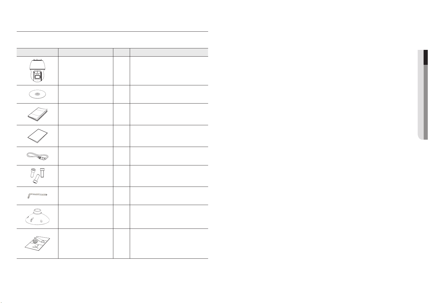
WHAT’S INCLUDED
Please check if your camera and accessories are all included in the product package.
(As for each sales country, accessories are not the same.)
Appearance Item Name Quantity Description
●● OVERVIEW
Main Body
Instruction book,
Installer S/W CD
Quick Guide
(Optional)
Warranty card
(Optional)
Cable for the testing monitor
Hexagon screw
L Wrench
Installation base
1
1
1
1
Used to test the camera connection to a portable display
1
3
Used for attaching the installation base to the camera
Used for fixing the installation base after attaching it to
1
1
device
the camera
Bracket for mounting outdoors
Waterproofing accessory
1
Install and use where there is high humidity.
English _7
overview
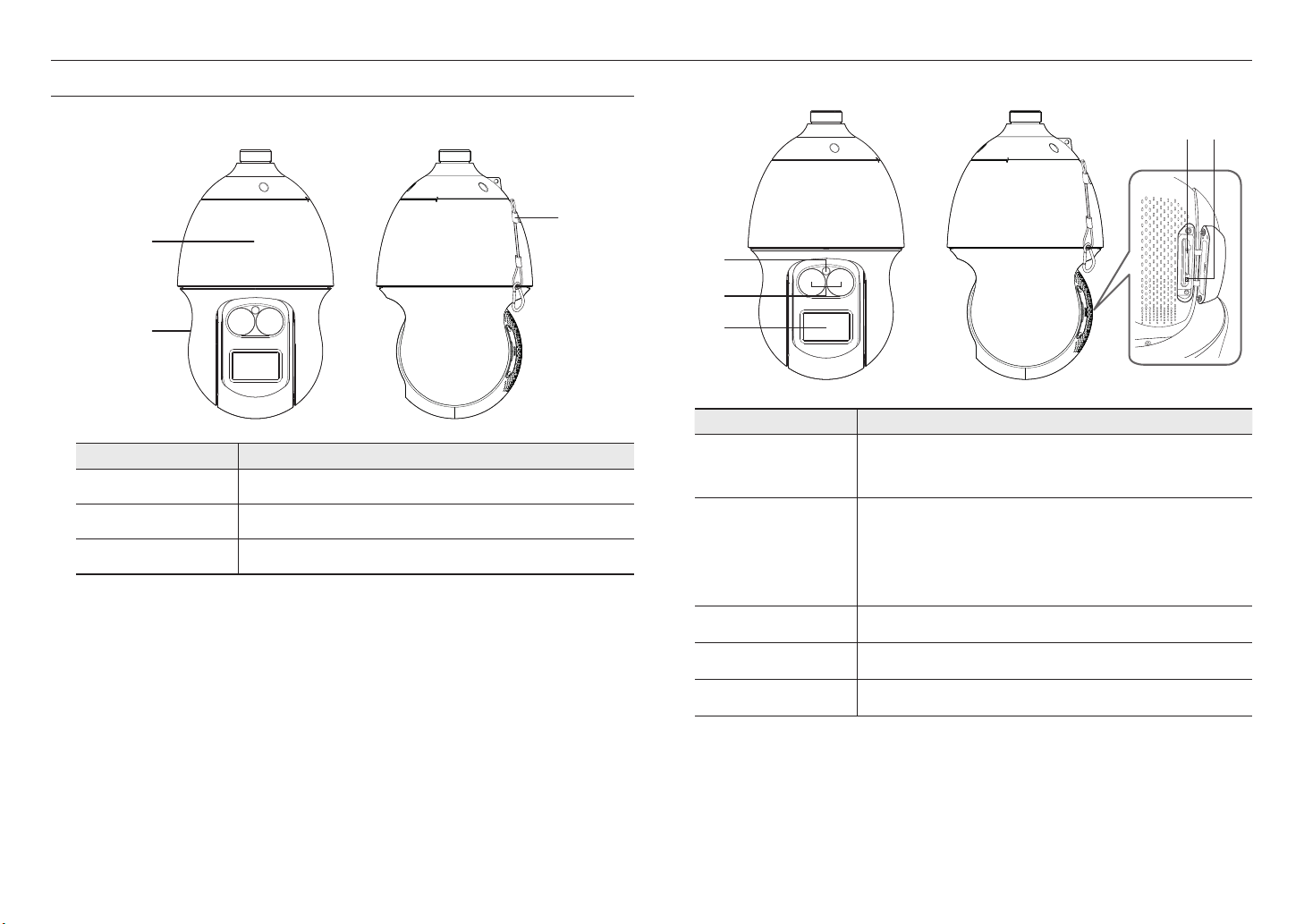
AT A GLANCE
Appearance
a
b
Item Description
Main unit
a
Shield cover
b
Safety Cable
c
c
Protects the internal PTZ mechanism from the direct sunlight, rain or external impact.
Shield cover for the lens and unit protection.
The cable prevents the product from dropping during installation.
Inside
c
d
e
a
b
Item Description
SD Memory Card
Compartment
Reset Button
Compartment for the SD memory card.
Refer to <Inserting/Removing a SD Memory Card> for the SD memory card insertion
M
position. (page 15)
The button restores all camera settings to the factory default.
Press and hold for about 5 seconds to reboot the system.
If you reset the camera, the network settings will be adjusted so that DHCP can be
J
enabled. If there is no DHCP server in the network, you must run the IP Installer
program to change the basic network settings such as IP address, Subnet mask,
Gateway, etc., before you can connect to the network.
a b
8_ overview
Illumination Sensor Detects incoming light to control the IR LED.
c
IR LED These infrared LED’s are controlled by the illumination sensor.
d
Lens Lens for the camera.
e
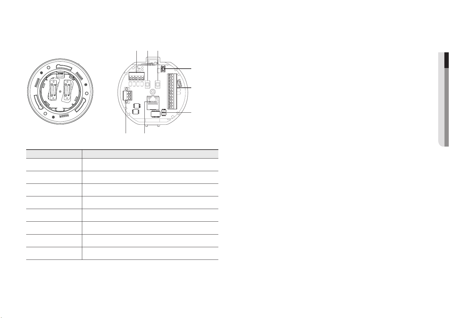
Bottom View of Installation
Base
Inner View of Installation Base
b
a c
●● OVERVIEW
D+ D- TXD+ TXD-GND
AC- FG AC-
gh
Item Description
Communications Ports Used for RS-485/422 communications.
a
Audio Input Port Used to connect the audio input cable.
b
Audio Output Port Used to connect the audio output cable.
c
Video Out Port Analog video output port. (for installation)
d
Alarm I/O Port Used to connect the alarm I/O cable.
e
Communications Setup
f
Switch
Network Connections Port for connection with the network using an Ethernet cable.
g
Set communication protocol (RS-485/422) and indicate whether to terminate.
d
2.NC
AUDIO OUTAUDIO IN
2.NO
2.COM
1.NO 1.NCIN1 IN2 GND IN3 IN4
e
1.COM
GND
f
Power Port Used to connect the power.
h
English _9
installation & connection
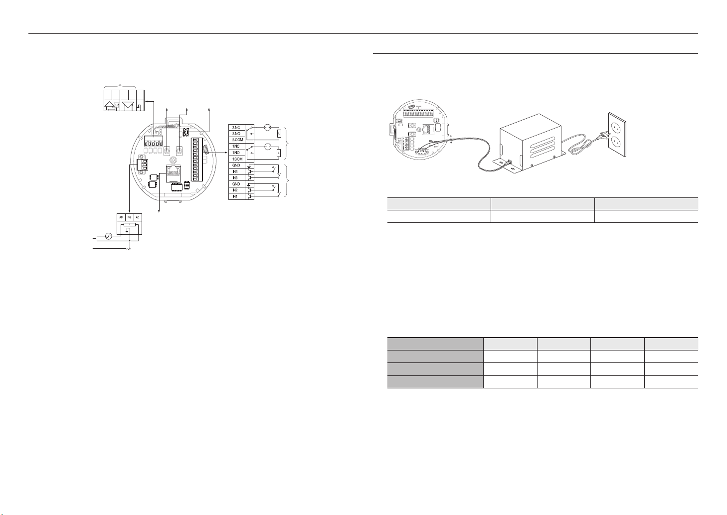
`Camera Wiring Interface Board
For the camera wiring, please refer to the picture below.
Refer to Control Signal
Connection Diagram
D+ D- TXD+ TXD- GND
Communications
Power Input
Ground
Select Normal Open in the setup menu.
`
J
The sensor input is activated during a short for contact type, or when it is at “Low” level for the active type.
-
Select Normal Close from the Setup menu.
`
The sensor input is activated when open for the contact type or when in high impedance state (open collector) for the
-
active type.
The maximum capacity of the alarm output terminal is 30V DC/2A, 125V AC/0.5A and 250V AC/0.25A.
`
When connecting alarm input and output cables, be sure to connect one cable to each terminal respectively.
`
To connect products over the camera’s capacity, please use an additional relay device.
`
If power and GND cables are connected inappropriately to the NC/NO or COM port, a fire or breakdown of equipment may
`
occur.
AC- FG AC-
Power
Supply
Audio INAudio
D+ D- TXD+ TXD- GND
AUDIO OUTAUDIO IN
ETHERNET
OUT
Video
Output
2.NC
2.NO
2.COM
1.NO 1.NCIN1 IN2 GND IN3 IN4
1.COM
GND
Alarm
Alarm output
Alarm Input
CONNECTING WITH OTHER DEVICE
Preparing Adapter and Cable
Connect the camera to the power adaptor. Then, plug the power cord of the adaptor to the wall outlet.
`
J
Check out the rated voltage and current before making connections.
Rated Power Allowable Input Voltage Current Consumption
AC 24V AC 22V ~ 26V 6 A
The product cannot be used at -50°C or below ambient temperature.
`
J
The product may not be defrosted depending on the installation area at -50°C.
`
Leave the product always turned on to maintain the internal temperature of -10°C or higher.
`
After the product is left alone under a low temperature environment, it will take up to 1 hours to normally operate.
`
The zooming speed of the IR dimmer may slow down at -40°C or lower environment.
`
If the product is turned on after being exposed to -20°C or below environment for some time, reset the time.
`
Electrical Resistance of Copper Wire at [20°C (68°F)]
Copper Wire Gauge (AWG) #24(0.22mm2) #22(0.33mm2) #20(0.52mm2) #18(0.83mm2)
Resistance (Ω/m) 0.078 0.050 0.030 0.018
Drop Voltage (V/m) 0.028 0.018 0.011 0.006
Recommended Distance (m) Less than 20 Less than 30 Less than 30 Less than 30
As shown in the table above, you may encounter a voltage-sag depending on the wire length.
`
If you use an excessively long wire for camera connection, the camera may not work properly.
Camera Operating Voltage: AC 24V±10%
-
Voltage drop measurements on the chart above may vary depending on the type and manufacture of the copper cable.
-
10_ installation & connection
Ethernet Connection
Connect the Ethernet cable to the local network or to the Internet.
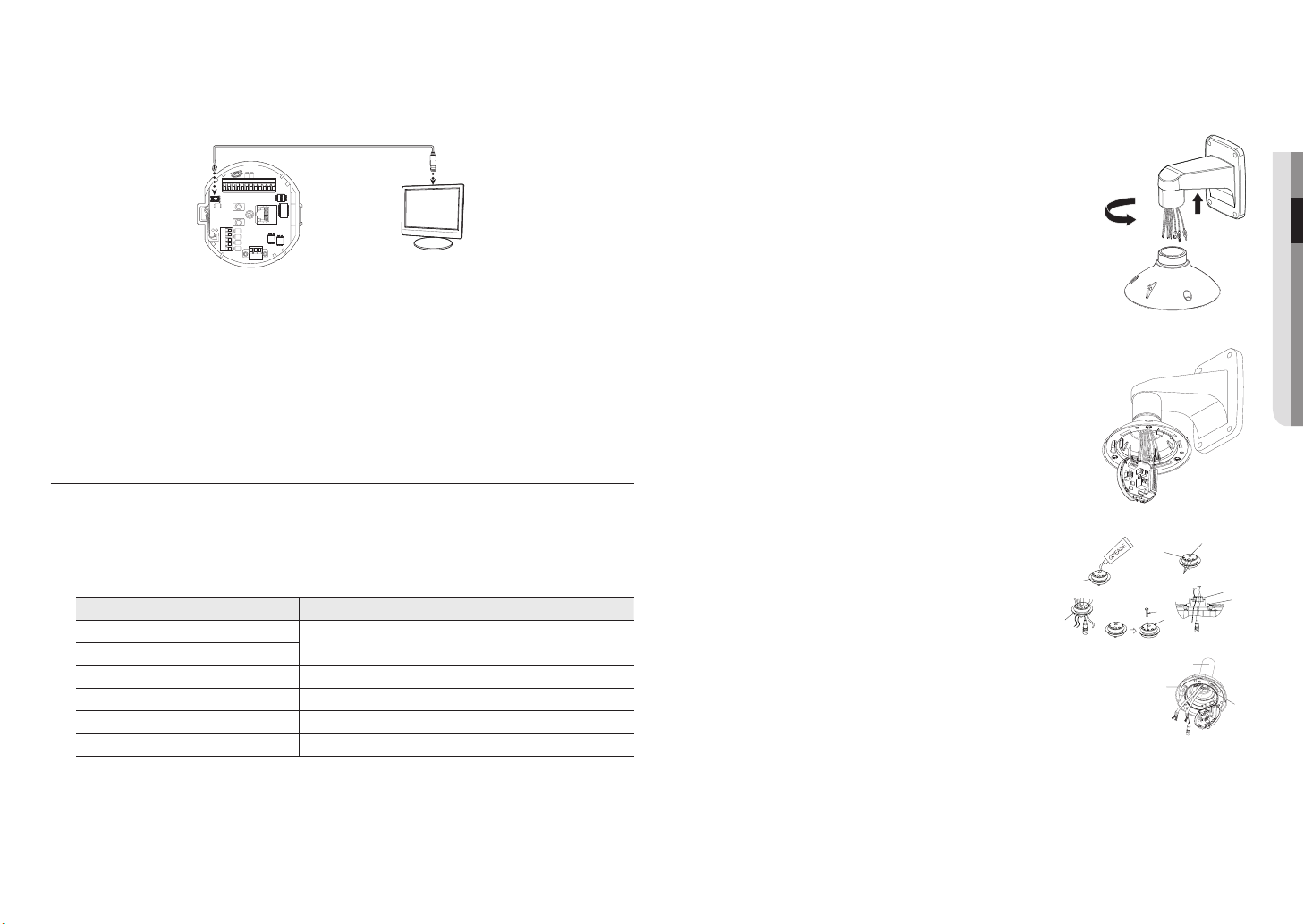
Connecting the installation monitor
하우징
또는 마운트
BUSH
인터페이스
Connect the cable to the camera’s rear video output terminal and the installation monitor’s video input
terminal.
GND
1.COM
1.NO 1.NCIN1 IN2 GND IN3 IN4
2.COM
2.NO
2.NC
AUDIO OUTAUDIO IN
D+ D- TXD+ TXD-GND
AC- FG AC-
The wiring varies depending on your monitor type and peripheral devices; please refer to the user manual for each device.
`
Please make sure the monitor and camera are turned off when connecting them.
`
This product is a network camera that transfers video over a network; the video output terminal is used to set the imaging
`
J
range of the camera at installation.
Using the terminal for monitoring purposes may cause problems such as degradation in video quality.
`
It is not suitable for 24-hour monitoring using professional CRT monitors or TFT/LCD portable monitors.
`
Use the network transfer screen for 24-hour monitoring and storage.
`
Monitor
INSTALLATION
Preparing & Installing Camera Bracket
For installation guidelines for brackets and housings, refer to the installation manual that is enclosed with the
bracket or housing.
`Available Bracket Models
Model Item
SBP-300WM1
SBP-300WM
SBP-300CM Ceiling Mount
SBP-300LM Parapet Mount
SBP-300KM Corner Mount
SBP-300PM Pole Mount
Wall Mount
Installing by wall mount
`Fix the installation base with the bracket
1. Fix the base with the bracket by turning it clockwise.
2. As shown in the picture below, gently press and lift up the handle of the
hinged door on the bottom of the installation base. Please refer to the
“Camera Wiring Interface Board” on page 10, connect the wires.
Do not connect the camera to a power outlet until the installation is complete.
`
J
Supplying power while the installation is in progress may cause fire or damage the
product.
Check cable connection method and install.
M
Note that BUSHINGs are provided for outdoor installations where exposed
`
to a moisture condition through the PIPE or MOUNT, install the HOUSING
using the BUSHING to prevent moisture entering.
Apply grease of proper dose on the BUSHING before assembling, and
-
run cables through each hole of the bushings. Use PINS to stop up
empty holes having no cable running.
Assemble the BUSHING to the top side of HOUSING’s inside as shown
-
in the diagram below. At the moment, apply pressure evenly on the
BUSHING to secure it tightly to the HOUSING as shown in the diagram.
BUSH
BUSH
BUSH
BUSH
POWER (AC24V)
인터페이스
INTERFACE
POWER
(AC24V)
핀
PIN
기타 케이블
ETC CABLE
BUSH
BUSH
하우징
HOUSING OR
또는 마운트
MOUNT
POE+ 또는 이더넷 케이블
Ethernet cable
●● INSTALLATION & CONNECTION
BUSH
BUSH
하우징
HOUSING
BUSH
BUSH
See “Optional Accessories for Installation” for the appearance of each bracket (unbundled). (page 13)
`
M
English _11
installation & connection
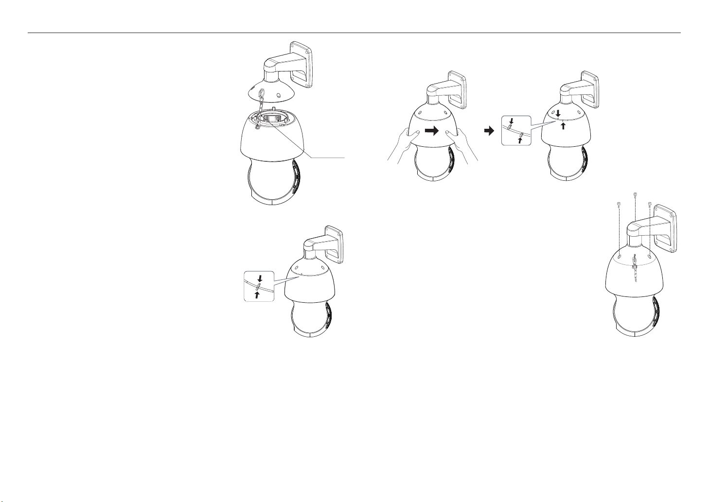
3. Connect the camera safety wire to the installation base.
4. Assemble Camera and Installation Base
Assemble the installation base and camera by matching the
installation direction guides.
5. Attach Camera
Rotate the main body of the camera clockwise to position the reference mark in the upper section and the
lower section as shown in the figure.
Safety Cable
6. Secure Camera and Installation Base
As shown in the picture below, secure the installation base and
camera using 3 hexagon screws.
12_ installation & connection
Notes for Waterproofing
This model is an integrated housing product for outdoor installation.
`When combining the main body and the wall mount for installation on the wall
1. Install the wall mount on the vertical wall. When it is installed
on an inclined wall, moisture may permeate into the main
body through the external cable.
2. Wrap the screw part of the housing with a sufficient amount of
Teflon tape for assembly.
3. Please make sure that the gasket is not disassembled from
the shield cover when the shield cover is separated and
mounted on the housing body.
4. Install the wall mount adapter for waterproofing, and apply the
silicon sealant between and around the wall and wall mount
for sealing.
Take particular caution to ensure that there is proper sealing if the
`
J
installed side is not flat.
Silicon
sealant
Wall mount
Screw
unit
`When combining the main body and the ceiling mounting adaptor for installation on the wall
1. Wrap the screw part of the housing with a sufficient amount
of Teflon tape for assembly.
2. Please make sure that the gasket is not disassembled from
the shield cover when the shield cover is separated and
mounted on the housing body.
3. Install the ceiling mount adapter for waterproofing, and apply
the silicon sealant between and around the wall and ceiling
mount for sealing.
Take particular caution to ensure that there is proper sealing if the
`
J
installed side is not flat.
Ceiling mount
adapter
Ceiling board
Screw
unit
Concrete wall
Teflon tape
Shield gasket
Concrete ceiling
Silicon
sealant
Teflon tape
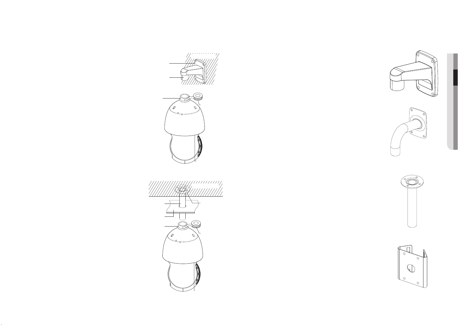
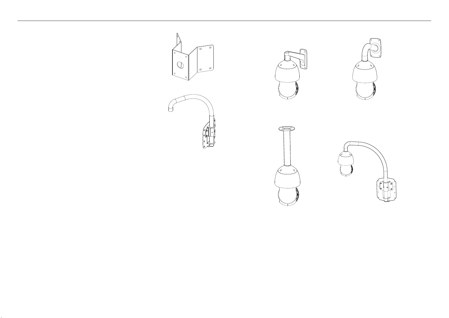
Optional Accessories for Installation
For your easier installation, you can purchase appropriate optional accessories available.
1. If installing the camera on the wall
• Wall mount (SBP-300WM1)
●● INSTALLATION & CONNECTION
• Wall mount (SBP-300WM)
2. If installing the camera on the ceiling
• Ceiling Mount (SBP-300CM)
3. If installing the wall mount (SBP-300WM/SBP-300WM1) on an at least 80mm-long cylinder
• Pole Mount (SBP-300PM)
Shield gasket
English _13
installation & connection
4. If installing the wall mount (SBP-300WM/SBP-300WM1) on a corner of the wall
• Corner Mount (SBP-300KM)
5. If installing on a building rooftop
• Parapet Mount (SBP-300LM)
`Mount Joint
Wall mount (SBP-300WM1)
Wall mount (SBP-300WM)
14_ installation & connection
Ceiling Mount (SBP-300CM)
Parapet Mount (SBP-300LM)
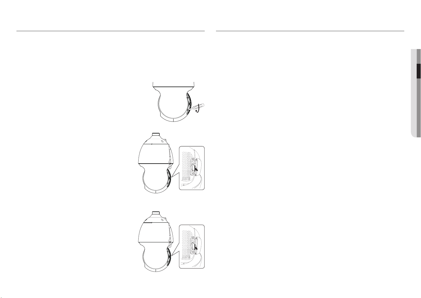
INSERTING/REMOVING A SD MEMORY CARD
Disconnect the power cable from the camera before inserting the SD memory card.
`
J
It is not recommended to remove the SD memory card in rainy or highly humid weather.
`
Tighten the screws when assembling the camera body, shield cover and SD holder bracket to prevent moisture penetration.
`
When mounting or dismounting an SD memory card, place the main body on the floor first to prevent part loss and falling
`
accident.
Inserting a SD Memory Card
1. Unfasten two screws on the SD holder bracket by turning them
counterclockwise using the driver.
Do not remove the screws.
`
J
2. Pull up the SD holder bracket and push the SD memory card to
the arrow direction as shown in the figure.
Do not insert the SD memory card while it’s upside down by force.
`
J
Otherwise, it may damage the SD memory card.
3. Assemble the camera in the reverse order of disassembly after
the SD memory card is inserted.
Tighten the screws when assembling the camera to prevent moisture
`
J
penetration.
MEMORY CARD INFORMATION (NOT INCLUDED)
What is a memory card?
The memory card is an external data storage device that has been developed to offer an entirely new way to
record and share video, audio, and text data using digital devices.
Selecting a memory card that’s suitable for you
Your camera supports SD/SDHC/SDXC memory cards.
You may, however, experience compatibility issues depending on the model and make of the memory card.
For your camera, we recommend you use a memory card from the following manufacturers:
SD/SDHC/SDXC Memory Card : Sandisk, Transcend
It is recommended to use a 4 to 128GB (HS class) memory card for this camera.
Playback performance can be affected depending on the speed of memory card, so use the high-speed
memory card.
Memory Card Use
SD and SDHC/SDXC memory cards feature a switch that disables writing data on to the media.
Having this switch to the Lock position will prevent accidental deletion of data stored in the memory card but
at the same time will also prevent you from writing data on to the media.
●● INSTALLATION & CONNECTION
Removing a SD Memory Card
Gently press down on the exposed end of the memory card as
shown in the diagram to eject the memory card from the slot.
Pressing too hard on the SD memory card can cause the card to shoot out
`
J
uncontrollably from the slot when released.
To turn off the camera or remove the SD memory card, set the card to
`
<Off> in <Storage> menu and press the [Apply] button. (page 51)
If you turn off the camera or remove the SD memory card that contains
`
data from the product, the data may be lost or damaged.
English _15
network connection and setup
You can set up the network settings according to your network configurations.
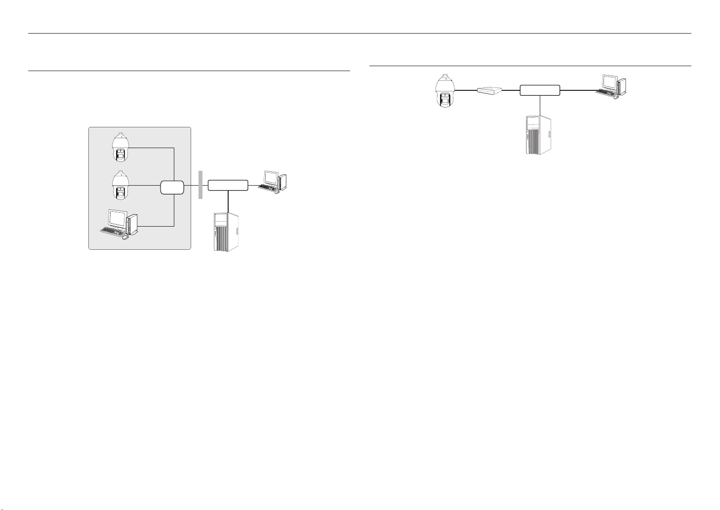
CONNECTING THE CAMERA DIRECTLY TO LOCAL AREA NETWORKING
Connecting to the camera from a local PC in the LAN
1. Launch an Internet browser on the local PC.
2. Enter the IP address of the camera in the address bar of the browser.
Camera
Switch
Camera
Local PC
<Local Network>
A remote PC in an external Internet out of the LAN network may not be able to connect to the camera installed in the intranet
`
M
if the port-forwarding is not properly set or a firewall is set.
In this case, to resolve the problem, contact your network administrator.
In the IP installer, you can use the initial password, “4321” to set IP Address, Subnet Mask, Gateway, HTTP Port, VNP Port, IP
`
type. After changing the network interface, for better security, access the web viewer and change the password.
By factory default, the IP address will be assigned from the DHCP server automatically.
`
If there is no DHCP server available, the IP address will be set to 192.168.1.100.
To change the IP address, use the IP Installer.
For further details on IP Installer use, refer to “Static IP Setup”. (Page 18)
INTERNET
External Remote PC
DDNS Server
(Data Center, KOREA)
CONNECTING THE CAMERA DIRECTLY TO A DHCP BASED DSL/CABLE
MODEM
DSL/Cable Modem
Camera
1. Connect the user PC directly with the network camera.
2. Run the IP Installer and change the IP address of the camera so that you can use the web browser on
your desktop to connect to the Internet.
3. Use the Internet browser to connect to the web viewer.
4. Move to [Setup] page.
5. Move to [Network] – [DDNS] and configure the DDNS settings.
6. Move to [Basic] – [IP & Port], and set the IP type to [DHCP].
7. Connect the camera, which was removed from your PC, directly to the modem.
8. Restart the camera.
For configuring the DDNS settings, refer to “DDNS”. (page 47)
`
M
For registering the DDNS settings, refer to “Registering with DDNS”. (page 48)
`
Refer to “IP & Port” for how to setup IP. (page 36)
`
INTERNET
DDNS Server
(Data Center, KOREA)
External Remote PC
16_ network connection and setup

CONNECTING THE CAMERA DIRECTLY TO A PPPoE MODEM
PPPoE Modem
Camera
INTERNET
External Remote PC
CONNECTING THE CAMERA TO A BROADBAND ROUTER WITH THE
PPPoE/CABLE MODEM
This is for a small network environment such as homes, SOHO and ordinary shops.
●● NETWORK CONNECTION AND SETUP
DDNS Server
(Data Center, KOREA)
1. Connect the user PC directly with the network camera.
2. Run the IP Installer and change the IP address of the camera so that you can use the web browser on
your desktop to connect to the Internet.
3. Use the Internet browser to connect to the web viewer.
4. Move to [Setup] page.
5. Move to [Network] – [DDNS] and configure the DDNS settings.
6. Move to [Basic] – [IP & Port] Setup Page, set the IP type to [PPPoE], and enter the network service’s ID
and password.
7. Connect the camera, which was removed from your PC, directly to the modem.
8. Restart the camera.
For configuring the DDNS settings, refer to “DDNS”. (page 47)
`
M
For registering the DDNS settings, refer to “Registering with DDNS”. (page 48)
`
Refer to “IP & Port” for how to setup IP. (page 36)
`
Camera
INTERNET
PPPoE or
Cable Modem
DDNS Server
(Data Center, KOREA)
External Remote PC
Camera
Local PC
Broadband
Router
PPPoE or
Cable Modem
Configuring the network settings of the local PC connected to a Broadband Router
Configuring the network settings of the local PC connected to a Broadband Router, follow the instructions
below.
• Select : <Network> <Properties> <Local Area Connection> <General> <Properties>
<Internet Protocol (TCP/IP)> <Properties> <Obtain an IP address automatically> or <Use the
following IP address>.
• Follow the instructions below if you select <Use the following IP address>:
ex1) If the address (LAN IP) of the Broadband Router is 192.168.1.1
IP address : 192.168.1.100
Subnet Mask : 255.255.255.0
Default Gateway : 192.168.1.1
ex2) If the address (LAN IP) of the Broadband Router is 192.168.0.1
IP address : 192.168.0.100
Subnet Mask : 255.255.255.0
Default Gateway : 192.168.0.1
ex3) If the address (LAN IP) of the Broadband Router is 192.168.xxx.1
IP address : 192.168.xxx.100
Subnet Mask : 255.255.255.0
Default Gateway : 192.168.xxx.1
For the address of the Broadband Router, refer to the product’s documentation.
`
M
For more information about port forwarding of the broadband router, refer to “Port Range Forward (Port Mapping) Setup”.
`
(Page 20)
English _17
network connection and setup
BUTTONS USED IN IP INSTALLER
a b c d e f g
Item Description
Device Name
a
Alias This function is not currently implemented.
b
Mode
c
MAC(Ethernet) Address
d
IP Address
e
Protocol
f
URL
g
IPv4 Scans for cameras with the IPv4 setting.
h
Model name of the connected camera.
Click the column to sort the list by model name.
However, search will be stopped if clicked during the search.
Displays either <Static>, <Dynamic> or <PPPoE> for the current network connection
status.
Ethernet address for the connected camera.
Click the column to sort the list by Ethernet address.
However, search will be stopped if clicked during the search.
IP address.
Click the column to sort the list by IP address.
However, search will be stopped if clicked during the search.
Network setting for the camera.
The factory default is “IPv4”.
Cameras with the IPv6 setting will be displayed “IPv6”.
DDNS URL address enabling access from the external Internet.
However, this will be replaced with the <IP Address> of the camera if DDNS registration
has failed.
h i
j k l m
Item Description
IPv6
i
Search
j
Auto Set The IP Installer automatically configures the network settings.
k
Manual Set You should configure the network settings manually.
l
Exit Exits the IP Installer program.
m
For the IP installer, use only the installer version provided in the installation CD or use the latest one if available. You can download
`
M
the latest version from the Hanwha Techwin web site.
Scans for cameras with the IPv6 setting.
Activated in an IPv6 compliant environment only.
Scans for cameras that are currently connected to the network.
However, this button will be grayed out if neither IPv4 nor IPv6 is checked.
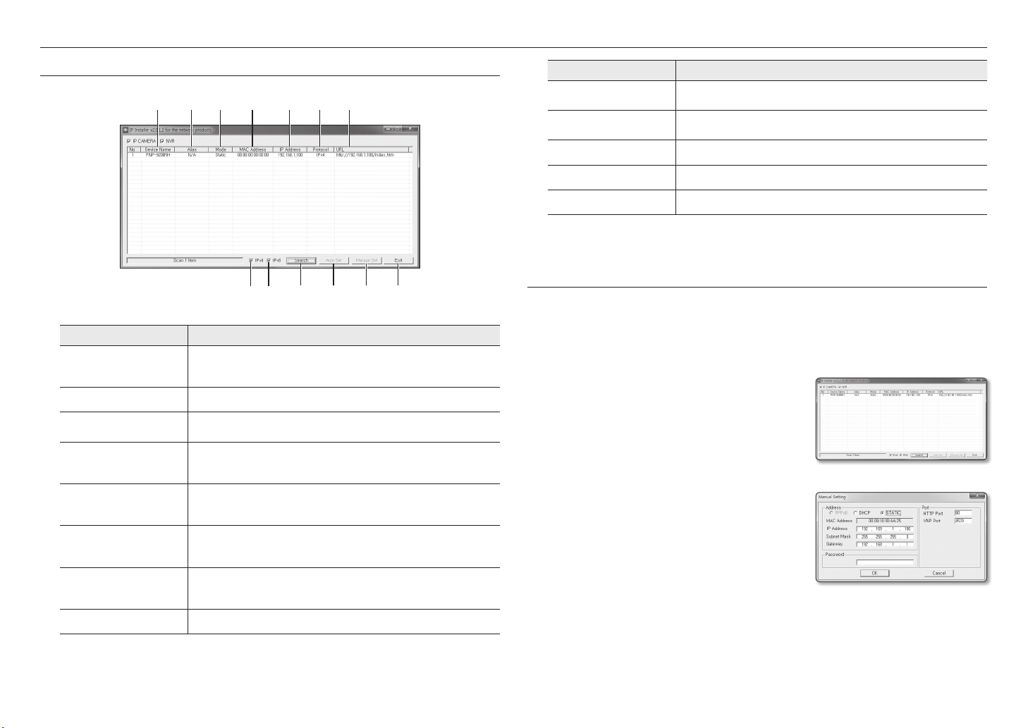
STATIC IP SETUP
Manual Network Setup
Run <IP Installer_v2.XX.exe> to display the camera search list.
At the initial startup, both [Auto Set] and [Manual Set] will be grayed out.
For cameras found with the IPv6 setting, these buttons will be grayed out as the cameras do not support this function.
`
M
1. Select a camera in the search list.
Check the MAC address of the camera on the camera’s label.
Both the [Auto Set] and [Manual Set] buttons will be
activated.
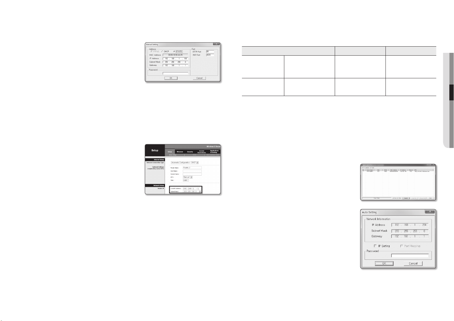
2. Click [Manual Set].
The Manual Setting dialog appears.
<IP Address>, <Subnet Mask>, <Gateway>, <HTTP
Port>, and <VNP Port> of the camera are displayed in the
preset values.
3. In the <Address> pane, provide the necessary information.
• MAC (Ethernet) Address : The MAC address imprinted on
the camera label is automatically displayed and requires no
user setting.
IP related parameters can be set only when DHCP is not checked.
`
M
18_ network connection and setup
If not using a Broadband Router
For setting <IP Address>, <Subnet Mask>, and <Gateway>, contact your network administrator.
4. In the <Port> pane, provide necessary information.
• HTTP Port : Used to access the camera using the Internet
browser, defaulted to 80.
• VNP Port : Used to control the video signal transfer,
defaulted to 4520.
5. Enter the password.
Enter the password of “admin” account, which was used to
access the camera.
For the security purposes, you are recommended to use a combination of numbers, alphabets uppercase and lowercase and
`
J
special characters for your password.
If you want to change the password, refer to “Administrator password change” of the user setup. (page 35)
`
6. Click [OK].
Manual network setup will be completed.
If using a Broadband Router
• IP Address : Enter an address falling in the IP range provided
by the Broadband Router.
ex) 192.168.1.2~254, 192.168.0.2~254,
192.168.XXX.2~254
• Subnet Mask : The <Subnet Mask> of the Broadband Router
will be the <Subnet Mask> of the camera.
• Gateway : The <Local IP Address> of the Broadband Router
will be the <Gateway> of the camera.
The settings may differ depending on the connected Broadband
`
M
Router model.
For more information, refer to the user manual of the applicable router.
For more information about port forwarding of the broadband router, refer to “Port Range Forward (Port Mapping) Setup”.
`
(Page 20)
If the Broadband Router has more than one camera connected
Configure the IP related settings and the Port related settings distinctly with each other.
ex)
Category Camera #1 Camera #2
IP related settings
Port related settings
If the <HTTP Port> is set other than 80, you must provide the <Port> number in the address bar of the Internet browser
`
M
before you can access the camera.
ex) http://IP address : HTTP Port
http://192.168.1.100:8080
IP Address
Subnet Mask
Gateway
HTTP Port
VNP Port
192.168.1.100
255.255.255.0
192.168.1.1
8080
4520
192.168.1.101
255.255.255.0
192.168.1.1
8081
4521
Auto Network Setup
Run <IP Installer_v2.XX.exe> to display the camera search list.
At the initial startup, both [Auto Set] and [Manual Set] will be grayed out.
For cameras found with the IPv6 setting, these buttons will be grayed out as the cameras do not support this function.
`
M
1. Select a camera in the search list.
Check the MAC address of the camera on the camera’s label.
Both the [Auto Set] and [Manual Set] buttons will be
activated.
2. Click [Auto Set].
The Auto Setting dialog appears.
The <IP Address>, <Subnet Mask>, and <Gateway> will
be set automatically.
3. Enter the password.
Enter the password of “admin” account, which was used to
access the camera.
●● NETWORK CONNECTION AND SETUP
For the security purposes, you are recommended to use a
`
J
combination of numbers, alphabets uppercase and lowercase and
special characters for your password.
If you want to change the password, refer to “Administrator
`
password change” of the user setup. (page 35)
4. Click [OK].
Auto network setup will be completed.
English _19
network connection and setup
DYNAMIC IP SETUP
Dynamic IP Environment Setup
• Example of the Dynamic IP environment
- If a Broadband Router, with cameras connected, is assigned an IP address by the DHCP server
- If connecting the camera directly to modem using the DHCP protocols
- If IPs are assigned by the internal DHCP server via the LAN
Checking the Dynamic IP
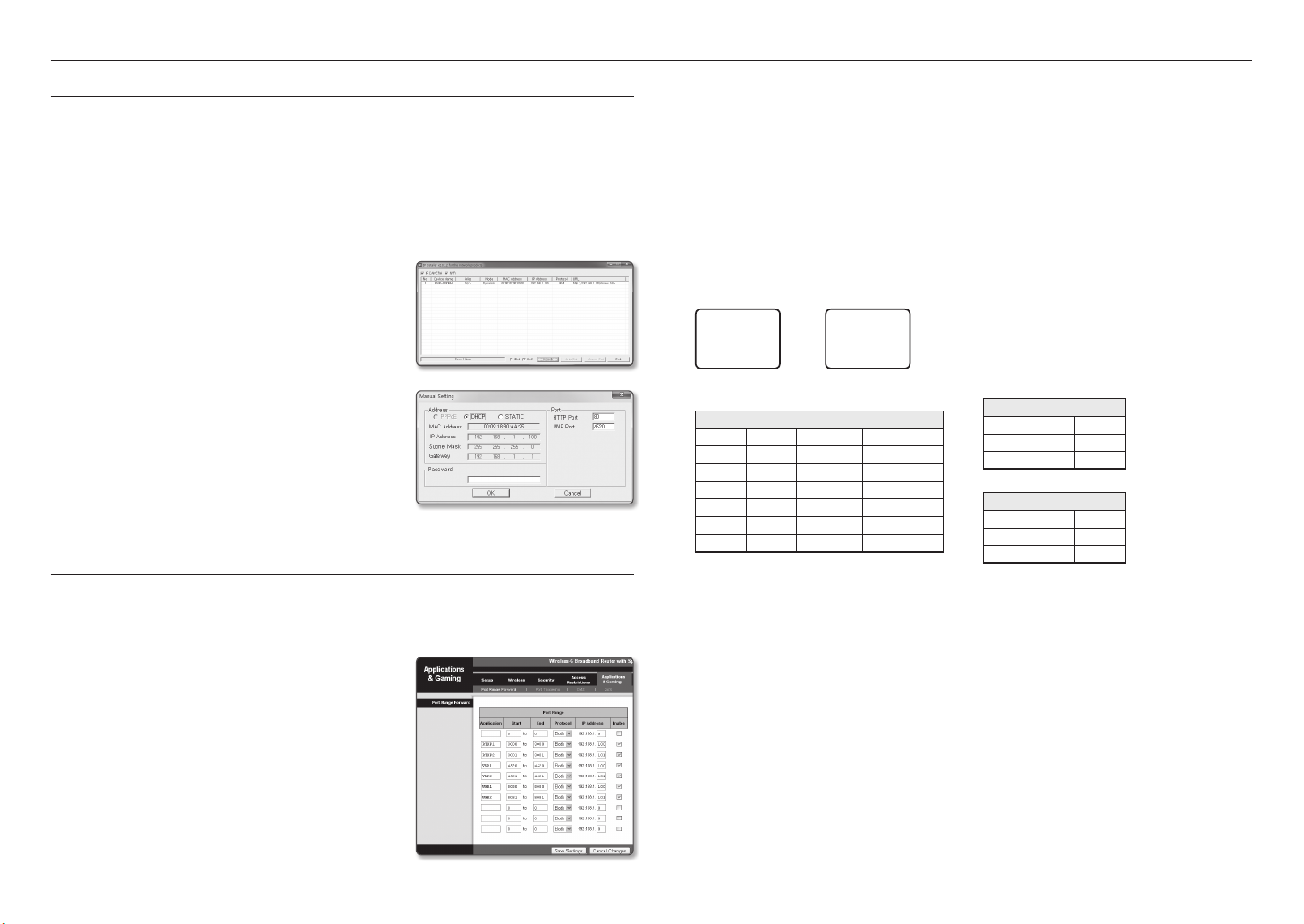
1. Run the IP Installer on the user’s local computer.
Cameras allocated with <Dynamic IP> address are shown in
the list.
2. Select a camera from the search result.
3. Click the [Manual Set] button and check the camera’s
<Dynamic IP> address.
If you uncheck <DHCP>, you can change IP to <Static>.
PORT RANGE FORWARD (PORT MAPPING) SETUP
If you have installed a Broadband Router with a camera connected, you must set the port range forwarding on the
Broadband Router so that a remote PC can access the camera in it.
Manual Port Range Forwarding
1. From the Setup menu of the Broadband Router, select
<Applications & Gaming> - <Port Range Forward>.
For setting the port range forward for a third-party Broadband
Router, refer to the user guide of that Broadband Router.
2. Select <TCP> and <UDP Port> for each connected camera
to the Broadband Router.
The number of each port to be configured to the IP router
should be set according to the port number designated
in <Setup> - <Basic> - <IP & Port> on the camera web
viewer.
3. When done, click [Save Settings].
Your settings will be saved.
Above sample instructions are based on the CISCO’s Broadband Router.
`
M
The settings may differ depending on the connected Broadband Router model.
`
For more information, refer to the user manual of the applicable router.
Setting up Port Range Forward for several network cameras
• You can set a rule of Port Forwarding on the Broadband Router device through its configuration web page.
• A user can change each port using the camera setting screen.
When Camera1 and Camera2 are connected to a router :
User
Start End Protocol IP Address
3000 3000 TCP/UDP 192.168.1.100
3001 3001 TCP/UDP 192.168.1.101
4520 4520 TCP/UDP 192.168.1.100
4521 4521 TCP/UDP 192.168.1.101
8080 8080 TCP/UDP 192.168.1.100
8081 8081 TCP/UDP 192.168.1.101
`
M
Broadband Router
Port forwarding can be done without additional router setup if the router supports the UPnP (Universal Plug and Play) function.
After connecting the network camera, set <Quick connect> of <Wisenet DDNS> to <On> in the “Setup Network
DDNS” menu.
Internet
Camera1 (192.168.1.100)
Camera2 (192.168.1.101)
HTTP port 8080
Device port 4520
RTSP port 3000
HTTP port 8081
Device port 4521
RTSP port 3001
20_ network connection and setup
CONNECTING TO THE CAMERA FROM A SHARED LOCAL PC
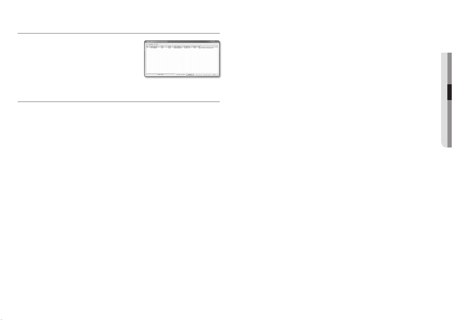
1. Run the IP Installer.
It will scan for connected cameras and display them as a list.
2. Double-click a camera to access.
The Internet browser starts and connects to the camera.
Access to the camera can also be gained by typing the camera’s IP
`
M
address in the address bar of the Internet browser.
CONNECTING TO THE CAMERA FROM A REMOTE PC VIA THE
INTERNET
Since using the IP Installer on a remote computer that is not in the Broadband Router’s network cluster is not
allowed, users can access cameras within a Broadband Router’s network by using the camera’s DDNS URL.
1. Before you can access a camera in the Broadband Router network, you should have set the port range
forward for the Broadband Router.
2. From the remote PC, launch the Internet browser and type the DDNS URL address of the camera, or the
IP address of the Broadband Router in the address bar.
ex) http://ddns.hanwha-security.com/ID
For registering the DDNS settings, refer to “Registering with DDNS”. (page 48)
`
M
●● NETWORK CONNECTION AND SETUP
English _21
web viewer
CONNECTING TO THE CAMERA
Normally, you would
1. Launch the Internet browser.
2. Type the IP address of the camera in the address bar.
ex) • IP address (IPv4) : 192.168.1.100
http://192.168.1.100
- the Login dialog should appear.
IP address (IPv6) : 2001:230:abcd: ffff:0000:0000:ffff:1111
•
http://[2001:230:abcd:ffff:0000:0000:ffff:1111] - the Login
dialog should appear.
If the HTTP port is other than 80
1. Launch the Internet browser.
2. Type the IP address and HTTP port number of the camera in the address bar.
ex) IP address : 192.168.1.100:HTTP Port number(8080)
http://192.168.1.100:8080 - the Login dialog should appear.
Using URL
1. Launch the Internet browser.
2. Type the DDNS URL of the camera in the address bar.
ex) URL address : http://ddns.hanwha-security.com/ID
- the Login dialog should appear.
Network connection is disabled in the LAN only environment.
`
J
Connecting via UPnP
1. Run the client or operating system in support of the UPnP protocol.
2. Click the camera name for search.
In the Windows operating system, click the camera name searched from the network menu.
- The login window is displayed.
Connecting via Bonjour
1. Run the client or operating system in support of the Bonjour protocol.
2. Click the camera name for search.
In the Mac operating system, click the camera name searched from the Bonjour tab of Safari.
- The login window is displayed.
To check the DDNS address
If the camera is connected directly to the DHCP cable modem, DSL modem, or PPPoE modem, the IP
address of your network will be changed each time you try to connect to the ISP (Internet Service Provider)
server.
If this is the case, you will not be informed of the IP address changed by DDNS.
Once you register a dynamic IP-based device with the DDNS server, you can easily check the changed IP
when you try to access the device.
To register your device to the <DDNS> server, visit http://ddns.hanwha-security.com and register your device
first, and then set the Web Viewer’s <Network> - <DDNS> to <Wisenet DDNS>, as well as providing
<Product ID> that had been used for DDNS registration.
22_ web viewer
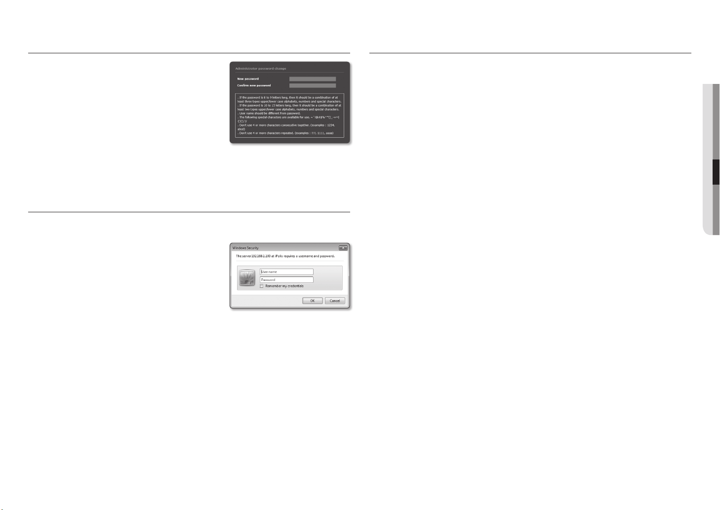
PASSWORD SETTING
When you access the product for the first time, you must register the
login password.
When the “Password change” window appears, enter the new
password.
For a new password with 8 to 9 digits, you must use at least 3 of
`
J
the following: uppercase/lowercase letters, numbers and special
characters. For a password with 10 to 15 digits, you must use at
least 2 types of those mentioned.
Special characters that are allowed. : ~`!@#$%^*()_-+=|{}[].?/
-
For higher security, you are not recommended to repeat the same characters or consecutive keyboard inputs for your
`
passwords.
If you lost your password, you can press the [RESET] button to initialize the product. So, don’t lose your password by using a
`
memo pad or memorizing it.
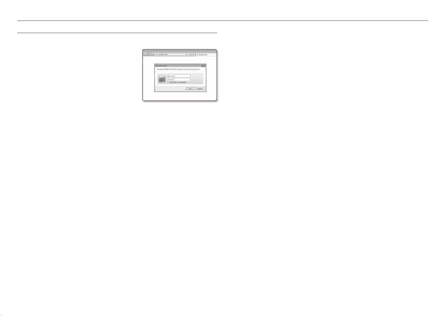
LOGIN
Whenever you access the camera, the login window appears.
Enter the User ID and password to access the camera.
1. Enter “admin” in the <User name> input box.
The administrator ID, “admin”, is fixed and can not be
changed.
2. Enter the password in the <Password> input field.
3. Click [OK].
If you have logged in successfully, you will the Live Viewer
screen.
When you access the camera web viewer, pay special attention to the
`
J
security by checking whether the image data is encrypted.
PLUG-IN SUPPORT SPECIFICATIONS FOR EACH BROWSER
The existing plug-in web viewer and a new plug-in free web view is embedded together.
Therefore, it is possible to use the web viewer even in the latest browser environment that does not support plugins such as Chrome and EDGE.
According to the browser environment, the following differences may be observed.
• Chrome, EDGE browser : Although they don’t support plug-ins, you can use a web viewer as a plug-in
free web viewer is embedded.
As the plug-in free webviewer has lower performance than the plug-in webviewer, it has a limit on the monitoring of high
`
J
quality profiles and playback of saved videos.
To monitor high quality profiles and play saved videos, use either a plug-in webviewer or SmartViewer.
Plugin-free webviewer : The optimal profile for the plugin-free webviewer is as follows.
-
H.264 - 1280x720 20fps
H.265 - 800x600 30fps
Plug-in free profile generation conditions: If the selected profile exceeds the optimal plugin-free resolution, an optimal
-
resolution profile is automatically created and monitored.
Plug-in free playback conditions: A recorded video with an HD resolution or lower
-
• IE, Firefox, or Safari browser : You can use a web viewer even if you don’t install the existing plug-in web
viewer.
To monitor/play saved video seamlessly, you are required to install a plug-in.
`
J
●● WEB VIEWER
If you check the “Remember my credentials” option when your input is done, in future you will be logged in automatically
`
M
without being prompted to enter the login information.
You will experience the best video quality if the screen size is 100%. Reducing the ratio may cut the image on the borders.
`
English _23
web viewer
INSTALLING WebViewer PLUGIN
To access to the plug-in webviewer and play a live video (H.264/H.265) or a recorded video, an installation
message will be prompted. At this time you need to install the webviewer plug-in to use the function properly.
1. When the monitoring page is accessed for the very first time, the installation page is displayed. Click [Click
Here] to begin installation.
If the plug-in installation file download status is suspended at 99% in the Internet Explorer browser, retry it after selecting
`
J
“Release SmartScreen filter” in “Tool SmartScreen filter”.
2. Click [Run] in the message window.
3. Click [Yes] when the notice window saying that all browser windows will be closed.
Steps 4 and 5 will be skipped if no Web Viewer Plug-in is installed.
`
M
4. When the old version of the Web Viewer Plug-in is installed, a notice window saying the old version will be
deleted is displayed.
Click [Yes] when the notice window is displayed.
5. Click [OK].
The old version of Web Viewer Plug-in is deleted.
6. Click [Install] to begin installation of the Web Viewer Plug-in.
7. Click [Finish].
Web Viewer Plug-in installation is completed.
In your internet explorer, if you need to move to the installation screen after installing the webviewer plugin, check whether
`
J
webviewer_activexplugin_lib.control in the “Tool Additional Function Management” menu is “Activated”. If not, and if there
is a persisting problem, then select “Tools Internet Options General” and delete all the search records.
USING A PLUG-IN FREE WEBVIEWER
If you access the camera from Google Chrome or MS Edge web browser, you can check and control the camera
image in real time without installing separate plug-in(s).
1. Enter your username and password to log in.
2. When you are logged in, a camera live view screen appears.
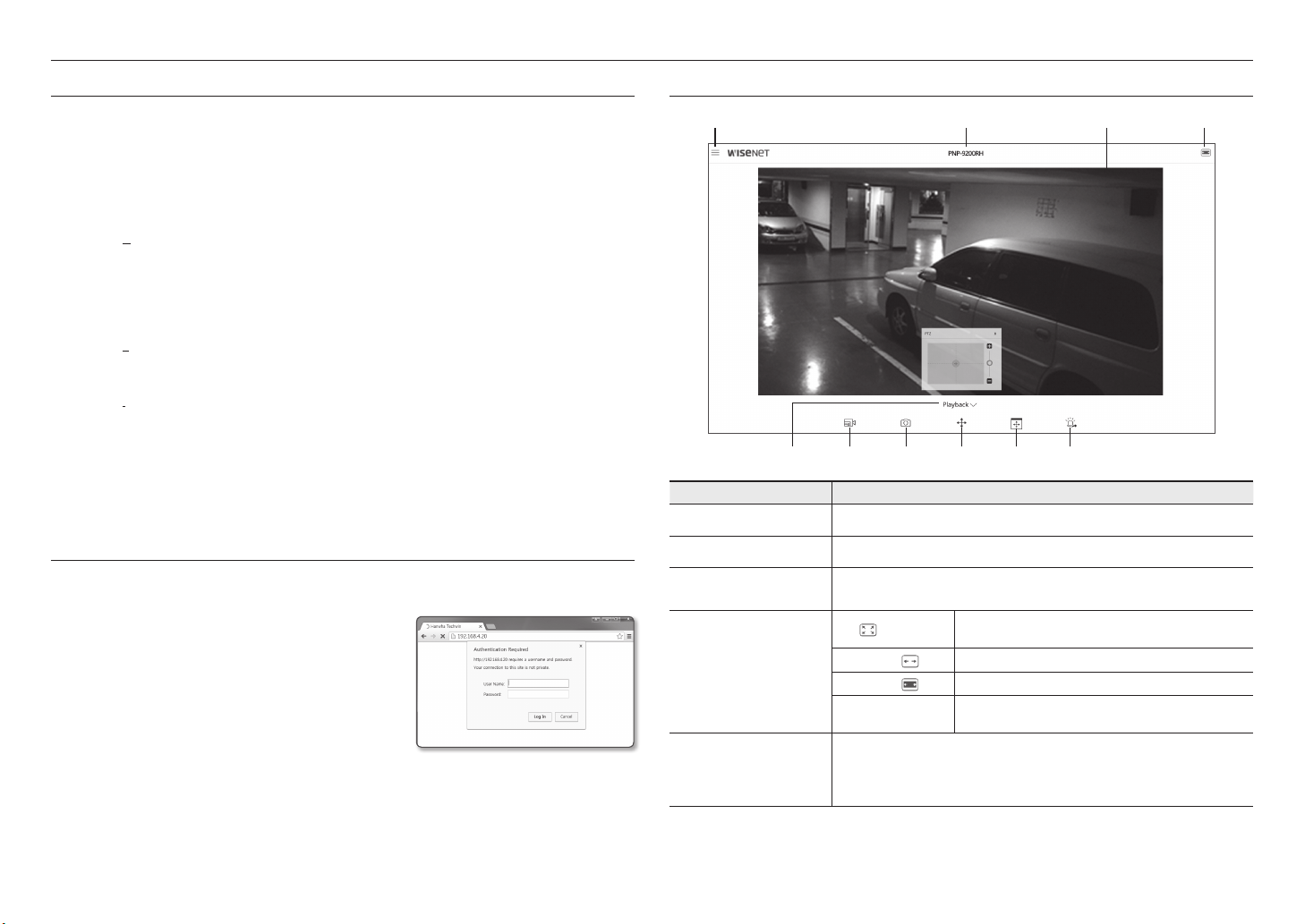
USING THE LIVE SCREEN (PLUG-IN FREE WEBVIEWER)
a b c d
f g h i je
Item Description
Setup Move to the Setup screen.
a
Camera Model Name Displays the model name of the camera accessed.
b
Viewer Screen
c
Switch View Mode
d
Playback
e
Displays the Live video on the screen.
You can use the mouse wheel to activate the digital zooming in Viewer screen.
`
)
FIt (
Original Size (
Aspect Ratio (
Full Screen
Move to the screen where you can search for the video recording saved in your SD memory card
or NAS.
To search a recorded video, go to the play screen, place the mouse over the video and double
`
click.
A view mode in which the size of the camera video automatically fits
to the web browser size.
) View mode in which the video is played in the actual resolution.
) View mode that adjusts the aspect ratio to best fit the resolution.
Double click on the video screen, and the current video will be
played in the full screen of the monitor.
24_ web viewer
 Loading...