

Page 1

NX58H9500W*
NX58H9950W*
NX58K9500W*
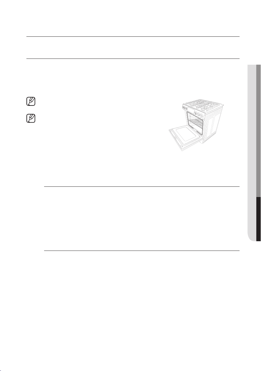
Slide-In Gas Range
installation manual
imagine the possibilities
Thank you for purchasing this Samsung product.
Page 2
WARNING: If the information in this manual is not followed
exactly, a fire or explosion may result causing property
damage, personal injury or death.
• DO NOT store or use gasoline or other flammable vapors
and liquids in the vicinity of this or any other appliance.
• WHAT TO DO IF YOU SMELL GAS:
- DO NOT try to light any appliance.
- DO NOT touch any electrical switch.
- DO NOT use any phone in your building.
- Immediately call your gas supplier from a neighbor’s
phone. Follow the gas supplier’s instructions.
- If you cannot reach your gas supplier, call the fire
department.
• Installation and service must be performed by a qualified
installer, service agency, or the gas supplier.
ANTI-TIP DEVICE
WARNING
ALL RANGES CAN TIP, RESULTING IN PERSONAL
INJURY.
TIPPING RANGES CAN CAUSE BURNS FROM SPILLS,
PERSONAL INJURY, AND/OR DEATH.
INSTALL AND CHECK THE ANTI-TIP BRACKET
FOLLOWING THE INSTRUCTIONS AND TEMPLATE
SUPPLIED WITH THE BRACKET
English - 2
.
Page 3

• To prevent accidental tipping of the range, attach an
approved anti-tip device to the floor. (See Installing the AntiTip Device in the Installation Instructions.) Check for proper
installation by carefully tipping the range forward. The anti-tip
device should engage and prevent the range from tipping
over.
• If the range is pulled out away from the wall for any reason,
make sure the anti-tip device is reengaged after the range
has been pushed back into place.
• Follow the installation instructions found in the Installation
Manual. Failure to follow these instructions can result in
death, serious personal injury, and / or property damage.
• DO NOT step / sit / lean on the door or drawer to prevent
accidental tipping of the range.
English - 3
Page 4

contents
BEFORE YOU BEGIN
6
IMPORTANT SAFETY
INFORMATION
7
6 About this manual
7 Read all instructions before using this
appliance
7 Symbols used in this manual
7 State of California Proposition 65 Warning
(US only)
7 Commonwealth of Massachusetts
8 General safety
9 Fire safety
9 Gas safety
10 Electrical and grounding safety
11 Installation safety
12 Location safety
12 Cooktop safety
14 Oven safety
15 Warming drawer/lower drawer safety
15 Self-cleaning oven safety
GAS RANGE COMPONENTS
16
English - 4
16 Overview
17 Gas range specifications
Page 5

INSTALLATION
REQUIREMENTS
18
18 Location requirements
20 Optional rear filler kit
21 To avoid breakage
22 Gas requirements
23 Special gas requirements (gas models
sold in massachusSetts)
23 Electrical requirements
TOOLS AND MATERIALS
26
INSTALLATION
INSTRUCTIONS
27
26 What’s in the box
27 Installing your gas range
27 Step 1. Unpack the range
27 Step 2. Connect the range to gas supply
29 Step 3. Convert to lp gas (optional)
30 Step 4. Install the anti-tip device
31 Step 5. Plug in and place
32 Step 6. Level the range
33 Step 7. Assemble the surface burners
33 Step 8. Check the ignition of surface
burners and oven burners
35 Step 9. Final installation checklist
36 Adjusting the oven burner air adjustment
shutters
English - 5
Page 6

before you begin
ABOUT THIS MANUAL
READ THESE INSTRUCTIONS COMPLETELY AND CAREFULLY.
Important note to the installer
• Read all instructions contained in these installation instructions before
installing the range.
• Remove all packing materials from the oven compartments before connecting
the electric and gas supply to the range.
• Observe all governing codes and ordinances.
• Be sure to leave these instructions with the consumer.
• Installation of this appliance requires basic mechanical skills.
• Proper installation is the responsibility of the installer.
• Product failure due to improper installation is not covered under the Warranty.
Important note to the consumer
Keep these instructions with your user manual for future reference.
• As when using any appliance generating heat, there are certain safety
precautions you should follow.
• Be sure your range is installed and grounded properly by a qualified installer
or service technician.
• Make sure the wall coverings around the range can withstand the heat
generated by the range.
• Cabinet storage space above the surface burners should be a minimum of 30
in (76.2 cm).
Important note to the servicer
The electrical diagram is in an envelope attached to the back of the range.
English - 6
Page 7
important safety information
READ ALL INSTRUCTIONS BEFORE USING THIS APPLIANCE
• All electrical and gas equipment with moving parts can be dangerous. Please read
the important safety instructions for this appliance in this manual. The instructions
must be followed to minimize the risk of injury, death, or property damage.
• Save this manual. Please Do Not Discard.
SYMBOLS USED IN THIS MANUAL
WARNING: Hazards or unsafe practices that may result in severe personal
injury or death.
CAUTION: Hazards or unsafe practices that may result in electric shock,
personal injury or property damage.
NOTE: Useful tips and instructions
These warning icons and symbols are here to prevent injury to you and others. Please
follow them explicitly. After reading this section, keep it in a safe place for future
reference.
STATE OF CALIFORNIA PROPOSITION 65 WARNING (US ONLY)
01 BEFORE YOU BEGIN & IMPORTANT SAFETY INFORMATION
• WARNING : This product contains chemicals known to the State of California to cause
cancer and birth defects or other reproductive harm.
• Gas appliances can cause low-level exposure to Proposition 65 listed substances,
including but not limited to, benzene, carbon monoxide, formaldehyde and soot,
substances resulting from the incomplete combustion of natural gas or LP fuels.
COMMONWEALTH OF MASSACHUSETTS
• This product must be installed by a licensed plumber or gas fitter qualified or licensed by
the State of Massachusetts. When using ball-type gas shut-o valves, you must use the
T-handle type. Multiple flexible gas lines must not be connected in series.
English - 7
Page 8
GENERAL SAFETY
WARNING To reduce the risk of fire, electric shock, personal injuries, and/or death,
obey the following precautions.
• Do not touch any part of the range, including
but not limited to, oven burners, surface burners,
or interior surfaces during or immediately after
cooking.
• Know the location of the gas shut-o valve and
how to shut it o.
• Make sure the anti-tip device is properly
installed on the range. See the installation
instructions for more information.
• Do not let children near, in, or on the range. Do not let children play with the range or
any part(s) of the range. Do not leave children unattended in an area where the range is in
use. For children’s safety, we recommend utilizing the control/door lockout feature.
• Remove all packaging materials from the range before operating to prevent ignition of
these materials. Keep all packaging materials out of children’s reach. Properly dispose the
packaging materials after the range is unpacked.
• Do not store any object of interest to children on the cooktop or backguard of the range.
Children climbing on the range to reach items could be killed or seriously injured.
• Do not operate the range if the range or any part of the range is damaged,
malfunctioning, or missing parts.
• Do not use the range as a space heater. This range is to be used for cooking purposes
only.
• Do not use oven cleaners or oven liners in or around any part of the oven.
• Use only dry pot holders.
• Do not use the range to heat unopened food containers.
• Do not strike the oven glass.
• When disposing of the range, cut o the power cord and remove the door.
• Unplug or disconnect power before servicing.
• Make sure all meat and poultry is cooked thoroughly. Meat should always be cooked to
an internal temperature of 160 °F (71 °C). Poultry should always be cooked to an internal
temperature of 180 °F (82 °C).
English - 8
Page 9
FIRE SAFETY
WARNING To reduce the risk of fire, electric shock, personal injuries, and/or death,
obey the following precautions.
• Do not store, place, or use flammable or
combustible materials such as paper, plastic,
pot holders, linens, curtains, gasoline or other
flammable vapors or liquids near the range.
• Do not wear loose fitting or hanging garments
while using the range.
• To avoid grease buildup, regularly clean the
vents.
• Do not let pot holders or other flammable materials touch a heating element. Do not use
a towel or other bulky cloths in place of a pot holder.
• Do not use water on a grease fire. To put out a grease fire, turn o the heat source and
smother the fire with a tight-fitting lid or use a multipurpose dry chemical or foam-type fire
extinguisher.
• If a grease fire should occur in the oven, turn o the oven by pressing the OFF/CLEAR
button.
Keep the oven door closed until the fire goes out.
If necessary, use a multipurpose dry chemical or foam-type fire extinguisher.
• Do not heat unopened food containers - buildup of pressure may cause container to
burst and result in injury.
01 BEFORE YOU BEGIN & IMPORTANT SAFETY INFORMATION
GAS SAFETY
WARNING To reduce the risk of fire, electric shock, personal injuries, and/or death,
obey the following precautions.
If you smell gas:
• Close the valve and do not use the range.
• Do not light a match, candle, or cigarette.
• Do not turn on any gas or electric appliances.
• Do not touch any electrical switches or plug a
power cord into an outlet.
• Do not use any phone in your building.
• Evacuate the room, building, or area of all
occupants.
• Immediately call your gas supplier from a neighbor’s phone. Follow the gas supplier’s
instructions.
• If you cannot reach your gas supplier, call the fire department.
English - 9
Page 10
Checking for gas leaks
• Leak testing of the appliance shall be conducted according to the manufacturer’s
instructions. Do not use a flame to check for gas leaks. Use a brush to spread a soapy
water mixture around the area you are checking. If there is a gas leak, you will see small
bubbles in the soapy water mixture at the leak point.
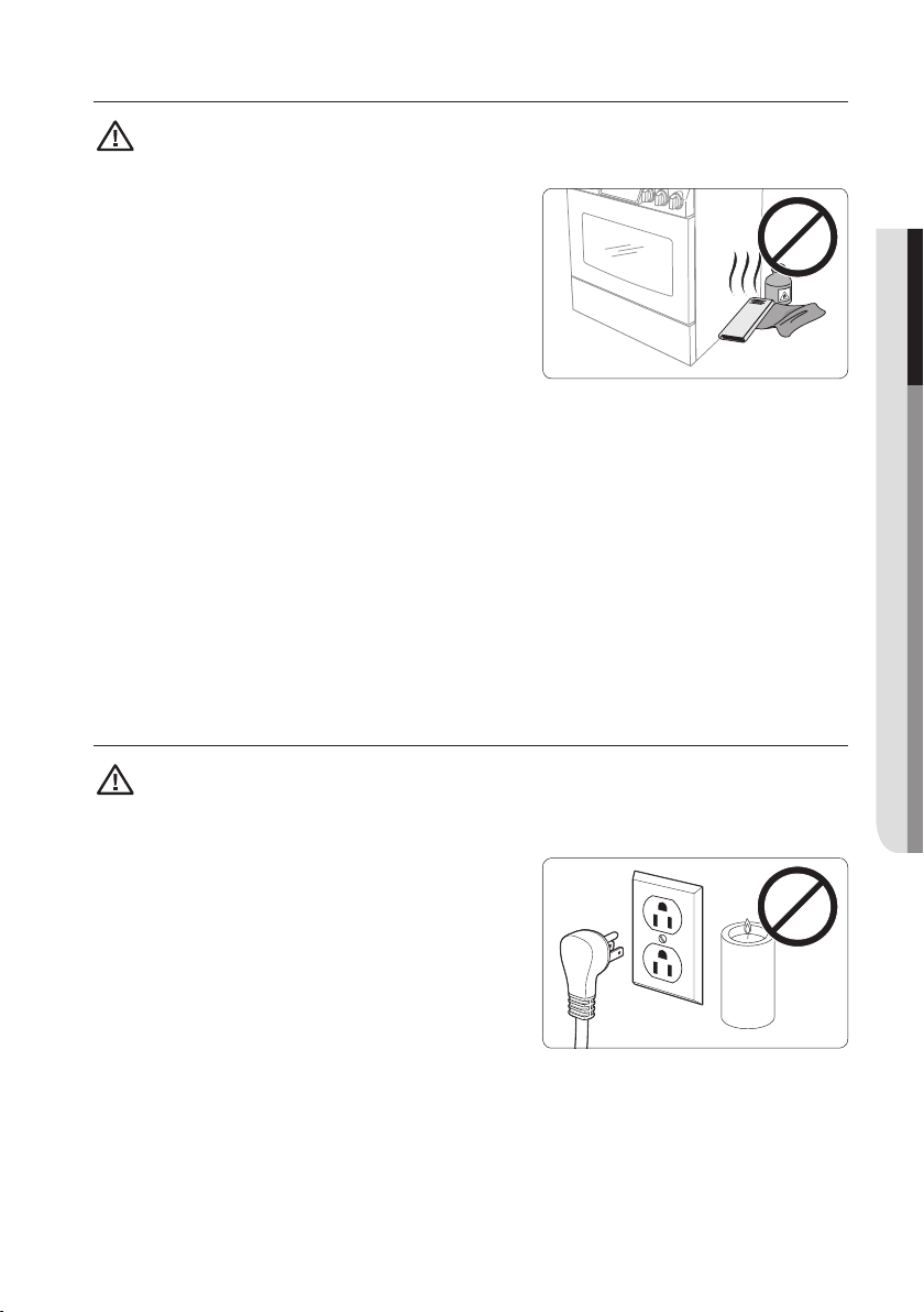
ELECTRICAL AND GROUNDING SAFETY
WARNING To reduce the risk of fire, electric shock, personal injuries, and/or death,
obey the following precautions.
• Plug into a grounded 3-prong outlet.
• Do not remove the ground prong.
• Do not use an adapter or an extension cord.
• Do not use a damaged power plug, power cord,
or loose power outlet.
• Do not modify the power plug, power cord, or
power outlet in any way.
• Do not put a fuse in a neutral or ground circuit.
• Use a dedicated 120-volt, 60-Hz, 20-amp, AC, fused electrical circuit for this range. A
time-delay fuse or circuit breaker is recommended. Do not plug more than one appliance
into this circuit.
• Do not connect the ground wire to plastic plumbing lines, gas lines, or hot water pipes.
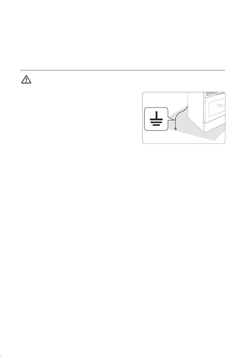
• This range must be Earth grounded. In the event of a malfunction or breakdown,
grounding will reduce the risk of electrical shock by providing a path for the electric
current. This range is equipped with a cord having a grounding plug. The plug must be
firmly plugged into an outlet that is properly installed and grounded in accordance with
the local codes and ordinances. If you are unsure whether your electrical outlet is properly
grounded, have it checked by a licensed electrician.
• The range is supplied with a 3-pronged grounded plug. This cord must be plugged into
a mating, grounded 3-prong outlet that meets all local codes and ordinances. If codes
permit the use of a separate ground wire, we recommend that a qualified electrician
determine the proper path for this ground wire.
• Electrical service to the range must conform to local codes. Barring local codes, it should
meet the latest ANSI/NFPA No. 70 – Latest Revision (for the U.S.) or the Canadian
Electrical Code CSA C22.1 – Latest Revisions.
• It is the personal responsibility of the range owner to provide the correct electrical service
for this range.
English - 10
Page 11
INSTALLATION SAFETY
WARNING To reduce the risk of fire, electric shock, personal injuries, and/or death,
obey the following precautions.
• Have your range installed and properly grounded
by a qualified installer, in accordance with
the installation instructions. Any adjustment and
service should be performed only by qualified gas
range installers or service technicians.
• Do not attempt to service, modify, or replace
your range or any part of your range unless it
is specifically recommended in this manual. All
other service should be referred to a qualified
technician.
• Always use new flexible connectors when installing a gas appliance. Do not use old
flexible connectors.
• Make sure the anti-tip device is properly installed on the range. See the installation
instructions for more information.
• Due to the size and weight of the range, have two or more people move the range.
• Remove all tape and packaging materials.
• Remove all accessories from the cooktop, oven, and/or lower drawer. Grates and
griddles are heavy. Use caution when handling them.
• Make sure no parts came loose during shipping.
• Make sure your range is correctly installed and adjusted by a qualified service technician
or installer for the type of gas (natural or LP) you will use. For your range to utilize LP
gas, the installer must replace the 5 surface burner orifices and 2 oven orifices with the
provided LP orifice set, and reverse the GPR adapter. These adjustments must be made
by a qualified service technician in accordance with the manufacturer’s instructions and
all codes and requirements of the authority having jurisdiction. The qualified agency
performing this work assumes the gas conversion responsibility.
• Installation of this range must conform with local codes or, in the absence of local
codes, with the National Fuel Gas Code, ANSI Z223.1/NFPA.54, latest edition. In
Canada, installation must conform with the current Natural Gas Installation Code, CAN/
CGA-B149.1, or the current Propane Installation Code, CAN/CGA-B149.2, and with local
codes where applicable. This range has been design-certified by ETL according to ANSI
Z21.1, latest edition, and Canadian Gas Association according to CAN/CGA-1.1, latest
edition.
01 BEFORE YOU BEGIN & IMPORTANT SAFETY INFORMATION
English - 11
Page 12
LOCATION SAFETY
WARNING To reduce the risk of fire, electric shock, personal injuries, and/or death,
obey the following precautions.
• This range is for indoor, household use only.
Do not install the range in areas exposed to the
weather and/or water.
• Do not install the range in a place which is
exposed to a strong draft.
• Select a level, well-constructed floor that can
support the range’s weight. Synthetic flooring,
such as linoleum, must withstand 180 °F (82
°C) temperatures without shrinking, warping, or
discoloring. Do not install the range directly over
interior kitchen carpeting unless a sheet of ¼ inch
plywood or a similar insulator is placed between
the range and carpeting.
• Select a location where a grounded, 3- prong outlet is easily accessible.
• If the range is located near a window, do not hang long curtains or paper blinds on that
window.
• For the range to ventilate properly, make sure the range’s vents are not blocked, and that
there is enough clearance at the top, back, sides, and underneath the range. The vents
allow the necessary exhaust for the range to operate properly with correct combustion.
• Make sure the wall coverings around the range can withstand heat up to 200 °F (93 °C)
generated by the range.
• Cabinet storage above the surface of the range should be avoided. If cabinet storage
above the range is necessary: allow a minimum clearance of 40 inches (102 cm) between
the cooking surface and the bottom of cabinets; or install a range hood that projects
horizontally a minimum of 5 inches (12.7 cm) beyond the bottom of the cabinets.
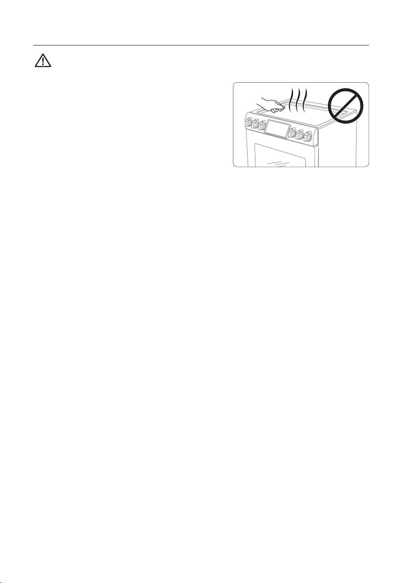
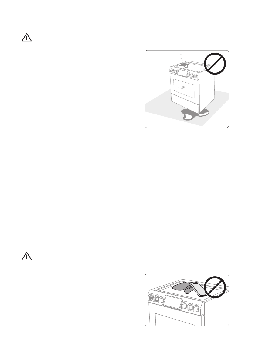
COOKTOP SAFETY
WARNING To reduce the risk of fire, electric shock, personal injuries, and/or death,
obey the following precautions.
• Make sure all burners are o when not in use.
• Do not use aluminium foil to line the grates or
any part of the cooktop.
• Do not leave burners unattended on medium or
high heat settings.
• Before igniting, make sure all burner caps are
properly in place and all burners are level.
English - 12
Page 13

• Always use the LITE position when igniting the burners and make sure the burners have
ignited. If ignition fails, turn the knob to OFF and wait until the gas has dissipated.
• When you set a burner to simmer, do not turn the knob quickly. Make sure the flame
stays on.
• Do not place any objects other than cookware on the cooktop.
• This cooktop is designed to cook with a wok or wok ring attachment. If foods are flamed,
they should only be flamed under a ventilation hood that is on.
• Before removing or changing cookware, turn o the burners.
• Remove food and cookware immediately after cooking.
• Before removing any parts of the burner for cleaning, make sure the range is o and
completely cool.
• After cleaning the burner spreader, make sure it is completely dry before re-assembling.
• Make sure the spark mark on the dual burner spreader is placed beside the electrode
when it is assembled.
• To avoid carbon monoxide poisoning, do not pour water into the cooktop well while
cleaning.
• Select cookware that is designed for top-range cooking. Use cookware that is large
enough to cover the burner grates. Adjust the burner flames so that the flames do not
extend beyond the bottom of the cookware.
• To avoid cookware discoloration, deformity, and/or carbon monoxide poisoning, do not
use cookware that is exceedingly larger than the grate.
• Make sure cookware handles are turned to the side or rear of the cooktop, but not over
other surface burners.
• Stand away from the range while frying.
• Always heat frying oils slowly, and watch as they heat. If you are frying foods at high heat,
carefully watch during the cooking process. If a combination of fats or oils is to be used
during frying, mix them together before heating.
• Use a deep-fryer thermometer whenever possible. This prevents overheating the fryer
beyond the smoking point.
• Use a minimum amount of oil when shallow pan-frying or deep-frying. Avoid cooking
unthawed food or food with excessive amounts of ice.
• Before moving cookware full of fats or oils, make sure it has completely cooled.
• To prevent delayed eruptive boiling, always allow heated liquids to stand at least 20
seconds after you have turned o the burner so that the temperature in the liquid can
stabilize. In the event of scalding, follow these first aid instructions:
1) Immerse the scaled area in cool or lukewarm water for at least 10 minutes.
2) Do not apply any creams, oils, or lotions.
3) Cover with a clean, dry cloth.
01 BEFORE YOU BEGIN & IMPORTANT SAFETY INFORMATION
English - 13
Page 14
OVEN SAFETY
WARNING To reduce the risk of fire, electric shock, personal injuries, and/or death,
obey the following precautions.
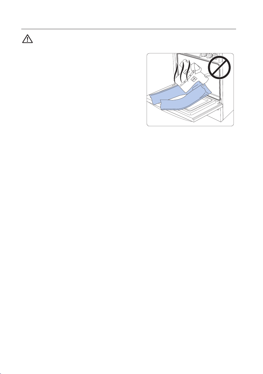
• Do not use the oven for non-cooking purposes
such as drying clothes or storage. Use the oven
for cooking purposes only.
• Make sure the inner portion of the split oven-
rack is in the proper position within the outer
rack.
• Make sure the oven racks are placed on the
same level on each side.
• Do not damage, move, or clean the door
gasket.
• Do not spray water on the oven glass while the oven is on or just after you have turned
it o.
• Do not use aluminium foil or foil liners anywhere in the oven. Do not use aluminium foil or
like material to cover any holes or passages in the oven bottom or to cover an oven rack.
• Stand away from the oven when opening the oven door.
• Keep the oven free from grease buildup.
• When repositioning the oven racks, make sure the oven is completely cool.
• Only use cookware that is recommended for use in gas ovens.
• To avoid damaging the burner control knobs, always bake and/or broil with the oven door
closed.
• Do not broil meat too close to the burner flame. Trim excess fat from meat before
cooking.
• When using cooking or roasting bags in the oven, follow the manufacturer’s directions.
English - 14
Page 15
WARMING DRAWER/LOWER DRAWER SAFETY
WARNING To reduce the risk of fire, electric shock, personal injuries, and/or death,
obey the following precautions.
• The warming drawer is designed to keep hot
foods at serving temperature. Always start with
hot food. Cold or room-temperature foods cannot
be heated, warmed, or cooked in the warming
drawer. Bacteria will grow very rapidly in food that
is between 40 and 140
• Do not use the drawer for non-cooking purposes
such as drying clothes or storage. Use the drawer
for cooking purposes only.
• Do not touch the interior drawer surface or heating element.
• To avoid steam burns, use caution when opening the drawer.
• Do not use aluminium foil to line the drawer.
• Do not use the drawer in the oven. Do not put the drawer in the oven during a self-
cleaning cycle.
• Do not leave containers of fat drippings in or near the drawer.
°F
.
SELF-CLEANING OVEN SAFETY
WARNING To reduce the risk of fire, electric shock, personal injuries, and/or death,
obey the following precautions.
01 BEFORE YOU BEGIN & IMPORTANT SAFETY INFORMATION
• The self-cleaning feature operates the oven at
temperatures high enough to burn away food soils
in the oven. The range is extremely hot during a
self-cleaning cycle. Do not touch any surfaces of
the range during a self-cleaning cycle.
• Keep children away from the oven during a selfcleaning cycle.
• Before starting a self-cleaning cycle, remove all
racks, cookware, and utensils from the oven. Only porcelain-coated oven racks may be
left in the oven.
• Before starting a self-cleaning cycle, wipe grease and food soils from the oven.
• Do not self-clean with the lower/warming drawer placed in the oven.
• When opening the door after a self-cleaning cycle, stand away from the oven.
• If the self-cleaning cycle malfunctions, turn o the oven, disconnect the power supply,
and contact a qualified service technicia.
English - 15
Page 16
gas range components
OVERVIEW
MODEL NX58H9950W* / NX58H9500W* / NX58K9500W*
Cooktop Burner Placement
Heavy-Duty continous
drawer Knob (1)
cast Grates
Warming
Control panel
Oven Racks (3)
Oven Door
Surface Burner
Knobs (5)
Cooktop Burners (under grates)
Burner Locations and Output Ratings
Location Output Rating
Left-Front (LF) 15000 BTU
Left-Rear (LR) 9500 BTU
Center (CTR) 9500 BTU
Right-Rear (RR) 5000 BTU
Right-Front (RF)
Broil (Upper)
Bake (Lower)
Warming Drawer
(with Full Extension Roller Guide Rails)
(Natural Gas)
(NX58H9500W* Only)
16500 BTU
18000 BTU
19000 BTU
18000 BTU
6
9
7
3
10
11
12
13
5
4
1
2
8
1 Touch display 8 Warming drawer
2 Surface burner knobs (5 pcs) 9 Broil oven burner
3 Warming drawer knob (1 pc) 10 Oven light
4 Surface burners 11 Convection fan / Convection heater
5 Oven vent 12 Oven rack system
6 Cooling vent 13 Bake oven burner
7 Door
English - 16
Page 17
GAS RANGE SPECIFICATIONS
MODEL NX58H9950W*
DESCRIPTION Gas Slide-in Range
13
OVERALL DIMENSIONS 29
/16 "(W) x 36 3/
NET WEIGHT 233 lb (105.5Kg)
ELECTRICAL Refer to the rating label.
GAS, NG (NATURAL GAS) 5–13 in WC
GAS, LP (LIQUID PROPANE) 10–13 in WC
SURFACE BURNERS (NG) (LF)–15,000 BTU / (LR)–9,500 BTU / (CTR)–9,500 BTU /
(RR)–5,000 BTU / (RF)–19,000 BTU
SURFACE BURNERS (LP) (LF)–11,500 BTU / (LR)–7,500 BTU / (CTR)–7,500 BTU /
(RR)–4,000 BTU / (RF)–14,500 BTU
OVEN BURNERS (NG) Broil (Upper)–16,500 BTU / Bake (Lower)–18,000 BTU
OVEN BURNERS (LP) Broil (Upper)–11,500 BTU / Bake (Lower)–15,000 BTU
MODEL NX58H9500W*/NX58K9500W*
DESCRIPTION Gas Slide-in Range
13
OVERALL DIMENSIONS 29
/16 "(W) x 36 3/
NET WEIGHT 225 lb (102Kg)
ELECTRICAL Refer to the rating label.
GAS, NG (NATURAL GAS) 5–13 in WC
GAS, LP (LIQUID PROPANE) 10–13 in WC
SURFACE BURNERS (NG) (LF)-15,000 BTU / (LR)–9,500 BTU / (CTR)–9,500 BTU /
(RR)–5,000 BTU / (RF)–18,000 BTU
SURFACE BURNERS (LP) (LF)–11,500 BTU / (LR)–7,500 BTU / (CTR)–7,500 BTU /
(RR)–4,000 BTU / (RF)–14,500 BTU
OVEN BURNERS (NG) Broil (Upper)–16,500 BTU / Bake (Lower)–18,000 BTU
OVEN BURNERS (LP) Broil (Upper)–11,500 BTU / Bake (Lower)–15,000 BTU
" (H) x 26 3/8 " (D)
16
"(H) x 26 3/8 "(D)
16
02 GAS RANGE COMPONENTS
English - 17
Page 18
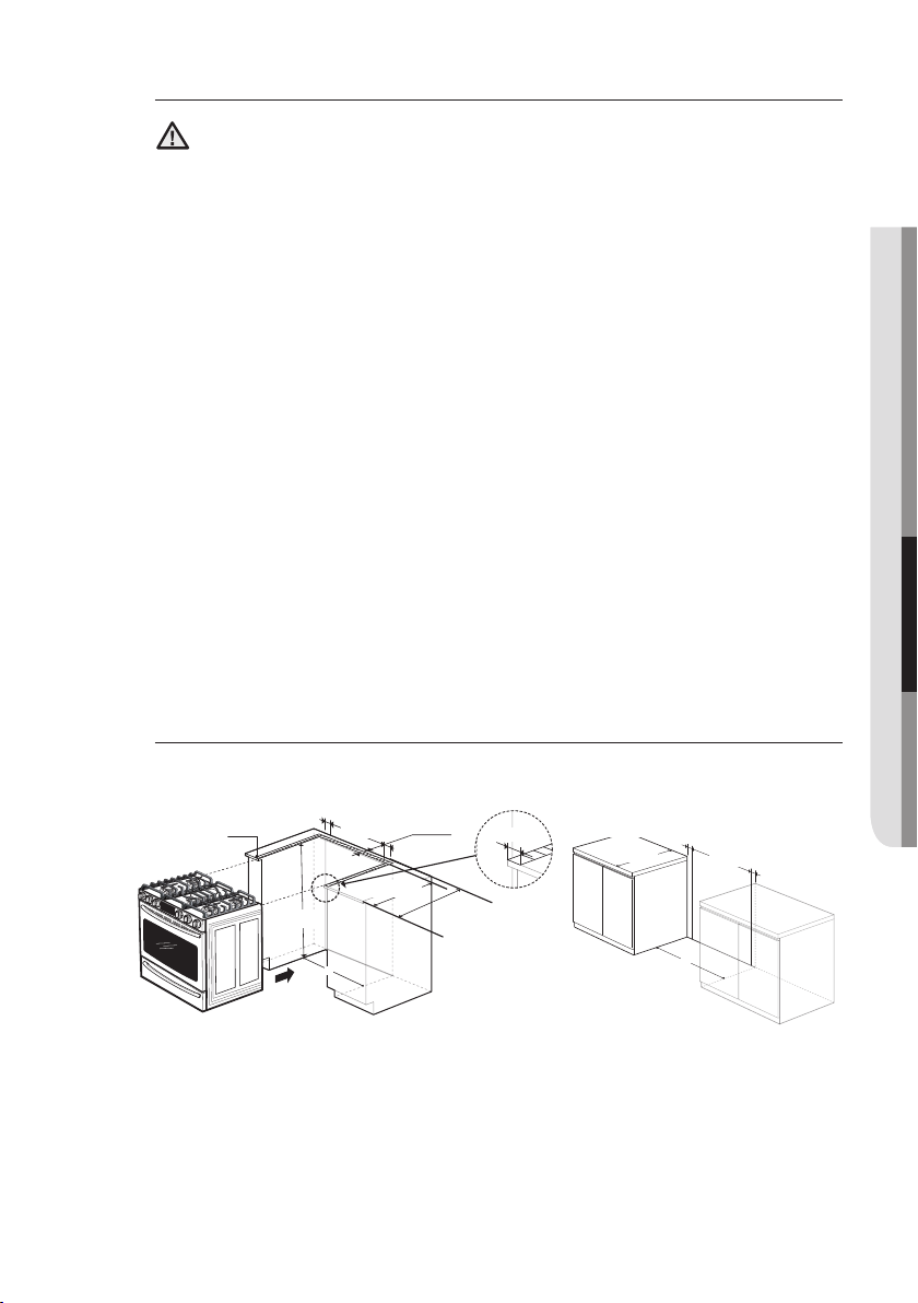
installation requirements
LOCATION REQUIREMENTS
Clearances and dimensions
For OTR over Gas Stove, please follow local GAS CODE.
BEFORE YOU BEGIN to install this appliance, refer to the following information,
dimensions, and clearances. Do not locate the range where it may be
subject to strong drafts. Provide adequate clearances between the range and
adjacent combustible surfaces. These dimensions must be met for safe use of
the range. The location of the electrical outlet and gas piping may be adjusted to
meet the following dimensions and clearances.
For installation in Canada, a free-standing range is not to be installed
closer than 4.7 in (12 cm) from any adjacent surface.
This range has been designed to comply with the maximum allowable
wood cabinet temperature of 194 °F (90 °C). Make sure the wall covering,
CAUTION
countertops, and cabinets around the range can withstand the heat (up to
194 °F [90 °C]) generated by the range. If not, discoloration, delamination, or
melting may occur.
13 in (33 cm)
Overhead
Cabinet
Depth
23.2 in
(58.9 cm)
Side
Clearance
Above
Cooking
Surface to
Wall
36 in
(91.4 cm)
4 in
(10.2 cm)
24 in
(61 cm)
Lower
Cabinet
Depth
30 in
(15.2 cm)
6 in
30 in (76.2 cm)
30 in (76.2 cm)
18 in (45.7 cm)
0 in (0 cm)
Clearance
Below
Cooking Top
and at Rear
and Sides of
Range
IMPORTANT: MAKE SURE the unit is supported by the leveling legs and NOT
by the cooktop itself.
English - 18
0 in
(15.2 cm)
Page 19
Minimum dimensions
1/2”min
If overhead cabinets are provided, a range hood should also be provided
that projects horizontally a minimum of 5 in (12.7 cm) beyond the front of
WARNING
the cabinets. This will dissipate any heat buildup in the overhead cabinets
to prevent death, personal injury, and/or fire hazard. The ventilating hood
must be constructed of sheet metal not less than 0.0122" thick. Install
above the cooktop with a clearance of not less than 1/4" between the hood
and the underside of the combustible material or metal cabinet. The hood
must be at least as wide as the appliance and centered over the appliance.
Clearance between the cooking surface and the ventilation hood surface
must never be less than 24 inches.
Exception 1 :
over the cooktop shall conform to the installations packed with that appliance.
• 30-in (101.6-cm) minimum clearance between the top of the cooking
surface and the bottom of an unprotected wood or metal cabinet; or If no
30-in(101.6-cm) minimum clearance, 24-in (61-cm) minimum when the
bottom of the wood or metal cabinet is protected by not less than 0.25-in
(0.64-cm) flame-retardant millboard covered with not less than no. 28
MSG sheet steel, 0.015-in (0.038-cm) stainless steel, 0.024-in (0.061cm) aluminum, or 0.020-in (0.051-cm) copper.
• 18-in (45.7-cm) minimum between the countertop and the adjacent
cabinet bottom.
Exception 2 : For island installation, maintain 2-1/2" minimum from cutout
to back edge of countertop and 4" minimum from cutout to side edges of
countertop.
Installation of a listed microwave oven or cooking appliance
03 INSTALLATION REQUIREMENTS
Installation guide
SLIDE-IN CUTOUT FREESTANDING CUTOUT
Hatched Faces should be
flat and leveled.
A: Cabinet opening
IMPORTANT: If your cabinet have height over 36-4/5", this range cannot be installed
without supporting unit like hard block.
3”
24”
35-7/8”
A
30" (76.2 cm)
1”min
3”
23 3/16”
English - 19
25”
25”
3”
24”
3”
A
Page 20
Recommended locations for gas piping and electrical
outlets
(For models NX58H9950W*, NX58H9500W*, NX58K9500W*)
Recommended area for
120 V electrical outlet
on rear wall
17 in x 9 in
(43.2 cm x 22.9 cm)
Gas Wall Area
12 in
(30.5 cm)
Recommended area
for through-the-wall
and through-the-floor
connection of gas pipe
stub and shut-o valve.
CAUTION
CAUTION
You must use the rear filler kit to install the range in a
17 in x 2 in
(43.2 cm x 5.1 cm)
Gas Floor Area
30 in (76.2 cm)
Cabinet Opening
freestanding cutout cabinet. For more information, see “Optional rear filler kit” as
shown below.
Optional rear filler kit
Used to fill gap between the range back and wall. Adds a filler strip to
the rear of the range. This kit can only be used when the opening in the
WARNING
countertop is 25" deep.
If the countertop depth is greater than 25", there will be a gap between the
filler kit and the back wall.
English - 20
Page 21
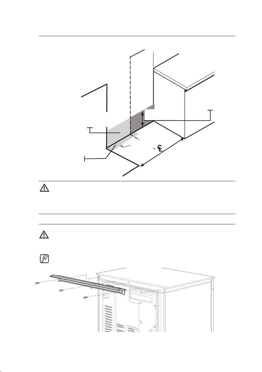
TO AVOID BREAKAGE
03 INSTALLATION REQUIREMENTS
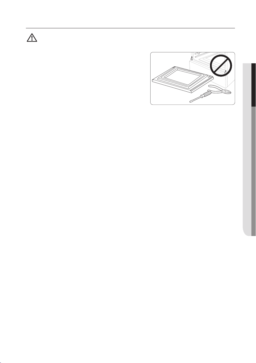
CAUTION : Please DO NOT push the
unit strongly when you install. These actions can cause the damage to the unit.
Please DO NOT grasp the knob
and push when you install.
(Grasp the L/R door area to push
the unit.)
CAUTION
CAUTION
Do NOT lift or handle the unit by the cooktop frame.
C2
C1
Fig. 1
C4
C3
1. The counter top around the cut-out should be flat and leveled (see hatched
area on Fig. 1).
2. Before installing the unit, measure the heights of the two cabinet sides
(C1~C4), front and back (See Fig. 1) from the floor to the top of the counter.
3. Level the range using the four leveling legs so that the height from the floor
to the underside of the cooktop frame is greater than the tallest cabinet
measurement by at least 1/16".
4. Slide the unit into the cabinet (DO NOT PUSH THE UNIT HARD). Make
sure the center of the unit aligns with the center of the cabinet cut-out.
English - 21
Page 22
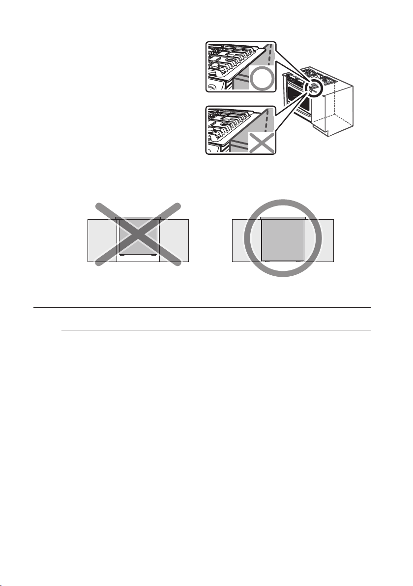
5. The metal flange under each side of
the cooktop MUST be placed over
the cabinet countertop for proper
unit support. The cooktop should
NOT rest directly on the countertop
or else it could cause damage to
the cooktop voiding the warranty.
Level the unit if needed.
IMPORTANT: MAKE SURE the unit is supported by the leveling legs and NOT by
the cooktop itself.
GAS REQUIREMENTS
Provide adequate gas supply
This range is designed to operate at a pressure of 5 in (13 cm) of water column
on natural gas or 10 in (25 cm) of water column on LP gas (propane or butane).
Make sure you are supplying your range with the type of gas for which it is designed.
Do not attempt to convert the appliance from the gas specified in this manual
to a dierent gas without consulting the gas supplier.
This range is convertible for use on natural or propane gas. If you decide to use this
range on LP gas, conversion must be made by a qualified LP installer before attempting
to operate the range.
For proper operation, the pressure of natural gas supplied to the regulator must be
between 5 in and 13 in (13 cm and 33 cm) of water column.
For LP gas, the pressure supplied must be between 10 in and 13 in (25 cm and 33 cm)
of water column.
When checking for proper operation of the regulator, the inlet pressure must be at least
1 in (2.5 cm) greater than the operating (manifold) pressure as given.
The pressure regulator located at the inlet of the range manifold must remain in the
supply line regardless of whether natural or LP gas is being used.
A flexible-metal appliance connector used to connect the range to the gas supply
line should have an I.D. of 0.5 in (1.3 cm) and be 5 ft (152 cm) in length for ease of
installation. In Canada, flexible connectors must be single-wall metal connectors no
longer than 6 ft (183 cm) in length.
Do not kink or damage the flexible metal tubing when moving the range.
English - 22
Page 23
SPECIAL GAS REQUIREMENTS (GAS MODELS SOLD IN MASSACHUSSETTS)
COMMONWEALTH OF MASSACHUSETTS REQUIREMENTS:
Gas leaks may occur in your system, creating a dangerous situation.
WARNING
– Gas leaks may not be detected by smell alone.
– Gas suppliers recommend you purchase and install a UL-approved
gas detector. Gas detector should be installed in accordance with the
manufacturers instructions.
• Range must be installed by a qualified plumber or gas fitter by the State of
Massachusetts.
• A T-handle manual gas valve MUST be installed in the gas supply line to your
range.
• If a flexible gas connector is used to install your range, multiple flexible gas lines
must not be connected in series.
ELECTRICAL REQUIREMENTS
To reduce the risk of fire, electric shock, or personal injury:
WARNING
All ranges
• Do not use an extension cord or adapter plug with this range.
• This range must be properly grounded.
• Check with a qualified electrician if you are in doubt as to whether your range
is properly grounded.
• Do not modify the plug provided with your range—if it doesn’t fit the outlet,
have a proper outlet installed by a qualified electrician.
• All wiring and grounding must be done in accordance with local codes or, in
the absence of local codes, with the National Electrical Code, ANSI/NFPA No.
70 – Latest Revision (for the U.S.) or the Canadian Electrical Code CSA C22.1
– Latest Revisions and local codes and ordinances.
• Wiring diagram is located on the back of the range. (Inside of the cover back
wire)
• This range is equipped with an electronic ignition system that will not operate
if plugged into an outlet that is not properly polarized.
03 INSTALLATION REQUIREMENTS
English - 23
Page 24
Gas models
• All gas models are equipped with a power cord with an equipment-grounding
conductor and a grounding plug.
• A 120-Volt, 60-Hz, AC, approved electrical service with a 20-amp circuit
breaker or time-delay fuse is required for all U.S. and Canadian models.
• Check for ¾-in (1.9-cm) UL-listed strain relief where the power cord comes
out of the range cabinet.
• Do not reuse a power supply cord from an old range or other appliance.
• The power cord electric supply wiring must be retained at the range cabinet
with a suitable UL-listed strain relief.
• A time-delay fuse or circuit breaker is also recommended.
Grounding
• All ranges must be grounded for personal safety.
• All gas models have a power cord with an equipment-
grounding conductor and a grounding plug.
• The plug must be firmly plugged into a three-prong outlet
that is properly installed and grounded in accordance with
all local codes and ordinances. In the event of a malfunction
or breakdown, grounding will decrease the risk of electrical
shock by providing a path for the electric current.
• Do not use a damaged power plug or loose wall outlet.
• Do not use an extension cord or adapter with this appliance.
• Do not, under any circumstances, cut, modify, remove, or otherwise defeat
the grounding (third) prong from the power cord. If the plug and the outlet
do not match or you have any doubt, have a qualified electrician install the
proper outlet.
The customer should have the wall receptacle and circuit checked by a
qualified electrician to make sure the receptacle is properly grounded.
Ground Fault Circuit Interrupters(GFCIs) are not required or recommended for
gas range receptacles.
• NEVER connect ground wire to plastic plumbing lines, gas lines, or water
pipes.
Failure to follow these instructions can result in death, fire, or electrical
shock.
CAUTION
Ensure proper
ground
and firm
connection
before use.
English - 24
Page 25
Usage situations where appliance power cord will be
disconnected frequently
Do not use an adapter plug in these situations because disconnecting of the
power cord places undue strain on the adapter and leads to eventual failure
of the adapter ground terminal. Where a standard two-prong wall receptacle
is encountered, it is the personal responsibility and obligation of the customer
to have it replaced with a three-prong (grounding) receptacle by a qualified
electrician before using the appliance.
Additional installation requirements for mobile homes
The installation of appliances designed for mobile home installation must conform
with the Manufactured Home Construction and Safety Standard, Title 24 CFR,
Part 3280 (formerly the Federal Standard for Mobile Home Construction and
Safety, Title 24, HUD, Part 280) or, when such standard is not applicable, the
Standard for Manufactured Home Installations, latest edition (Manufactured
Home Sites, Communities and Set-Ups), ANSI A225.1, latest edition, or with
local codes. In Canada, mobile home installation must be in accordance with the
current CAN/CSA Z240/MH Mobile Home Installation Code.
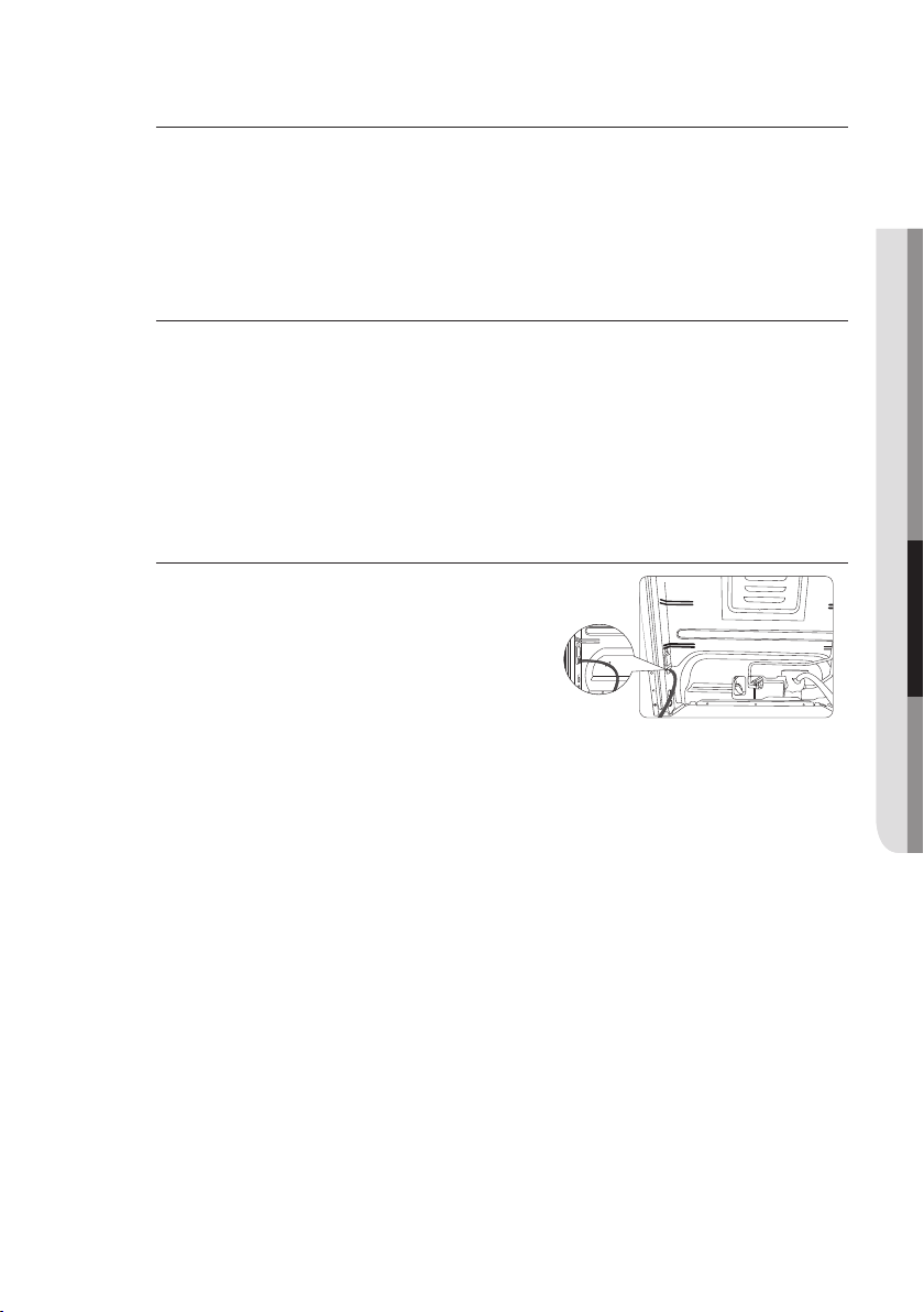
Power cord location
The power cord for this appliance is located
on the back of the range, near the bottom right
hand corner. The 53-in (135-cm) power cord
will come installed on the range and taped to
the back for shipping.
03 INSTALLATION REQUIREMENTS
English - 25
Power cord location
Page 26
tools and materials
WHAT’S IN THE BOX
Parts supplied
Surface burners and caps (5) Surface burner grates (3) Anti-tip bracket kit
Griddle (1), Wok grate (1),
Filler Kit (1) & Screws (3),
Temp probe (1), Wire Rack (2)
• Make sure you have received all of the supplied parts shown above.
• If your range was damaged during shipping or you do not have all of the
supplied parts, contact your local retailer.
Parts needed
*NX58H9950W* only
*NX58H9500W*,
NX58K9500W* only
Gas line
shut-o
valve
Flexible metal
appliance connector
½ in (ID) x 5 ft
Tools needed
Flat-blade
screwdriver
Pencil and
ruler
Flare union
adapter ¾ in or
½ in (NPT) x ½
in (ID)
Phillips
screwdriver
Level Pipe joint compound Utility knife
Open-end or adjustable
wrench
Flare union
adapter ½
in (NPT) x ½
in (ID)
Pipe wrench (2) Nut driver
English - 26
135-degree
elbow
(optional)
Lag bolt or
½-in (OD)
sleeve anchor
Soapy water
solution
Page 27
installation instructions
INSTALLING YOUR GAS RANGE
IMPORTANT: Please read the following instructions, as well as the Important Safety
Instructions section at the front of this manual, completely and carefully BEFORE
installing and/or operating the gas range. Improper installation, adjustment, service, or
maintenance can cause personal injury or property damage.
To order parts or accessories, contact your
local retailer or refer to the last page.
To ensure proper installation, we strongly
recommend that you hire a professional
installer.
Step 1. Unpack the range
Remove all packaging materials. Failure to remove packaging materials could
result in damage to the appliance.
Inventory all loose parts against the Parts supplied components listed on page 26.
Check for shipping damage and/or missing parts. Any damage and/or missing
parts should be reported to your local retailer.
Step 2. Connect the range to gas supply
04 TOOLS AND MATERIALS & INSTALLATION INSTRUCTIONS
Shut o the main gas supply valve before disconnecting the old range and
leave it o until the new hookup has been completed. Don’t forget to relight
the pilot on other gas appliances when you turn the gas back on.
Because hard piping restricts movement of the range, the use of a CSA
International-certified flexible metal appliance connector is recommended unless
local codes require a hard-piped connection.
English - 27
Page 28
If the information in this manual is not followed exactly, a fire or explosion
may result, causing death, personal injury, or property damage.
WARNING
– Do not store or use gasoline or other flammable vapors and liquids in the
vicinity of this or any other appliance.
– WHAT TO DO IF YOU SMELL GAS:
• DO NOT light a match, candle, or cigarette.
• DO NOT try to light any appliance.
• DO NOT touch any electrical switch.
• DO NOT use any phone in your building.
• Clear the room, building, or area of all occupants.
• Immediately call your gas supplier from a neighbor’s phone. Follow the
gas supplier’s instructions.
• If you cannot reach your gas supplier, call the fire department.
– Installation and service must be performed by a qualified installer, service
agency, or gas supplier.
Never use an old connector when installing a new range. If the hard-piping
method is used, you must carefully align the pipe; the range cannot be moved
after the connection is made.
To prevent gas leaks, apply pipe-joint compound or wrap pipe-thread tape with
Teflon on all male (external) pipe threads.
1. Install a manual gas line shut-o valve in the gas line in an easily accessed
location outside of the range.
Make sure everyone operating the range knows where and how to shut o
the gas supply to the range.
2. Install male 0.5-in (1.3-mm) flare union adapter to the 0.5-in (1.3-mm) NPT
internal thread at the regulator inlet. Use a backup wrench on the regulator
fitting to avoid damage.
When installing the range from the front, remove the 90 ° elbow for easier
installation.
3. Install male 0.5-in (1.3-mm) or 0.75-in (1.9-mm) flare union adapter to the
NPT internal thread of the manual shut-o valve, taking care to back up the
shut-o valve to keep it from turning.
4. Connect flexible metal appliance connector to the adapter on the range.
Position range to permit connection at the shut-o valve.
5. When all connections have been made, make sure all range controls are
in the o position and turn on the main gas supply valve. Use a liquid leak
detector at all joints and connections to check for leaks in the system.
Do not use a flame to check for gas leaks to prevent death, personal injury,
explosion, and/or fire hazard.
WARNING
When using test pressures greater than 1/2 psig to pressure-test the gas supply
system of the residence, disconnect the range and individual shut-o valve from
the gas supply piping. When using test pressures of 1/2 psig or less to test
the gas supply system, simply isolate the range from the gas supply system by
closing the individual shut-o valve.
English - 28
Page 29
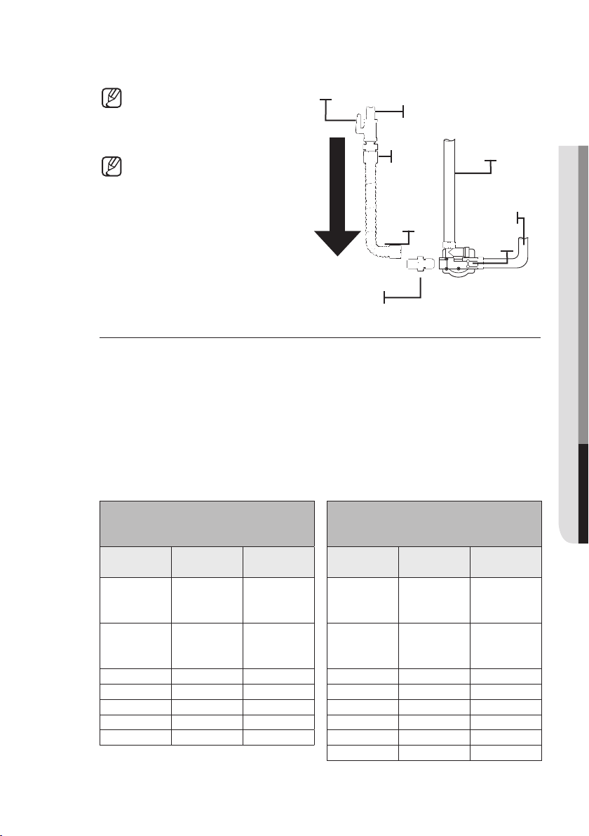
Flexible connector hookup
Installer: Inform the consumer of the location of the gas shut-o valve.
If your area requires a rigid pipe
hookup, contact a qualified
installer, service agency, or gas
supplier.
The gas shut-o valve should
be installed in an accessible
location in the gas piping,
external to the appliance, for the
purpose of turning on or shutting
o the gas to the appliance.
Gas Shut-O Valve
Flex Connector
(6-ft max.)
Gas Flow into Range
Adapter
0.5-in or 0.75-in Gas Pipe
Tubing Line to
Oven Burner
Adapter
Control Valve
Tubing Line
to Cooktop
Control
Manifold
Pressure
Regulator
Step 3. Convert to lp gas (optional)
All new gas ranges are shipped from the factory set up to use natural gas. Any
Samsung gas range can be converted to use LP gas. Refer to page 72 in the
User Manual to contact a qualified service technician.
The conversion process should only be performed by a qualified LP gas installer.
Conversion instructions and LP orifices will be supplied with the LP conversion
kit. The conversion to LP requires all burner orifices to be changed (5 surface
burners and 2 oven burners).
In addition, the nozzle on the gas pressure regulator needs to be reversed. All
replaced orifices must be left with the consumer, including the instructions and
retrofit sizes and orifice indication.
BURNER ORIFICE SIZES AND
OUTPUT RATINGS
(LP Gas [Propane] 10 in WCP)
Burner
Location
BTU Rate
Orifice Size
[mm]
In: 0.46/
RF 14,500
Out: 0.74
(2pcs)
LF 11,500 1.04 RF² 18,000
RR 4,000 0.62 LF 15,000 1.78
LR 7,500 0.83 RR 5,000 1.01
CTR 7,500 0.83 LR 9,500 1.40
BAKE 15,000 1.15 CTR 9,500 1.38
BROIL 11,500 1.02 BAKE 18,000 1.90
¹Model NX58H9950W* ²Model NX58H9500W*, NX58K9500W*
BURNER ORIFICE SIZES AND
OUTPUT RATINGS
(Natural Gas 5 in WCP)
Burner
location
BTU Rate
Orifice size
[mm]
In: 0.70/
RF¹ 19,000
Out: 1.30
(2pcs)
In: 0.70/
Out: 1.30
(2pcs)
BROIL 16,500 1.80
04 TOOLS AND MATERIALS & INSTALLATION INSTRUCTIONS
English - 29
Page 30
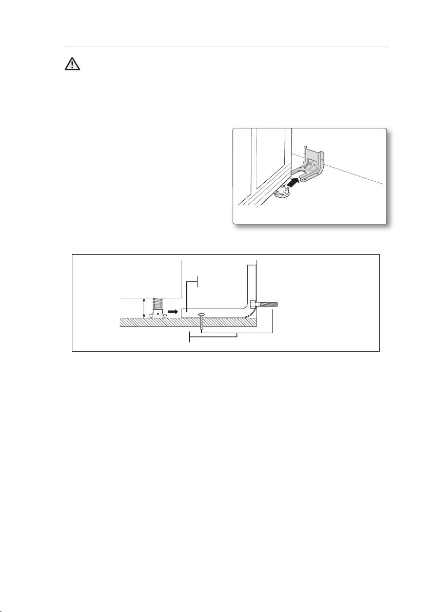
Step 4. Install the anti-tip device
Anti-Tip
bracket
Screw must enter
wood or concrete
*approximately
21/32” (16.5 mm)
*NOTE: To install
the Anti-Tip bracket,
release the leveling leg.
A minimum clearance
of 21/32” (16.5 mm) is
required between the
range bottom and the
kitchen floor.
To reduce the risk of tipping, the appliance must be secured by properly
installing the anti-tip device packed with the appliance.
WARNING
• All ranges can tip, resulting in personal injury.
• Tipping ranges can cause burns from spills, personal injury, and/or death.
• To prevent accidental tipping, install and check the anti-tip bracket
following the instructions and template supplied with the bracket.
An anti-tip bracket and screws,
installation instructions, and template
are shipped with every range (PN
DG94-00870B). The instructions include
information necessary to complete the
installation of the anti-tip bracket. Read
and follow the instructions on the sheet
and use the template for anti-tip bracket
installation. If not properly installed, the
range could be tipped by you or a child
standing, sitting, or leaning on an open oven door.
To check if the bracket is installed and engaged properly, remove the warming
drawer or storage drawer and look underneath the range to see that the leveling
leg is engaged in the bracket. Carefully tip the range forward. The bracket should
stop the range within 4 inches (10.2 cm) of tipping. If it does not, the bracket
must be reinstalled.
If the range is pulled from the wall for any reason, always repeat this procedure
to verify the range is properly secured by the anti-tip bracket. Never completely
remove the leveling legs or the range will not be secured to the anti-tip device
properly.
English - 30
Page 31

Step 5. Plug in and place
BEFORE OPERATING OR TESTING, follow the grounding
requirements on pages 23 ~ 24 in this manual. Improper connection
WARNING
of the grounding plug can result in a risk of electric shock.
• All gas ranges come with a power cord. The power cord
is connected to the rear of the range. Please review "Electrical
requirements" on pages 23 ~ 24.
• All U.S. and Canadian models are produced with a 3-wire, 120-volt,
60-Hertz electrical system. The entire system, including the power cord,
is preinstalled and prewired at the factory. Altering any part of this system
may result in a short or overload.
1. Plug in the power cord. Make sure the outlet
meets local or national electrical codes as
referenced on pages 23 ~ 24.
2. Slide the range into place.
3. Check the gas supply line to make sure it did
not get damaged and it stayed connected
during positioning.
4. Check to make sure the back leg of the range has slid into the anti-tip
bracket. Carefully tip the range forward to ensure that the anti-tip bracket
engages the back brace and prevents tip-over.
Gas Range Plug
04 TOOLS AND MATERIALS & INSTALLATION INSTRUCTIONS
English - 31
Page 32

Step 6. Level the range
1. Make sure the range is positioned
where you want it.
2. Using a wrench, level the range by
turning the front leveling legs in or
out as necessary. Counterclockwise
shortens the leg and lowers the
range. Clockwise lengthens the leg
and raises the range.
Adjusting the two front legs is usually sucient, but all four legs adjust if
necessary.
Adjust the leveling legs only as far as necessary to level the range. Extending
the leveling legs more than necessary or removing legs can cause the range
to be unstable.
3. If range is next to or between
cabinets, make sure the cooktop
(without the surface burner grates) is
level with the countertops.
4. Position an oven rack in the center
rack position.
5. Check the level of the range with
a carpenter level using the two
positions shown at right.
6. After the range becomes level, slide
the range away from the wall so that
the anti-tip bracket can be installed.
Leveling leg
English - 32
Page 33

Step 7. Assemble the surface burners
Do not operate the surface burners without all burner parts in place.
CAUTION
1. Position surface burner heads on top of the surface burner manifolds as
shown at right. The electrodes will fit into the slot in the bottom of the heads.
Make sure the surface burner heads are flat and parallel with the cooktop.
2. Place the matching size caps on top of each surface burner head.
The caps on Precise simmer burner (RR) and inside Dual Burner (RF) can be
interchangeably used.
Top Bottom
3. Place the left, center, and right
surface burner grates on the
cooktop. The edges of the grates
should match up with the edges of
the cooktop.
04 TOOLS AND MATERIALS & INSTALLATION INSTRUCTIONS
Step 8. Check the ignition of surface burners and oven burners
Check the operation of all cooktop and oven burners after the range has been
installed and assembled, gas supply lines have been carefully checked for leaks,
and electrical power cord has been plugged in.
All surface and oven burners have electronic ignition.
To turn on a surface burner:
1. Ignite the surface burner
English - 33
Page 34

To start the bake burners:
2
3
4
1
1
2
3
1. Press the Bake or Roast or Bake button.
2. If necessary, use the number pad to change the default temperature (350 °F)
to between 175 °F and 550 °F.
3. Press the START/SET button.
• The gas oven preheats until it reaches the preheat temperature of 350 °F.
• When the preheat is complete, place the food in the gas oven, and close
the door.
4. When the cooking is complete, press the OFF/CLEAR button, and take out
the food.
To change the temperature during cooking, repeat steps 1 through 3 above.
To start the broil burners:
Broiling uses an upper gas oven alone to brown food. Meat or fish must be put
on a broiling grid in a broiling pan.
1. Press the Broil button once for the high temperature, or twice for low.
2. Press the START/SET button to start cooking.
3. When broiling on either side is complete, press the OFF/CLEAR button.
English - 34
Page 35

Checking the flame quality:
All combustion flames need to be visually checked to determine their flame
quality.
1. Soft blue flames—Normal for natural gas operation.
2. Yellow tips on outer cones—Normal for LP gas
operation.
3. Yellow flames—Abnormal for any gas operation; call
for service.
If burner flame looks like 3, the range should
not be used until it is serviced. Call for
service. Normal burner flames shall look like 1 1
or 2, depending on the gas type you use.
Step 9. Final installation checklist
You have just completed installing your range. Make sure all controls are in the o
position and the flow of ventilation air to the range is unobstructed. The following
is a checklist to confirm your range is safely installed and ready for operation.
- Gas line has been properly connected to the range.
The gas has been turned on. All connections have been
checked for leaks.
- Range is plugged into the properly grounded electrical
receptacle.
Gas Range
Plug
04 TOOLS AND MATERIALS & INSTALLATION INSTRUCTIONS
- Approved anti-tip bracket is properly installed
and engaged with the range.
- Range is leveled and is firmly sitting on a solid,
level floor.
- Gas surface burners have been properly
assembled.
- All burners have been tested for proper
operation.
- FOR INSTALLER ONLY—Check and/or adjust the broil and oven burner
flames as described in this manual.
Locking screw
English - 35
Page 36

ADJUSTING THE OVEN BURNER AIR ADJUSTMENT SHUTTERS
All oven burners have an air adjustment
shutter. The purpose of the shutter is
to regulate the flow of air to the flames.
Properly adjusted flames should burn
steadily with approximately 1-in of blue
cone. The flames should never extend
past the edge of the burner baes. Even
though these are preset at the factory, they
should be checked and, if needed, adjusted
periodically to ensure ecient operation.
To check and adjust the oven burner air adjustment
shutters:
1. Open the oven door.
2. Remove the oven racks.
3. Remove the oven floor.
4. Press the Bake button, then the START/SET.
5. After the oven has lit, visually check the flames coming out of the upper and
lower burners. If adjustment is needed, carefully adjust the air adjustment
shutters.
The shutters are located at the base of the burner manifolds near the back oven
wall.
Air
adjustment
shutter
Air
adjustment
shutter
To adjust the shutter, loosen the locking screw
and rotate the shutter towards the open or closed
position as needed. If flames are lifting o the burner
ports, gradually reduce the air shutter opening until
the flames are stabilized.
If flames are too yellow and/or too large, gradually
Locking screw
increase the air shutter opening until the flames have
approximately a 1-in blue cone.
If the range is set up for natural gas, the flames should burn with no yellow
tipping. If the range is set up for LP gas, small yellow tips at the end of the
cones are normal.
After the flames are adjusted properly, shut o the
oven, retighten the locking screws, replace the oven
bottom and racks, and close the oven door.
Locking screw
English - 36
Page 37

To adjust flame low setting
Identify which burner is exhibiting too high or too low of simmer rate via manifold
panel graphics.
1. Rotate a knob to "LO" position and remove the knob
from the valve stem while the flame is lit.
Simmer Set
Screw
04 TOOLS AND MATERIALS & INSTALLATION INSTRUCTIONS
2. Carefully push the screw driver into the C channel of
the valve, until it hits the simmer set screw. Make sure
Small Screwdriver
the screwdriver flathead is seated into the set screw
groove.
Valve Stem
3. Rotate valve set screw clockwise to decrease "LO" setting flame output, or
rotate set screw counter clockwise to increase "LO" setting flame output.
English - 37
Page 38

memo
Page 39

memo
Page 40

QUESTIONS OR COMMENTS?
COUNTRY CALL OR VISIT US ONLINE AT
U.S.A
Consumer
Electronics
CANADA 1-800-SAMSUNG (726-7864)
1-800-SAMSUNG (726-7864) www.samsung.com/us/support
www.samsung.com/ca/support (English)
www.samsung.com/ca_fr/support (French)
DG68-00555A-05
Page 41

NX58H9500W*
NX58H9950W*
NX58K9500W*
Estufa de gas
deslizable
manual de instalación
imagine las posibilidades
Gracias por adquirir este producto Samsung.
Page 42

ADVERTENCIA: Si no se sigue la información de este
manual con exactitud, podrían producirse incendios o
explosiones causantes de daños a la propiedad, lesiones
personales o muerte.
• NO debe almacenarse ni utilizarse gasolina u otros líquidos
y vapores inflamables cerca de este u otros artefactos.
• QUÉ HACER SI HAY OLOR A GAS:
- NO intente encender ningún artefacto.
- NO toque ningún interruptor eléctrico.
- NO utilice ningún teléfono dentro del edificio.
- Llame inmediatamente al proveedor de gas desde
el teléfono de un vecino. Siga las instrucciones del
proveedor de gas.
- Si no puede comunicarse con el proveedor de gas, llame
al departamento de bomberos.
• La instalación y el servicio técnico deben ser realizados por
un instalador calificado, agencias de servicio técnico o el
proveedor de gas.
DISPOSITIVO ANTI INCLINACIÓN
ADVERTENCIA
TODAS LAS ESTUFAS PUEDEN INCLINARSE, LO
QUE PUEDE TENER COMO RESULTADO LESIONES
PERSONAES.
LAS ESTUFAS INCLINADAS PUEDEN CAUSAR
QUEMADURAS POR DERRAMES, LESIONES
PERSONALES O LA MUERTE.
INSTALE Y VERIFIQUE LA MÉNSULA ANTI
INCLINACIÓN SEGÚN LAS INSTRUCCIONES Y LA
PLANTILLA PROVISTA CON LA MÉNSULA
Español - 2
.
Page 43

• Para evitar que se incline la estufa, fije al piso un
dispositivo anti inclinación aprobado. (Consulte Instalación
del dispositivo anti inclinación en las Instrucciones de
instalación.) Incline cuidadosamente la estufa hacia
adelante para verificar que la instalación se haya realizado
correctamente. El dispositivo anti inclinación debe
conectarse y evitar que la estufa se incline.
• Si por alguna razón se separa la estufa de la pared,
asegúrese de que vuelva a conectarse el dispositivo anti
inclinación luego de volver a colocar la estufa en su lugar.
• Siga las instrucciones de instalación que se encuentran en el
Manual de instalación. No seguir estas instrucciones puede
ocasionar muerte, lesiones personales graves o daños a la
propiedad.
• NO se pare / siente / apoye sobre la puerta ni el cajón
para evitar la inclinación accidental de la estufa.
Español - 3
Page 44

contenido
ANTES DE COMENZAR
6
INFORMACIÓN IMPORTANTE DE
SEGURIDAD
7
6 Acerca de este manual
7 Lea todas las instrucciones antes de usar
este artefacto
7 Símbolos usados en este manual
7 Advertencia sobre la State of California
Proposition 65 (solo EE.UU.)
7 Mancomunidad de Massachusetts
8 Seguridad general
9 Seguridad contra incendios
9 Seguridad del gas
10 Seguridad de la electricidad y la conexión a
tierra
11 Seguridad de la instalación
12 Seguridad de la ubicación
12 Seguridad de la cubierta
14 Seguridad del horno
15 Seguridad del cajón inferior/cajón de
calentamiento
15 Seguridad durante la auto-limpieza del horno
COMPONENTES DE LA ESTUFA A GAS
16
Español - 4
16 Descripción general
17 Especificaciones de la estufa de gas
Page 45

REQUISITOS DE INSTALACIÓN
18
18 Requisitos de ubicación
20 Kit de relleno trasero opcional
21 Para evitar la rotura
22 Requisitos para el gas
23 Requisitos especiales para el gas
(modelos de gas vendidos en Massachusetts)
23 Requisitos eléctricos
HERRAMIENTAS Y MATERIALES
26
INSTRUCCIONES DE INSTALACIÓN
27
26 Contenido de la caja
27 Instalación de la estufa de gas
27 Paso 1. Desembalaje de la estufa
27 Paso 2. Conexión de la estufa al suministro
de gas
29 Paso 3. Conversión a gas LP (opcional)
30 Paso 4. Instalación del dispositivo anti
inclinación
31 Paso 5. Enchufe y ubicación
32 Paso 6. Nivelación de la estufa
33 Paso 7. Montaje de los quemadores
superiores
33 Paso 8. Verificación del encendido de
los quemadores superiores y los
quemadores del horno
35 Paso 9. Lista de verificación final de la
instalación
36 Ajuste de los obturadores de ajuste del aire
de los quemadores del horno
Español - 5
Page 46

antes de comenzar
ACERCA DE ESTE MANUAL
LEA ESTAS INSTRUCCIONES EN SU TOTALIDAD Y CUIDADOSAMENTE.
Nota importante para el instalador
• Lea todas las instrucciones contenidas en este manual antes de instalar la
estufa.
• Retire todos los materiales de empaque de los compartimientos del horno
antes de conectar la alimentación eléctrica y el suministro de gas a la estufa.
• Cumpla todos los códigos y ordenanzas exigidos por las autoridades
pertinentes.
• Asegúrese de dejar estas instrucciones con el usuario final.
• La instalación de este artefacto requiere conocimientos mecánicos básicos.
• La instalación adecuada es responsabilidad del instalador.
• La falla del producto debido a una instalación inadecuada no está cubierta
por la Garantía.
Nota importante para el usuario final
Conserve estas instrucciones con el manual del usuario para consultas futuras.
• Como con cualquier electrodoméstico que genera calor, existen ciertas
precauciones de seguridad que se deben cumplir.
• Asegúrese de que su electrodoméstico sea correctamente instalado y
conectado a tierra por un técnico calificado.
• Asegúrese de que los revestimientos de las paredes alrededor de la estufa
pueden soportar el calor que ésta genera.
• Los gabinetes de almacenamiento deben colocarse un mínimo de
30pulgadas (76.2 cm) por encima de la superficie de los quemadores.
Nota importante para el servicio técnico
El diagrama eléctrico se encuentra en un sobre fijado a la parte trasera de la
estufa.
Español - 6
Page 47

información importante de seguridad
LEA TODAS LAS INSTRUCCIONES ANTES DE USAR ESTE ARTEFACTO
• Todos los equipos eléctricos y de gas con piezas móviles pueden ser peligrosos.
Lea las instrucciones de seguridad importantes para este artefacto incluidas en este
manual. Las instrucciones deben seguirse para minimizar el riesgo de lesión, muerte
o daño a la propiedad.
• Guarde este manual. No lo deseche.
SÍMBOLOS USADOS EN ESTE MANUAL
ADVERTENCIA: Prácticas peligrosas o inseguras que pueden provocar
lesiones graves o la muerte.
PRECAUCIÓN: Prácticas peligrosas o inseguras que pueden provocar
descargas eléctricas, lesiones personales o daños a la propiedad.
NOTA: Instrucciones y sugerencias útiles
Estos iconos y símbolos de advertencia se incluyen para evitar que usted u otras
personas sufran lesiones. Sígalos explícitamente. Una vez que haya leído esta sección,
consérvela en un lugar seguro para consultas futuras.
01 ANTES DE COMENZAR E INFORMACIÓN IMPORTANTE DE SEGURIDAD
ADVERTENCIA SOBRE LA STATE OF CALIFORNIA PROPOSITION 65 (SOLO EE.UU.)
• ADVERTENCIA : Este producto contiene productos químicos reconocidos en el estado de
California como capaces de provocar cáncer y defectos de nacimiento u otras afecciones
reproductivas.
• Los aparatos a gas pueden causar un bajo nivel de exposición a las sustancias indicadas en
la Proposición 65, incluyendo, entre otros, benceno, monóxido de carbono, formaldehído y
hollín, sustancias resultantes de una combustión incompleta del gas natural o del LP.
MANCOMUNIDAD DE MASSACHUSETTS
• Este producto debe ser instalado por un plomero con licencia o un gasista matriculado o
con licencia del Estado de Massachusetts. Cuando se utilicen válvulas de bola para el cierre
del gas, se debe usar una manija en forma de "T". No deben conectarse varios conductos
flexibles de gas en serie.
Español - 7
Page 48

SEGURIDAD GENERAL
ADVERTENCIA Para reducir el riesgo de incendio, descarga eléctrica, lesiones
personales y/o muerte, obedezca las siguientes precauciones.
• No toque ninguna parte de la estufa, incluyendo,
entre otros, los quemadores del horno, los
quemadores superiores o las partes internas durante
la cocción o inmediatamente después de cocinar.
• Debe conocer la ubicación de la válvula de cierre
del gas y cómo cerrarla si es necesario.
• Asegúrese de que el dispositivo anti inclinación
esté correctamente instalado en la estufa. Consulte
las instrucciones de instalación para obtener más información.
• No permita que los niños se acerquen a la estufa ni que se metan o se paren sobre ella.
No permita que los niños jueguen con la estufa ni con ninguna parte de la estufa. Los niños
no deben quedar sin vigilancia en el lugar donde se utiliza la estufa. Para la seguridad de los
niños, recomendamos utilizar la función de control/bloqueo de la puerta.
• Quite todos los materiales de empaque de la estufa antes de utilizarla para evitar que se
prendan fuego. Mantenga todos los materiales de empaque fuera del alcance de los niños.
Deseche adecuadamente los materiales de empaque luego de desembalar la estufa.
• No guarde ningún objeto que resulte de interés para los niños sobre la cubierta o el protector
posterior de la estufa. Los niños que se trepen a la estufa para alcanzar un objeto podrían
morir o resultar seriamente lesionados.
• No opere la estufa si esta o alguna de sus partes se encuentra dañada, no funciona
correctamente o si falta alguna pieza.
• No utilice la estufa como calefactor del ambiente. Esta estufa se debe usar exclusivamente
para cocinar.
• No utilice limpiadores para horno ni revestimientos de horno dentro o cerca de ninguna parte
del horno.
• Utilice únicamente agarradores aislantes secos.
• No utilice la estufa para calentar recipientes cerrados con alimentos.
• No golpee el vidrio del horno.
• Al desechar la estufa, corte el cable de alimentación y quite la puerta.
• Desenchufe o desconecte la alimentación antes de realizar tareas de mantenimiento o
reparación.
• Asegúrese de que todas las carnes de res y de ave se cocinen bien. La carne de res debe
cocinarse siempre a una temperatura interna de 160 °F (71 °C). La carne de ave debe
cocinarse siempre a una temperatura interna de 180 °F (82 °C).
Español - 8
Page 49

SEGURIDAD CONTRA INCENDIOS
ADVERTENCIA Para reducir el riesgo de incendio, descarga eléctrica, lesiones
personales y/o muerte, obedezca las siguientes precauciones.
• No guarde, coloque ni use materiales inflamables
o combustibles como papel, plástico, agarradores
aislantes, ropa de cama, cortinas, gasolina u otros
vapores o líquidos inflamables cerca de la estufa.
• No lleve prendas amplias o colgantes mientras
utiliza la estufa.
• Para evitar la acumulación de grasa,
limpie regularmente las ventilaciones.
• No permita que los agarradores aislantes u otros materiales inflamables entren en contacto con
el elemento calentador. No utilice una toalla u otras telas voluminosas como agarrador aislante.
• No use agua para apagar un fuego provocado por la grasa. Para extinguir el fuego de la
materia grasa, apague la fuente de calor y extinga el fuego con una tapa que ajuste bien o
utilice un extinguidor de incendios de polvo químico seco o de espuma para usos diversos.
• Si la grasa llegara a encenderse dentro del horno, apague el horno presionando el botón
OFF/CLEAR (APAGAR/BORRAR).
Mantenga cerrada la puerta del horno hasta que se extinga el fuego.
De ser necesario, utilice un extinguidor de incendios de polvo químico seco o de espuma
para usos diversos.
• No caliente recipientes cerrados con alimentos. La acumulación de presión puede causar
que el recipiente explote y provocar lesiones.
01 ANTES DE COMENZAR E INFORMACIÓN IMPORTANTE DE SEGURIDAD
SEGURIDAD DEL GAS
ADVERTENCIA Para reducir el riesgo de incendio, descarga eléctrica, lesiones
personales y/o muerte, obedezca las siguientes precauciones.
Si hay olor a gas:
• Cierre la válvula y no use la estufa.
• No encienda cerillos, velas ni cigarrillos.
• No encienda ningún artefacto eléctrico o a gas.
• No toque ningún interruptor eléctrico ni enchufe el
cable de alimentación en un tomacorriente.
• No utilice ningún teléfono dentro del edificio.
• Evacue a todos los ocupantes del ambiente, edificio
o área.
• Llame inmediatamente al proveedor de gas desde el teléfono de un vecino.
Siga las instrucciones del proveedor de gas.
• Si no puede comunicarse con el proveedor de gas, llame al departamento de bomberos.
Español - 9
Page 50

Vericación de pérdidas de gas
• La prueba de pérdidas del artefacto debe ser realizada de acuerdo con las instrucciones del
fabricante. No utilice una llama para verificar si hay pérdidas de gas. Utilice un cepillo para
esparcir una mezcla de agua jabonosa alrededor del área que está verificando. Si hay una
pérdida de gas, verá pequeñas burbujas en la mezcla de agua jabonosa en el punto de la
pérdida.
SEGURIDAD DE LA ELECTRICIDAD Y LA CONEXIÓN A TIERRA
ADVERTENCIA Para reducir el riesgo de incendio, descarga eléctrica, lesiones
personales y/o muerte, obedezca las siguientes precauciones.
• Enchufe el artefacto a un tomacorriente de 3 clavijas
conectado a tierra.
• No retire la clavija de conexión a tierra.
• No utilice un adaptador ni un cable prolongador.
• No utilice un enchufe o un cable de alimentación
dañado ni un tomacorriente flojo.
• No modifique el enchufe, el cable de alimentación
ni el tomacorriente de ninguna manera.
• No coloque un fusible en el circuito neutral o de conexión a tierra.
• Utilice un circuito eléctrico exclusivo de CA, 120 voltios, 60 Hz, 20 A y equipado con fusibles
para esta estufa. Se recomienda un fusible de retardo o un disyuntor.
No conecte más de un artefacto a este circuito.
• No conecte el cable a tierra a cañerías de plomería de plástico, tuberías de gas o tuberías de
agua caliente.
• Esta estufa debe conectarse a tierra. En el caso de fallas o averías, la conexión a tierra
reducirá el riesgo de sufrir descargas eléctricas, ya que le ofrece una ruta a la corriente
eléctrica. Esta estufa está equipada con un cable que dispone de un enchufe con conexión
a tierra. El enchufe debe enchufarse firmemente en un tomacorriente que esté correctamente
instalado y que disponga de conexión a tierra, de acuerdo con los códigos y ordenanzas
locales. Si no está seguro de si el tomacorriente está conectado correctamente a tierra, debe
verificarlo un electricista matriculado.
• La estufa está equipada con un enchufe de 3 clavijas con conexión a tierra. Este cable debe
enchufarse a un tomacorriente adecuado de 3 clavijas con conexión a tierra, que cumpla con
todos los códigos y las ordenanzas locales. Si los códigos permiten el uso de un conductor a
tierra independiente, recomendamos que un electricista calificado determine la vía adecuada
para este conductor a tierra.
• El servicio eléctrico que alimentará a la estufa debe cumplir con los códigos locales. Además
de los códigos locales, debe cumplir con la versión más reciente de ANSI/NFPA Nro. 70
(para EE.UU.) o con la versión más reciente del Código eléctrico de Canadá CSA C22.1.
• Es responsabilidad personal del propietario de la estufa brindar el servicio eléctrico correcto
para este equipo.
Español - 10
Page 51

SEGURIDAD DE LA INSTALACIÓN
ADVERTENCIA Para reducir el riesgo de incendio, descarga eléctrica, lesiones
personales y/o muerte, obedezca las siguientes precauciones.
• Un instalador calificado debe realizar la instalación
y la conexión a tierra correcta, de acuerdo con las
instrucciones de instalación. Solo instaladores de
estufas de gas calificados o técnicos de servicio
deberían realizar los ajustes y el servicio técnico.
• No intente realizar el servicio, modificar ni
reemplazar ninguna pieza de la estufa a menos que
este manual lo recomiende específicamente.
Todas las demás tareas de servicio técnico deben
ser encomendadas a un técnico calificado.
• Utilice siempre conectores flexibles nuevos cuando instale un artefacto a gas.
No utilice conectores flexibles viejos.
• Asegúrese de que el dispositivo anti inclinación esté correctamente instalado en la estufa.
Consulte las instrucciones de instalación para obtener más información.
• Debido al tamaño y al peso de la estufa, se necesitan dos personas o más para moverla.
• Retire toda la cinta y el material de empaque.
• Retire todos los accesorios de la cubierta, del horno y del cajón inferior.
Las rejillas y los comales son pesados. Tenga cuidado al manipularlos.
• Asegúrese de que no se hayan aflojado piezas durante el transporte.
• Asegúrese de que un técnico de servicio o instalador calificado instale y ajuste correctamente
la estufa según el tipo de gas (natural o LP) que utilizará. Para utilizar gas LP en su estufa,
el instalador debe reemplazar los 5 orificios de los quemadores superiores y los 2 orificios
del horno con el juego de orificios para LP y también debe invertir el adaptador GPR. Estos
ajustes debe realizarlos un técnico de servicio calificado de acuerdo con las instrucciones
del fabricante y con todos los códigos y requisitos de la autoridad pertinente. La agencia
calificada que realice este trabajo asume toda la responsabilidad de la conversión a gas.
• La instalación de esta estufa debe cumplir con los códigos locales o, a falta de ellos, con la
versión más reciente del Código nacional de gas combustible, ANSI Z223.1/NFPA.54. En
Canadá, la instalación debe cumplir con el Código de instalación para gas natural
CAN/CGA-B149.1 actual o con el Código de instalación para propano CAN/CGA-B149.2
actual y con los códigos locales, cuando corresponda. El diseño de esta estufa ha sido
certificado por ETL según la versión más reciente de ANSI Z21.1, y por Canadian Gas
Association (Asociación de Gas de Canadá) según la versión más reciente de CAN/CGA-1.1.
01 ANTES DE COMENZAR E INFORMACIÓN IMPORTANTE DE SEGURIDAD
Español - 11
Page 52

SEGURIDAD DE LA UBICACIÓN
ADVERTENCIA Para reducir el riesgo de incendio, descarga eléctrica, lesiones
personales y/o muerte, obedezca las siguientes precauciones.
• Este horno ha sido diseñado para uso doméstico en
interiores solamente.
No instale la estufa en áreas expuestas al aire libre o el agua.
• No instale la estufa en un lugar que esté expuesto a una
corriente de aire fuerte.
• Seleccione un piso nivelado y sólido que pueda soportar el
peso de la estufa. Los pisos sintéticos, como el linóleo, deben
soportar temperaturas de 180 °F (82 °C) sin encogerse,
deformarse ni decolorarse. No instale la estufa directamente
sobre alfombras interiores para cocinas a menos que se
coloque madera contrachapada de ¼ pulgadas o un aislante
semejante entre la estufa y la alfombra.
• Seleccione una ubicación en la que haya un fácil acceso a un tomacorriente de 3 clavijas con conexión a
tierra.
• Si se coloca la estufa cerca de una ventana, no cuelgue cortinas largas ni persianas de papel en esa ventana.
• Para que la estufa pueda ventilarse correctamente, asegúrese de que las ventilaciones no estén bloqueadas
y de que haya suficiente espacio libre arriba, atrás, a los lados y por debajo de la estufa. Las ventilaciones
permiten la salida de aire necesaria para que la estufa funcione adecuadamente con la combustión correcta.
• Asegúrese de que los revestimientos de las paredes que rodean a la estufa puedan soportar un calor de
hasta 200 °F (93 °C), generado por la estufa.
• Se debe evitar colocar gabinetes de almacenamiento arriba de la superficie de la estufa. Si resulta
necesario colocar gabinetes de almacenamiento arriba de la estufa: deje una separación mínima de
40 pulgadas (102 cm) entre la superficie de cocción y la parte inferior de los gabinetes; o instale una
campana para estufas que sobresalga horizontalmente como mínimo 5 pulgadas (12.7 cm) con respecto
al extremo inferior de los gabinetes.
SEGURIDAD DE LA CUBIERTA
ADVERTENCIA Para reducir el riesgo de incendio, descarga eléctrica, lesiones
personales y/o muerte, obedezca las siguientes precauciones.
• Asegúrese de que todos los quemadores estén apagados
cuando no estén en uso.
• No utilice papel de aluminio para cubrir las rejillas ni
ninguna parte de la cubierta.
• No deje los quemadores sin vigilancia en configuraciones
de calor medio o alto.
• Antes de encender los quemadores, asegúrese de que
todas las tapas estén correctamente instaladas en su lugar
y que todos los quemadores estén nivelados.
Español - 12
Page 53

• Siempre use la posición LITE (Encender) al encender los quemadores y asegúrese de que todos los
quemadores enciendan. Si falla el encendido, gire la perilla en OFF (Apagado) y espere hasta que se
disipe el gas.
• Cuando coloque un quemador a fuego lento, no gire la perilla rápidamente. Asegúrese de que la llama
permanezca encendida.
• No coloque objetos sobre la cubierta, excepto cuando se trate de recipientes y utensilios de cocina.
• Esta cubierta está diseñada para cocinar con un wok o con el accesorio del aro para wok. Si se flambean
alimentos, solo debe hacerse debajo de una campana de ventilación encendida.
• Antes de retirar o cambiar recipientes de cocina, apague los quemadores.
• Retire los alimentos y los recipientes de inmediato después de la cocción.
• Antes de retirar alguna pieza del quemador para realizar la limpieza, asegúrese de que la estufa esté
apagada y completamente fría.
• Después de limpiar el distribuidor del quemador, asegúrese de que esté completamente seco antes de
volver a ensamblarlo.
• Asegúrese de que la marca de encendido en el distribuidor del quemador doble esté colocada junto al
electrodo al ensamblarlo.
• Para evitar el envenenamiento por monóxido de carbono, no vierta agua sobre el hueco de la cubierta
durante la limpieza.
• Seleccione recipientes de cocina diseñados para la cocción encima de la estufa. Seleccione recipientes
lo suficientemente grandes como para cubrir las rejillas de los quemadores. Ajuste las llamas de los
quemadores de modo que no se extiendan más allá de la base de los recipientes.
• Para evitar que los recipientes se decoloren, se deformen o que se produzca un envenenamiento por
monóxido de carbono, no utilice recipientes que superen en exceso el tamaño de la rejilla.
• Asegúrese de que las manijas de los recipientes queden orientadas hacia un lado o hacia la parte
posterior de la cubierta, pero nunca sobre los demás quemadores superiores.
• Aléjese de la estufa durante la cocción mediante fritura.
• Caliente siempre los aceites para freír en forma lenta y vigílelos a medida que se calientan.
Si se fríen alimentos a alta temperatura, vigile cuidadosamente el proceso de cocción. Si se utilizará una
combinación de grasas y aceites durante la fritura, debe mezclarlos antes de calentarlos.
• Utilice un termómetro para freidoras de inmersión cuando sea posible. Esto evita el recalentamiento de la
freidora más allá del punto de generación de humo.
• Utilice una cantidad mínima de aceite durante las frituras de inmersión. Evite cocinar alimentos no
descongelados o con excesiva cantidad de hielo.
• Antes de transportar recipientes llenos de grasa o aceite, asegúrese de que se hayan enfriado por
completo.
• Para evitar el retraso en el punto de ebullición, siempre deje reposar los líquidos calentados durante
al menos 20 segundos después de apagar el quemador, para que la temperatura del líquido pueda
estabilizarse. En caso de escaldaduras, siga estas instrucciones de primeros auxilios:
1) Sumerja el área escaldada en agua fría o tibia durante al menos 10 minutos.
2) No se aplique cremas, aceites ni lociones.
3) Cubra el área con un vendaje limpio y seco.
01 ANTES DE COMENZAR E INFORMACIÓN IMPORTANTE DE SEGURIDAD
Español - 13
Page 54

SEGURIDAD DEL HORNO
ADVERTENCIA Para reducir el riesgo de incendio, descarga eléctrica, lesiones
personales y/o muerte, obedezca las siguientes precauciones.
• No utilice el horno para otros fines que no
sean la cocción, por ejemplo, para secar ropa o
como lugar de almacenamiento. Utilice el horno
solamente para cocinar.
• Asegúrese de que la parte interna de la parrilla
dividida esté en la posición adecuada dentro de la
parrilla externa.
• Asegúrese de que las parrillas del horno estén
colocadas al mismo nivel en cada lado.
• No dañe, mueva ni limpie la junta selladora de la
puerta.
• No rocíe agua en el vidrio del horno mientras el horno esté encendido o apenas después de
haberlo apagado.
• No utilice papel o cubiertas de aluminio en ninguna parte del horno. No utilice papel de
aluminio ni materiales similares para cubrir orificios o pasajes de la parte inferior del horno ni
para cubrir una parrilla del horno.
• Guarde cierta distancia respecto del horno al abrir la puerta de horno.
• Mantenga el horno libre acumulaciones de grasa.
• Al volver a colocar las parrillas del horno, asegúrese de que el horno esté completamente
frío.
• Utilice solo recipientes recomendados para hornos de gas.
• Para evitar dañar las perillas de control de los quemadores, siempre hornee y/o ase a la
parrilla los alimentos con la puerta del horno cerrada.
• No ase carne demasiado cerca de la llama del quemador. Recorte el exceso de grasa de la
carne antes de la cocción.
• Al utilizar bolsas para cocinar o asar en el horno, siga las instrucciones del fabricante.
Español - 14
Page 55

SEGURIDAD DEL CAJÓN INFERIOR/CAJÓN DE CALENTAMIENTO
ADVERTENCIA Para reducir el riesgo de incendio, descarga eléctrica, lesiones
personales y/o muerte, obedezca las siguientes precauciones.
• El cajón de calentamiento está diseñado para
mantener los alimentos calientes a la temperatura
adecuada para servirlos. Siempre comience con
alimentos calientes. No pueden calentarse, entibiarse
ni cocinarse alimentos fríos o a temperatura ambiente
en el cajón de calentamiento. Las bacterias crecen
muy rápidamente en los alimentos que están a una
temperatura entre 40 y 140 °F.
• No utilice el cajón para otros fines que no sean la
cocción, por ejemplo, para secar ropa o como lugar de almacenamiento.
Utilice el cajón solamente para cocinar.
• No toque la superficie interior del cajón ni el elemento calentador.
• Para evitar las quemaduras producidas por el vapor, tenga cuidado al abrir el cajón.
• No utilice papel de aluminio para revestir el cajón.
• No utilice el cajón en el horno. No coloque el cajón en el horno durante un ciclo de auto-limpieza.
• No deje recipientes de grasa derretida dentro o cerca del cajón.
SEGURIDAD DURANTE LA AUTO-LIMPIEZA DEL HORNO
ADVERTENCIA Para reducir el riesgo de incendio, descarga eléctrica, lesiones
personales y/o muerte, obedezca las siguientes precauciones.
01 ANTES DE COMENZAR E INFORMACIÓN IMPORTANTE DE SEGURIDAD
• La función de auto-limpieza opera el horno a
temperaturas lo suficientemente altas como para
eliminar por incineración los restos de alimentos en
el horno. La estufa está extremadamente caliente
durante el ciclo de auto-limpieza. No toque ninguna
superficie de la estufa durante el ciclo de autolimpieza.
• Mantenga alejados a los niños durante el ciclo de
auto-limpieza.
• Antes de iniciar un ciclo de auto-limpieza, retire todas las parrillas, los recipientes y los
utensilios del horno. Solo pueden dejarse en el horno parrillas recubiertas de porcelana.
• Antes de iniciar un ciclo de auto-limpieza, limpie la grasa y los restos de comida del horno.
• No realice la auto-limpieza si el cajón inferior o el cajón de calentamiento están en el horno.
• Al abrir la puerta después de un ciclo de auto-limpieza, aléjese del horno.
• Si el ciclo de auto-limpieza funciona mal, apague el horno, desconecte el suministro eléctrico y
comuníquese con un técnico de servicio calificado.
Español - 15
Page 56

componentes de la estufa a gas
DESCRIPCIÓN GENERAL
MODELO NX58H9950W* / NX58H9500W* / NX58K9500W*
Rejillas de fundición
continua para uso
Perilla para
el cajón de
calentamiento (1)
Panel de control
Parrillas de
horno (3)
Puerta del horno
intenso
Perillas para los
quemadores
superiores (5)
Colocación de los quemadores de la estufa
Quemadores del horno (debajo de las rejillas)
Ubicaciones de los quemadores y potencias
de salida
Ubicación Potencia de salida
(Gas natural)
Delantero Izquierdo (DI) 15000 BTU
Trasero Izquierdo (TI) 9500 BTU
Centro (CEN) 9500 BTU
Trasero Derecho (TD) 5000 BTU
Delantero Derecho (DD) 19000 BTU
(solo NX58H9500W*)
18000 BTU
Asar a la parrilla (Superior) 16500 BTU
Hornear (Inferior) 18000 BTU
Cajón de calentamiento (con rieles de extensión
completa con guía de rodillos)
6
9
7
3
10
11
12
13
5
4
1
2
8
1 Pantalla táctil 8 Cajón de calentamiento
Perillas para los quemadores superiores (5 piezas)
2
Perilla para el cajón de calentamiento (1 pieza)
3
4 Quemadores superiores 11
9 Quemador del horno para asar a la parrilla
10 Luz del horno
Ventilador de convección /
Calentador de convección
5 Abertura de ventilación del horno 12 Sistema de parrillas del horno
6 Orificios de refrigeración 13 Quemador del horno para hornear
7 Puerta
Español - 16
Page 57

ESPECIFICACIONES DE LA ESTUFA DE GAS
MODELO NX58H9950W*
DESCRIPCIÓN
DIMENSIONES TOTALES
PESO NETO
ELECTRICIDAD
GAS, GN (GAS NATURAL)
GAS, LP
(GAS LICUADO DE PROPANO)
QUEMADORES SUPERIORES (GN)
QUEMADORES SUPERIORES (LP)
QUEMADORES DEL HORNO (GN)
QUEMADORES DEL HORNO (LP)
MODELO NX58H9500W*/NX58K9500W*
DESCRIPCIÓN
DIMENSIONES TOTALES
PESO NETO
ELECTRICIDAD
GAS, GN (GAS NATURAL)
GAS, LP
(GAS LICUADO DE PROPANO)
QUEMADORES SUPERIORES (GN)
QUEMADORES SUPERIORES (LP)
QUEMADORES DEL HORNO (GN)
QUEMADORES DEL HORNO (LP)
Estufa deslizable de gas
29 13/16" (Ancho) x 36 3/16" (Alto) x 26 3/8" (Prof.)
233 lb (105.5 kg)
Consulte la etiqueta de clasificación.
5–13 de col. de agua
10–13 de col. de agua
(DI)-15000 BTU / (TI)-9500 BTU / (CEN)-9500 BTU /
(TD)-5000 BTU / (DD)-19000 BTU
(DI)-11500 BTU / (TI)-7500 BTU / (CEN)-7500 BTU /
(TD)-4000 BTU / (DD)-14500 BTU
Asar (Superior)-16500 BTU /
Hornear (Inferior)–18000 BTU
Asar (Superior)-11500 BTU /
Hornear (Inferior)-15000 BTU
Estufa deslizable de gas
29 13/16" (Ancho) x 36 3/16" (Alto) x 26 3/8" (Prof.)
225 lb (102 kg)
Consulte la etiqueta de clasificación.
5–13 de col. de agua
10–13 de col. de agua
(DI)-15000 BTU / (TI)-9500 BTU / (CEN)-9500 BTU /
(TD)-5000 BTU / (DD)-18000 BTU
(DI)-11500 BTU / (TI)-7500 BTU / (CEN)-7500 BTU /
(TD)-4000 BTU / (DD)-14500 BTU
Asar (Superior)-16500 BTU /
Hornear (Inferior)–18000 BTU
Asar (Superior)-11500 BTU /
Hornear (Inferior)-15000 BTU
02 COMPONENTES DE LA ESTUFA A GAS
Español - 17
Page 58

requisitos de instalación
REQUISITOS DE UBICACIÓN
Distancias, espacios libres y dimensiones
Para instalar sobre estufa de gas, siga el CÓDIGO DE GAS local.
ANTES DE COMENZAR a instalar este artefacto, lea la siguiente información, dimensiones
y espacios libres. No ubique la estufa en un lugar donde pueda recibir corrientes
fuertes de aire. Deje espacios libres adecuados entre la estufa y las superficies combustibles
adyacentes. Deben cumplirse estas dimensiones para que el uso de la estufa sea seguro.
La ubicación del tomacorriente y de la tubería de gas puede ajustarse para que se cumplan las
siguientes dimensiones y espacios libres.
Para instalaciones en Canadá, una estufa de pie no debe instalarse a menos de
4.7pulgadas (12 cm) de cualquier superficie adyacente.
Esta estufa ha sido diseñada para cumplir con la temperatura máxima admisible para
gabinetes de madera de 194 °F (90 °C). Asegúrese de que los revestimientos de las
PRECAUCIÓN
paredes, las superficies de las mesadas y los gabinetes alrededor de la estufa puedan
soportar el calor (hasta 194 °F [90 °C]) generado por la estufa.
De lo contrario, se podrían producir alteraciones de color, deslaminación o derretimiento.
Espacio libre
lateral por
encima de
la superficie
de cocción
hasta la
pared
36 pulgadas
(91.4 cm)
4 pulgadas
(10.2 cm)
Profundidad
del gabinete
inferior de
24 pulgadas
(61 cm)
30 pulgadas
6 pulgadas
(15.2 cm)
30 pulgadas
(76.2 cm)
18 pulgadas
(45.7 cm)
Espacio libre debajo
de la parte superior
de cocción y en la
parte posterior y
los laterales de la
estufa 0 pulgadas
30 pulgadas
(76.2 cm)
(0 cm)
Profundidad
del gabinete
superior de
13 pulgadas
(33 cm)
23.2 pulgadas
(58.9 cm)
IMPORTANTE: ASEGÚRESE de que la unidad esté soportada por las patas de nivelación y
NO por la propia cubierta.
Español - 18
0 pulgadas
(15.2 cm)
Page 59

Dimensiones mínimas
1/2”mín.
Si se dispone de gabinetes superiores, también debe haber una campana para
estufas que sobresalga horizontalmente un mínimo de 5 pulgadas (12.7 cm)
ADVERTENCIA
con respecto al frente de los gabinetes. Esto disipará cualquier acumulación
de calor en los gabinetes superiores para evitar peligros de muerte, lesiones
personales e incendios. La campana de ventilación debe estar fabricada con
planchas de metal cuyo espesor no sea inferior a 0.0122". Instálela por encima
de la cubierta, con un espacio libre no inferior a 1/4" entre la campana y la
parte inferior del gabinete de material combustible o metal. Como mínimo, la
campana debe ser tan ancha como el artefacto y debe estar centrada sobre él.
El espacio libre entre la superficie de cocción y la superficie de la campana de
ventilación no debe ser nunca inferior a 24 pulgadas.
Excepción 1: la instalación de un horno de microondas o artefacto de cocción
indicado sobre la cubierta debe cumplir con las instrucciones que vienen con
ese artefacto.
• Separación mínima de 30 pulgadas (101.6 cm) entre el extremo superior
de la superficie de cocción y el extremo inferior de un gabinete de madera
o metal no protegido; o, si no se dispone de una separación mínima de 30
pulgadas (101.6 cm), una separación mínima de
24 pulgadas (61 cm) cuando el extremo inferior del gabinete de madera o
metal esté protegido por un tablero ignífugo de un mínimo de
0.25 pulgadas (0.64 cm) cubierto con una lámina de acero Nro. 28 como
mínimo, 0.015 pulgadas (0.038 cm) de acero inoxidable, 0.024 pulgadas
(0.061 cm) de aluminio o 0.020 pulgadas (0.051 cm) de cobre.
• 18 pulgadas (45.7 cm) como mínimo entre la superficie de la mesada y la
parte inferior del gabinete más cercano.
Excepción 2: Para instalación tipo isla, mantenga como mínimo 2-1/2" entre el
recorte y el borde trasero de la mesada y 4" como mínimo entre el recorte y
los bordes laterales de la mesada.
03 REQUISITOS DE INSTALACIÓN
Guía de instalación
RECORTE DESLIZABLE RECORTE INDEPENDIENTE
35-7/8”
3”
A
24”
3”
23 3/16”
1”mín.
25”
25”
3”
24”
3”
A
Español - 19
Las caras sombreadas
A: Espacio entre gabinetes 30" (76.2 cm)
IMPORTANTE: Si sus gabinetes tienen una altura superior a 36-4/5", debe instalar
la estufa en un soporte duro y resistente al calor que levante la superficie de la estufa
hasta que quede a nivel con la mesada.
Page 60

Ubicaciones recomendadas para las tuberías de gas y
los tomacorrientes
(Para modelos NX58H9950W*, NX58H9500W*, NX58K9500W*)
Área recomendada para
el tomacorriente de 120 V
de la pared posterior
Área de la pared de gas
17 pulgadas x 9 pulgadas
(43.2 cm x 22.9 cm)
12 pulgadas
(30.5 cm)
Área recomendada para
la conexión de pared y
de piso de la boca de
la tubería de gas y de la
válvula de cierre.
PRECAUCIÓN
PRECAUCIÓN
Área del piso de gas
17 pulgadas x 2 pulgadas
(43.2 cm x 5.1 cm)
Abertura del gabinete de
30 pulgadas (76.2 cm)
Debe usar el kit de relleno trasero para
instalar la estufa en un gabinete de recorte independiente. Para obtener más
información, consulte “Kit de relleno trasero opcional” que se muestra a
continuación.
Kit de relleno trasero opcional
Se usa para llenar el espacio entre la parte trasera de la estufa y la pared.
Agrega una tira de relleno a la parte trasera de la estufa. Este kit solo
ADVERTENCIA
puede usarse cuando la abertura en la mesada tiene una profundidad de
25pulgadas.
Si la profundidad de la mesada es mayor a 25 pulgadas, habrá un espacio
entre el kit de relleno y la pared trasera.
Español - 20
Page 61

PARA EVITAR LA ROTURA
03 REQUISITOS DE INSTALACIÓN
PRECAUCIÓN: NO empuje la unidad con
excesiva fuerza al instalarla. Podría dañar la
unidad.
NO sujete las perillas ni las presione al
instalar la unidad.
(Para empujar la unidad sujete por la
zona I/D de la puerta.)
PRECAUCIÓN
PRECAUCIÓN
NO levante ni sostenga la unidad por el marco
de la cubierta.
C2
C1
Fig. 1
C4
C3
1. La mesada alrededor del recorte debe ser plana y nivelada (ver zona sombreada de la Fig. 1).
2. Antes de instalar la unidad, mida la altura de los dos lados del gabinete (C1~C4), frontal y
posterior (Vea la Fig. 1) desde el piso hasta la parte superior de la mesada.
3. Nivele la estufa con las cuatro patas de nivelación de modo que la distancia entre el piso y la
parte inferior del marco de la cubierta sea al menos 1/16" mayor que la medida más alta
del gabinete.
4. Deslice la unidad en el gabinete (NO LA EMPUJE CON FUERZA). Asegúrese de que el
centro de la unidad esté alineado con el centro del recorte del gabinete.
Español - 21
Page 62

5. La brida de metal de cada lado de la
cubierta SE DEBE colocar sobre la mesada
del gabinete para que la unidad se soporte
adecuadamente. La cubierta NO debe
descansar directamente sobre la mesada
ya que podría dañar la cubierta e invalidar la
garantía. Nivele la unidad si es necesario.
IMPORTANTE: ASEGÚRESE de que la unidad esté soportada por las patas de
nivelación y NO por la propia cubierta.
REQUISITOS PARA EL GAS
Debe proveerse un suministro de gas adecuado
Esta estufa está diseñada para funcionar con una presión de 5 pulgadas (13 cm) de
columna de agua con gas natural o 10 pulgadas (25 cm) de columna de agua con gas
LP (propano o butano).
Asegúrese de que el suministro de gas de su estufa sea del tipo para el cual se ha diseñado.
No intente convertir el artefacto del gas especificado en este manual a un tipo de gas
diferente sin consultar al proveedor de gas.
Esta estufa puede convertirse para utilizarse con gas natural o propano.
Si decide utilizar esta estufa con gas LP, un instalador de LP calificado debe realizar la
conversión antes de intentar operar la estufa.
Para lograr un funcionamiento correcto, la presión del gas natural suministrado al regulador
debe estar entre 5 pulgadas y 13 pulgadas (13 cm y 33 cm) de columna de agua.
Para el gas LP, la presión suministrada debe encontrarse entre 10 pulgadas y 13pulgadas (25
cm y 33 cm) de columna de agua.
Cuando compruebe que el regulador funcione correctamente, la presión de entrada debe ser al
menos 1 pulgada (2.5 cm) mayor que la presión de funcionamiento (colector) tal como se da.
El regulador de presión situado en la entrada del colector de la estufa debe permanecer en la
tubería de suministro independientemente de que se utilice gas natural o LP.
El conector flexible de metal del artefacto que se utiliza para conectar la estufa a la tubería de
suministro de gas debe tener un diámetro interior de 0.5 pulgadas (1.3 cm) y debe tener 5 pies
(152 cm) de longitud para facilitar la instalación. En Canadá, los conectores flexibles deben ser
conectores de metal de lámina simple de no más de 6 pies (183 cm) de longitud.
No enrosque ni dañe la tubería flexible de metal cuando mueva la estufa.
Español - 22
Page 63

REQUISITOS ESPECIALES PARA EL GAS (MODELOS DE GAS VENDIDOS EN MASSACHUSETTS)
REQUISITOS DEL ESTADO DE MASSACHUSETTS:
Pueden producirse pérdidas de gas en su sistema que generen una situación
ADVERTENCIA
peligrosa.
– Las pérdidas de gas pueden no ser detectadas únicamente por el olor.
– Los proveedores de gas recomiendan que compre e instale un detector de
gas aprobado por UL. El detector de gas debe instalarse de acuerdo con las
instrucciones de los fabricantes.
• La estufa debe ser instalada por un plomero o gasista calificado en el Estado
de Massachusetts.
• DEBE instalarse una válvula de gas manual con manija en forma de "T" en el
conducto de suministro de gas de la estufa.
• Si se utiliza un conector de gas flexible para instalar la estufa, no deben
conectarse varios conductos flexibles de gas en serie.
REQUISITOS ELÉCTRICOS
Para reducir el riesgo de incendios, descargas eléctricas o lesiones personales:
ADVERTENCIA
Todas las estufas
• No utilice un cable prolongador ni un enchufe adaptador con esta estufa.
• Esta estufa debe conectarse a tierra correctamente.
• Si no está seguro de que la conexión a tierra de la estufa está correctamente
realizada, consulte a un electricista calificado.
• No modifique el enchufe provisto con la estufa; si no entra en el
tomacorriente, solicite a un electricista calificado que instale un tomacorriente
adecuado.
• Todo el cableado y la conexión a tierra deben realizarse en conformidad
con los códigos locales o, en su ausencia, con la versión más reciente del
Código eléctrico nacional ANSI/NFPA Nro. 70 (para EE.UU.) o con la versión
más reciente del Código eléctrico de Canadá CSA C22.1 y los códigos y
ordenanzas locales.
• El diagrama de cableado se encuentra en la parte posterior de la estufa.
(Dentro del cable posterior de la cubierta)
• Esta estufa está equipada con un sistema de encendido electrónico que no
funcionará si se lo enchufa a un tomacorriente que no esté correctamente
polarizado.
03 REQUISITOS DE INSTALACIÓN
Español - 23
Page 64

Modelos de gas
• Todos los modelos a gas están equipados con un cable de alimentación con un conductor de
conexión a tierra del equipo y un enchufe de conexión a tierra.
• Se requiere un servicio eléctrico aprobado de CA, 120 voltios y 60 Hz con un disyuntor de 20 A
o un fusible de retardo para todos los modelos de EE.UU. y Canadá.
• Compruebe que haya un sujetador de cables con amortiguador de esfuerzo de ¾ pulgadas
(1.9 cm) certificado por UL en el lugar donde el cable sale del gabinete de la estufa.
• No vuelva a utilizar el cable de alimentación eléctrica de una estufa vieja u otro artefacto.
• El cable de alimentación eléctrica debe conservarse en el gabinete de la estufa con un sujetador
de cables con amortiguador de esfuerzo con certificación UL.
• También se recomienda un fusible de retardo o un disyuntor.
Conexión a tierra
• Todas las estufas deben contar con conexión a tierra por razones de
seguridad personal.
• Todos los modelos a gas cuentan con un cable de alimentación con un
conductor de conexión a tierra del equipo y un enchufe de conexión a
tierra.
• El enchufe debe enchufarse firmemente en un tomacorriente de tres
clavijas que esté correctamente instalado y que disponga de conexión a
tierra, de acuerdo con todos los códigos y ordenanzas locales. En caso de
fallas o averías, la conexión a tierra reducirá el riesgo de sufrir descargas
eléctricas, ya que le ofrece una ruta a la corriente eléctrica.
• No utilice un cable de alimentación dañado ni un tomacorriente de pared flojo.
• No utilice un cable prolongador ni un adaptador con este electrodoméstico.
• Bajo ninguna circunstancia corte, modifique, retire ni desactive de ninguna otra manera la clavija
de conexión a tierra (la tercera) del cable de alimentación. Si el enchufe y el tomacorriente
no coinciden o tiene alguna duda, encárguese de que un electricista calificado instale el
tomacorriente adecuado.
El cliente debe encargarse de que un electricista calificado inspeccione el tomacorriente y el
circuito para asegurarse de que el tomacorriente tenga la conexión a tierra adecuada.
No se requieren ni recomiendan interruptores con detección de falla a tierra (GFCI, por su sigla
en inglés) para los tomacorriente de estufas a gas.
• NUNCA conecte el cable a tierra a cañerías de plomería de plástico, tuberías de gas o tuberías
de agua.
No seguir estas instrucciones puede provocar la muerte, incendio o electrocución.
PRECAUCIÓN
Asegúrese de
que exista una
conexión a
tierra adecuada
y de que las
conexiones sean
firmes antes de
utilizar el equipo.
Español - 24
Page 65

Situaciones de uso en las que el cable de alimentación
se desconectará con frecuencia
No utilice un enchufe adaptador en estas situaciones, ya que desconectar el
cable de alimentación somete al adaptador a esfuerzos excesivos y conduce
a una falla eventual del terminal de conexión a tierra del adaptador. En el caso
de un tomacorriente de pared estándar de dos clavijas, será responsabilidad
personal y obligación del cliente encargarse de que un electricista calificado lo
reemplace por un tomacorriente de pared de tres clavijas (con conexión a tierra)
antes de utilizar el artefacto.
Requisitos adicionales de instalación para casas rodantes
La instalación de los artefactos diseñados para casas rodantes debe cumplir
con la Norma de construcción y seguridad de casas prefabricadas, Título
24 CFR, Parte 3280 (denominada anteriormente Norma federal para la
construcción y la seguridad de casas rodantes, Título 24, HUD, Parte 280) o,
cuando no corresponda su aplicación, la versión más reciente de la Norma
para instalaciones en casas prefabricadas (lugares para casas prefabricadas,
comunidades y armados), la versión más reciente de ANSI A225.1, o los códigos
locales. En Canadá, la instalación en casas rodantes debe cumplir con el Código
de instalación de casas rodantes CAN/CSA Z240/MH actual.
Ubicación del cable de alimentación
El cable de alimentación de este artefacto
está ubicado en la parte posterior de la estufa,
cerca de la esquina inferior derecha. El cable
de alimentación de 53 pulgadas (135 cm) viene
instalado en la estufa y adherido con cinta a la
parte posterior para el transporte.
Ubicación del cable de alimentación
03 REQUISITOS DE INSTALACIÓN
Español - 25
Page 66

herramientas y materiales
CONTENIDO DE LA CAJA
Piezas provistas
NX58K9500W*
Quemadores superiores y tapas (5)
Comal (1), Rejilla para wok (1),
Kit de relleno (1) y Tornillos (3),
Sonda de temperatura (1),
Estante de alambre (2)
Rejillas para los quemadores
superiores (3)
Solo *NX58H9950W*
Kit de ménsula anti inclinación
Solo *NX58H9500W*,
• Verifique si ha recibido todas las piezas que se han presentado.
• Si la estufa sufrió daños durante el transporte o si falta alguna de las piezas
provistas, comuníquese con el comercio minorista local.
Piezas necesarias
Válvula de
cierre en la
tubería de gas
Conector flexible de metal
del artefacto de
½ pulgada (diámetro
interior) x 5 pies
Adaptador de unión
cónica de ¾ pulgadas o
½ pulgada (NPT) x
½ pulgada
(diámetro interior)
Adaptador de
unión cónica de
½ pulgada (NPT)
x ½ pulgada
(diámetro interior)
Codo de
135grados
(opcional)
Tirafondo o perno
de expansión
con camisa de
½pulgada
(diámetro exterior)
Herramientas necesarias
Desarmador de
hoja plana
Lápiz y regla Nivel
Desarmador Phillips
Llave de boca abierta o
llave inglesa
Compuesto de unión de
tuberías
Español - 26
Llave Stillson (2) Llave de tuercas
Navaja multiuso
Solución de agua
jabonosa
Page 67

instrucciones de instalación
INSTALACIÓN DE LA ESTUFA DE GAS
IMPORTANTE: Lea con atención y en su totalidad las siguientes instrucciones y
la sección de Instrucciones de seguridad importantes que se encuentra en la parte
delantera de este manual ANTES de instalar u operar la estufa de gas. La instalación,
ajustes, servicio técnico o mantenimiento incorrectos pueden causar lesiones personales
o daños a la propiedad.
Para solicitar piezas o accesorios,
comuníquese con el comercio minorista local
o consulte la última página.
Para garantizar que la instalación se realice
correctamente recomendamos especialmente
que se contrate a un instalador profesional.
Paso 1. Desembalaje de la estufa
Quite todo el material de empaque. No retirar los materiales de empaque podría
causar daños al electrodoméstico.
Haga un inventario de todas las piezas sueltas y compárelo con la lista de piezas y
componentes provistos en la página 26.
Compruebe que no haya daños ni piezas faltantes causados por del transporte.
Debe informarse cualquier daño o pieza faltante al comercio minorista local.
04 HERRAMIENTAS Y MATERIALES E INSTRUCCIONES DE INSTALACIÓN
Paso 2. Conexión de la estufa al suministro de gas
Cierre la válvula de suministro de gas principal antes de desconectar la
estufa vieja y no vuelva a abrirla hasta que no se haya realizado la nueva
conexión. No olvide volver a encender el piloto de los demás artefactos de
gas cuando vuelva a abrir el suministro.
Debido a que las tuberías rígidas limitan el movimiento de la estufa,
se recomienda el uso de un conector flexible de metal del artefacto certificado
por CSA International a menos que los códigos locales exijan una conexión con
tuberías rígidas.
Español - 27
Page 68

Si no se sigue la información de este manual con exactitud, podrían producirse incendios
o explosiones causantes de muerte, lesiones personales o daños a la propiedad.
ADVERTENCIA
– NO almacene ni utilice gasolina u otros líquidos y vapores inflamables cerca de este u
otros artefactos.
– QUÉ HACER SI HAY OLOR A GAS:
• NO encienda cerillos, velas ni cigarrillos.
• NO intente encender ningún artefacto.
• NO toque ningún interruptor eléctrico.
• NO utilice ningún teléfono dentro del edificio.
• Libere el ambiente, el edificio o el área de todos los ocupantes.
• Llame inmediatamente al proveedor de gas desde el teléfono de un vecino.
Siga las instrucciones del proveedor de gas.
• Si no puede comunicarse con el proveedor de gas, llame al departamento de
bomberos.
– La instalación y el servicio técnico deben ser realizados por un instalador calificado,
agencias de servicio técnico o el proveedor de gas.
Jamás utilice un conector viejo cuando instale una estufa nueva. Si se utiliza el método de
tuberías rígidas debe alinearse cuidadosamente la tubería, y la estufa no podrá moverse luego
de realizar la conexión.
Para evitar pérdidas de gas, aplique compuesto para unión de tuberías o envuelva las roscas
macho (exteriores) de la tubería con cinta para roscas de tuberías con Teflón.
1. Instale una válvula manual de cierre del gas en la tubería de gas en un lugar al que pueda
accederse fácilmente, externo a la estufa.
Asegúrese de que todos los que utilicen las estufa sepan cómo cortar el suministro de gas
de la estufa y cómo hacerlo.
2. Instale un adaptador de unión cónica macho de 0.5 pulgadas (1.3 mm) en la rosca interna
NPT de 0.5 pulgadas (1.3 mm) de la entrada del regulador. Utilice una llave auxiliar en la
conexión del regulador para evitar daños.
Cuando instale la estufa desde el frente, retire el codo de 90º para facilitar la instalación.
3. Instale un adaptador de unión cónica macho de 0.5 pulgadas (1.3 mm) o de 0.75 pulgadas
(1.9 mm) en la rosca interna NPT de la válvula de cierre manual y recuerde sujetar la válvula
de cierre para evitar que gire.
4. Conecte el conector flexible de metal del artefacto al adaptador de la estufa. Ubique la
estufa de manera que le permita realizar la conexión en la válvula de cierre.
5. Cuando se hayan realizado todas las conexiones, asegúrese de que todos los controles de
la estufa estén en la posición de apagado y abra la válvula principal de suministro de gas.
Utilice un detector de fugas líquido en todas las juntas y conexiones para verificar que no
haya pérdidas en el sistema.
No utilice una llama para comprobar que no haya pérdidas de gas para evitar así el
peligro de muerte, lesiones personales, explosiones o incendios.
ADVERTENCIA
Cuando se utilicen presiones de prueba superiores a 1/2 PSIG (libras por pulgada cuadrada
manométrica) para realizar la prueba de la presión del sistema de suministro de gas de la
residencia, desconecte la estufa y la válvula de cierre individual de la tubería de suministro
de gas. Cuando se utilicen presiones de prueba de 1/2 PSIG (libras por pulgada cuadrada
manométrica) o inferiores para realizar la prueba del sistema de suministro de gas, simplemente
cierre la válvula de cierre individual para aislar la estufa del sistema de suministro de gas.
Español - 28
Page 69

Conexión con conectores flexibles
Instalador: informe la ubicación de la válvula de cierre de gas al consumidor.
Si en su área se exige una
conexión con tuberías rígidas,
comuníquese con un instalador
calificado, una agencia de
servicio técnico o el proveedor
Válvula de cierre del gas
Tubería de gas de 0.5pulgadas
o 0.75 pulgadas
Adaptador
Tubería hacia la válvula
de control de los
quemadores del horno
de gas.
La válvula de cierre del gas debe
instalarse en un lugar accesible
en la tubería de gas, en forma
externa al artefacto, con el fin
de abrir o cerrar el suministro de
Conector flexible
(máx. 6 pies)
Flujo de gas a la estufa
Tubería hacia
el colector de
control de la
cubierta
Regulador de
presión
gas del equipo.
Adaptador
Paso 3. Conversión a gas LP (opcional)
Todas las estufas de gas nuevas vienen de fábrica configuradas para utilizar gas natural.
Cualquier estufa de gas Samsung puede convertirse para que utilice gas LP. Consulte la página
72 del Manual del usuario para comunicarse con un técnico de servicio calificado.
Únicamente un instalador de gas LP calificado debe realizar el proceso de conversión. Las
instrucciones de conversión y los orificios para LP se proveen con el kit de conversión a LP.
La conversión a LP requiere el cambio de todos los orificios de los quemadores
(5 quemadores superiores y 2 quemadores del horno).
Además, es necesario invertir la boquilla del regulador de presión del gas.
El consumidor debe conservar todos los orificios reemplazados, incluyendo las instrucciones y
la indicación de los orificios y de las medidas para la adaptación.
TAMAÑOS DE LOS ORIFICIOS DEL QUEMADOR
Y POTENCIAS DE SALIDA
(Gas LP [Propano] 10 en presión de col. de agua)
Ubicación del
quemador
DD 14500
Potencia
BTU
Tamaño orificio [mm]
Entrada: 0.46/
Salida: 0.74 (2 piezas)
DI 11500 1.04 DD² 18000
TAMAÑOS DE LOS ORIFICIOS DEL
QUEMADOR Y POTENCIAS DE SALIDA
(Gas natural 5 en presión de col. de agua)
Ubicación del
quemador
DD¹ 19000
Potencia
BTU
Tamaño orificio [mm]
Entrada: 0.70/
Salida: 1.30 (2 piezas)
Entrada: 0.70/
Salida: 1.30 (2 piezas)
TD 4000 0.62 DI 15000 1.78
TI 7500 0.83 TD 5000 1.01
CEN 7500 0.83 TI 9500 1.40
HORNEAR 15000 1.15 CEN 9500 1.38
ASAR A LA
PARRILLA
¹Modelo NX58H9950W* ²Model NX58H9500W*, NX58K9500W*
11500 1.02 HORNEAR 18000 1.90
ASAR A LA
PARRILLA
16500 1.80
04 HERRAMIENTAS Y MATERIALES E INSTRUCCIONES DE INSTALACIÓN
Español - 29
Page 70

Paso 4. Instalación del dispositivo anti inclinación
Para reducir el riesgo de inclinaciones, el artefacto debe quedar
correctamente fijado mediante la instalación del dispositivo anti inclinación
ADVERTENCIA
que viene con el equipo.
• Todas las estufas pueden inclinarse, lo que puede tener como resultado
lesiones personales.
• Las estufas inclinadas pueden causar quemaduras por derrames,
lesiones personales o la muerte.
Para prevenir la inclinación accidental, instale y verifique la ménsula anti
•
inclinación de acuerdo con las instrucciones y la plantilla provista con la
ménsula.
Se provee una ménsula anti inclinación
y tornillos, instrucciones de instalación y
una plantilla con cada estufa
(PN DG94-00870B). Las instrucciones
incluyen la información necesaria
para completar la instalación de la
ménsula anti inclinación. Lea y siga
las instrucciones de la página y utilice
la plantilla para la instalación de la
ménsula anti inclinación. Si no se instala
correctamente, la estufa podría inclinarse si usted o un niño se parara, sentara o
apoyara sobre la puerta del horno abierta.
*NOTA: Para instalar la
ménsula anti inclinación
libere la pata niveladora.
Se requiere una distancia
mínima de
(16.5 mm) entre la parte
inferior de la estufa y el piso
de la cocina.
21
/32 pulgadas
*aproximadamente
21
/32pulgadas (16.5 mm)
El tornillo debe introducirse
en madera o concreto
Ménsula anti
inclinación
Para verificar si se ha instalado y conectado la ménsula correctamente, retire el
cajón de calentamiento o el cajón de almacenamiento y mire debajo de la estufa
para ver si la pata niveladora se ha metido en la ménsula. Incline con cuidado la
estufa hacia adelante. La ménsula debería detener la estufa en una inclinación
máxima de 4 pulgadas (10.2 cm). Si no lo hace, debe volver a instalarse la
ménsula.
Si se separa la estufa de la pared por algún motivo, repita siempre este
procedimiento para verificar que la estufa quede fijada correctamente por la
ménsula anti inclinación. No retire completamente las patas de nivelación o la
estufa no quedará sujeta correctamente al dispositivo anti inclinación.
Español - 30
Page 71

Paso 5. Enchufe y ubicación
ANTES DE REALIZAR CUALQUIER OPERACIÓN O PRUEBA, siga
los requisitos de conexión a tierra de las páginas 23 ~ 24 de este
ADVERTENCIA
manual. La conexión inadecuada del enchufe de conexión a tierra
puede tener como resultado un riesgo de descarga eléctrica.
• Todas las estufas de gas vienen equipadas con un cable de
alimentación. El cable de alimentación se conecta a la parte posterior
de la estufa. Consulte los "Requisitos eléctricos" de las páginas 23 ~ 24.
• Todos los modelos estadounidenses y canadienses se producen con
un sistema eléctrico de 120 voltios, 60 Hz y 3 conductores. La totalidad
del sistema, incluso el cable de alimentación, viene instalado y cableado
previamente de fábrica. Modificar cualquier parte de este sistema puede
tener como resultado un cortocircuito o una sobrecarga.
1. Enchufe el cable de alimentación. Asegúrese
de que los tomacorriente cumplan con los
códigos eléctricos locales o nacionales que
se mencionan en las páginas 23~ 24.
2. Deslice la estufa hasta su lugar.
3. Compruebe la tubería de suministro de gas
para asegurarse de que no esté dañada y
permanezca conectada durante la colocación.
4. Compruebe que la pata trasera de la estufa haya entrado en la ménsula anti
inclinación. Con cuidado, incline la estufa hacia adelante para verificar que la
ménsula anti inclinación esté enganchada a la abrazadera trasera y que evite
la inclinación.
Enchufe de la
estufa de gas
04 HERRAMIENTAS Y MATERIALES E INSTRUCCIONES DE INSTALACIÓN
Español - 31
Page 72

Paso 6. Nivelación de la estufa
1. Asegúrese de que la estufa esté
ubicada donde lo desee.
2. Utilice una llave para girar y alargar
o acortar las patas niveladoras
delanteras para nivelar la estufa.
La rotación hacia la izquierda acorta
la pata y baja la estufa. La rotación
hacia la derecha alarga la pata y
eleva la estufa.
En general es suficiente con el ajuste de las dos patas delanteras, aunque
es posible ajustar las cuatro patas si fuera necesario.
Ajuste las patas niveladoras solo en la medida en que ello resulte necesario
para nivelar la estufa. Alargar las patas niveladoras más de lo necesario o
retirarlas puede causar que la estufa sea inestable.
3. Si la estufa se encuentra justo a
gabinetes o entre ellos, asegúrese
de que la cubierta (sin las rejillas de
los quemadores superiores) esté
nivelada con la superficie de las
mesadas.
4. Coloque un estante para horno en la
posición central para estantes.
5. Utilice las dos posiciones que
se muestran a la derecha para
comprobar el nivel de la estufa con
un nivel de carpintería.
6. Una vez que la estufa esté nivelada, deslícela y sepárela de la pared para que
pueda instalarse la ménsula anti inclinación.
Pata niveladora
Español - 32
Page 73

Paso 7. Montaje de los quemadores superiores
No opere los quemadores superiores si no están todas las piezas en su lugar.
PRECAUCIÓN
1. Coloque los cabezales de los quemadores superiores en la parte superior
de los colectores para los quemadores superiores, tal como se indica a la
derecha. Los electrodos entrarán en la ranura que se encuentra en la parte
inferior de los cabezales. Asegúrese de que los cabezales de los quemadores
superiores queden horizontales y paralelos a la cubierta.
2. Coloque las tapas con el tamaño correspondiente en la parte superior de
cada cabezal de los quemadores superiores.
Las tapas del quemador a fuego lento de precisión (TD) y del quemador de
doble potencia interior (DD) pueden utilizarse de manera intercambiable.
Superior Inferior
3. Coloque las rejillas de los
quemadores superiores de la
izquierda, el centro y la derecha
sobre la cubierta. Los bordes de
las rejillas deben coincidir con los
bordes de la cubierta.
04 HERRAMIENTAS Y MATERIALES E INSTRUCCIONES DE INSTALACIÓN
Paso 8. Verificación del encendido de los quemadores
superiores y los quemadores del horno
Verifique el funcionamiento de todos los quemadores superiores y del horno luego de
haber instalado y montado la estufa, de haber comprobado que no haya pérdidas en las
tuberías de suministro de gas y de haber enchufado el cable de alimentación eléctrica.
Todos los quemadores superiores y del horno tienen encendido electrónico.
Para encender un quemador superior:
1. Encienda el quemador superior
Español - 33
Page 74

Para encender los quemadores para hornear:
2
3
4
1
1
2
3
1. Presione el botón Bake (Hornear por convección), Roast (Asar por
convección) o Bake (Hornear).
2. De ser necesario, utilice el teclado numérico para cambiar la temperatura
predeterminada (350 °F) a entre 175 °F y 550 °F.
3. Presione el botón START/SET (INICIO/CONFIGURAR).
• El horno a gas se precalienta hasta que alcanza la temperatura de
precalentamiento de 350 °F.
• Al finalizar el precalentamiento, coloque los alimentos en el horno a gas y,
luego, cierre la puerta.
4. Al finalizar la cocción, presione el botón OFF/CLEAR (APAGAR/BORRAR) y
retire los alimentos.
Para cambiar la temperatura durante la cocción, repita los pasos 1 a
3anteriores.
Para encender los quemadores para asar:
El asado a la parrilla usa solo un horno de gas superior para dorar los alimentos.
La carne o el pescado deben colocarse siempre sobre una rejilla y una asadera.
1. Presione el botón Broil (Asar a la parrilla) una vez para la temperatura alta o
dos veces para la temperatura baja.
2. Presione el botón START/SET (INICIO/CONFIGURAR) para comenzar la
cocción.
3. Al completar la cocción de ambos lados, presione el botón OFF/CLEAR
(APAGAR/BORRAR).
Español - 34
Page 75

Verificación de la calidad de la llama:
Es necesario verificar visualmente todas las llamas de combustión para
determinar su calidad.
1. Llamas azules atenuadas—Normal con gas natural.
2. Puntas amarillas en los conos exteriores—
Normal con gas LP.
3. Llamas amarillas—No son normales para ningún
tipo de gas; solicite servicio técnico.
Si la llama de un quemador es como la del ejemplo
3, no debe utilizarse la estufa hasta que reciba
servicio técnico. Solicite servicio técnico. Las llamas
normales de los quemadores deben verse como los
ejemplos 1 1 o 2, según el tipo de gas que se utilice.
Paso 9. Lista de verificación final de la instalación
Acaba de finalizar la instalación de la estufa. Asegúrese de que todos los
controles estén en la posición OFF (Apagado) y de que el flujo del aire de
ventilación del horno no esté obstruido. La siguiente es una lista de verificación
para confirmar que la instalación de la estufa sea segura y que esté lista para el
funcionamiento.
- El conducto de gas se ha conectado correctamente a la
estufa.
Se ha abierto el gas. Se ha verificado que no haya
pérdidas en todas las conexiones.
- La estufa está conectada a un tomacorriente
correctamente conectado a tierra.
Enchufe de la
estufa de gas
04 HERRAMIENTAS Y MATERIALES E INSTRUCCIONES DE INSTALACIÓN
- Se ha instalado y enganchado correctamente
una ménsula anti inclinación a la estufa.
- La estufa está nivelada y firmemente asentada
sobre un piso sólido y nivelado.
- Los quemadores superiores de gas se han
instalado correctamente.
Tornillo de
bloqueo
- Se ha verificado que todos los quemadores
funcionen correctamente.
- PARA EL INSTALADOR ÚNICAMENTE: verifique o ajuste las llamas de los
quemadores para asar a la parrilla y del horno según el procedimiento que se
describe en este manual.
Español - 35
Page 76

AJUSTE DE LOS OBTURADORES DE AJUSTE DEL AIRE DE LOS QUEMADORES DEL HORNO
Todos los quemadores del horno tienen un obturador
de ajuste del aire. El objetivo del obturador es regular
el flujo de aire que se dirige a las llamas. Las llamas
que estén correctamente ajustadas deben arder
constantemente con un cono azul de aproximadamente
1 pulgada. Las llamas no deben sobresalir nunca del
borde de los deflectores de los quemadores. Si bien
esto se regula en la fábrica, se las debe verificar y, si
fuera necesario, se las debe ajustar periódicamente
para garantizar el funcionamiento eficiente.
Para verificar y ajustar los obturadores de ajuste del aire
de los quemadores del horno:
1. Abra la puerta del horno.
2. Retire los estantes del horno.
3. Retire el piso del horno.
4. Presione el botón Bake (Hornear) y, luego, la tecla START/SET (INICIO/CONFIGURAR).
5. Cuando el horno se haya encendido, verifique visualmente las llamadas que salen de
los quemadores superiores e inferiores. Si es necesario realizar correcciones, ajuste
cuidadosamente los obturadores de ajuste del aire.
Los obturadores están ubicados en la base de los colectores de los quemadores, cerca de la
pared posterior del horno.
Obturador
de ajuste
del aire
Obturador
de ajuste
del aire
Para ajustar el obturador, afloje el tornillo de bloqueo y gire
el obturador hacia la posición abierta o cerrada según sea
necesario. Si las llamas se despegan de los puertos de los
quemadores, reduzca gradualmente la abertura del obturador
de aire hasta que las llamas se estabilicen.
Si las llamas son demasiado amarillas o demasiado grandes,
Tornillo de
bloqueo
aumente gradualmente la abertura del obturador de aire hasta
que las llamas tengan aproximadamente un cono azul de
1pulgada.
Si la estufa está configurada para usar gas natural, las llamas no deberían tener la punta
amarilla. Si la estufa está configurada para usar gas LP, es normal que haya pequeñas
puntas amarillas en el extremo de los conos.
Después de ajustar correctamente las llamas, apague el
horno, vuelva a ajustar los tornillos de bloqueo, vuelva a
colocar el piso del horno y los estantes y cierre la puerta del
horno.
Tornillo de
bloqueo
Español - 36
Page 77

Ajuste de la configuración de llama baja
Identifique qué quemador presenta un nivel de fuego lento muy alto o muy bajo a
través de los gráficos del panel del colector.
1. Gire la perilla a la posición LO (Bajo) y quite la perilla
del eje de la válvula mientras la llama está encendida.
Tornillo de
ajuste del
fuego lento
04 HERRAMIENTAS Y MATERIALES E INSTRUCCIONES DE INSTALACIÓN
2. Introduzca con cuidado el desarmador en el canal C
de la válvula hasta que toque el tornillo de ajuste del
Destornillador
pequeño
fuego lento. Asegúrese de que la cabeza plana del
desarmador entre en la ranura del tornillo de ajuste.
Vástago de
la válvula
3. Gire el tornillo de ajuste de la válvula hacia la derecha para reducir la salida de
la llama de la posición LO (Bajo) o gírelo hacia la izquierda para aumentar la
salida de la llama de la posición LO (Bajo).
Español - 37
Page 78

notas
Page 79

notas
Page 80

Escanee el código QR* o visite
www.samsung.com/spsn
para ver nuestros útiles videos
instructivos y programas en
vivo
* Requiere un lector instalado en su teléfono
inteligente
¿TIENE PREGUNTAS O COMENTARIOS?
PAÍS LLAME AL O VISÍTENOS EN LÍNEA EN
U.S.A
Consumer
Electronics
CANADA 1-800-SAMSUNG (726-7864)
1-800-SAMSUNG (726-7864) www.samsung.com/us/support
www.samsung.com/ca/support (English)
www.samsung.com/ca_fr/support (French)
DG68-00555A-05
Page 81

NX58H9500W*
NX58H9950W*
NX58K9500W*
Cuisinière à gaz
encastrable
manuel d’installation
imaginez les possibilités
Félicitations pour votre achat de ce produit Samsung.
Page 82

AVERTISSEMENT: Le non-respect des indications de ce
manuel présente un risque d’incendie ou d’explosion et, en
conséquence, de préjudice matériel ou de blesser, voire tuer,
quelqu’un.
• NE PAS stocker ou utiliser de l’essence ou des produits
inflammables à proximité de cet appareil ou d’un autre
appareil, quel qu’il soit.
• SI UNE ODEUR DE GAZ SE FAIT SENTIR:
- NE PAS allumer d’appareil, électrique ou autre.
- N’actionner AUCUN interrupteur électrique.
- NE PAS utiliser le téléphone dans le bâtiment.
- Contacter immédiatement la compagnie du gaz à partir
du téléphone d’un voisin. Suivre les instructions de la
compagnie du gaz.
- Si la compagnie du gaz ne peut pas être jointe, appeler
les pompiers.
• L’installation et les réparations doivent être eectuées
par un installateur ou un prestataire qualifié, ou par la
compagnie du gaz.
DISPOSITIF ANTI-BASCULEMENT
AVERTISSEMENT
TOUTES LES CUISINIÉRES PEUVENT SE
RENVERSER ET PROVOQUER DES BLESSURES.
CELA PRÉSENTE UN DANGER DE BRULURES, DE
PRÉJUDICE PHYSIQUE, VOIRE DE MORT.
SUIVRE LES INSTRUCTIONS ET UTILISER LE
GABARIT FOURNI AVEC LA CALE.
Français - 2
Page 83

• Pour éviter de renverser la cuisinière accidentellement, la
fixer au sol au moyen d’une cale homologuée. (Voir section
« Installation de la cale » dans les instructions d’installation.)
Vérifier que la cuisinière est bien installée en l’inclinant
légèrement vers l’avant. La cale doit empêcher la cuisinière
de se renverser.
• Si, pour une raison quelconque, il est nécessaire de sortir la
cuisinière, vérifier que la cale est bien en place après avoir
repoussé la cuisinière contre le mur.
• Suivre les instructions du manuel d’installation. Le nonrespect de ces instructions peut entraîner la mort, des
blessures corporelles et/ou un préjudice matériel.
• NE PAS poser le pied, vous asseoir ou vous appuyer sur la
porte ou le tiroir. La cuisinière risquerait alors de se renverser.
Français - 3
Page 84

sommaire
AVANT DE COMMENCER
6 À propos de ce manuel
6
CONSIGNES DE SÉCURITÉ
IMPORTANTES
7 LIRE TOUTES LES INSTRUCTIONS AVANT
7 Pictogrammes utilisés dans ce manuel
7 Avertissement concernant la proposition65
7
7 Commonwealth DU Massachusetts
8 Sécurité générale
9 Protection contre l’incendie
9 Protection contre les risques liés au gaz
10 Branchement électrique et mise à la terre
11 Sûreté de l’installation
12 Sûreté de l’emplacement
12 Sûreté de la table de cuisson
14 Sûreté du four
15 Tiroir de maintien au chaud/tiroir inférieur
15 Sûreté du four autonettoyant
D’UTILISER CET APPAREIL
de l’État de la Californie (États-Unis
uniquement)
ÉLÉMENTS DE LA CUISINIÈRE À GAZ
16
Français - 4
16 Vue d’ensemble
17 Spécifications de la cuisinière à gaz
Page 85

CONDITIONS D’INSTALLATION
REQUISES
18
18 Emplacement
20 Garniture arrière optionnelle
21 Gestes à éviter
22 Conditions requises pour le gaz
23 Conditions spéciales requises (modèles à gaz
commercialisés au Massachusetts)
23 Configuration électrique requise
OUTILS ET MATÉRIEL
26
INSTRUCTIONS D’INSTALLATION
27
26 Contenu de l’emballage
27 Installation de la cuisinière à gaz
27 Étape 1. Déballer la cuisinière
27 Étape 2. Brancher la cuisinière à l’arrivée de
gaz
29 Étape 3. Conversion au propane (en option)
30 Étape 4. Installer la cale
31 Étape 5. Brancher et mettre en place
32 Étape 6. Mise de niveau
33 Étape 7. Monter les brûleurs de la table de
cuisson
33 Étape 8. Vérifier que les brûleurs de la table
de cuisson et du four s’allument
35 Étape 9. Dernier contrôle de l’installation
36 Réglage du débit d’air du four
Français - 5
Page 86

avant de commencer
À PROPOS DE CE MANUEL
LIRE ATTENTIVEMENT ET EN TOTALITÉ CES INSTRUCTIONS.
Avis important pour l’installateur
• Avant d’installer la cuisinière, lire les instructions de ce manuel.
• Retirer tous les matériaux d’emballage du four avant de brancher
l’alimentation électrique et le flexible de gaz.
• Respecter les codes et décrets en vigueur.
• Ne pas oublier de laisser ces instructions au client.
• L’installation de cet appareil nécessite des compétences élémentaires.
• La responsabilité de l’installation incombe à l’installateur.
• Si le produit tombe en panne à cause d’un défaut d’installation, la garantie
est caduque.
Avis important pour le client
Conserver ces instructions avec votre manuel de l’utilisateur pour pouvoir le
consulter ultérieurement.
• À l’instar de tous les appareils dégageant de la chaleur, certaines consignes
de sécurité sont à respecter impérativement.
• Votre cuisinière doit être installée et raccordée à la terre par un installateur ou
un technicien qualifié.
• S’assurer que le revêtement du mur résiste à la température dégagée par la
cuisinière.
• Tout élément de rangement doit être à au moins 76,2 cm (30”) au-dessus de
la table de cuisson.
Avis important pour le technicien
Le schéma électrique est dans une enveloppe fixée au dos de la cuisinière.
Français - 6
Page 87

consignes de sécurité
importantes
LIRE TOUTES LES INSTRUCTIONS AVANT D’UTILISER
CET APPAREIL
• Tous les équipements électriques et à gaz comportant des pièces mobiles peuvent
être dangereux. Lire attentivement les consignes de sécurité concernant cet appareil.
Les respecter à la lettre afin de réduire tout risque de blessure, de mort ou de
préjudice matériel.
• Ranger ce manuel en lieu sûr. Le conserver soigneusement.
PICTOGRAMMES UTILISÉS DANS CE MANUEL
AVERTISSEMENT: Danger ou pratiques peu sûres présentant un risque de
préjudice physique, voire de mort.
ATTENTION: Danger ou pratiques peu sûres présentant un risque
d’électrocution, ou de préjudice physique ou matériel.
REMARQUE: Conseils et instructions.
Ces pictogrammes indiquent ce qu’il convient de faire ou d’éviter pour ne pas se blesser.
Respecter ces indications à la lettre. Après avoir lu ces instructions, les ranger en lieu
sûr.
01 À LIRE ATTENTIVEMENT AVANT DE COMMENCER
AVERTISSEMENT CONCERNANT LA PROPOSITION65 DE
L’ÉTAT DE LA CALIFORNIE (ÉTATS-UNIS UNIQUEMENT)
• AVERTISSEMENT : Cet appareil contient des produits chimiques connus de l’État de la
Californie pour causer le cancer et des anomalies congénitales ou des eets nocifs sur la
reproduction.
• Des appareils à gaz peuvent causer une exposition mineure aux substances répertoriées
dans la Proposition 65, y compris, mais sans limitation, le benzène, le monoxyde de
carbone, le formaldéhyde et la suie, qui sont principalement dégagés par une combustion
incomplète du gaz naturel ou du GPL.
COMMONWEALTH DU MASSACHUSETTS
• Ce produit doit être installé par un plombier agréé ou un installateur qualifié ou titulaire
d’une licence délivrée par l’Etat du Massachusetts. Si des robinets d’arrêt à flotteur sont
utilisés, les actionner au moyen d’une poignée en T. Les flexibles de gaz ne doivent pas
être raccordés en série.
Français - 7
Page 88

SÉCURITÉ GÉNÉRALE
AVERTISSEMENT Prendre les précautions suivantes pour éviter tout risque d’incendie,
d’électrocution, de blessure et/ou de mort.
• Ne toucher aucune pièce de la cuisinière,
notamment les brûleurs du four, les brûleurs de
la table de cuisson ou les surfaces intérieures
pendant ou immédiatement après la cuisson.
• Repérer l’emplacement du robinet d’arrêt du gaz
et vérifier comment le fermer.
• Vérifier que la cale est bien en place. Pour plus
de précisions, vous reporter aux instructions
d’installation.
• Ne pas laisser les enfants s’approcher de la cuisinière. Ne pas laisser les enfants
jouer à proximité de la cuisinière ou de ses accessoires. Ne pas laisser les enfants sans
surveillance à proximité de la cuisinière pendant son utilisation. Pour la sécurité des
enfants, nous conseillons de bloquer les robinets et la porte.
• Retirer tous les matériaux d’emballage avant la première utilisation, afin d’éviter tout
risque d’incendie. Ranger les matériaux d’emballage hors de portée des enfants. Vous
débarrasser des emballages dans le respect de la réglementation.
• Ne poser aucun objet susceptible d’attirer l’attention des enfants sur le dessus ou à
l’arrière de la cuisinière. Si des enfants grimpent sur la cuisinière, ils risquent de se tuer ou
de se blesser grièvement.
• Ne pas utiliser la cuisinière si des pièces sont endommagées, manquantes ou
présentent un dysfonctionnement.
• La cuisinière ne doit pas être utilisée comme un poêle. Elle doit servir exclusivement à
cuisiner.
• Ne pas utiliser de produit nettoyant ni de lingette dans le four ou à proximité.
• Si vous utilisez une poignée, assurez-vous qu’elle est sèche.
• La cuisinière ne doit pas servir à chauer des récipients alimentaires fermés.
• Éviter de frapper ou heurter la vitre du four.
• Lors de la mise au rebut, couper le cordon d’alimentation et retirer la porte de la
cuisinière.
• Débrancher ou couper l’alimentation électrique avant toute intervention.
• Vérifier que la viande ou les volailles sont parfaitement cuites. La viande doit toujours
être cuite à une température de 160 °F (71 °C). La volaille doit toujours être cuite à une
température de 180 °F (82 °C).
Français - 8
Page 89

PROTECTION CONTRE L’INCENDIE
AVERTISSEMENT Prendre les précautions suivantes pour éviter tout risque d’incendie,
d’électrocution, de blessure et/ou de mort.
• Éviter de stocker, poser ou utiliser des
matières inflammables ou combustibles telles que
le papier, le plastique, une manique, des draps,
des rideaux, de l’essence, etc. à proximité de la
cuisinière.
• Ne pas porter des vêtements ou des
accessoires lâches pendant que vous cuisinez.
• Nettoyer régulièrement les évents pour éviter
l’accumulation de graisse.
• S’assurer qu’aucune poignée ou matériau inflammable ne touche un élément chauant.
Éviter d’utiliser une serviette ou un tissu épais en guise de poignée.
• Ne pas tenter d’éteindre de la graisse enflammée avec de l’eau. Pour ce faire, couper
la source de chaleur et étouer le feu avec un couvercle étanche, ou un extincteur
polyvalent à poudre ou à mousse.
• Si de la graisse prend feu dans le four, l’éteindre en appuyant sur le bouton OFF/
CLEAR.
Garder la porte fermée jusqu’à ce que le feu soit éteint.
Au besoin, utiliser un extincteur polyvalent à poudre ou à mousse.
• Ne pas faire chauer de contenants alimentaires fermés. L’accumulation de la pression
risquerait de le faire exploser et de blesser quelqu’un.
01 À LIRE ATTENTIVEMENT AVANT DE COMMENCER
PROTECTION CONTRE LES RISQUES LIÉS AU GAZ
AVERTISSEMENT Prendre les précautions suivantes pour éviter tout risque d’incendie,
d’électrocution, de blessure et/ou de mort.
Si vous sentez une odeur de gaz:
• Fermer le robinet et n’utiliser pas la cuisinière.
• Ne pas allumer d’allumette, de bougie ou de
cigarette.
• N’allumer aucun appareil à gaz ou électrique.
• N’actionner aucun interrupteur et ne rien
brancher dans une prise électrique.
• Ne pas utiliser le téléphone dans le bâtiment.
• Faire évacuer tous les occupants de la pièce, du bâtiment ou du secteur.
• Contacter immédiatement la compagnie du gaz à partir du téléphone d’un voisin.
Suivre les instructions de la compagnie du gaz.
• Si la compagnie du gaz ne peut pas être jointe, appeler les pompiers.
Français - 9
Page 90

Fuites de gaz
• La présence de fuites de gaz doit être vérifiée conformément aux instructions du
fabricant. Éviter d’utiliser une flamme (par ex., briquet) pour détecter les fuites de gaz.
Appliquer de l’eau savonneuse sur la surface à vérifier. De petites bulles se formeront
dans l’eau savonneuse à l’emplacement de la fuite.
BRANCHEMENT ÉLECTRIQUE ET MISE À LA TERRE
AVERTISSEMENT Prendre les précautions suivantes pour éviter tout risque d’incendie,
d’électrocution, de blessure et/ou de mort.
• Brancher l’appareil dans une prise secteur
équipée d’une prise de mise à la terre.
• Ne jamais retirer la broche de mise à la terre.
• Ne pas utiliser d’adaptateur (transformateur) ni
de rallonge électrique.
• Le cordon d’alimentation et les prises de
courant doivent être en parfait état.
• Le cordon d’alimentation et les prises de courant ne doivent être modifiés en aucun
cas.
• Ne pas placer de fusible sur un circuit neutre ou de mise à la terre.
• Cette cuisinière doit être équipée d’un fusible 120 V CA, 60 Hz, 20 A. Il est conseillé
d’utiliser un fusible ou un disjoncteur à retardateur. Ne pas brancher d’autre appareil à
cette prise.
• Le fil de terre ne doit en aucun cas être raccordé à des tuyaux de plastique, des tuyaux
de gaz ou d’eau chaude.
• La cuisinière doit obligatoirement être mise à la terre. En cas de dysfonctionnement
ou de panne, la mise à la terre réduit le risque d’électrocution en permettant l’évacuation
du courant électrique. Cette cuisinière est équipée d’un cordon d’alimentation avec
prise de terre. La prise doit être branchée fermement dans une prise secteur, dûment
raccordée à la terre conformément aux codes et décrets en vigueur. Si vous n’êtes pas
sûr(e) que la prise soit reliée à la terre, la faire vérifier par un électricien qualifié.
• La cuisinière est fournie avec une prise tripolaire. Le cordon d’alimentation doit être
branché dans une prise secteur tripolaire conforme aux codes et décrets en vigueur.
Si la réglementation permet l’utilisation d’un fil de terre séparé, son installation doit être
eectuée de préférence par un électricien qualifié.
• Toute intervention sur le circuit électrique de la cuisinière doit être eectuée dans le
respect de la réglementation en vigueur. Outre les réglementations locales, elle doit être
conforme aux versions les plus récentes des normes ANSI/NFPA 70 (États-Unis) ou du
Code canadien de l’électricité CSA C22.1.
• Le propriétaire de la cuisinière est personnellement responsable de son branchement
électrique.
Français - 10
Page 91

SÛRETÉ DE L’INSTALLATION
AVERTISSEMENT Prendre les précautions suivantes pour éviter tout risque
d’incendie, d’électrocution, de blessure et/ou de mort.
• Votre cuisinière doit être installée et mise à la terre
par un installateur qualifié, conformément aux
instructions. Les réglages et réparations éventuels
doivent être eectués uniquement par des
installateurs ou des techniciens spécialisés dans
les cuisinières à gaz.
• Sauf recommandation spécifique du manuel, ne
pas tenter de réparer, modifier ou remplacer
votre cuisinière, ou des pièces de celle-ci, par vos
propres moyens. Toute autre intervention doit être confiée à un technicien qualifié.
• Sur un appareil à gaz, utiliser systématiquement des raccords pour flexibles neufs.
N’utiliser en aucun cas des raccords usagés.
• Vérifier que la cale est bien en place. Pour plus de précisions, vous reporter aux
instructions d’installation.
• Du fait de la taille et du poids de la cuisinière, vous faire aider pour la déplacer.
• Retirer les rubans adhésifs et matériaux d’emballage.
• Retirer tous les accessoires de la grille de cuisson, du four et/ou du tiroir du bas.
Les grilles et les plaques chauantes sont lourdes. Elles doivent être manipulées avec
précaution.
• Vérifier qu’aucune pièce ne s’est détachée pendant le transport.
• Faire installer et régler votre cuisinière par un technicien ou un installateur qualifié pour
le type de gaz (naturel ou propane) que vous comptez utiliser. Pour utiliser du propane,
l’installateur doit remplacer les 5 brûleurs de la plaque de cuisson et les 2 du four par le
jeu de brûleurs propane fourni, et inverser l’adaptateur GPR. Ces réglages doivent être
eectués par un technicien qualifié, conformément aux instructions du fabricant, ainsi
que de tous les codes et exigences en vigueur. L’adaptation pour le type de gaz utilisé
incombe à la société chargée de l’installation.
• L’installation de cette cuisinière doit être conforme aux codes locaux en vigueur ou, en
leur absence, au code national du gaz et à la version la plus récente de la norme ANSI
Z223.1/NFPA.54. Au Canada, l’installation doit être conforme au Code d’installation du
gaz naturel CAN/CGA-B149.1 ou au Code d’installation du propane CAN/CGA-B149.2,
ainsi qu’aux codes locaux en vigueur. Cette cuisinière a été homologuée par ETL
conformément à la dernière norme ANSI Z21.1, ainsi que par l’Association Canadienne
du Gaz conformément à la dernière norme CAN/CGA-1.1.
01 À LIRE ATTENTIVEMENT AVANT DE COMMENCER
Français - 11
Page 92

SÛRETÉ DE L’EMPLACEMENT
AVERTISSEMENT Prendre les précautions suivantes pour éviter tout risque d’incendie,
d’électrocution, de blessure et/ou de mort.
• Cette cuisinière est réservée uniquement à une
utilisation domestique et d’intérieur.
• Elle ne doit pas être installée dans un local
exposé aux intempéries ni/ou à l’eau.
• Elle ne doit pas être installée dans un local
exposé à des courants d’air.
• Choisir un sol de niveau et capable de supporter
le poids de la cuisinière. Les revêtements de
sol synthétiques tels que le linoléum doivent
supporter une température de 82 °C (180 °F)
sans se rétracter, se déformer ou se décolorer. La
cuisinière ne doit pas être installée directement
sur un revêtement de sol de cuisine. Une plaque de contreplaqué ou d’isolant similaire
d’environ 10 mm doit être placée entre le sol et la cuisinière.
• Choisir un emplacement équipé d’une prise secteur tripolaire facile d’accès.
• Si la cuisinière est placée à proximité d’une fenêtre, celle-ci doit être dépourvue de
rideaux en tissu ou en papier.
• Pour une bonne ventilation, s’assurer que les évents de la cuisinière ne sont pas
bouchés et qu’un espace susant a été ménagé au-dessus, à l’arrière, sur les côtés
et en dessous pour la circulation de l’air. Cette ventilation est nécessaire au bon
fonctionnement de la cuisinière en assurant une combustion adéquate.
• S’assurer que les revêtements de mur autour de la cuisinière résistent à une
température de 93 °C (200 °F).
• Éviter d’installer la cuisinière sous des éléments de rangement. Sinon, prévoir au
minimum 102cm (40’’) de dégagement entre la surface de cuisson et le dessous des
éléments, ou installez une hotte débordant au minimum d’une douzaine de centimètres
12,7cm (5’’) du dessous des éléments.
SÛRETÉ DE LA TABLE DE CUISSON
AVERTISSEMENT Prendre les précautions suivantes pour éviter tout risque d’incendie,
d’électrocution, de blessure et/ou de mort.
• Vérifier que tous les brûleurs sont éteints
lorsqu’ils ne sont pas en utilisation.
• Ne pas couvrir les grilles ni aucune partie de la
table de cuisson avec de la feuille d’aluminium.
• Lorsque des brûleurs sont réglés sur feu vif ou
moyen, ne pas les laisser sans surveillance.
• Avant d’allumer la cuisinière, vérifier que tous les
capuchons sont bien en place et que tous les
brûleurs sont de niveau.
Français - 12
Page 93

• Sélectionner toujours la position LITE pour allumer les brûleurs et vérifier qu’ils sont bien
allumés. Si l’allumage est inopérant, placer le bouton sur OFF et attendre que le gaz se
soit dissipé.
• Si un brûleur est réglé sur feu doux, ne pas tourner le bouton trop vite. Vérifier que la
flamme est toujours présente.
• Ne pas placer d’objets autres que des ustensiles de cuisine sur la table de cuisson.
• Cette table de cuisson permet l’utilisation d’un wok. Les aliments peuvent être flambés
uniquement lorsque la hotte est en marche.
• Avant de retirer ou de poser des casseroles, éteindre les brûleurs.
• Retirer les aliments et les casseroles immédiatement après la cuisson.
• Avant de démonter les brûleurs pour le nettoyage, s’assurer que la cuisinière est éteinte
et complètement refroidie.
• Après avoir nettoyé le brûleur, veiller à ce qu’il soit complètement sec avant de le
remonter.
• S’assurer que le repère d’allumage du double brûleur est placé à côté de l’électrode lors
du montage.
• Pour éviter tout dégagement de monoxyde de carbone, ne pas verser d’eau dans le
bac collecteur de la table de cuisson pendant le nettoyage.
• Choisir une batterie de cuisine de qualité. Utiliser des casseroles ou des poêles
susamment grandes pour couvrir la totalité des grilles de brûleur. Régler la flamme de
manière à ce qu’elle ne dépasse pas la largeur de la casserole ou de la poêle.
• Pour éviter toute décoloration ou déformation des casseroles, et/ou dégagement de
monoxyde de carbone, ne pas utiliser de casseroles ou de poêles dont le diamètre est
trop grand par rapport à la grille.
• Veiller à tourner les manches de casserole vers le côté ou l’arrière de la cuisinière, mais
sans les placer au-dessus d’autres feux.
• Se tenir à distance de la cuisinière pour faire frire des aliments.
• Les huiles de friture doivent être portées à ébullition lentement et surveillées en
permanence. En cas de friture à haute température, surveiller attentivement la cuisson.
Si vous utilisez un mélange de matières grasses ou d’huiles pendant la cuisson, les
mélanger avant de les faire chauer.
• Dans la mesure du possible, utiliser un thermomètre pour friteuse. Cela évitera la
surchaue et le dégagement de fumée.
• Dans une poêle ou une sauteuse, utiliser le moins d’huile possible. Éviter de faire cuire
des aliments non décongelés ou contenant trop de glace.
• Avant de déplacer un récipient rempli de graisse ou d’huile, s’assurer qu’il a susamment
refroidi.
• Pour éviter une ébullition excessive, laisser toujours les liquides bouillants reposer au
moins 20 secondes après avoir éteint le feu afin que la température se stabilise. Si, par
accident, vous vous ébouillantez, suivre les instructions suivantes :
1) Plonger la surface de la peau concernée dans l’eau froide ou tiède pendant au
moins 10 minutes.
2) Ne pas appliquer de crème, d’huile ou de lotion.
3) Couvrir la brûlure avec un chion propre et sec.
01 À LIRE ATTENTIVEMENT AVANT DE COMMENCER
Français - 13
Page 94

SÛRETÉ DU FOUR
AVERTISSEMENT Prendre les précautions suivantes pour éviter tout risque d’incendie,
d’électrocution, de blessure et/ou de mort.
• Le four doit servir uniquement à la préparation
des aliments et non à faire sécher des vêtements
ou de rangement. Le four doit servir uniquement à
la cuisson des aliments.
• S’assurer que la partie intérieure de la grille du
four est bien positionnée.
• Vérifier que les grilles du four sont à la même
hauteur des deux côtés.
• Éviter d’abîmer, de déplacer ou de nettoyer le
joint de la porte.
• Ne pas vaporiser d’eau sur la vitre de la porte lorsque le four est allumé ou juste après
l’avoir éteint.
• Ne pas garnir l’intérieur du four ou les grilles de feuille d’aluminium. Ne pas boucher
les trous ou les ouvertures au fond du four avec de la feuille d’aluminium ou un matériau
similaire, ni recouvrir une grille du four.
• Se tenir à distance pour ouvrir la porte du four.
• Éviter de laisser de la graisse s’accumuler dans le four.
• Pour remettre les grilles du four en place, attendre qu’il soit complètement refroidi.
• Utiliser exclusivement des plats conçus pour aller au four.
• Pour ne pas abîmer les boutons des brûleurs, la porte du four doit rester fermée pendant
la cuisson.
• Éviter de griller la viande trop près de la flamme. Dégraisser la viande avant de la faire
cuire.
• En cas d’utilisation de sachets de cuisson ou à rôtir dans le four, suivre les instructions du
fabricant.
Français - 14
Page 95

TIROIR DE MAINTIEN AU CHAUD/TIROIR INFÉRIEUR
AVERTISSEMENT Prendre les précautions suivantes pour éviter tout risque d’incendie,
d’électrocution, de blessure et/ou de mort.
• Un tiroir permet de garder les plats au chaud en
attendant de servir. Y placer uniquement des
plats déjà chauds. Ce tiroir n’a pas pour fonction
de faire chauer ou réchauer, ni de faire cuire
des aliments froids ou à la température ambiante.
Entre 40 et 140 °F , les bactéries prolifèrent très
rapidement.
• Le tiroir doit servir uniquement à tenir des
aliments au chaud, et non à faire sécher des vêtements ou de rangement. Le tiroir doit
servir uniquement à la cuisine.
• Éviter de poser les doigts sur la surface intérieure du tiroir ou sur l’élément chauant.
• Pour éviter les brûlures par la vapeur, ouvrir le tiroir avec précaution.
• Ne pas couvrir les parois du tiroir de feuille d’aluminium.
• Ne pas placer le tiroir dans le four. Ne placer en aucun cas le tiroir à l’intérieur du four
pendant un cycle de nettoyage.
• Ne pas laisser les collecteurs de graisse dans ou à proximité du tiroir.
SÛRETÉ DU FOUR AUTONETTOYANT
AVERTISSEMENT Prendre les précautions suivantes pour éviter tout risque d’incendie,
d’électrocution, de blessure et/ou de mort.
01 À LIRE ATTENTIVEMENT AVANT DE COMMENCER
• Le nettoyage automatique du four s’eectue à
des températures susamment élevées pour
brûler les résidus d’origine alimentaire. Pendant
le nettoyage automatique, la température de la
cuisinière est extrêmement élevée. Aussi est-il
déconseillé de poser les doigts dessus.
• Les enfants doivent être tenus à l’écart pendant
un cycle de nettoyage automatique.
• Avant de démarrer un cycle de nettoyage automatique, retirer les grilles, les plats et les
ustensiles du four. Seules les grilles revêtues de porcelaine peuvent être laissées dans le
four.
• Avant de démarrer un cycle de nettoyage automatique, essuyer les traces de graisse et
les résidus d’aliments.
• Ne pas lancer le cycle de nettoyage si le tiroir de maintien au chaud/inférieur est
rangé dans le four.
• Se tenir à distance pour ouvrir la porte du four à la fin du cycle de nettoyage.
• En cas de dysfonctionnement du nettoyage automatique, éteindre le four, le débrancher
du secteur et contacter un technicien qualifié.
Français - 15
Page 96

éléments de la cuisinière à gaz
VUE D’ENSEMBLE
MODEL NX58H9950W* / NX58H9500W* / NX58K9500W*
Grilles en fonte
de qualité pour
usage continu
Bouton du tiroir
de maintien au
chaud (1)
Tableau de
commande
Grilles du four(3)
Porte du four
Boutons des
brûleurs de la table
de cuisson (5)
6
9
3
10
11
12
13
Disposition des brûleurs de la table
Brûleurs de la table de cuisson (sous les grilles)
Emplacement des brûleurs et puissances
Emplacement
Avant gauche (LF) 15000 BTU
Arrière gauche (LR) 9500 BTU
Centre (CTR) 9500 BTU
Arrière droit (RR) 5000 BTU
Avant droit (RF) 19000 BTU
Gril (haut)
Cuisson (bas)
Tiroir de maintien au chaud
(avec glissières à galets)
de cuisson
Puissance
(Gaz naturel)
(
NX58H9500W*
uniquement
18000 BTU
16500 BTU
18000 BTU
5
4
1
2
)
Écran tactile
1
Boutons des brûleurs de la table de cuisson (5)
2
Bouton du tiroir de maintien au chaud (1)
3
Brûleurs de la table de cuisson
4
Évent du four
5
Évent de refroidissement
6
Porte
7
7
8
9
10
11
12
13
Français - 16
8
Tiroir de maintien au chaud
Brûleur du gril
Lampe du four
Ventilation/chauage à convection
Grilles du four
Brûleur du four de cuisson
Page 97

SPÉCIFICATIONS DE LA CUISINIÈRE À GAZ
MODEL NX58H9950W*
DESCRIPTION Cuisinière à gaz encastrable
13
DIMENSIONS HORS TOUT 29
/16 ”(W) x 36 3/
POIDS NET 105,5 kg (233 lb)
CARACTERISTIQUES
Reportez-vous à l’étiquette.
ELECTRIQUES
GAZ, GN (GAZ NATUREL) WC 5-13”
GAZ, PL (PROPANE LIQUIDE) WC 10–13”
BRÛLEURS TABLE DE
CUISSON (GN)
BRÛLEURS TABLE DE
CUISSON (PL)
(LF)–15 000 BTU / (LR)–9500 BTU / (CTR)–9500 BTU /
(RR)–5000 BTU / (RF)–19 000 BTU
(LF)–11 500 BTU / (LR)–7500 BTU / (CTR)–7500 BTU /
(RR)–4000 BTU / (RF)–14 500 BTU
BRÛLEURS FOUR (GN) Gril (haut) - 16 500 BTU / Cuisson (bas) - 18 000 BTU
BRÛLEURS FOUR (PL) Gril (haut) - 11 500 BTU / Cuisson (bas) 15 000 BTU
MODEL NX58H9500W*/NX58K9500W*
DESCRIPTION Cuisinière à gaz encastrable
13
DIMENSIONS HORS TOUT 29
/16 ”(W) x 36 3/
POIDS NET 102 kg (225 lb)
CARACTERISTIQUES
Reportez-vous à l’étiquette.
ELECTRIQUES
GAZ, GN (GAZ NATUREL) WC 5-13”
GAZ, PL (PROPANE LIQUIDE) WC 10-13”
BRÛLEURS TABLE DE
CUISSON (GN)
BRÛLEURS TABLE DE
CUISSON (PL)
(LF)–15 000 BTU / (LR)–9500 BTU / (CTR)–9500 BTU /
(RR)–5000 BTU / (RF)–18 000 BTU
(LF)–11 500 BTU / (LR)–7500 BTU / (CTR)–7500 BTU /
(RR)–4000 BTU / (RF)–14 500 BTU
BRÛLEURS FOUR (GN) Gril (haut) - 16 500 BTU / Cuisson (bas) - 18 000 BTU
BRÛLEURS FOUR (PL) Gril (haut) - 11 500 BTU / Cuisson (bas) 15 000 BTU
”(H) x 26 3/8 ”(D)
16
”(H) x 26 3/8 ”(D)
16
02 ÈLÈMENTS DE LA CUISINIÈRE À GAZ
Français - 17
Page 98

conditions d’installation requises
EMPLACEMENT
Dégagements et dimensions
Pour les Micro-Ondes avec Hotte installés au-dessus de cuisinières à Gaz,
veuillez consulter le Guide de Codes sur le Gaz prescrit localement.
AVANT DE PROCEDER à l’installation de cet appareil, consulter les dimensions
et dégagements requis ci-après. Ne pas installer la cuisinière dans un lieu
exposé à des courants d’air. Prévoir des espaces susants entre la cuisinière et
les surfaces combustibles adjacentes. CES dimensions doivent être respectées pour
une utilisation sans risque de la cuisinière. L’emplacement de la prise de courant et
de l’arrivée de gaz doit répondre aux dimensions et dégagements requis suivants.
Dans le cas d’une installation au Canada, une cuisinière doit être
installée à au moins 12 cm (4,7”) de toute surface adjacente.
Cette cuisinière a été conçue pour dégager une température ne dépassant
ATTENTION
pas 90 °C (194 °F) si elle doit être encastrée. S’assurer que le revêtement
du mur, de l’évier et des placards adjacents résiste à la température de
90 °C (194 °F) dégagée par la cuisinière. Sinon, les matériaux peuvent se
décolorer, se décoller ou fondre.
13 in (33 cm)
Profondeur
haut du
placard
23.2 in
(58.9 cm)
Dégagement
latéral
au-dessus
de la table
de cuisson
jusqu’au mur
36 in
(91.4 cm)
4 in
(10.2 cm)
24 in (61 cm)
Profondeur
bas du
placard
30 in
(15.2 cm)
6 in
30 in (76.2 cm)
18 in (45.7 cm)
0 in (0 cm)
Dégagement
en dessous
de la table de
cuisson, ainsi
qu’à l’arrière
et sur les
côtés de la
cuisinière
30 in (76.2 cm)
IMPORTANT: VERIFIER que l’appareil repose sur les pieds à hauteur réglable et
NON sur la plaque de cuisson.
Français - 18
0 in
(15.2 cm)
Page 99

Dimensions minimales
En présence d’éléments de cuisine, il convient également d’installer une
hotte dépassant horizontalement au minimum d’environ 12,7 cm (5”) sur le
AVERTISSEMENT
devant des éléments. Cela permettra de dissiper la chaleur accumulée dans
les éléments et réduira tout risque de préjudice physique et/ou d’incendie.
La hotte doit être en métal d’une épaisseur minimum de 0,0122”. Au-dessus
de la plaque de cuisson, prévoir un dégagement d’au moins 1/4” entre la
hotte et le dessous de la matière inflammable ou du placard métallique. La
hotte doit être au moins aussi large que la cuisinière et centrée au-dessus
de celle-ci. Le dégagement entre la plaque de cuisson et la surface de la
hotte ne doit jamais être de moins de 24”.
Exception 1 : L’installation d’un four à micro-ondes ou d’un équipement de
cuisine sur la table de cuisson doit être conforme aux installations fournies
avec celui-ci.
• Un dégagement minimum de 101,6cm (30”) entre le dessus de la
table de cuisson et le dessous d’un élément en bois ou en métal sans
protection ; sinon, dégagement minimum de 101,6cm (30”) ou de 61 cm
(24”) si le dessous de l’élément métallique ou en bois est protégé par
une plaque ignifuge couverte d’une feuille d’acier 28 MSG au minimum,
d’inox de 0,038 cm (0,015”), d’aluminium de 0,061 cm (0,024”) ou de
cuivre de 0,051 cm (0,020”).
• minimum de 45 cm (18”) entre le plan de travail et le bas du placard
adjacent.
Exception 2 : Dans le cas d’une installation indépendante, ménager un
espace d’au minimum 2travail et d’au minimum 4” entre la découpe et les côtés du plan de travail.
1/2”
de la découpe entre le bord arrière du plan de
03 CONDITIONS D’INSTALLATION REQUISES
Guide d’installation
DISJONCTEUR ENCASTRABLE DISJONCTEUR NON ENCASTRABLE
3”
25”
A: Ouverture du placard
30” (76,2 cm)
IMPORTANT: Si vos meubles mesurent plus de 36-4/5” de hauteur, vous devez
installer cette cuisinière sur un support solide et résistant à la chaleur, qui permet de
relever la surface de la cuisinière de sorte qu’elle arrive à peu près au niveau du plan
de travail.
Français - 19
24”
3”
A
Page 100

Emplacements recommandés pour les arrivées de gaz et
les prises électriques
(Modèles NX58H9950W*, NX58H9500W*, NX58K9500W*)
Surface recommandée
pour prise électrique
120 V sur paroi arrière
17 in x 9 in
(43,2 cm x 22,9 cm)
Surface au mur
12 in
(30,5 cm)
Surface recommandée
pour faire passer l’embout
du tuyau de gaz et le
robinet d’arrêt au travers
du mur et du sol.
ATTENTION
ATTENTION
Vous devez utiliser le kit de remplissage arrière pour
Surface au sol
43,2 cm x 5,1 cm
(17” x 2”)
Ouverture de 76,2 cm
(30”)
installer la cuisinière dans une armoire pour disjoncteur non encastrable. Pour en savoir
plus, reportez-vous à la section « Kit de remplissage arrière en option », comme indiqué
ci-dessous.
Garniture arrière optionnelle
Sert à dissimuler l’espace vide entre la cuisinière et le mur. Ajoute une
garniture à l’arrière de la cuisinière. Ce kit ne peut être utilisé que si
AVERTISSEMENT
l’ouverture dans le plan de travail a une profondeur de 25”.
Si l’ouverture est plus grande, un espace sera laissé vide entre la garniture
et le mur.
Français - 20
 Loading...