

Samsung ND200HHXEA, ND220HHXEA User Manual
Duct Type Series
BIG duct : NDHH
Air Conditioner
installation manual
E
DB98-33764A(1)
imagine the possibilities
Thank you for purchasing this Samsung product.
To receive more complete service, please
register your product at
www.samsung.com/register

Contents
■ Safety Precautions ............................................................................................................ 3
■ Accessories ............................................................................................................................ 6
■ Selecting the Installation Location ....................................................................... 7
■ Indoor Unit Installation ................................................................................................. 9
■ Purging the Unit ................................................................................................................ 10
■ Connecting the Refrigerant Pipe ............................................................................ 10
■ Cutting/Flaring the Pipes ............................................................................................. 11
■ Performing Leak Test & Insulation ......................................................................... 12
■ Drain pipe and Drain hose Installation .............................................................. 14
■ Wiring Work .......................................................................................................................... 18
■ Indoor Unit Setting .......................................................................................................... 22
■ Additional Functions ...................................................................................................... 23
■ Final Checks and User Tips .......................................................................................... 24
■ Troubleshooting ................................................................................................................ 25
■ Option table .......................................................................................................................... 27
E-2
Safety Precautions
The following safety precautions must be taken when using your air conditioner.
WARNING
• Risk of electric shock can cause injury or death. • Disconnect all remote
electric power supplies before servicing, installing or cleaning.
• Installation must be done by the manufacturer or service agent or a
similar qualified person in order to avoid a hazard.
InstallIng the unIt
The unit should not be installed by the user. Ask the dealer or
authorized company to install the units.
If the unit is installed improperly, water leakage, electric shock or fire
may result.
Mount with the lowest moving parts at least 2.5 m above the oor or
grade level. (If applicable)
The manufacturer does not assume responsibility for accidents or
injury caused by an incorrectly installed air conditioner. If you are
unsure about installation, contact an installation specialist.
When installing the built-in type air conditioner, keep all electrical
cables such as the power cable and the connection cord in pipe, ducts,
cable channels e.t.c to protect them against liquids, outside impacts
and so on.
The air conditioner should be used only for the applications for which
it has been designed: the indoor unit is not suitable to be installed in
areas used for laundry.
This appliance is not accessible to the general public. This appliance
should be installed according to the provided installation instruction.
When installing the air conditioner in a small room, the measure not to
exceed the dangerous density is needed.
- When refrigerant leaks and exceeds the dangerous density,
suffocation may occur.
If any gas or impurities except R410A refrigerant come into the
refrigerant pipe, serious problem may occur and it may cause injury.
Use only rated accessories and install the air conditioner with rated
equipments.
- If you dont’t use the rated accessories, the air conditioner may
drop from its place, water may leak or electric shock or fire may occur.
Ventilate your room when refrigerant gas leaks during installation.
- Toxic gas may generate when refrigerant gas contacts with heat.
Our units must be installed in compliance with the spaces indicated in
the installation manual to ensure either accessibility from both sides or
ability to perform routine maintenance and repairs. The units’
components must be accessible and that can be disassembled in
conditions of complete safety either for people or things.
For this reason, where it is not observed as indicated into the
Installation Manual, the cost necessary to reach and repair the unit (in
safety, as required by current regulations in force) with slings, trucks,
scaolding or any other means of elevation won’t be considered
in-warranty and charged to end user.
E-3

Safety Precautions (Continued)
Power suPPly lIne or cIrcuIt breaker
If the power cable of this air conditioner is damaged, it must be
replaced by service agent or similarly qualied persons in order to
avoid a hazard.
The unit must be plugged into an independent circuit if applicable or
connect the power cable to the auxiliary circuit breaker. An all pole
disconnection from the power supply must be incorporated in
the fixed wiring with a contact opening of >3mm.
The air conditioner must be installed in accordance with national
wiring regulations and safety regulations wherever applicable.
The electric work must be done by service agent or similarly qualied
persons according to national wiring regulations and use only rated
cable.
- If the capacity of the power cable is insufficient or electric work
is not properly completed, electric shock or fire may occur.
Install the cables with supplied cables firmly. Fix them securely so
that external force is not exerted to the terminal board.
- If the connection or fixing is incomplete, heat generation,
electric shock or fire may occur.
Connect the power cable between the indoor and outdoor unit
properly so that the electrical component box cover is not get loosen
and attach the cover securely.
- If the the cover is attached incompletely, heat generation,
electric shock or fire of the terminal board may occur.
E-4
Make sure that you earth the cables.
- Do not connect the earth wire to the gas pipe, water pipe, lighting
rod or telephone wire. If earthing is not complete, electric shock or
fire may occur.
Install the circuit breaker.
- If the circuit breaker is not installed, electric shock or fire may occur.
Make sure that the condensed water dripping from the drain hose
runs out properly and safely.
Install the power cable and communication cable of the indoor and
outdoor unit at least 1m away from the electric appliance.
Install the indoor unit away from lighting apparatus using the ballast.
- If you use the wireless remote control, reception error may occur
due to the ballast of the lighting apparatus.
Do not install the air conditioner in following places.
- Place where there is mineral oil or arsenic acid.
Resin parts flame and the accessories may drop or water may leak.
The capacity of the heat exchanger may reduce or the air conditioner
may be out of order.
- The place where corrosive gas such as sulfurous acid gas generates
from the vent pipe or air outlet.
The copper pipe or connection pipe may corrode and refrigerant
may leak.
- The place where there is a machine that generates electromagnetic
waves.
The air conditioner may not operate normally due to control system.
- The place where there is a danger of existing combustible gas,
carbon fiber or flammable dust.
The place where thinner or gasoline is handled.
Gas may leak and it may cause fire.
E-5
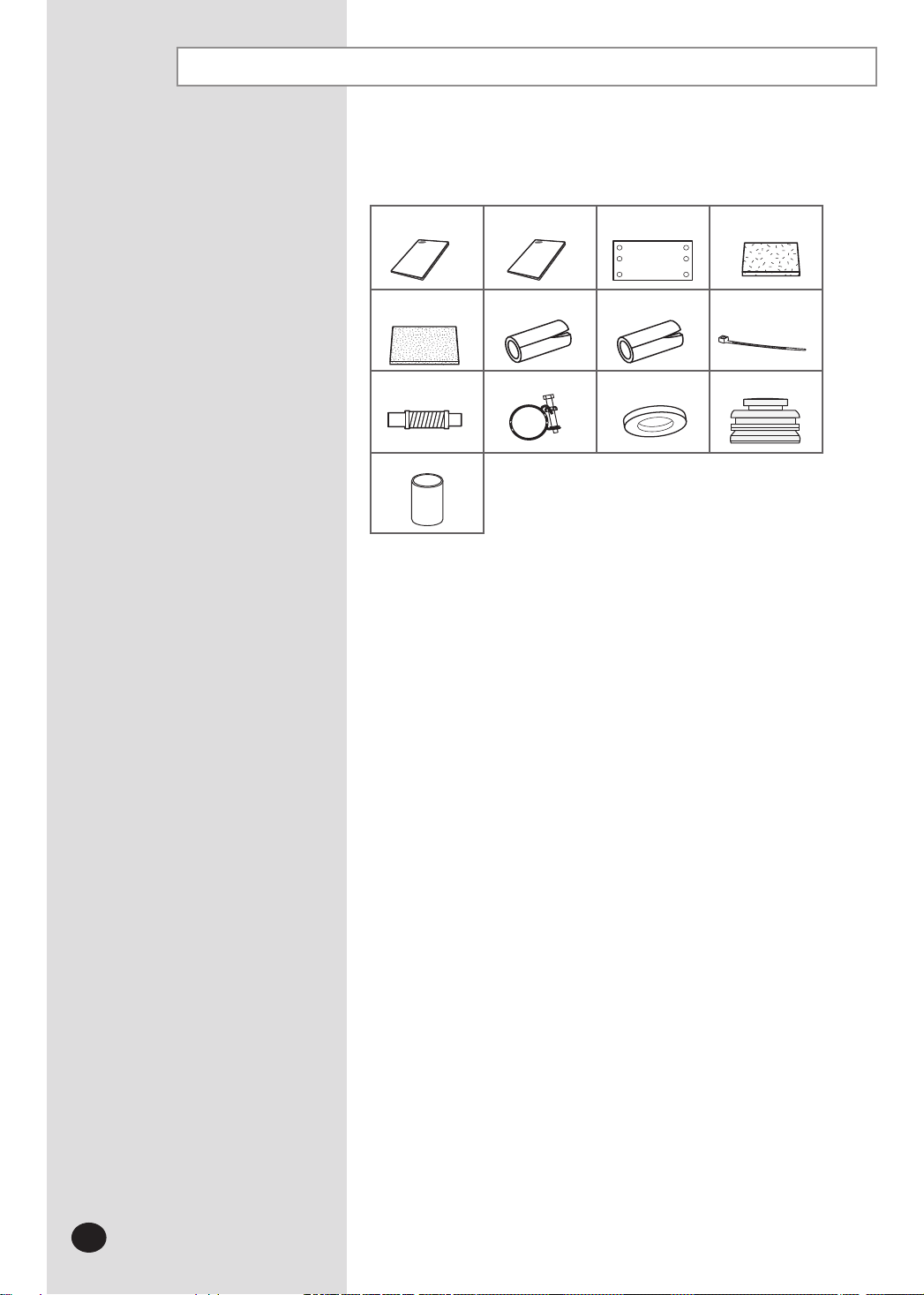
Accessories
The following accessories are supplied with the indoor unit.
The type and quantity may differ depending on the specifications.
User's
manual
Insulation cover
pipe out
Sleeve
Installation
manual
Insulation pipe(A) Insulation pipe(B)
Pattern sheet
WasherClamp hoseFlexible hose
Insulation cover
pipe in
Cable tie
Rubber
E-6
Selecting the Installation Location
Indoor Unit
There must be no obstacles near the air inlet and outlet.
Install the indoor unit on a ceiling that can support its weight.
Maintain sufficient clearance around the indoor unit.
Make sure that the water dripping from the drain hose runs away correctly and safely.
The indoor unit must be installed in this way, that they are out of public access. (Not touchable by the users)
After connecting a chamber, insulate the connection part between the indoor unit and the chamber
with t10 or thicker insulation. Otherwise, there can be air leak or dew from the connection part.
Rigid wall without vibration.
Where it is not exposed to direct sunshine.
Where the air filter can be removed and cleaned easily.
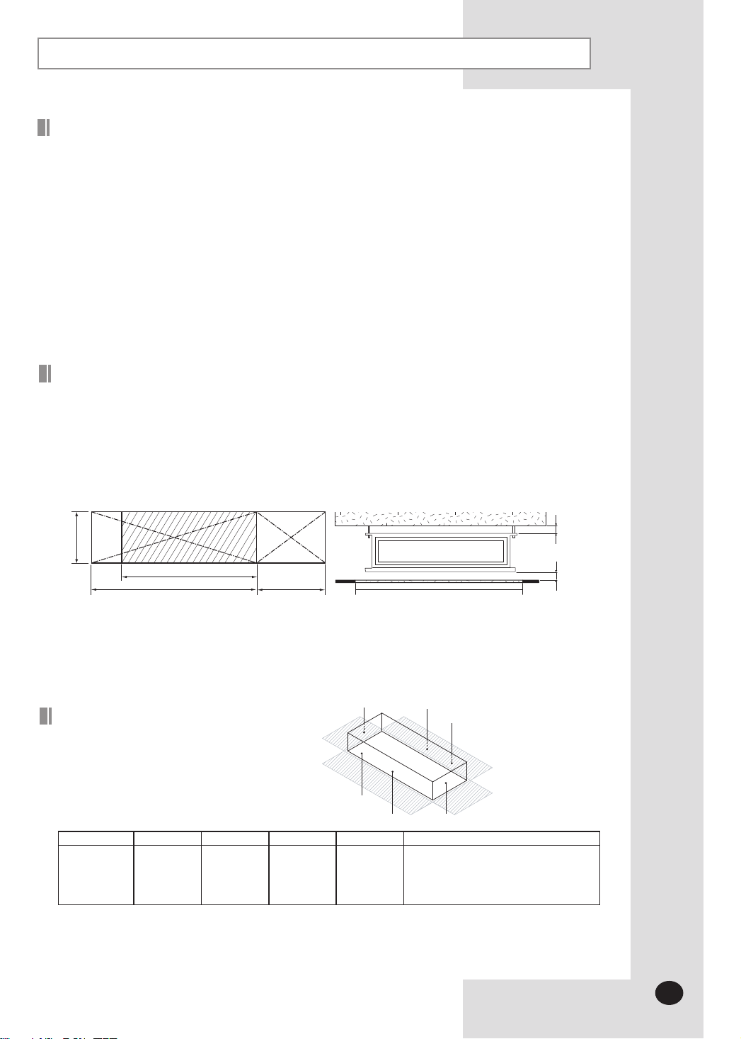
Space requirements for installation & service
Construction Standard for Inspection Hole.
1) In case, the ceiling is textile, Inspection hole dose not need.
2) In case, the ceiling is plaster board, Inspection hole depends on Inside height of the ceiling.
a. Height is more than 1m : Only “B” [Inspection for PBA] is applied.
b. Height is less than 1m : Both “A” & ”B” are applied.
c. “A” & ”B” are inspection holes.
Unit Depth(D)+50mm
You must have 20mm or more space between the ceiling and the bottom of indoor unit. Otherwise, the noise from the vibration of
indoor unit may bother the user. When the ceiling is under construction, the hole for check-up must be made to take service, clean
and repair the unit.
It is possible to install the unit at an height of between 2.2~2.5m from the ground, if the unit has a duct with a well defined lenght
(300mm or more), to avoid fan motor blower contact.
Insulation Guide
Thickness: more than 10mm
Indoor unit A B C D Front/Back
20.0~28.0kW
(1240x470x1040)
Unit Width(W)
“A”=W+100mm “B”=500mm
D
Front
1240x1040 1240x1040 470x1040 470x1040
B
Back
A
C
Insulate the front and back side
in proper size at the same time
when insulating the suction duct
and discharge duct.
I nsulate the end of the pipe and some curved area by using separate insulator.
I nsulate the discharge and suction part at the same time when you insulate connection duct.
20mm or more
20mm or more
E-7
Selecting the Installation Location (Continued)
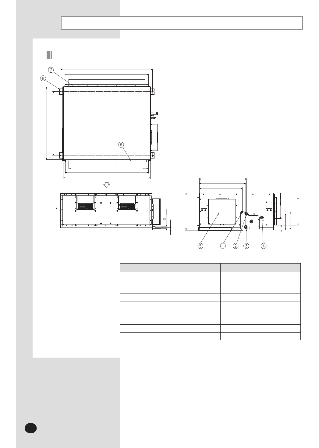
Drawing of the indoor unit
1040
914 Suspension position
1306 Suspension position
1188 Air inlet duct flange
140X8=1120
140X8=1120
1188 Air outlet duct flange
1240
Unit : mm
34
660
647
598
22
93
470
35
OD 32
Discharge side Suction side
385
100X2=200
209
236
29
E-8
No. Name Description
①
②
③
④
Drain pipe connection (Option drain pump)
⑤
Power supply/Communication connection
⑥
⑦
⑧
Liquid pipe connection
Gas pipe connection
Drain pipe connection
Air discharge grille flange
Air suction flange
Hook
ø9.52 (3/8”)
ND200/220
:
ø19.05(3/4”)
ND280 : ø22.22(7/8”)
VP25 (OD ø32, ID ø25)
VP25 (OD ø32, ID ø25)
3/8”
or M10
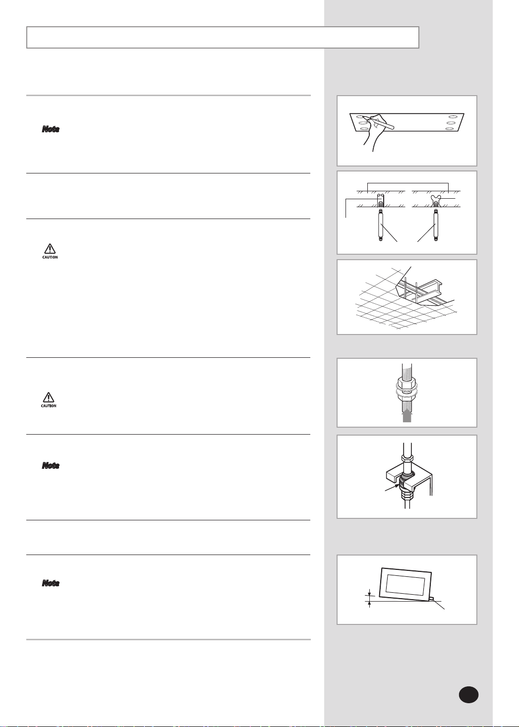
Indoor Unit Installation
It is recommended to install theY-joint before installing the indoor unit.
Place the pattern sheet on the ceiling at the spot where you want to install the
1
indoor unit.
Note
Since the diagram is made of paper, it may shrink or stretch slightly
due to temperature or humidity. For this reason, before drilling the
holes maintain the correct dimensions between the markings.
Insert bolt anchors, use existing ceiling supports or construct a suitable support
2
as shown in figure.
Install the suspension bolts depending on the ceiling type.
3
Ensure that the ceiling is strong enough to support
the weight of the indoor unit.
Before hanging the unit, test the strength of each
attached suspension bolt.
If the length of suspension bolt is more than 1.5m,
it is required to prevent vibration.
If this is not possible, create an opening on the false
ceiling in order to be able to use it to perform the required
operations on the indoor unit.
Screw eight nuts to the suspension bolts making space for hanging the
4
indoor unit.
You must install the suspension bolts more than four when
installing the indoor unit.
Hang the indoor unit to the suspension bolts between two nuts.
5
Note
Piping must be laid and connected inside the ceiling when
suspending the unit. If the ceiling is already constructed, lay the
piping into position for connection to the unit before
placing the unit inside the ceiling.
Hole in anchor
Hole in plug
Suspension bolt(
Rubber
Concrete
3/8”
or M10)
Ceiling support
Insert
Screw the nuts to suspend the unit.
6
Adjust level of the unit by using measurement plate for all 4 sides.
7
Note
For proper drainage of condensate, give a 1° slant to the left or
right side of the unit which will be connected with the drain hose,
as shown in the figure. Make a tilt when you wish to install the
drain pump, too.
1°
Drain hose port
E-9
 Loading...