

Samsung MySono 201 Service manual

Mysono 201 Contents
1. What is Mysono201?
CONTENTS
A TABLE OF CONTENTS
Section 1. Basic Information
2. Mysono201 Configuration
2.1 Main body
2.2 Monitor
2.3 Probe
2.4 Accessory
2.5 peripheral unit (Option)
3. Safety precautions
3.1 Safety standard
3.2 Electrical safety
3.2.1 Protection of equipment
3.2.2 Battery safety
3.2.3 Symbol
3.3 Physical safety
3.4 Maintenance and cleaning
3.4.1 Probe
3.4.1.1 Cleaning
3.4.1.2 Disinfection and Sterilization
3.4.2 Biopsy guide adapter and Needle guide
3.4.2.1 Stainless biopsy guide cleaning
3.4.2.2 Stainless biopsy guide steriliz ation
3.4.2.3 Plastic biopsy guide cleaning
3.4.2.4 Plastic biopsy guide sterilization
3.4.3 The surface of equipment
3.4.1 Cleaning
3.4.2 Sterilization
4. Mysono201 installation
4.1 Probe setting and removing
4.2 Battery setting and removing
4.3 Battery charging and discharging
4.4 System power ON / OFF
4.5 Using AC adapter
5. Mysono201 Function
Mysono201 Precautions Check List
Service Manual Published by Customer Service Department

Mysono 201 Contents
A TABLE OF CONTENTS
Section 2. Description of System
1.System Block Diagram
2. Front End Board (F/E)
2.1General Description
2.2 Block Diagram
2.3 Signal Definition
2.3.1 CPLD Signal Definition
2.3.2 Connector signals between DSC and FE
2.3.3 Connector signals between Power and FE
2.3.4 Connector signals between FE Adapter and FE
2.3.5 Connector signals between FE Adapter and SPC(System Probe Connector)
2.3.6 Connector signals between SPC(System Probe Connector) and Probe
2.4 Scanline Definition
2.4.1 Normal Mode
2.4.2 Synthetic Mode
2.5 Pulser vs Elements
2.6 Specific Description
2.6.1 TGC Amp
2.6.2 Reordering
2.6.3 LPF
2.6.4 Beamfoming IC MCB014A
2.7 PCB Board Lay Out
2.7.1 F/E Top Side
2.7.2 F/E Bottom Side
2.8 Timing Chart
2.8.1 Normal TX Focusing
2.8.2 Synthetic TX Focusing
2.8.3 Control Timing
2.9 Wave Form
3.DSC Board
3.1. Description Overall
3.2. Block Diagram
3.3 Signal Definition
3.4 Specification explain
3.4.1 B/W Data Receiving & FM storing Part
3.4.1.1 Mid Processor (MGA015)3.4 Specification explain
Service Manual Published by Customer Service Department

Mysono 201 Contents
A TABLE OF CONTENTS
Section 2. Description of System
3.4.1.2 Pattern generator
3.4.1.3 Before FM controller (MGA001)
3.4.1.4 FM controller (MGA001)
3.4.2 Frame Memory & Cine Memory Flash Memory Part
3.4.2.1 Frame Memory (VRAM)
3.4.2.2 Cine Memory (DRAM)
3.4.2.3 Flash Memory
3.4.2.4 Memory Path by mode
3.4.2.5 Scanline Masking Window
3.4.3 CRD, Graybar, Overlay Post Memory Part
3.4.3.1 CRD
3.4.3.2 Graybar
3.4.3.3 Overlay
3.4.3.4 Overlay Control Scheme
3.4.3.5 Post Memory
3.4.4 Non interlace Output Display Path part
3.4.4.1 Function
3.4.4.2 VGA
3.4.4.3 VHS
3.4.4.3.1 74ACT715 control
3.4.4.4 Non Interlaced B/W (NI B/W)
3.4.5 Interlace TSC/PAL Display Part
3.4.5.1 Frame Grabber CPLD & Memory
3.5 PCB Board Lay Out
3.5.1 DSC Top Side
3.5.2 DSC Bottom Side
3.6 Timing Chart
3.6.1 CRD Timing Chart
3.7 Wave Form
4. Power B/D
4.1 Specification
4.2 Block Diagram
4.3 Specification explain
5.Probe
5.1.General Description
Service Manual Published by Customer Service Department

Mysono 201 Contents
A TABLE OF CONTENTS
Section 2. Description of System
5.2. Specification explain
5.3 Probe Connector Pin Define
5.4 Signal Definition
5.5 Probe ID
5.6 PCB Lay Out
5.6.1 PB Main Top Side
5.6.2 PB_ODD Top/Bottom Size
5.6.3 PB_EVEN Top/Bottom Size
6.ASIC Data Sheet
6.1 MAGA0010A Manual (draft): Frame Memory Controller
6.1.1 Description
6.1.1 Description
6.1.3 PIN Diagram
6.2 MAGA003A Manual (draft): Clocks Generators
6.2.1 Description
6.2.2 Main Features
6.2.3 Block Diagram
6.2.4 Pin Diagram
6.3 MAGA005 Manual
6.3.1 Description
6.3.2 Block Diagram
6.3.3 Pin Diagram
6.4 MCB014 Manual
6.4.1 Main Features
6.4.2 Block Diagram
6.4.3 Pin Diagram
6.5 MGA015A Manual
6.5.1 Main Features
6.5.2 Block Diagram
6.5.3 I/O Signal Overview
6.5.4 PIN Diagram
7. I/O Map
Service Manual Published by Customer Service Department

Mysono 201 Contents
.
A TABLE OF CONTENTS
Section 3. Sub Apparatus
1.LCD
1.1 General Description
1.1.1General Display Characteristics
1.2 Maximum Ratings
1.3 Electrical Specifications
1.4 Optical Specifications
1.5 Interface Connections
1.6 Power Sequence
1.7 Mechanical Characteristics
1.8 International Standards ( TBD )
1.8.1. Safety
1.8.2. EMC
1.9 Handling Precautions
1.9.1.Mounting Precaution
1.9.2. Operation Precaution
1.9.3 Electrostatic Discharge Control
1.9.4 Precaution For Strong Light Exposure
1.9.5 S torage
1.9.6 Handling precautions For Protection Film
1.9.7 Safety
A 1 Brightness
A 2 Response Time
A 3 Viewing angle
2. Adapter
2.1 Spec. and Range of application
2.2 Block Diagram
2.3 Schematic Diagram
Section 4. Trouble Shooting
1. Trouble shooting
1.1 System Booting Diagnosis
1.2 Image1 Diagnosis
1.3 Battery Diagnosis
1.4 Etcetera Diagnosis
2. Debug Mode
2.1 Debug Menu
Service Manual Published by Customer Service Department

Mysono 201 Contents
A TABLE OF CONTENTS
Section 4. Trouble Shooting
2.2 Image Memory Debugger Menu
2.3 Keyboard Menu
2.4 Biopsy Menu
2.5 Monitor Menu
2.6 8085 I /O Debugger Menu
Section 5. Replacement Procedures
1.Spare Parts Assembling Diagram
1.1 TFT LCD Monitor Replacement Method
1.2 KEY Matrix PCB Replacement Method
1.3 Trackball Replacement Method
1.4 Each PCB Board Replacement
1.4.1 DSC Board Replacement Method
1.4.2 Front End Board Replacement Method
1.4.3 Power Board Replacement Method
2.Parts List
2.1 Cover Body Bottom Assy Exp.
2.2 Power Assy Exp.
2.3 AY_FE_Board_Exp.
2.4 Adapter B/D Exp.
2.5 Cover Assy Body Top Mysono Exp
2.6 SPC Board Assy Exp.
Section 6. Additional Information
1.Specification
1.1 Technical Specification
1.2 Safety Standard
1.3 Range of measurement and accuracy
1.3.1 B mode Range and accuracy
1.3.2 M mode Range and Accuracy
2. Mysono 201 Compatibility Matrix
Service Manual Published by Customer Service Department

Mysono 201 Section 1. 1
1. What is Mysono201?
l Mysono201 manufactured by Medison Co.,Ltd is the newest subminiature and portable
ultrasound system with high resolution, deep transmission and variable function for
measurement.
l The several probes such as Curved probe, Linear probe are available for wide usage.
Mysono201 can be used in a variety of applications Abdomen, Obstetrics, Gynecology,
Vascular, Extremity, Pediatric, Cardiac, Urology.
l Mysono201 offers to excellent image quality, several measurement functions such as a
standards distance, area, girth, volume by application for Obstetrics, Cardiac, etc.
Service Manual Published by Customer Service Department
Mysono 201 Section 1-2. System Constitution
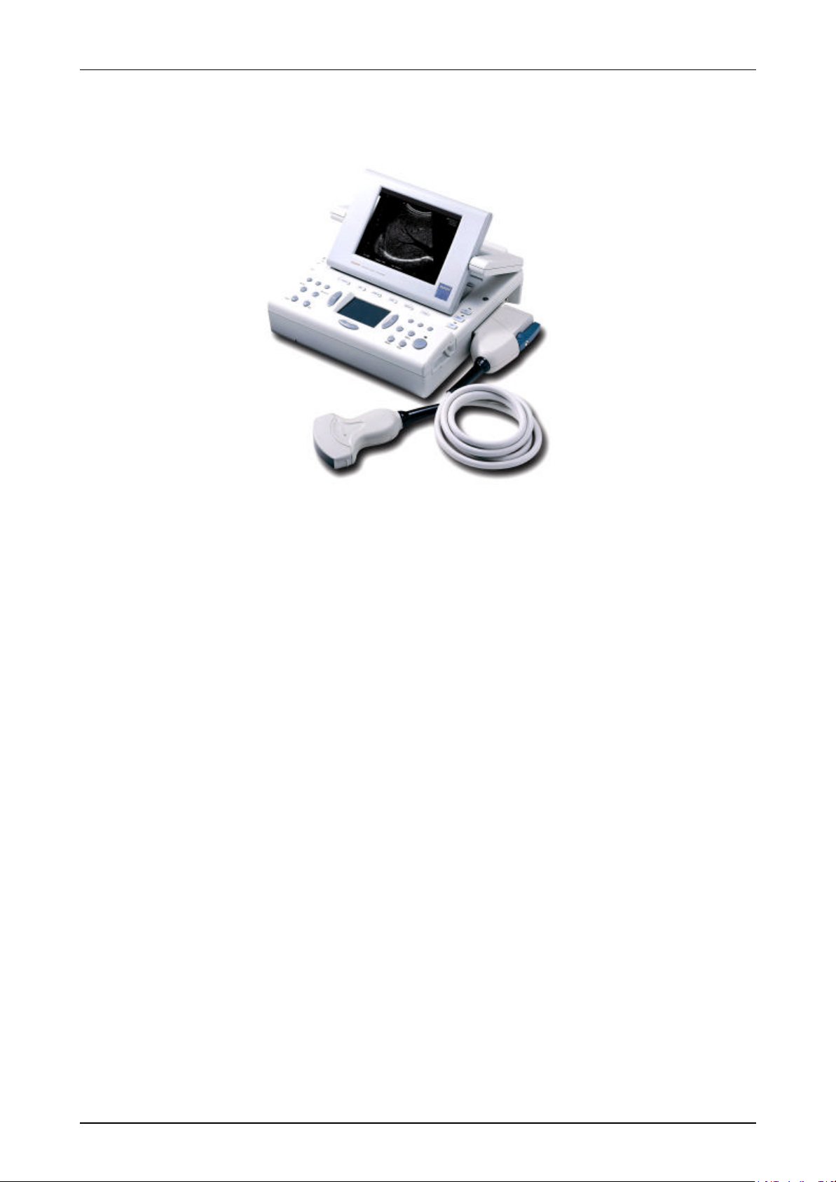
2. System constitution
The system consists of main body, monitor, probe, accessory, etc.
[Figure 1.1 Mysono201]
MEDISON or local distributor will make available on request circuit diagrams, components
part list, descriptions, calibration instructions or other information which assist your
appropriately qualified technical personnel to repair those parts of equipment which are
designed by Medison as repairable
2.1 Main body
The system is classified by inside for making ultrasound image and by outside for connection
to other parts. The housing of system has controllers, probe connector, connector for monitor
or other accessories, handle and power switch.
Service Manual Published by Customer Service Department
Mysono 201 Section 1-2. System Constitution
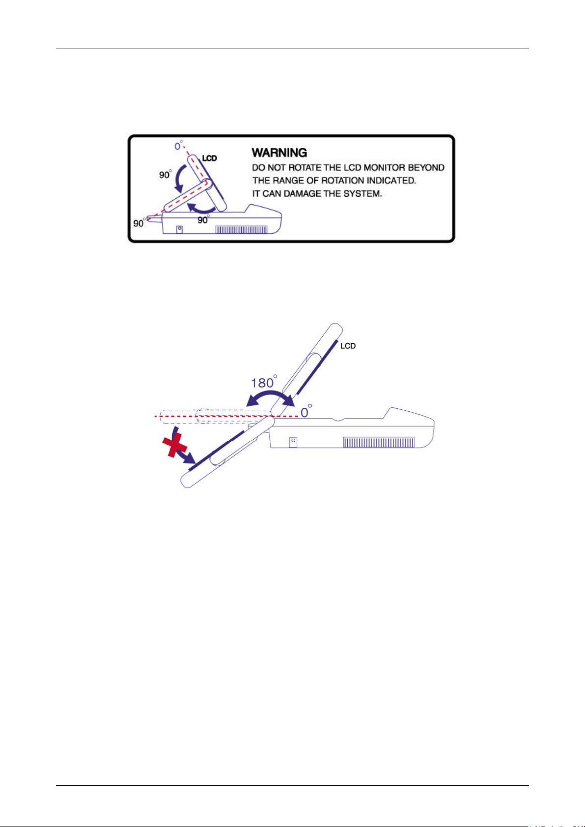
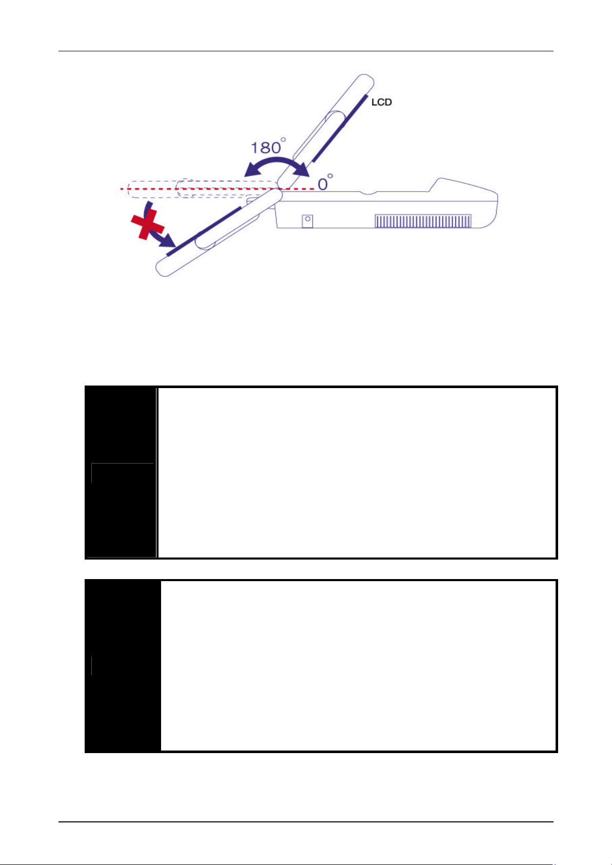
2.2 Monitor
It is TFT LCD Monitor and displays ultrasound image and related information.
It connects to the main body lack of which can control the angle and the height.
[Figure 1.2 LCD Warning]
[Figure 1.3 LCD Warning]
Service Manual Published by Customer Service Department

Mysono 201 Section 1-2. System Constitution
Small parts(Breast / Thyroid / Testicle), Muscular,
Small parts(Breast / Thyroid / Testicle), Muscular,
Small parts(Breast / Thyroid / Testicle), Muscular,
2.3 Probe
Probe generates ultrasound beam and gain the data for display the image.
Probe list and BIOPSY kit available Mysono201 is as follows;
ID Probe Biopsy kit
12 L4-7CD
13 L5-9CD
14 L5-9/60CD
00 C2-5/60BD Reserved Abdomen, Obstetrics, Gynecology, Fetal heart
03 C4-7BD
EC4-
04
Human : Image setting, Safety, EMC, AP&I, QA – Total 6 Probe Release.
9/13CD
Vaginal
BPL-50/65
BPL-75
BPL-50/65
BPC-50 Abdomen, Obstetrics, Gynecology, Fetal heart,
BPC-65-E/C Obstetrics, Gynecology, Urology
Application
Mysono201(Human)
Skeletal, pediatric, Peripheral-vascular
Skeletal, pediatric, Peripheral-vascular
Skeletal l, pediatric, Peripheral-vascular
Pediatric
2.4 Parts
There are supplied with main body.
① Coupling gel
② Power code
③ Power adapter
④ Battery (Option)
⑤ RCA Jack
⑥ Video output cable
⑦ Portable Case
⑧ Operation manual (User guide)
⑨ Smart media (Option) – available hereafter
2.5 Accessories (Option)
It is the optional accessories to connect to the main system. Please refer to supplement OB of
user guide.
① B/W Printer
② VCR
③ Non-Interlaced B / W Monitor
④ VGA Monitor
⑤ VHS Monitor
⑥ HMD
Service Manual Published by Customer Service Department

Mysono 201 Section 1-3. Safety Precaution
3. Safety Precautions
[Notes to users]
Thank you for purchasing the Mysono201 Ultrasound system.
To ensure safe operation and long terms performance stability, it is essential that you fully
understand the functions, operating and maintenance instructions by reading this manual
before operating your equipment. The system must be operated only by, or under supervision
of a qualified person.
“Warning” is used to indicate the presence of a hazard that can cause severe personal injury,
death, or substantial property damage if the warning is ignored.
“Caution” is used to indicate the presence of a hazard that will or can cause minor personal
injury or property damage if the warnings ignored.
“Note” is used to notify the user of installation, operation, or maintenance information that is
important but not hazard related. Hazard warnings should never be included under the Note
signal word.
3.1 Safety Precautions
l Classification:
- Class I equipment with Type BF applied parts
- Ordinary Equipment
- Non-AP/APG
l Electromechanical safety standards met:
_ CSA C22.2 No.601.1, Canadian Standards Association, Medical Electrical Equipment
- EN60601-1, Second Edition, including Amendments 1 and 2, European Norm, Medical
Electrical
l Equipment
- EN60601-1-2, First Edition, European Norm, Collateral Standard, Electromagnetic
Compatibility
- IEC61157: 1992, International Electro technical Commission, Requirements for the
declaration of the acoustic output of medical diagnostic ultrasonic equipment
- UL 2601-1, Underwriters Laboratories, Medical Electrical Equipment
Service Manual Published by Customer Service Department

Mysono 201 Section 1-3. Safety Precaution
e. If any repairing or exchanging
If it has any crack
ital
interface of which achieved IEC certificate. (I.e. IEC60950/EN60950 for the
peripheral device of input or output port meet standard
patient at the same
It is for preventing to leakage current caused by over the maximum
Even though the system passed the test of EMI/EMC standard, it could be
down the image quality or could damage the system under using magnetic
omagnetic waves is near of the system or not such as Mobile phone,
Pager, Radio, TV or Microwave machine. Please move them far from the
s in dry condition such like under using
occurred by a user or a patient can affect to the system
, please be well aware as
3.2 Electrical Safety Precaution
It is classified Class I equipment with Type BF applied parts
To ensure user safety, check the following.
Never open the system safety cover.;
There is a dangerous voltage in system insid
of parts is desired, ask to the authorized dealer for the service.
Do not place the system near of flammable gas or anesthesia gas. It has a
danger of explosion.
Before using the system, check the housing and the cables.
on the housing or wear away on cable, stop to use.
Whenever cleaning the system, take off the power code and the battery to
avoid the danger of an electric shock.
WARNING
To avoid the danger of an electric shock, use the standard device for dig
data processing device, IEC60601-1/EN60601-1 for medical device.)
For the more, all parts of system meet standard requirement of IEC60601-11/ EN60601-1-1.
Check whether the
requirement of IEC60601-1-1/EN60601-1-1 when add it.
Do not connect to the system signal in/outlet and the
time.
permissible range.
filed.
If you have a poor image or image problem, check whether the source of
electr
system or move the system from affected zone of electromagnetic waves.
CAUTION
Service Manual Published by Customer Service Department
Electrostatic discharge (ESD) is a shock occurred by Static electricity and a
phenomenon in nature. ESD occur
heater or air conditioner.
The static electricity
or the probe sometimes. To prevent this problem
follow.
: - Spray the prevent of static electricity spray to carpet or Linoleum
- Use met for protection of static electricity
- Connect a ground between the system and table or bad for patient
Mysono 201 Section 1-3. Safety Precaution
In case that tie too much or twist the probe connected with patient, system
3.2.1 System care
Check the following.
could be wrong work.
Wrong cleaning or sterilization of the parts connected with patient is
dangerous.
Refer to “3.4 Maintenance & Cleaning” in this manual.
Do not soak the cable in liquid. It cannot prevent flood.
Do not use strong solvents such as thinner or benzene, or abrasive
cleansers.
CAUTION
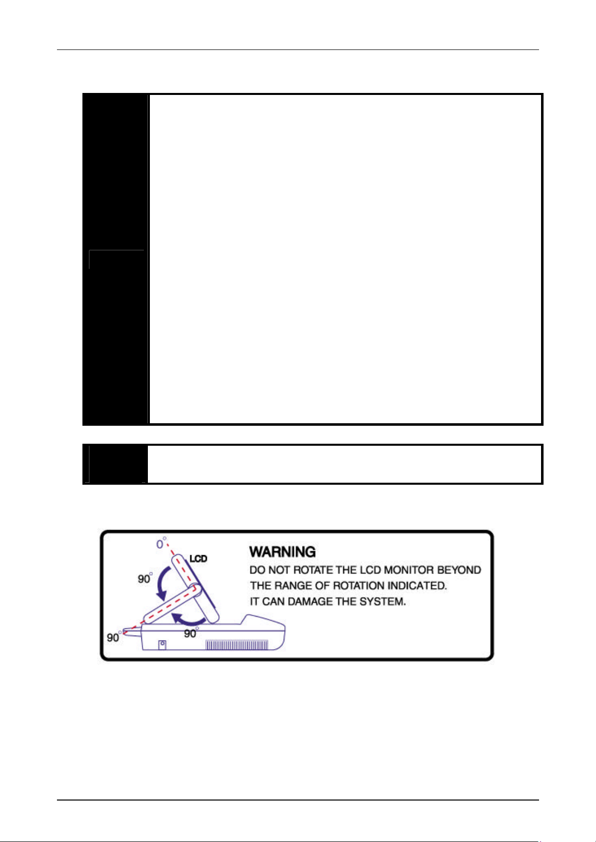
WARNING The turning radius is limited to suitable use. If it is over the limitation, that
Since these will damage the cabinet.
In general, only treat with waterproof on the ultrasound lens part (Safety
grade: IPX7). Do not soak the probe in liquid except the special case with
cleaning guide.
Do not turn the system off under store the image. That will damage the
memory inside.
Turn the system off when remove the probe form the system or connect it
to the system.
Do not keep the system over one hour with close LCD monitor under the
system is working. That will damage the keyboard.
will damage LCD monitor.
[Safety Figure1. Warning for LCD angle]
Service Manual Published by Customer Service Department
Mysono 201 Section 1-3. Safety Precaution
If smell or burn under using battery, discontinue use of system prompt,
System working condition and a number of charge/discharge times of
[Safety Figure2. Warning for LCD angle]
3.2.2 Battery
Keep in mind the warning and caution to prevent explosion, heat or smoke generation in
battery.,
Do not disassemble or modify the battery.
Keep the circumstance temperature condition when using the battery.
- Charge: 0O ~ 45 O C
- Discharge: -10O ~ 60 O C
Do not short between terminals of battery.
WARNING
CAUTION
Do not use the battery under the circumstance like as fire, moisture.
Do not charge the battery where is near of fire or heater.
Keep out of the sun when keep the battery.
Keep out the sharp material to face with battery and do not deliver the
shock directly to it.
Take away the battery from the system when do not use it for a long time.
Do not use the battery except supplied by Medison
Do not use a battery except made by Medison.
Do not charge a battery with non- allowed method.
(Don’t use other charge method)
Keep a battery from moisture.
remove a battery.
Keep the battery under the circumstance temperature -20O ~ 50 O C.
battery affect to time of charge/discharge.
Medison guaranty the battery during 6 month (battery capacit y 50%).
Service Manual Published by Customer Service Department
Mysono 201 Section 1-3. Safety Precaution
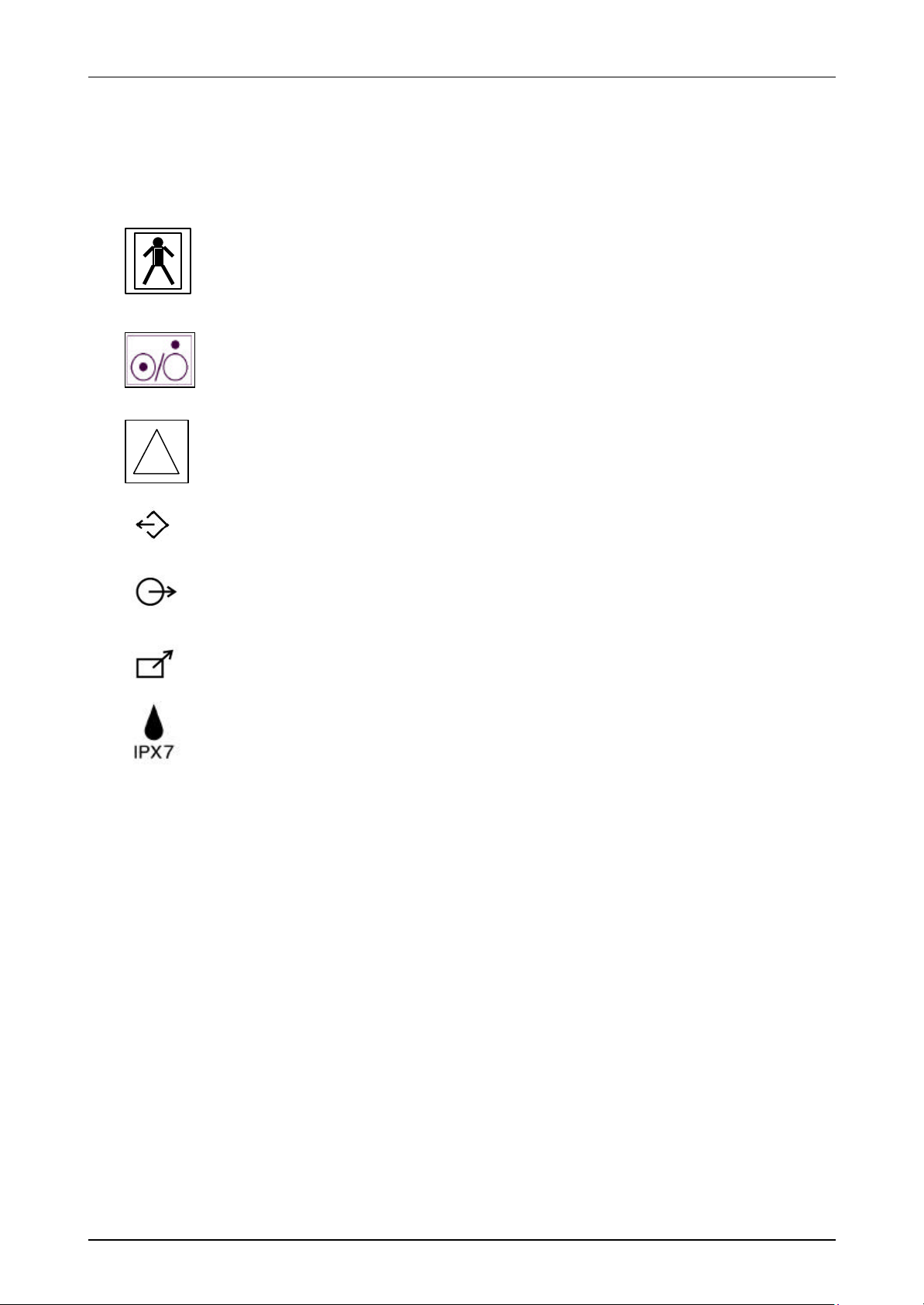
3.2.3 Safety Symbols
The international Electrotechnic Commission (IEC) has established a set of symbols for
medical electronic equipment that classify a connection or warm of any potential hazards. The
classifications and symbols are shown below.
Isolated patient connection (IEC 601-1-Type BF)
!
Power Switch represent ON and OFF, respectively.
This symbol identifies a safety note. Ensure you understand the function of
this control before using it. Control function is described in the appreciate
operation manual.
Output port or Parallel port of VGA
Output port of VHS
Non-interlaced B/W Printer port
Printer remote output port
Humidity protect
Service Manual Published by Customer Service Department

Mysono 201 Section 1-3. Safety Precaution
immediately, and contact to Service center or its authorized dealer for
3.3 Physical Safety Precaution
If you have experienced any trouble with the equipment, switch it off
assistance.
Do not use the system under working wrong or trouble.
Non-continuous scanning is caused by hardware problem. It must be
WARNING
ALARA TRAINING PROGRAM
Ultrasound is considered safe at low clinical levels. At high levels and longer exposures,
however, its safety is not completely understood. For this reason, always exercise caution when
exposing patients to ultrasound. Always use the lowest transmit power levels.
And minimize time of exposure. Under the principles of ALARA, energy delivered should be “as
low as reasonable achievable ” to perform your study.
repaired.
The using of Ultrasound always needs a careful attention.
Under the principles of ALARA, energy delivered should be “as low as
reasonably achievable ” to perform study.
Read the explanation about biopsy before using it. Refer to user
explanation parts of probe an appendix.
Certify biopsy Needle before using it. Do not use curved needle.
The following is a public statement by the one of United Stated Ultrasound Association, AIUM,
on the safety of ultrasound diagnosis.
Ultrasound has been in use since the 1950’s. AIUM declares the clinical safety of ultrasound
scanning and acknowledges its effectiveness as the type medical equipment and its possible
use for diagnosis of pregnant women.
There has been no case which shows cause of any physical damage to either patient or user
during properly performed diagnosis with an ultrasound scanner. Although it might be possible
that unknown effects of ultrasound may come to light in the future, so far the benefits far
outweigh any unproved danger. Theoretically, there are two possible ways that ultrasound
could have negative affect on the human body.
One is the heat generated by ultrasound as it passes through the human body. Doppler
produces the most heat, and it followed by color and B-mode imaging. However, even in the
case of Do ppler the amount of heat is so minor that there is no equipment that can measure it.
The other one is the possible formation of a cavity by the ultrasound. However, there has been
no clear evidence that this can actually occur in the human body.
In conclusion, no negative biological effects of ultrasound have been proven thus far.
Service Manual Published by Customer Service Department
Mysono 201 Section 1-3. Safety Precaution
the system, turn off the power and remove
the plug from the power supply. (Remove the battery from the system,
Always use protective eyewear and gloves when cleaning and disinfecting
Probes must be cleaned after each use. Cleaning the probe is an essential
probe that must remain dry higher than the wetted parts until all parts are
3.4 Maintenance and cleaning
Whenever maintain or clean
WARNING
too)
3.4.1 Probe
WARNING
CAUTION
Probe is very important part to judge the image quality. The optimum image can display under
using the correct probe.
3.4.1.1 Cleaning
probes and Biopsy guide adapter.
step prior to effective disinfection or sterilization. Be sure to follow the
manufacturer’s instructions when using disinfectants.
Do not allow sharp objects, such as scalpels or cauterizing knives, to touch
probes or cables.
When handling a probe, do not bump the probe on hard surfaces.
Do not use lacquer thinner ethylene oxide or any other organic solutions,
as these can destroy the membrane of the probe.
Do not use a surgeon’s brush when cleaning probes. The use of even soft
CAUTION
1) Disconnect the probe from the system.
2) Remove any sheaths, biopsy guide adapters, or biopsy needle guides (biopsy guide
adapters are re -usable portion of the biopsy guide and can be sterilized.)
3) Discard sheaths (sheaths are single -use item)
4) Use a soft cloth lightly dampened in a mild soap or compatible cleaning solution to
remove any particulate matter or body fluids that remain on the probe or cable.
5) To remove remaining particulates, rinse with water up to the immersion point.
6) Wipe with a dry cloth; or wipe with a water-dampened cloth to remove soap
residue, and then wipe with a dry cloth.
brushes can damage the probe.
During cleaning, disinfection, and sterilization, orient the parts of the
dry. This will help keep liquid from entering non-liquid-tight areas of the
probe.
Service Manual Published by Customer Service Department
Mysono 201 Section 1-3. Safety Precaution
the solution
expiration date. The level of disinfection required for a device is
the solution strength and duration of contact are appropriate for
s
In neurosurgical application, sterilized probes should be used with a
recommended disinfection solution, incorrect solution
a period longer than
recommended can damage or discolor the probe and will void the
Do not immerse probes longer than one hour, unless they are
id solutions. Using autoclave, gas(EtO),
will damage your probe
3.4.1.2 Sterilization
Apply this sterilization way to EC4-9/13CD probe only.
A 10-6 reduction in pathogens should be reached following the sterilization procedures in this
manual and using the following MEDISON recommended solutions. The following disinfectants
are recommended because of both its biological effectiveness (as qualified through the FDA
510(k) process) and its chemical compatibility with MEDISON ultrasound product materials.
Solution Country Type Active ingredient FDA 510(k)
Cidex USA Liquid Gluteraldehyde K934434
If a pre-mixed solution is used, be sure to observe
dictated by the type of tissue it will contact during use. Ensure that
WARNING
disinfection or sterilization. Be sure to follow the manufacturer’
instructions.
pyrogen-free sheath.
Using a nonstrength, or immersing a probe deeper or for
probe warranty.
CAUTION
sterilizable. Probes may be damaged by longer immersion times.
Sterilize probes using only liqu
or other non-MEDISON-approved methods
and void your warranty.
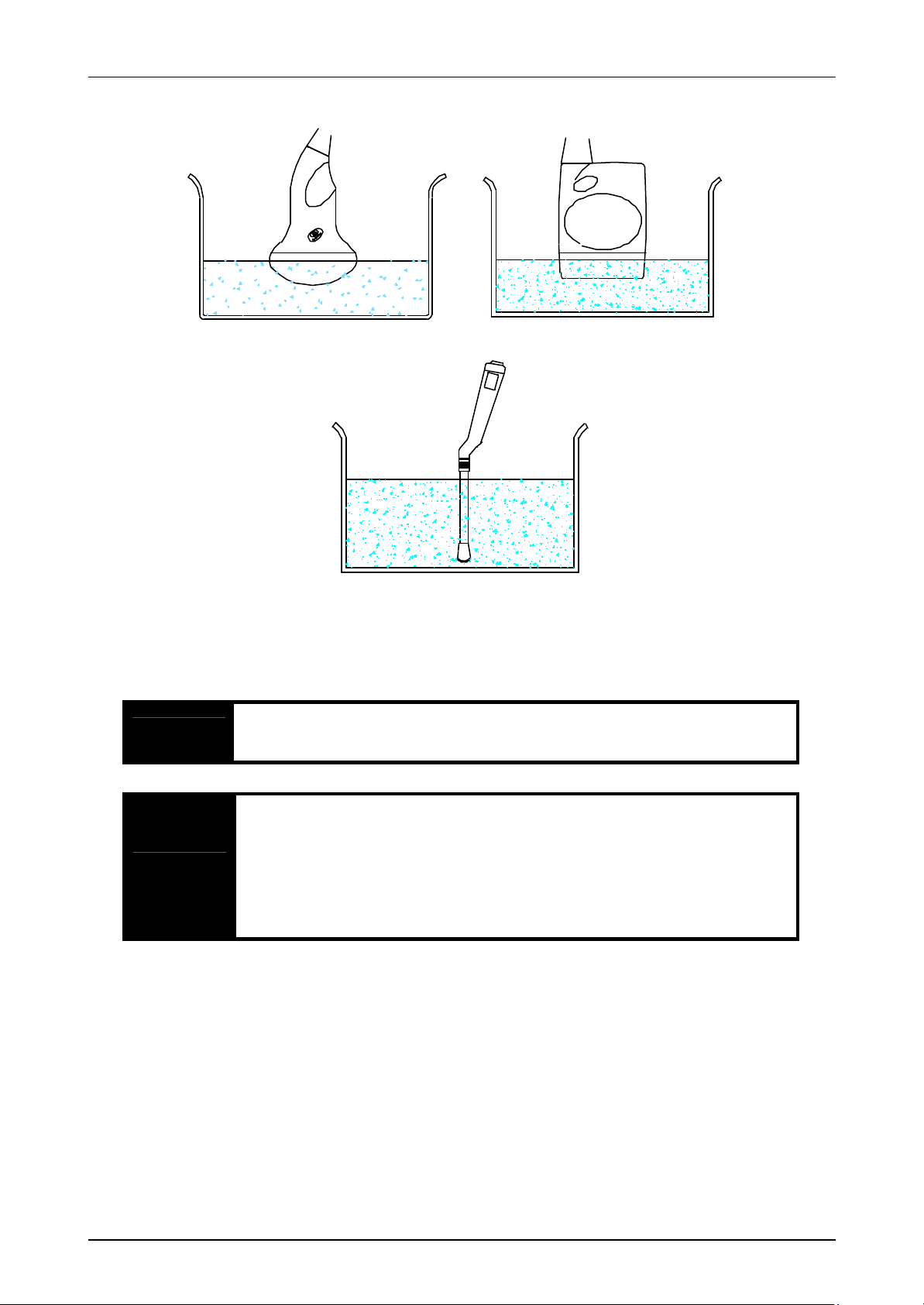
7) Mix the disinfection solution (or sterilization solution, for sterilizable probe)
compatible with your probe according to label instructions for solution strength. A
disinfectant qualified by the FDA 510(k) process is recommended.
8) Immerse the probe into the disinfection solution (or sterilization solution, for
sterilizable probe) as shown in the figures below for your probe.
9) Follow the instructions on the disinfection (or sterilization, for sterilizable probe)
label for the duration of probe immersion. Do not immerse probes longer than one
hour, unless they are sterilizable.
10) Using the instructions on the disinfectant or sterilizatio n label, rinse the probe up to
the point of immersion, and then air dry or towel dry with a clean cloth (or a sterile
cloth, for sterilizable probe).
11) Examine the probe for damage such as cracks, splitting, fluid leaks, or sharp edges
or projections. If damage is evident, discontinue use of the probe and contact your
customer service representative.
Service Manual Published by Customer Service Department
Mysono 201 Section 1-3. Safety Precaution
Gloves and safety mask should be worn during cleaning and sterilizing
user guide published
3.4.2 Biopsy guide adaptor and Needle guide
The reusable external surface of biopsy guide adaptor can sterilize under the condition as
below. It is possible to reduce the pathogens up to 10-6 as following process.
WARNING
CAUTION
3.4.2.1 Cleaning of the stainless biopsy guide
the probe and biopsy guide adapters.
Biopsy guide have to clean after using. It is very important process.
When using the disinfecting solution, follow the
by manufacturer.
Keep out of the sharp things such like a mess for a surgical operation.
Be careful to avoid striking the biopsy guide with hard material.
1) Take off the biopsy guide assembly parts from the probe after using.
2) Disassemble the biopsy guide parts each one.
3) Remove an alien substance still remained on each part using by small brush and water.
4) Rinse it with water to remove again an alien substance.
Service Manual Published by Customer Service Department
Mysono 201 Section 1-3. Safety Precaution
damage by sterilization using autoclave, gas
3.4.2.2 Sterilizing of the stainless biopsy guide
Sterilize it by using an autoclave or Ethylene Oxide.
1) Complete the following process after sterilization.
2) Check the biopsy guide adaptor whether it has a crack, division, or any other damage
on it. If there is some damage, stop to use and contact to Medison service agency or its
authorized local service agency.
3.4.2.3 Cleaning of plastic biopsy guide
Take off the biopsy guide assembly parts from the probe after using.
1) Disassemble the biopsy guide parts each one. The consumable parts cannot sterilize.
2) Remove an alien substance still remained on reusable part using by small brush and
water.
3) Rinse it with water to remove again an alien substance.
3.4.2.4 Sterilizing of plastic biopsy guide
Sterilize only a chemical pasteurization at a low temperature.
CAUTION
4) Sterilize it by using a chemical pasteurization at a low temperature approved by FDA
510(K). Check the time (normal 10 hours) and the temperature of solution.
It is a biologically, chemically suitable disinfecting solution approved by FDA 510(k) in
U.S.A.
Solution Country Type Active ingredient FDA 510(k)
Cidex USA Liquid Gluteraldehyde K934434
Cidex Plus USA Liquid Gluteraldehyde K923744
5) Complete the following process after sterilization.
6) Check the biopsy guide adaptor whether it has a crack, division, or any other damage
It can get the permanent
or radioactivity.
on it . If there is some damage, stop to use and contact to Medison service agency or its
authorized local service agency.
Service Manual Published by Customer Service Department

Mysono 201 Section 1-3. Safety Precaution
Gloves and safety mask should be worn during cleaning and sterilizing
3.4.3 Surface of system
Follow as below..
WARNING
CAUTION Use only the solution recommended by Medison.
3.4.3.1 Cleaning
1) Turn the system off and then remove the plug from the power source.
2) Use a soft cloth lightly moistened with a mild soap or detergent solution to clean the
system surface.
3.4.3.2 Sterilization
3) Use a disinfecting solution with suitable concentration recommended by user guide.
Medison recommend the solution approved by FDA 510(k) in U.S.A.
4) Check the using time and the concentration of the solution as following the caution on
the label.
5) Dry it with a soft sterile cloth.
the surface of system.
Service Manual Published by Customer Service Department

Mysono 201 Section 1-4. Installation
4.Installation of Mysono201
4.1 Connecting and removing the probe
The system has only one probe connector.
l How to connect the probe
1) Connect the probe to the probe connector located at the right side of the system.
2) Turn the locking lever on the probe connector clockwise to fix the probe.
l How to remove the probe
1) Turn the locking lever on the probe connector counter-clockwise to remove the probe.
2) Take off the probe from the system.
4.2 Connecting and removing the battery
It is optional part to supply the battery.
l How to connect the battery
1) Remove the cover of battery connector located at the bottom of system by pushing
forward outside.
2) Insert the battery to the battery connector by matching the bottom of the battery and
the system. After fixing the location of the connector pin between the battery and
system, press it softly until complete the connection.
3) After complete connection, close the cover of battery connector of the system.
l How to remove the battery
1) Turn off the system power.
2) Remove the cover of battery connector located at the bottom of system by pressing
forward outside.
3) Take hold of the battery handle and lift it slightly. Then push it forward outside of the
system.
4) After remove the battery, close the cover of the system battery connector.
4.3 Charge and discharge of the battery
The battery has to charge before using.
l How to charge the battery
1) Insert the battery as how to connect the battery
2) Connect the system and AC adaptor supplied with the system. Refer to [appendix 0b.
connecting the peripheral device] in user manual.
3) The battery is charging during AC adaptor connecting.
It is possible to charge under the state both the system on and off.
Service Manual Published by Customer Service Department

Mysono 201 Section 1-4. Installation
In case of the system on, it takes about 5 hours to charge.
In case of the system off, it takes about 3 hours to charge.
If need a more information of the time for charge or discharge, refer to [Appendix C.
System specification] in the user manual.
Check the battery state by LED color on the system during charging.
- Without Battery: No Color
- Under charging: Orange
- Complete charging: Yellow
- Take off the adaptor: Red
Discharge the battery
When the battery is discharged (the system is working without AC adaptor), the system power
will be compulsorily turned off after a period of time (90 minutes) for safety and efficiency of
battery and user will hear the warning “beep” sound every 10 seconds.
4.4 Power ON / OFF
Hold the pressing the power switch located at the left side of the system for minimum 1sec.
whenever turns on/off the system. It is to prevent the system down and battery discharge.
l How to turn on the system
1) Hold the pressing the power switch for minimum 1sec. with connecting the AC adaptor
or inserting the charged battery.
2) Check the image display on the monitor.
l How to turn off the system
1) Hold the pressing the power switch for minimum 1sec.
2) Check the image disappears on the monitor and switch off.
4.5 Using AC adaptor
It takes about 5 hours to charge completely under connection of AC adaptor to the system.
Refer to [Appendix 0b. connecting the peripheral device] in user manual.
Service Manual Published by Customer Service Department
Mysono 201 Section 1-5. Function
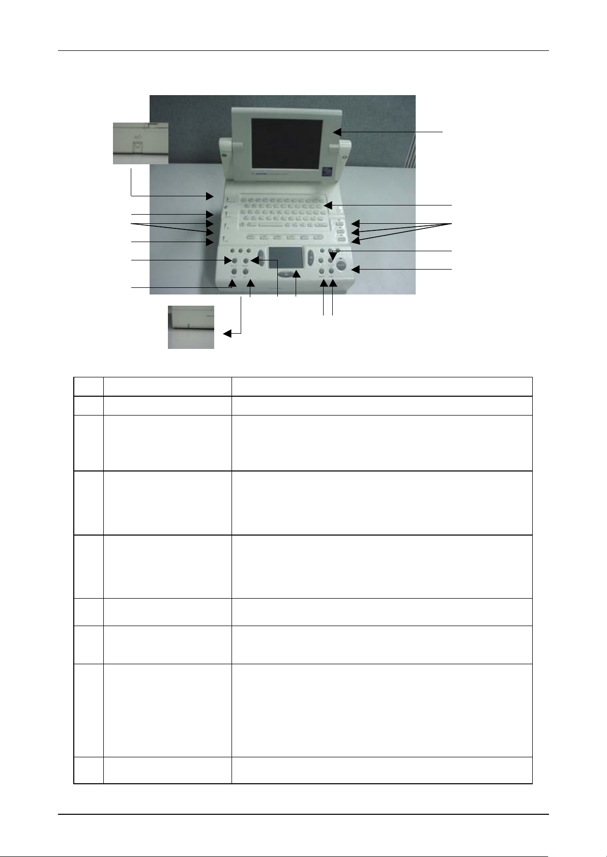
12 3 4 7 5 6 8 9 10 11 12 13 14 15 16 17
5.Mysono201 Function
No.
1 Power switch Turns power on / off à about 1 sec.
2 Brightness
3 Near / Far
4 Gain
5 Set-up Change the mode into set -up
6 Clear
CONTROLS DESCRIPTION
Control the Brightness of LCD monitor.
Turn it to clockwise for brightness
Turn it to counter-clockwise for darkness
Use either Near dial or Far dial
When control the Near gain, use Near dial
When control the Far gain, use Far dial
Control the image gain
Turn it to clockwise for increasing the gain
Turn it to counter-clockwise for decreasing the gain
Delete the value on the image area such as Text, Body
Marker, Indicator, measured value, etc.
Display the status of Battery.
Disconnect the Battery: No Color
7 Battery LED
8 GA Measure GA(Gestational Age)
Service Manual Published by Customer Service Department
Charging the battery: Orange
Full charge: Yellow
Remove the battery adapter: Red

Mysono 201 Section 1-5. Function
And can be back up by using smart media. (This
image saving, printing or measuring
Display 2D image on the left side of the monitor and M
This button works as toggle button between 2D/M and
No.
9 Measure
10 Touch pad Touch pad
11 Depth
12 Printer Print the indicated image.
13 Store
14 Freeze
CONTROLS DESCRIPTION
Mode for measuring of distance, volume, circumference,
etc.
Control the image depth.
Up key for shallow depth of the image
Down key for deep depth of the image
Save the present image on the monitor.
It is possible to check the saved image by using I-View.
function will be added in the future.)
ON/OFF the image scan.
Cine function, the
is available under freeze.
But the image saving is available only 2D mode.
Control knobs to select the image mode
2D/SYN: To 2D mode, press it one time. To Synthetic
mode, press it again under 2D mode.
M: Change 2D/M by pressing this button.
15 2D/SYN, M, DUAL
16 Key board Use it when input the text or set the image.
17 LCD monitor
mode image on the right side of the monitor.
Change only M mode by pressing again this button
under 2D/M mode.
M mode under M mode.
Dual: Change Dual mode.
It works as alteration to left/right of activated Image.
Display most of information for using such like a
ultrasound image, data, user menu, etc.
Service Manual Published by Customer Service Department
Mysono 201 Section 1-5. Function
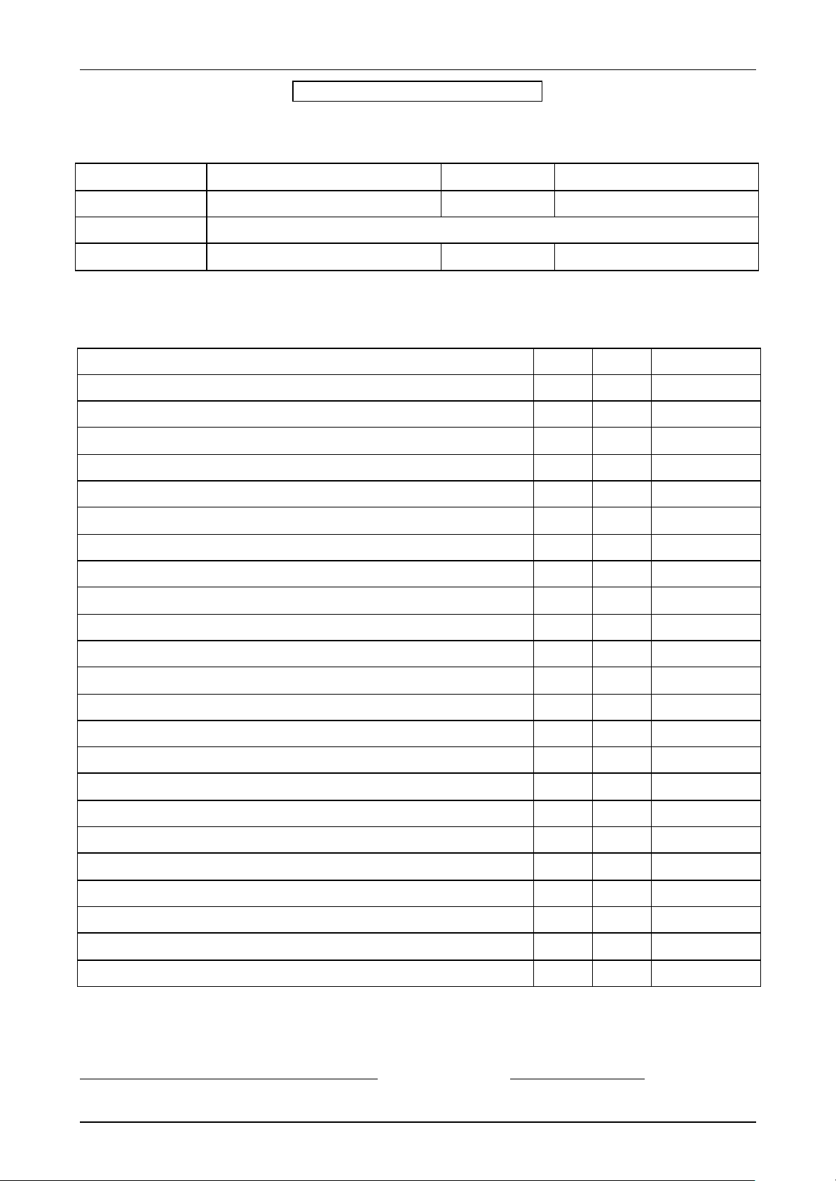
Mysono201 P/M Check List
Date: Distributor :
Hospital System Serial
Customer S/W Version
Address
Tel. no Warranty
Instructions :
This information is for warranty check. Please fill up all items.
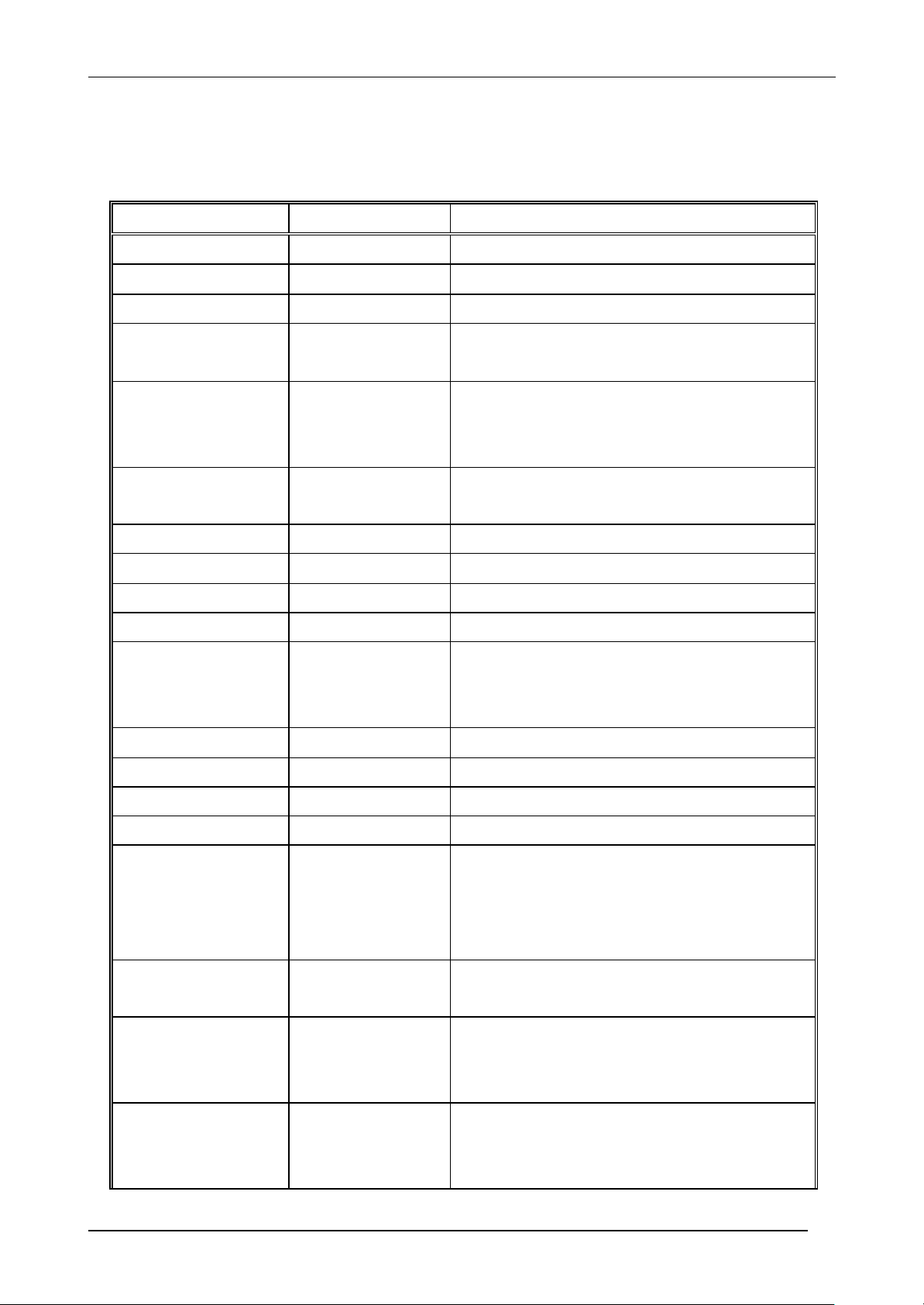
Items Good
Ι . Check the packing items (compare with packing list)
Ι Ι. Condition of system housing
Ι ΙΙ. Probe condition
A. Functional operation & test (system initialization state)
1. System works well when power on.
2. Monitor TEST
3. Key Board TEST
B. Probe test (each probe)
¨ ¨
¨ ¨
¨ ¨
¨ ¨
¨ ¨
¨ ¨
Bad Remarks
1. Check the probe shape
2. Knife TEST
C. Operational Mode Tests
1. 2D Mode/SYN
DUAL Mode
M Mode
2. Measurement TEST
D . Electrical Test & Calibration
1. Power Supply
2. System Calibration
3. Power Cord/Plug and 110/220 switch
E. Mechanical operation
1. Circuit boards, plugs, jacks, and connectors seated
3. Seating & connection of cables & cords to peripherals
F. Echo printer, External monitor, Multi-form camera, VCR
When you finish filling all up, please send this sheet to Medison by fax or air mail.
¨ ¨
¨ ¨
¨ ¨
¨ ¨
¨ ¨
¨ ¨
¨ ¨
¨ ¨
¨ ¨
¨ ¨
¨ ¨
¨ ¨
Confirmation Signature
Service agency: Customer signature
Service Manual Published by Customer Service Department
Mysono201 Section 2-1. System Block Diagram.
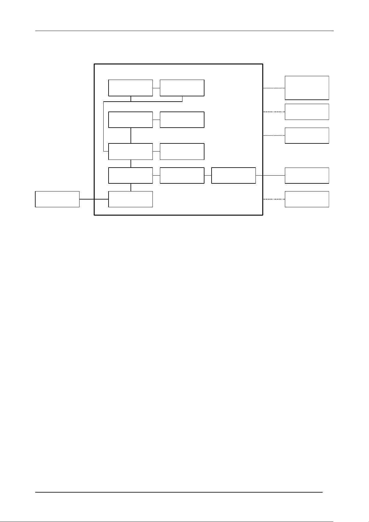
1. System Block Diagram
B/W Printer
LCD Monitor
Key Board
Inverter
Touch Pad
or VCR
or HMD
VGA Monitor
Non-Interlaced B/W
Monitor
Power Adaptor
Digital Scan Converter
(DSC)
Front End
(FE)
Power
System Bolck Diagram
DSC Video Jack
(VJ)
FE Adaptor
System Probe Connector
(SPC)
Probe
Smart Media
Service Manual Published by Customer Service Department

Mysono201 Section 2-2. Front End Board (F/E)
2. Front -End Board (F/E)
2.1 General Description
F/E board receives the echo signal of ultrasound and the signal clamps the high voltage to +/-
0.6 V by Limiter then pass through TGC Amp. And then it reordering and its signal path is
reduced in half by OP Amp Adder that add the Symmetrical signal per scanline.
Then, to reduce the Aliasing, pass through the Low pass Filter and travels it to Beamforming IC
after converting it to A/D. Beamforming IC control the signals of 8 channel by Rx focusing, and
forward them to Mid Processor IC MGA015A on DSC.
Its main components are ;
- MOSFET Driver EL7222 x 16 ea
- PMOS TP2520 x 16 ea
- NMOS TN2524 x 16 ea
- Dual TGC Amp AD604 x 8 ea
- Cross Point Switch (16 x 8) MT8816 x 1 ea
- OP Amp AD812 x 8 ea
- Beamforming IC MCB014A x 2 ea
- XC95144 for Control x 1 ea
2.2 Block Diagram
=
GND
U8 EXT_A[0-20]
BFIC U8
=
U8 EXT_B[0-20]
U7 EXT_A[0-20]
A/D 7
A/D 6
A/D 5
A/D 4
LPF 0~7
Adder
0 ~7
AD812 8 EA
Reordering
16x8 MUX
MT8816 1 EA
TGC AMP
0 ~15
AD604 8 EA
Limiter
0 ~15
Probe
Connector
Pulser
0 ~15
A/D 3
BFIC U7
Clock : 25.2MHz
BF_OUT
U7 EXT_B[0-20]
1
A/D 2
A/D 1
A/D 0
Service Manual Published by Customer Service Department
Mysono201 Section 2-2. Front End Board (F/E)
2.3 Signal Definition
2.3.1 CPLD Signal Definition
Name I/O Description
ADDR[0-5] Input HOST Address
/RPT Input Rate Pulse Train
/P_O_RESET Input Power On Reset by RC Time Constant
DATA[0-7] Input/Output HOST Data
DATA[0-15] for MCB014A(BFIC)
/PRB_INS Input Low : Probe Inserted
High : Probe Not Inserted
If Probe is inserted, then /PRB_INS=Low
FREEZE Input Freeze
If scanning is stopped, then FREEZE=high
/CPU_RD Input HOST I/O Read
MASTER_CK Input 25.2 MHz Clock (50.4MHz/2)
/CPU_WR Input HOST I/O Write
/ETRG Input Exciting Trigger
PRB_ID[0-4] Input Probe Identity Number
PROBE_ID[3] : default Low
PRB_ID[3] is not used.
TDI Input CPLD download T DI
TMS Input CPLD download TMS
TCK Input CPLD download TCK
TDO Output CPLD download TDO
HV_ON Output High : High Voltage On
Low : High Voltage Off
High Voltage On when probe connect to the
system
/AD_EN Output A/D Converter Enable
Default Low
INIT_MODE[2] Output BFIC Initial Mode
Real Mode : High
Download Mode : Low
/TX_MASK Output Tx Fire Disable
Display Low under Probe Disconnection or
Freeze mode
Service Manual Published by Customer Service Department
 Loading...