

Samsung MX-F870-ZP Schematic
MINI-CompactSystem
ModelNameMX-F870
ModelCodeMX-F870/ZP
MANUAL
SERVICE
MINI-CompactSystem
1.Precaution
2.ProductSpecication
3.DisassemblyandReassembly
MX-F870
4.Troubleshooting
5.PCBDiagram
6.SchematicDiagram
Contents
RefertotheservicemanualintheGSPN(seetherearcover)formoreinformation.

Contents
Contents
1.Precaution........................................................................................................................................1−1
1.1.SafetyPrecautions...................................................................................................................1−1
1.2.ServicingPrecautions...............................................................................................................1−3
1.3.PrecautionsforElectrostaticallySensitiveDevices(ESDs)..............................................................1−4
2.ProductSpecication.........................................................................................................................2−1
2.1.ProductFeature.......................................................................................................................2−1
2.1.1.ProductFeatureMX-F830/MX-F830B............................................................................2−1
2.1.2.ProductFeatureMX-F850.............................................................................................2−2
2.1.3.ProductFeatureMX-F870.............................................................................................2−3
2.2.Specications..........................................................................................................................2−4
2.3.SpecicationsAnalysis.............................................................................................................2−6
2.4.Accessories............................................................................................................................2−7
2.4.1.SuppliedAccessories...................................................................................................2−7
3.DisassemblyandReassembly..............................................................................................................3−1
3.1.MainDisassemblyandReassembly.............................................................................................3−1
4.Troubleshooting................................................................................................................................4−1
4.1.CheckpointsbyErrorMode.......................................................................................................4−1
4.1.1.NoPower...................................................................................................................4−2
4.1.2.NoOutput..................................................................................................................4−3
4.2.MeasurestobetakenwhentheProtectionCircuitoperates...............................................................4−7
4.2.1.OperationofPowerBlockProtectionCircuit....................................................................4−7
4.2.2.CheckAMPinPowerProtection....................................................................................4−8
4.3.MICOM,MPEGInitialization&Update......................................................................................4−9
4.4.Buyer-RegionCodeSettingMethod............................................................................................4−10
4.4.1.TheinsertingmethodofRegionCodeafterreplacingtheMainPBA.....................................4−10
5.PCBDiagram...................................................................................................................................5−1
5.1.WiringDiagram.......................................................................................................................5−1
5.2.MAINPCBTop......................................................................................................................5−2
5.2.1.PinConnection...........................................................................................................5−3
5.2.2.TestPointWaveForm..................................................................................................5−4
5.3.MAINPCBBottom..................................................................................................................5−5
5.4.FRONT-JACKPCBTop...........................................................................................................5−6
5.5.FRONT-JACKPCBBottom......................................................................................................5−7
5.5.1.PinConnection...........................................................................................................5−8
5.6.FRONT-VFDPCBTop.............................................................................................................5−9
5.6.1.PinConnection...........................................................................................................5−10
5.7.FRONT-VFDPCBBottom........................................................................................................5−11
5.8.SPKLEDPCBTop..................................................................................................................5−12
iCopyright©1995-2013SAMSUNG.Allrightsreserved.

Contents
5.8.1.PinConnection...........................................................................................................5−13
5.9.SPKLEDPCBBottom.............................................................................................................5−14
5.10.SMPSPCBTop.......................................................................................................................5−15
5.10.1.PinConnection...........................................................................................................5−16
5.11.SMPSPCBBottom..................................................................................................................5−17
6.SchematicDiagram...........................................................................................................................6−1
6.1.OverallBlockDiagram.............................................................................................................6−1
6.2.MAIN-1.................................................................................................................................6−2
6.3.MAIN-2.................................................................................................................................6−3
6.4.MAIN-3.................................................................................................................................6−4
6.5.MAIN-4.................................................................................................................................6−5
6.6.MAIN-5.................................................................................................................................6−6
6.6.1.TestPointWaveForm..................................................................................................6−7
6.7.MAIN-6.................................................................................................................................6−8
6.7.1.TestPointWaveForm..................................................................................................6−9
6.8.MAIN-7.................................................................................................................................6−10
6.8.1.TestPointWaveForm..................................................................................................6−11
6.9.FRONT-JACK........................................................................................................................6−12
6.10.FRONT-VFD-1.......................................................................................................................6−13
6.11.FRONT-VFD-2.......................................................................................................................6−14
6.12.SPKLED...............................................................................................................................6−15
6.13.SMPS-1.................................................................................................................................6−16
6.14.SMPS-2.................................................................................................................................6−17
Copyright©1995-2013SAMSUNG.Allrightsreserved.ii
1.Precaution
DEVICE
UNDER
TES T
LEAKAGE
CUR RE NT
TES TER
TES T ALL
EXPO SED ME TAL
SU RFACES
2-WIRE CORD
ALSO TE S T WITH
PLUG REVERS ED
(US ING AC
ADAPTER P LUG
AS R EQ UIRED)
EARTH
GR OUND
(RE ADING
SH OULD NOT BE
ABOVE 0.5m A)
1.Precaution
FollowthesesafetyinstructionswhileservicingtheESDtopreventdamageandtoprotectagainstpotentialhazards
suchaselectricalshockandX-rays.
1.1.SafetyPrecautions
1)Whenreinstallingthechassisanditsassemblies,besuretorestorealloftheprotectivedevices,includingthecontrol
knobsandthecompartmentcovers.
2)Makesurethattherearenocabinetopeningsthroughwhichpeople(particularlychildren)canmakecontactwith
dangerousinternalcomponents.
3)DesignAlterationWarning:
Neveralteroraddtothemechanicalorelectricaldesignoftheunit.
Example:Donotaddauxiliaryaudioorvideoconnectors.Suchalterationsmightcreateasafetyhazard.
Also,anydesignchangesoradditionswillvoidthemanufacturer’swarranty.
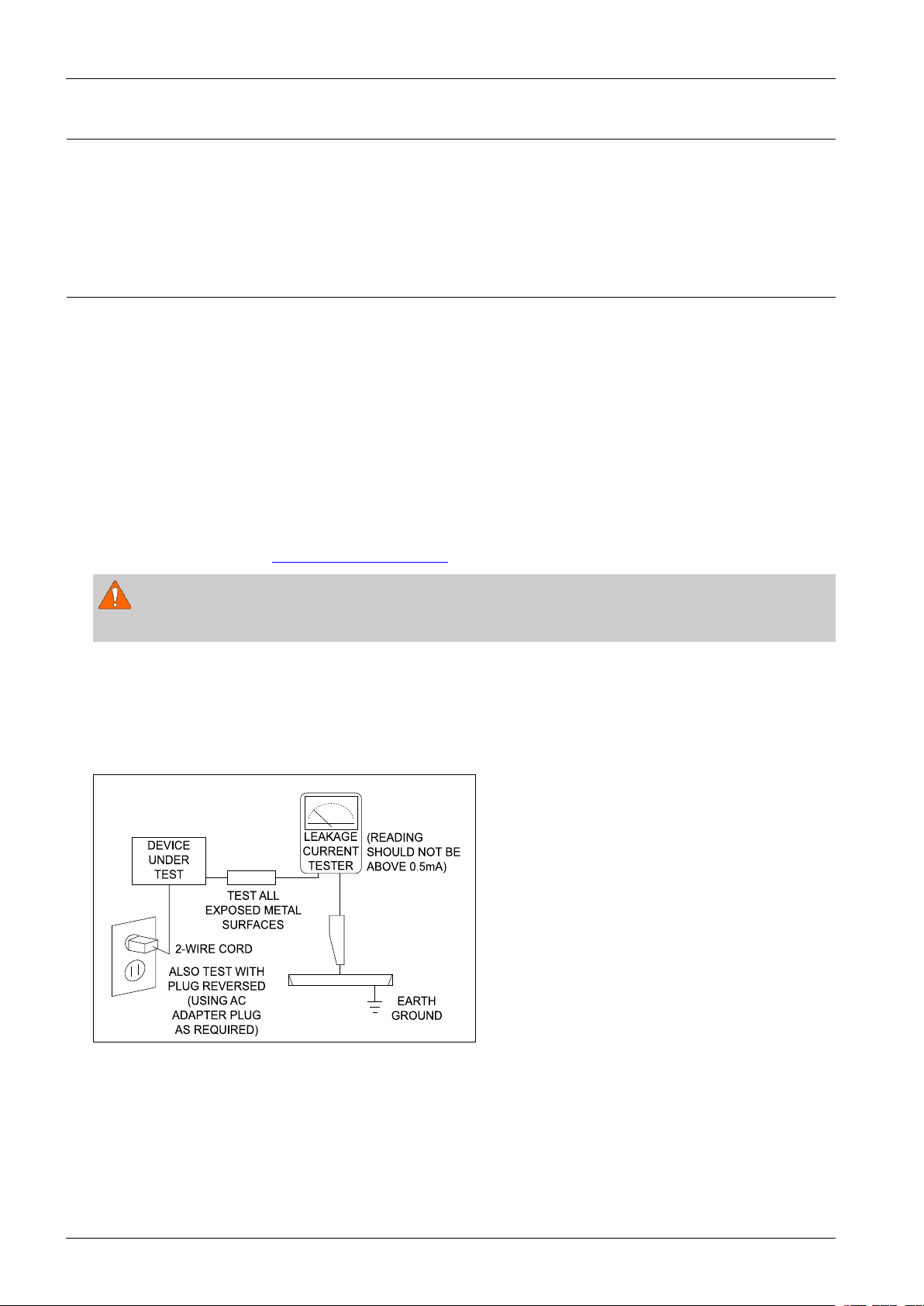
4)LeakageCurrentHotCheckFigure1.1
ACLeakageTest:
WARNING
Donotuseanisolationtransformerduringthistest.Usealeakage-currenttesterorameteringsystemthatcomplies.
Withtheunitcompletelyreassembled,plugtheACcorddirectlyintoaACoutlet.Withtheunit’spowerswitchedfrom
theONtotheOFFposition,measurethecurrentbetweenaknowngroundandallexposedmetalparts.
KnownGrounds-Earth
KnownMetalparts-screwheads,metalcabinets,etc.
Figure1.1ACLeakageT est
1-1Copyright©1995-2013SAMSUNG.Allrightsreserved.
1.Precaution
Ante nna
Term inal
ohm
Expo sed
Meta l Part
Ohmmet er
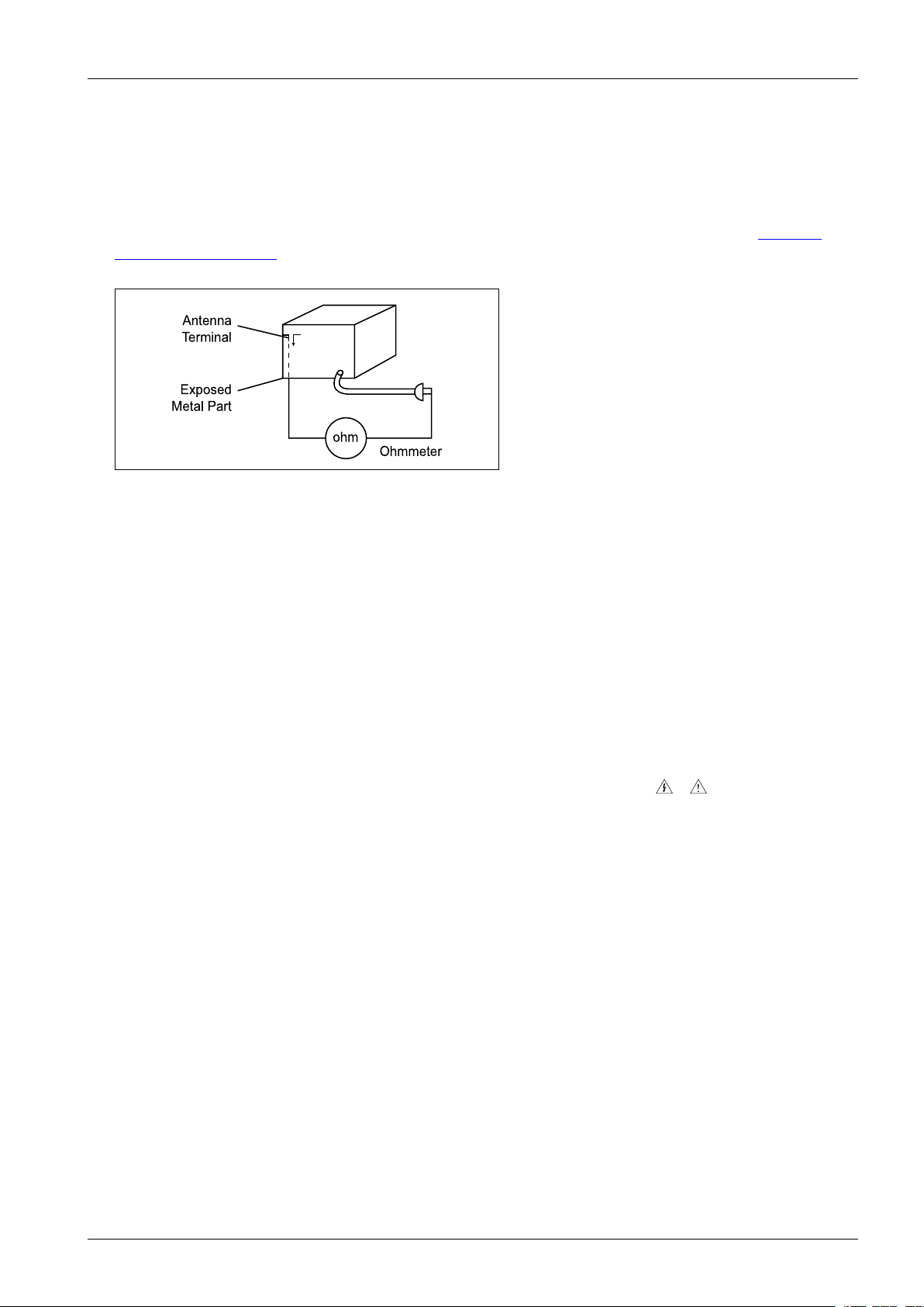
5)InsulationResistanceColdCheck:
(1)Withtheunit’sACplugdisconnectedfromtheACsource,connectanelectricaljumperacrossthetwoACprongs.
(2)SetthepowerswitchtoON.(3)MeasuretheresistancebetweentheshortedACplugandanyexposedmetallicparts.
Example:screwheads,metalcabinets,antennaport,etc.Ifanyoftheexposedmetallicpartshasareturnpathtothe
chassis,themeasuredresistanceshouldbebetween1and5.2megohms.Ifthereisnoreturnpath,themeasured
resistanceshouldbe“innite.”Iftheresistanceisoutsidetheselimits,ashockhazardmightexist.SeeFigure1.2
InsulationResistanceTest
Figure1.2InsulationResistanceTest
6)Components,partsandwiringthatappeartohaveoverheatedorthatareotherwisedamagedshouldbereplacedwith
partsthatmeettheoriginalspecications.Alwaysdeterminethecauseofdamageoroverheating,andcorrectany
potentialhazards.
7)Observetheoriginalleaddress,especiallynearthefollowingareas:Antennawiring,sharpedges,andespeciallytheAC
andhighvoltagepowersupplies.Alwaysinspectforpinched,out-of-place,orfrayedwiring.
Donotchangethespacingbetweencomponentsandtheprintedcircuitboard.ChecktheACpowercordfordamage.
Makesurethatnowiresorcomponentstouchthermallyhotparts.
8)ProductSafetyNotice:
Someelectricalandmechanicalpartshavespecialsafety-relatedcharacteristicswhichmightnotbeobviousfromvisual
inspection.Thesesafetyfeaturesandtheprotectiontheygivemightbelostifthereplacementcomponentdiffersfrom
theoriginal—evenifthereplacementisratedforhighervoltage,wattage,etc.
9)Componentsthatarecriticalforsafetyareindicatedinthecircuitdiagrambyshading,
or.Usereplacement
componentsthathavethesameratings,especiallyforameresistanceanddielectricstrengthspecications.A
replacementpartthatdoesnothavethesamesafetycharacteristicsastheoriginalmightcreateshock,reorother
hazards.
Copyright©1995-2013SAMSUNG.Allrightsreserved.1-2

1.Precaution
1.2.ServicingPrecautions
1)Servicingprecautionsareprintedonthecabinet.Followthem.
2)Alwaysunplugtheunit’sACpowercordfromtheACpowersourcebeforeattemptingto:
(a)Removeorreinstallanycomponentorassembly ,(b)Disconnectanelectricalplugorconnector,(c)Connecta
testcomponentinparallelwithanelectrolyticcapacitor.
3)Somecomponentsareraisedabovetheprintedcircuitboardforsafety.Aninsulationtubeortapeissometimesused.
Theinternalwiringmaybeclampedtopreventcontactwiththermallyhotcomponents.Reinstallallsuchelements
totheiroriginalposition.
4)Afterservicing,alwayscheckthatthescrews,componentsandwiringhavebeencorrectlyreinstalled.Makesurethat
theportionaroundtheservicedparthasnotbeendamaged.
5)ChecktheinsulationbetweenthebladesoftheACplugandaccessibleconductiveparts(examples:metalpanels,
inputterminalsandearphonejacks).
6)InsulationCheckingProcedure:
DisconnectthepowercordfromtheACsource.Connectaninsulationresistancemeter(500V)tothebladesofthe
ACplug.TheinsulationresistancebetweeneachbladeoftheACplugandaccessibleconductiveparts(seeabove)
shouldbegreaterthan1megohm.
7)NeverdefeatanyoftheB+voltageinterlocks.DonotapplyACpowertotheunit(oranyofitsassemblies)unlessall
solid-stateheatsinksarecorrectlyinstalled.
8)Alwaysconnectatestinstrument’sgroundleadtotheinstrumentchassisgroundbeforeconnectingthepositivelead;
alwaysremovetheinstrument’sgroundleadlast.
CAUTION
Firstreadthe“SafetyPrecautions”sectionofthismanual.Ifsomeunforeseencircumstancecreatesaconictbetweenthe
servicingandsafetyprecautions,alwaysfollowthesafetyprecautions.
1-3Copyright©1995-2013SAMSUNG.Allrightsreserved.

1.Precaution
1.3.PrecautionsforElectrostaticallySensitiveDevices(ESDs)
Somesemiconductor(“solidstate”)devicesareeasilydamagedbystaticelectricity.
SuchcomponentsarecalledElectrostaticallySensitiveDevices(ESDs).
Examplesincludeintegratedcircuitsandsomeeld-effecttransistors.
Thefollowingtechniqueswillreducetheoccurrenceofcomponentdamagecausedbystaticelectricity:
1)Immediatelybeforehandlinganysemiconductorcomponentsorassemblies,draintheelectrostaticchargefromyour
bodybytouchingaknownearthground.Alternatively,wearadischargingwrist-strapdevice.(Besuretoremoveit
priortoapplyingpower–thisisanelectricshockprecaution.)
2)AfterremovinganESD-equippedassembly,placeitonaconductivesurfacesuchasaluminumfoiltoprevent
accumulationofelectrostaticcharge.
3)Donotusefreon-propelledchemicals.ThesecangenerateelectricalchargesthatdamageESDs.
4)Useonlyagrounded-tipsolderingironwhensolderingorunsolderingESDs.
5)Useonlyananti-staticsolderremovaldevice.Manysolderremovaldevicesarenotratedas“anti-static”(thesecan
accumulatesufcientelectricalchargetodamageESDs).
6)DonotremoveareplacementESDfromitsprotectivepackageuntilyouarereadytoinstallit.
MostreplacementESDsarepackagedwithleadsthatareelectricallyshortedtogetherbyconductivefoam,aluminum
foilorotherconductivematerials.
7)ImmediatelybeforeremovingtheprotectivematerialfromtheleadsofareplacementESD,touchtheprotectivematerial
tothechassisorcircuitassemblyintowhichthedevicewillbeinstalled.
8)MinimizebodymotionswhenhandlingunpackagedreplacementESDs.Motionssuchasbrushingclothestogether,or
liftingafootfromacarpetedoorcangenerateenoughstaticelectricitytodamageanESD.
Copyright©1995-2013SAMSUNG.Allrightsreserved.1-4

2.ProductSpecication
2.ProductSpecication
2.1.ProductFeature
2.1.1.ProductFeatureMX-F830/MX-F830B
■Power
•2.0ch:1000WTotalRMS/12000WPMPO(Front:500W/chx2)
•IRAmp
■SpecializedFunction
•Bluetooth(OnlyMX-F830B)
•FrontSpeakLEDLighting
•CDRipping(Abletorippingwhilelistening)
•NewBassSoundSystem(CalledGIGASound)
•TwinUSB
■Connectivity
•USBHost
•PortableAudioIn(3.5phiStereoJack)
•MICInput(3.5phiStereoJack)
■Disc
•Type:1Tray
•Compatible:MP3,CD/CD-R,RW,WMA
2-1Copyright©1995-2013SAMSUNG.Allrightsreserved.

2.1.2.ProductFeatureMX-F850
■Power
•2.1ch:1200WTotalRMS/14400WPMPO(Front:400W/chx2,Subwoofer:400W/ch)
•IRAmp
■SpecializedFunction
•FrontSpeakLEDLighting
•CDRipping(Abletorippingwhilelistening)
•NewBassSoundSystem(CalledGIGASound)
•TwinUSB
■Connectivity
•USBHost
•PortableAudioIn(3.5phiStereoJack)
2.ProductSpecication
•MICInput(3.5phiStereoJack)
■Disc
•Type:1Tray
•Compatible:MP3,CD/CD-R,RW,WMA
Copyright©1995-2013SAMSUNG.Allrightsreserved.2-2

2.ProductSpecication
2.1.3.ProductFeatureMX-F870
■Power
•4.2ch:1600WTotalRMS/19200WPMPO(Front:330W/Chx2,Rear:165W/Chx2,W oofer:330W/x2)
•IRAmp
■SpecializedFunction
•FrontSpeakLEDLighting
•CDRipping(Abletorippingwhilelistening)
•NewBassSoundSystem(CalledGIGASound)
•TwinUSB
■Connectivity
•USBHost
•PortableAudioIn(3.5phiStereoJack)
•MICInput(3.5phiStereoJack)
■Disc
•Type:1Tray
•Compatible:MP3,CD/CD-R,RW,WMA
2-3Copyright©1995-2013SAMSUNG.Allrightsreserved.
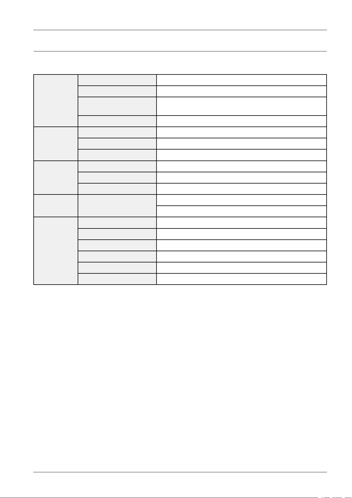
2.2.Specications
■BasicSpecicationMX-F830/MX-F830B
Weight8.60lbs
Dimensions9.17(W)x13.82(H)x11.81(D)inches
General
AMT uner
(optional)
OperatingTemperature
Range
OperatingHumidityRange10%to75%
Signal/Noiseratio55dB
Usablesensitivity12dB FMTuner
Totalharmonicdistortion0.6%
Signal/Noiseratio35dB
Usablesensitivity70dB
Totalharmonicdistortion4%
2.ProductSpecication
+41°F~+95°F
CDDisc
Amplier
CD:12cm
(CompactDisc)
TotalOutputPower1000Watts(MAX)
Frontspeakeroutput500W/CH(6Ω/100Hz)
Frequencyrange20Hz~20KHz
S/NRatio75dB
Channelseparation50dB
Inputsensitivity(AUX)800mV
ReadingSpeed:4.8~5.6m/sec.
MaximumPlayTime:74min.
Copyright©1995-2013SAMSUNG.Allrightsreserved.2-4
2.ProductSpecication
■BasicSpecicationMX-F850/MX-F870
Weight3.9Kg
Dimensions233(W)x351(H)x300(D)mm
General
AMT uner
(optional)
OperatingTemperature
Range
OperatingHumidityRange10%to75%
Signal/Noiseratio55dB
Usablesensitivity12dB FMTuner
Totalharmonicdistortion0.6%
Signal/Noiseratio35dB
Usablesensitivity70dB
Totalharmonicdistortion4%
+5°C~+35°C
CDDisc
Amplier
NOTE
•SamsungElectronicsCo.,Ltdreservestherighttochangethespecicationswithoutnotice.
•Weightanddimensionsareapproximate.
•Designandspecicationsaresubjecttochangewithoutpriornotice.
•ForthepowersupplyandPowerConsumption,refertothelabelattachedtotheproduct.
CD:12cm
(CompactDisc)
ModelMX-F850MX-F870
TotalOutputPower1200W atts(MAX)1650W atts(MAX)
Frontspeakeroutput400W/CH(6Ω/100Hz)330W/CH(6Ω/100Hz)
Rearspeakeroutput
(OnlyF870)
Subwoofer400W(6Ω/100Hz)330W(6Ω/100Hz)
Frequencyrange20Hz~20KHz20Hz~20KHz
S/NRatio75dB75dB
Channelseparation50dB50dB
Inputsensitivity(AUX)800mV(AUX)800mV
ReadingSpeed:4.8~5.6m/sec.
MaximumPlayTime:74min.
-
165W/CH(12Ω/100Hz)
2-5Copyright©1995-2013SAMSUNG.Allrightsreserved.
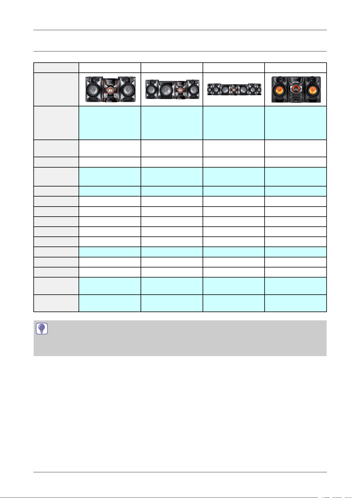
2.3.SpecicationsAnalysis
ModelNameMX-F830/MX-F830BMX-F850MX-F870MX-E63*/MX-E66*
Photo
OUTPUT
POWER
2.0CH1000W2.1CH1200W4.2CH1650W
2.ProductSpecication
MX-E63*:2.0
CH160W
MX-E66*:2.0
CH350W
FRONT
DISPLAY
DIMMEROOOO
Bluetooth
CD/DVDCDCDCDCD/DVD
MP3OOOO
USBHOSTOOOO
CDRIPPINGOOOO
TAPEXXXX
AUDIOINOOOO
HEADPHONEXXXO
FM/RDSFM/AMFM/AMFM/AMFM/AM
REMOTEKEY45KEY45KEY45KEY45KEY
DUAL
VOLTAGE
SPK
IMPENDANCE
VFDVFDVFDVFD
X
(MX-F830BOnly)
XXXO
6Ω6Ω6Ω4Ω
XXX
TIP
O:FeatureIncluded
X:NotIncluded
Copyright©1995-2013SAMSUNG.Allrightsreserved.2-6
2.ProductSpecication
TUNER/AUX
REPEAT
GIGA
REPEAT
A-B
AUTO CHANGE
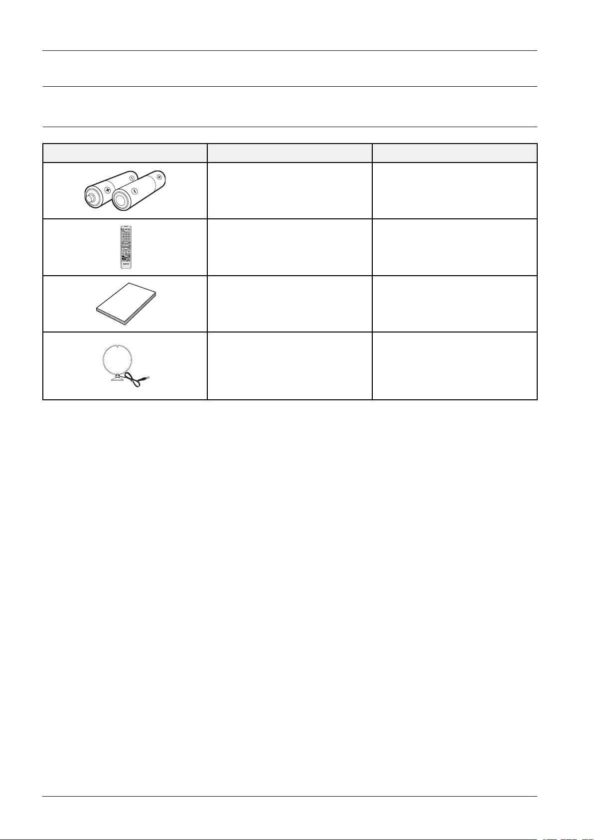
2.4.Accessories
2.4.1.SuppliedAccessories
AccessoriesItemItemcode
Batteries(AAA)4301-000116
RemoteControlAH59-02554A
User’sManualAH68-02606J
FMAntenna
(MX-F830BOnly)
FM/AMAntenna
(MX-F830,MX–F850Only)
AH42-00036A
2-7Copyright©1995-2013SAMSUNG.Allrightsreserved.

3.DisassemblyandReassembly
Lift
3.DisassemblyandReassembly
3.1.MainDisassemblyandReassembly
CAUTION
•Becarefultofollowthedisassemblysequencedescribedinthemanual.Otherwise,theproductmaybedamaged.
•BesuretocarefullyreadandunderstandthesafetyinstructionsbeforeperforminganyworkastheICchipson
thePCBarevulnerabletostaticelectricity.
•Inordertoassemblereversetheorderofdisassembly .
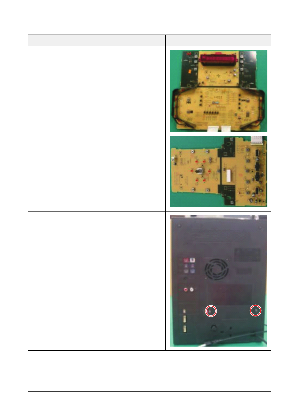
DescriptionDescriptionPhoto
1.FrontKittingAssy
Unfasten2ScrewsoneachSideandV olumeKnob
:BH3*10BLACK
CAUTION
Becarefulnottomakeanyscratchesasyouremovethem.
2.LifttheBottomoftheFrontCovertoSeparateitfromBack
Cover.
Copyright©1995-2013SAMSUNG.Allrightsreserved.3-1
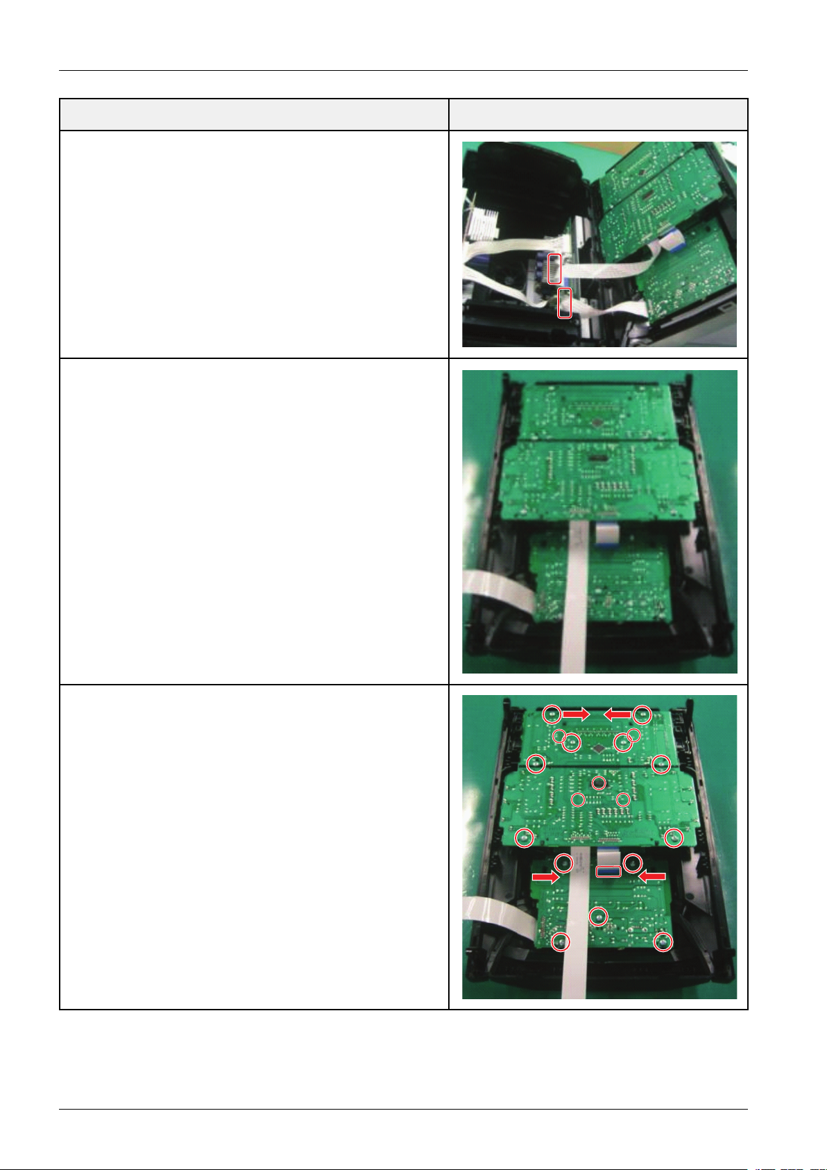
3.DisassemblyandReassembly
3.Unplug2Cables
4.FrontKittingAssy
DescriptionDescriptionPhoto
5.FrontPCBAssy
Unfasten18ScrewsandUnplug1Cable
:BH3*10WHITE
3-2Copyright©1995-2013SAMSUNG.Allrightsreserved.
6.VFDPCB
3.DisassemblyandReassembly
DescriptionDescriptionPhoto
JACKPCB
7.SMPSPCBAssy
Unfasten2Screws
:BH3*10BLACK
Copyright©1995-2013SAMSUNG.Allrightsreserved.3-3
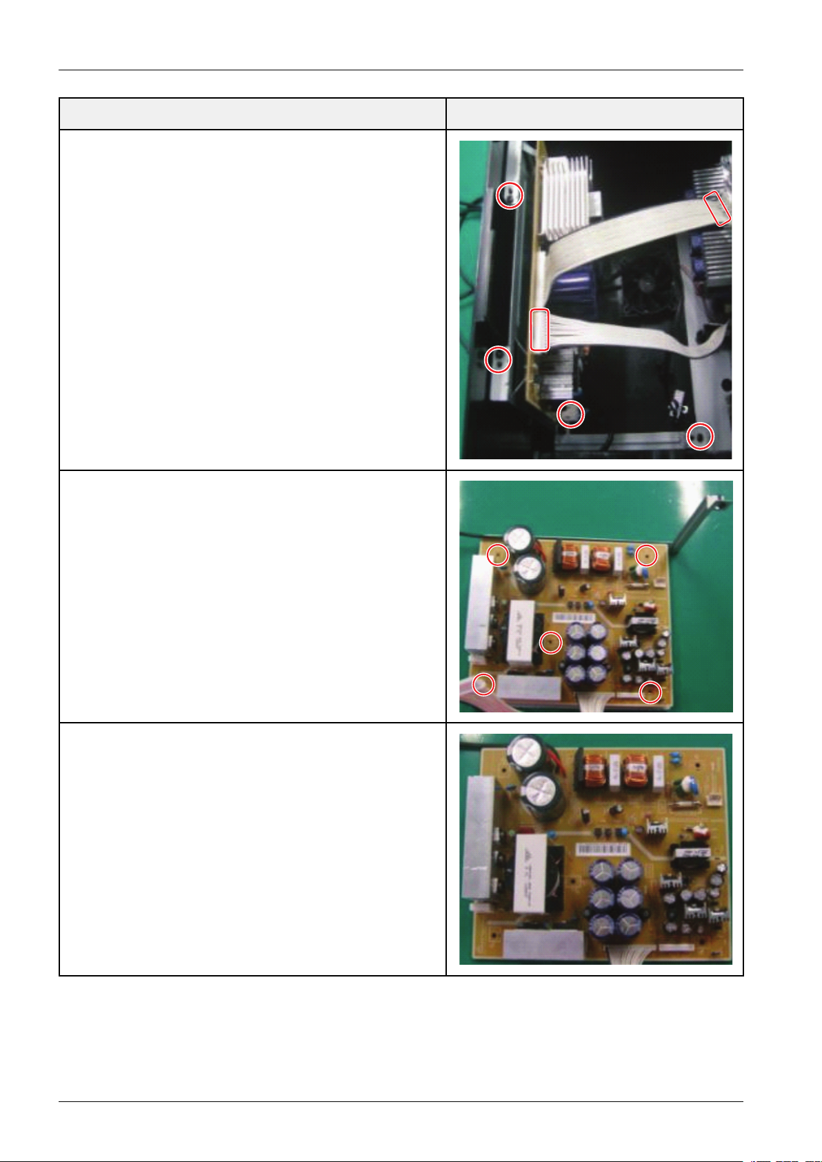
3.DisassemblyandReassembly
DescriptionDescriptionPhoto
8.Unfasten3ScrewsUnplug2wiresandpowercord
:BH3*10BLACK
9.Unfasten5Screws
:BH3*10WHITE
10.SMPSPCBAssy
3-4Copyright©1995-2013SAMSUNG.Allrightsreserved.
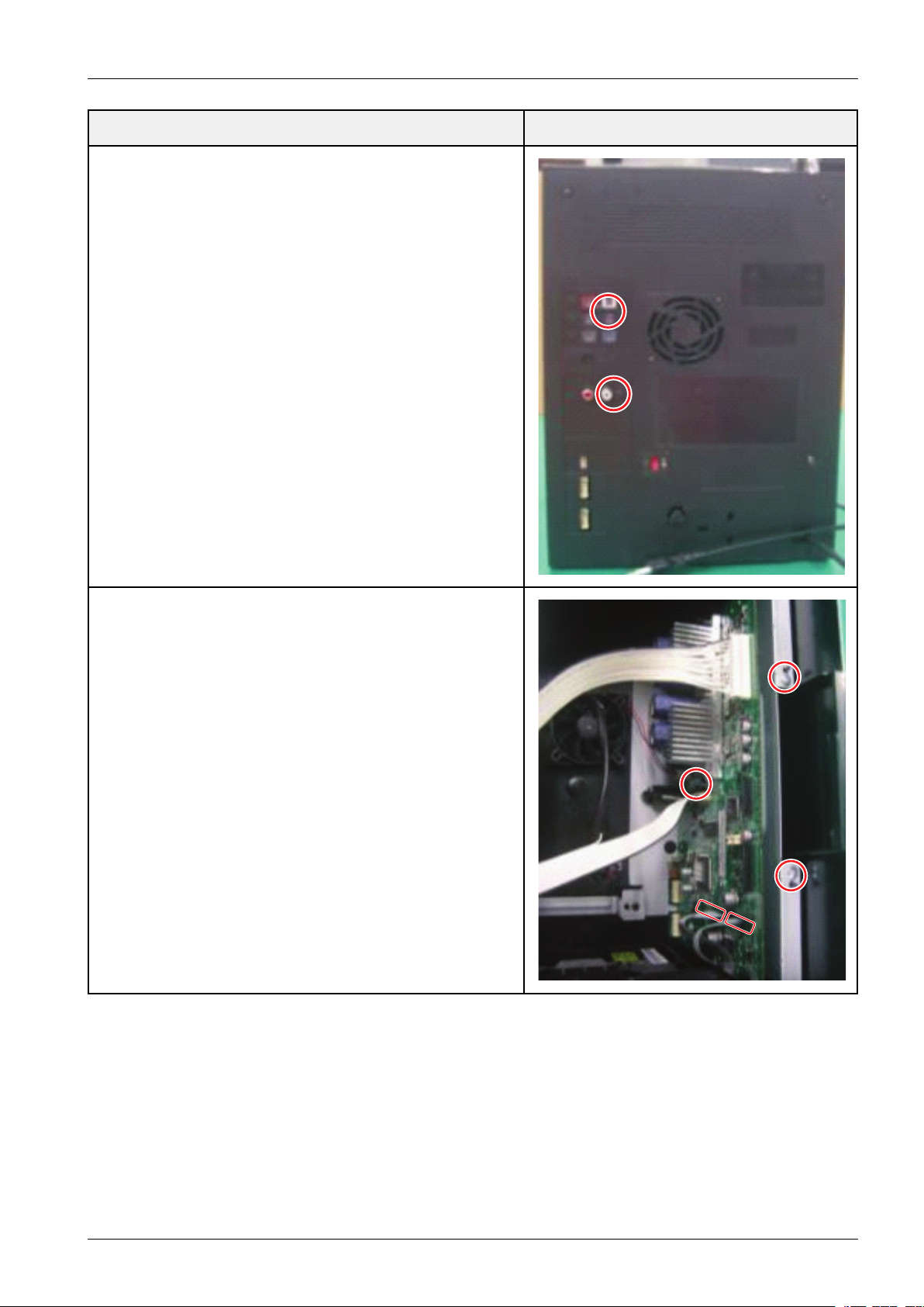
11.MAINPCBAssy
Unfasten2Screws
:BH3*10BLACK
3.DisassemblyandReassembly
DescriptionDescriptionPhoto
12.Unfasten2ScrewsUnplug2CablesandtheF AN
:BH3*10BLACK
Copyright©1995-2013SAMSUNG.Allrightsreserved.3-5
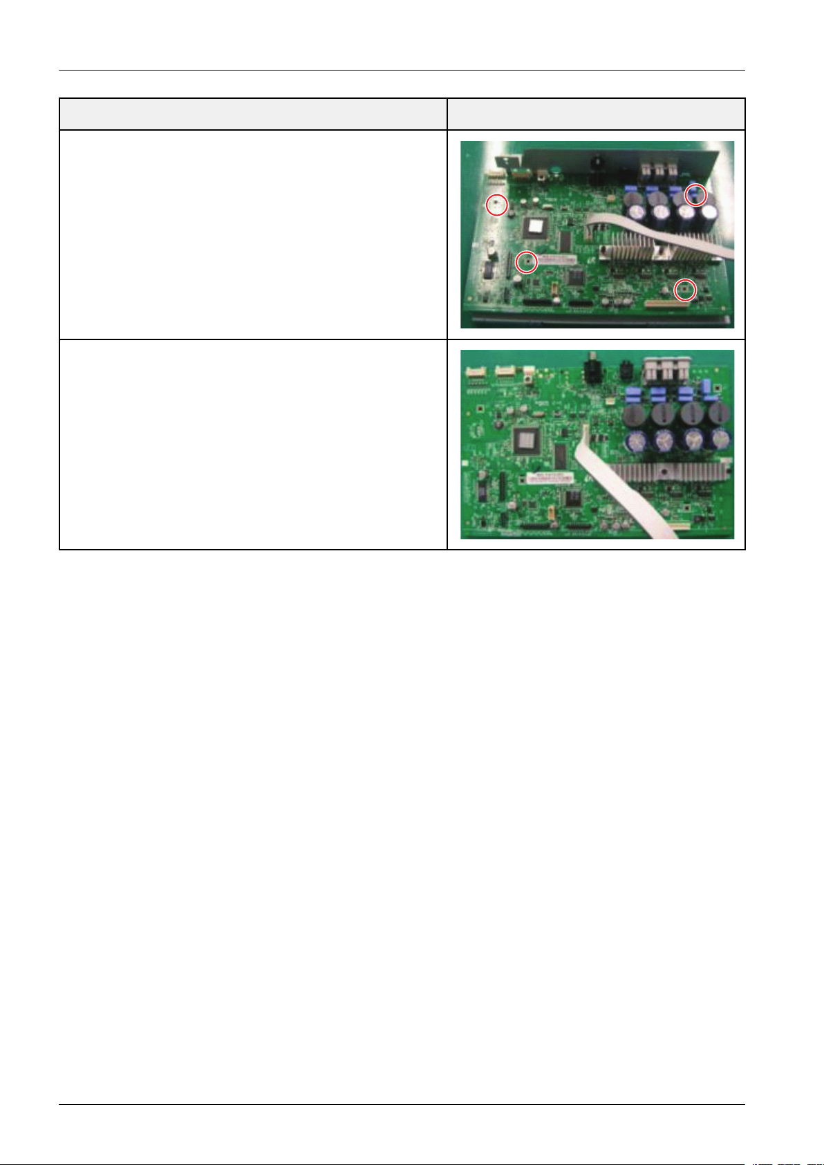
3.DisassemblyandReassembly
13.Unfasten4Screws
:BH3*10SILVER
14.MAINPCBAssy
DescriptionDescriptionPhoto
3-6Copyright©1995-2013SAMSUNG.Allrightsreserved.

4.Troubleshooting
4.1.CheckpointsbyErrorMode
OscilloscopeSettingValuesNormalVoltage24MHz32.768KHz
V oltage/DIV1V ol/DIV1V ol/DIV1Vol/DIV
TIME/DIV1uS/DIV10ns/DIV0.1uS/DIV
4.Troubleshooting
Copyright©1995-2013SAMSUNG.Allrightsreserved.4-1
 Loading...