How it Works
Log In / Sign Up
Buy Points
How it Works
FAQ
Contact Us
Questions and Suggestions
Users
Samsung
Loading...
M
MW87KR
MW87L
5
MW87LPR
MW87LR
MW87LRS
MW87QR
MW87W
7
MW87WR
MW87W-S
MW87Y
3
MW87Y-S
2
MW88
MW880BKA
2
MW880BLA
3
MW880BSA
MW880GRA
3
MW880KSA
MW880RDA
2
MW880RSA
MW888STB
2
MW88L
MW89APSR
MW89AST
3
MW89ASTR
MW89M
7
MW89M-B
2
MW89MPSR
MW89MR
2
MW89M-S
MW89MST
7
MW89MSTR
2
MW89M-W
MW9114ST
MW9114W
MW945WB-XAA
MW949
MW959
MW9596W
10
MW9596WXAX
8
MW959N
MW965
MW965BB
MW965SB
MW965WB
MWR-AH01
4
MWR-BS00
7
MWR-SH00
MWR-TH00
2
MWR-TH01
9
MWR-WE00
MWR-WE10N
4
MWR-WH00
MWR-WS00
MWSM3
MWSM3N
MX-835
MX-C630
MX-C630D
5
MX-C730
MX-C730D
4
MX-C830
4
MX-C830D
4
MX-C850
3
MX-C870
4
MX-D630
MX-D630D
MX-D730
3
MX-D730D
MX-D750
2
MX-D830
MX-D850
2
MX-D870
MX-E630
2
MX-E630D
MX-E650
MX-E650CB-ZA
MX-E650/ZX
2
MX-E661D
MX-E750
MX-E760
MX-E850
MX-E870
MX-F630
MX-F630DB
MX-F730DB
2
MX-F830
2
MX-F850
MX-F870-ZP
MX-FS8000
MX-FS8000-ZA
2
MX-H200RP
MX-H203RP
MX-H204RP
MX-H205RP
MX-H220RP
MX-H630
2
MX-H630-ZA
MX-H630/ZP
MX-H730
2
MX-H835/ZA
Loading...
Loading...
Nothing found
MWR-WE10N
User guide
32 pgs
1.72 Mb
0
Programming Instructions
10 pgs
1.77 Mb
0
installation manual
24 pgs
1.58 Mb
0
Product information
2 pgs
811.34 Kb
0
Table of contents
Loading...
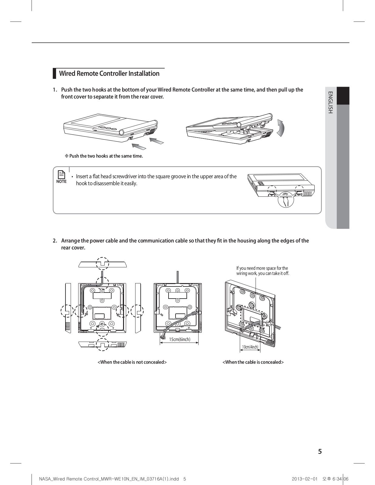
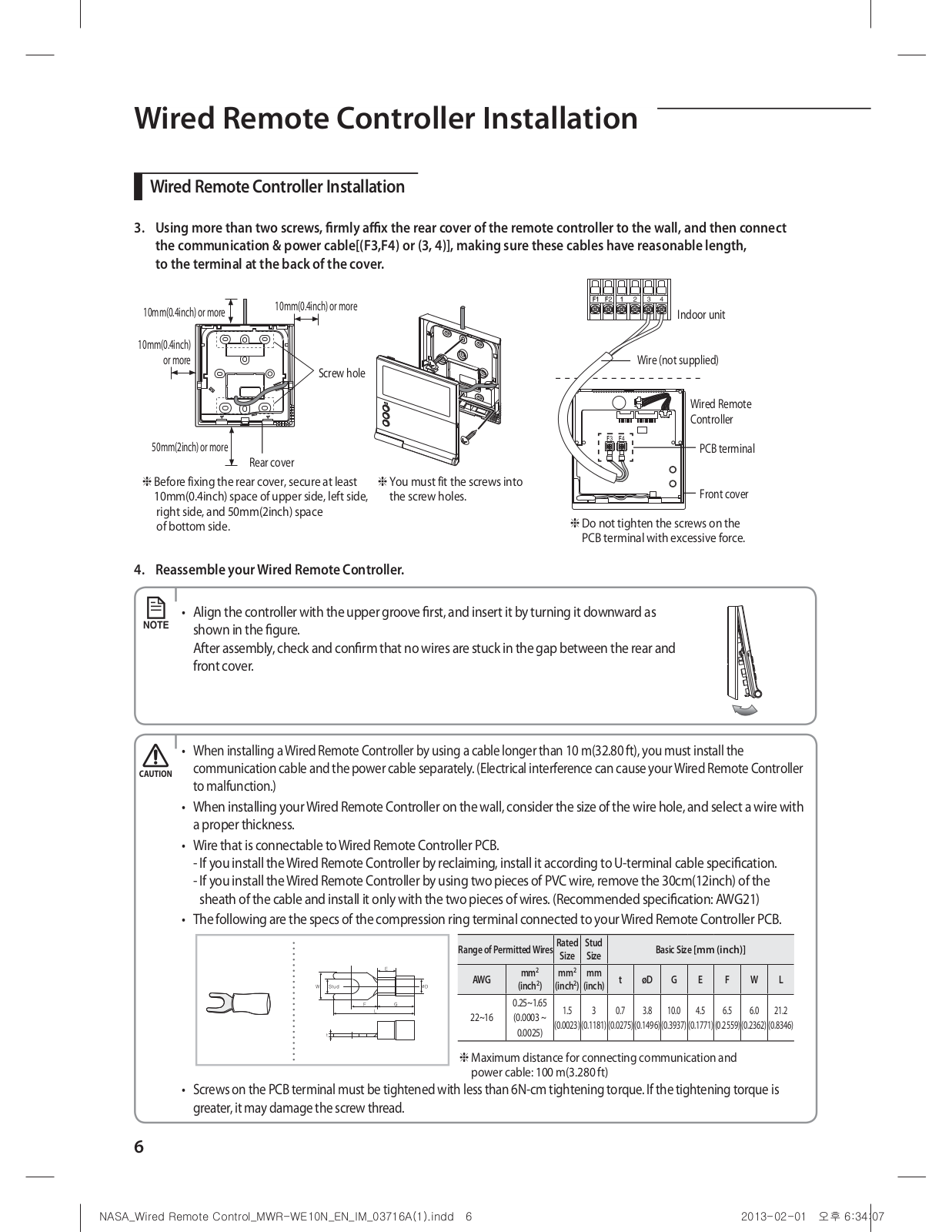
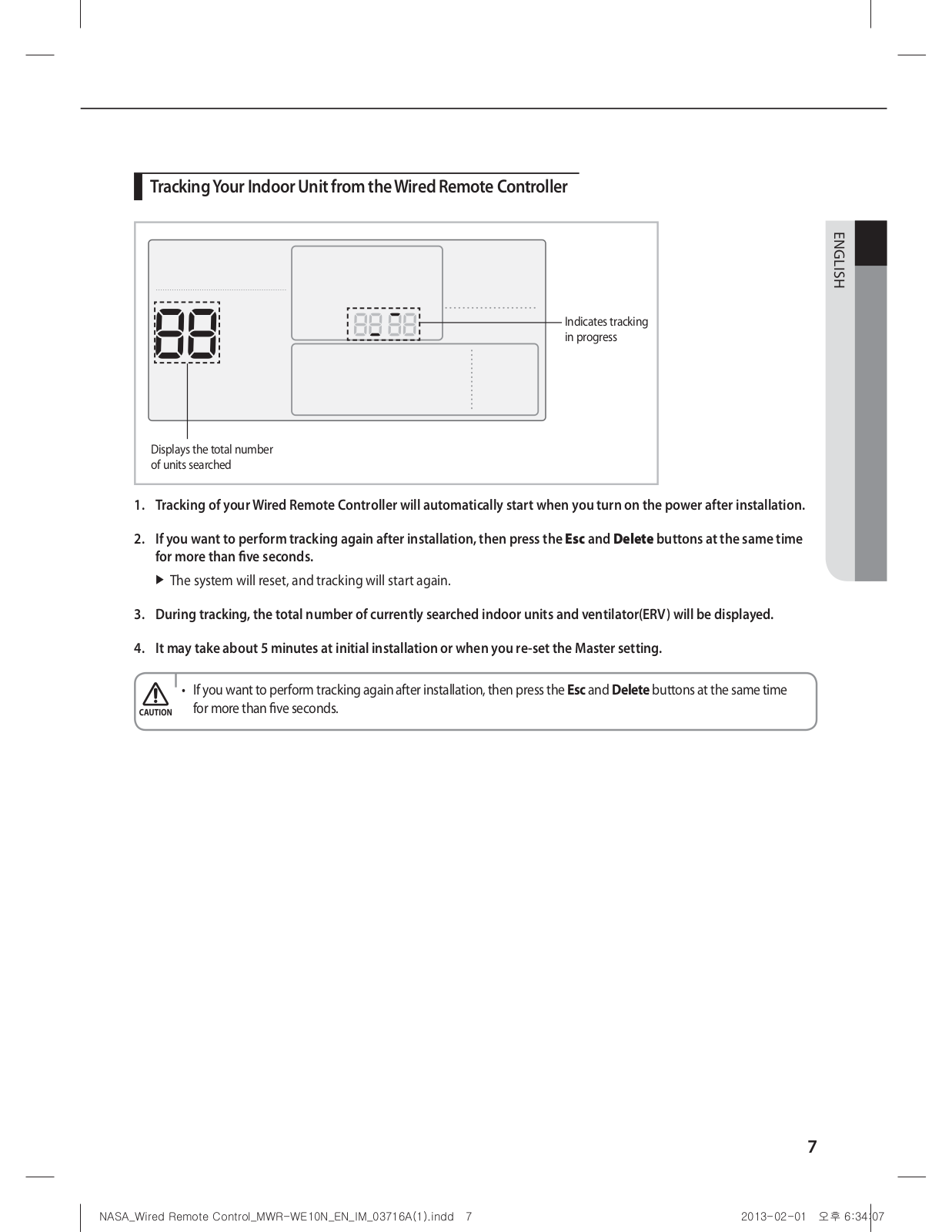
Samsung MWR-WE10N installation manual
...
Samsung installation manual
Download
Specifications and Main Features
Frequently Asked Questions
User Manual
Download
Loading...
+
16
hidden pages
Unhide
You need points to download manuals.
1 point = 1 manual.
You can buy points or you can get point for every manual you upload.
Buy points
Upload your manuals