

4. Alignment and Adjustments
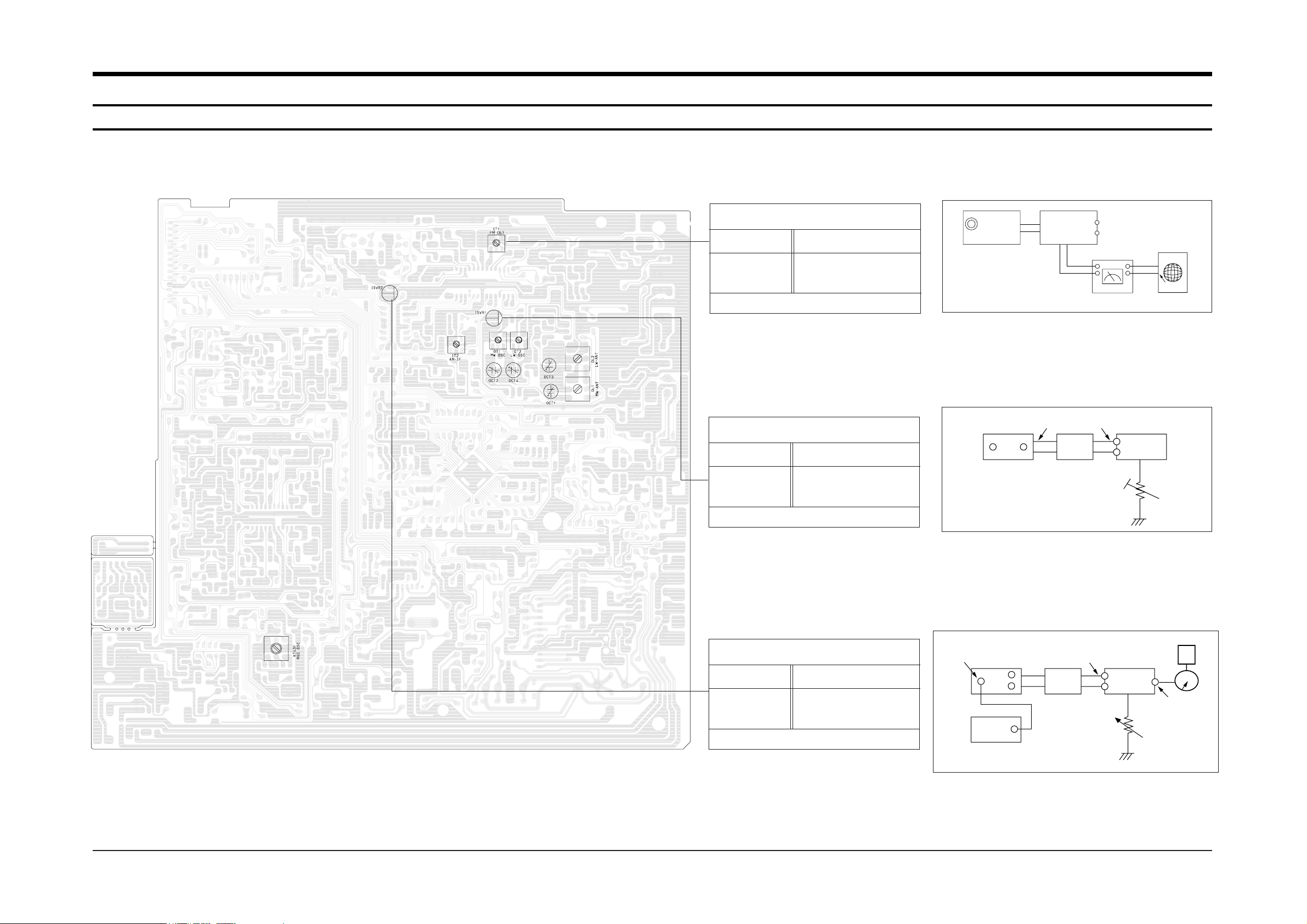
4-1 Tuner
FM T.H.D Adjustment
SSG FREQ. 98MHz
Adjustment
point FM DETECTOR COIL
(IT1)
Minumum output(Figure 4-1)
FM Search Level Adjustment
SSG FREQ. 98MHz
Adjustment
point SEMI-VR(50KB)
(ISVR1)
"TUNED" is shown on LCD(Figure 4-2)
FM
Antenna
Terminal
Speaker
Terminal
Input
Input
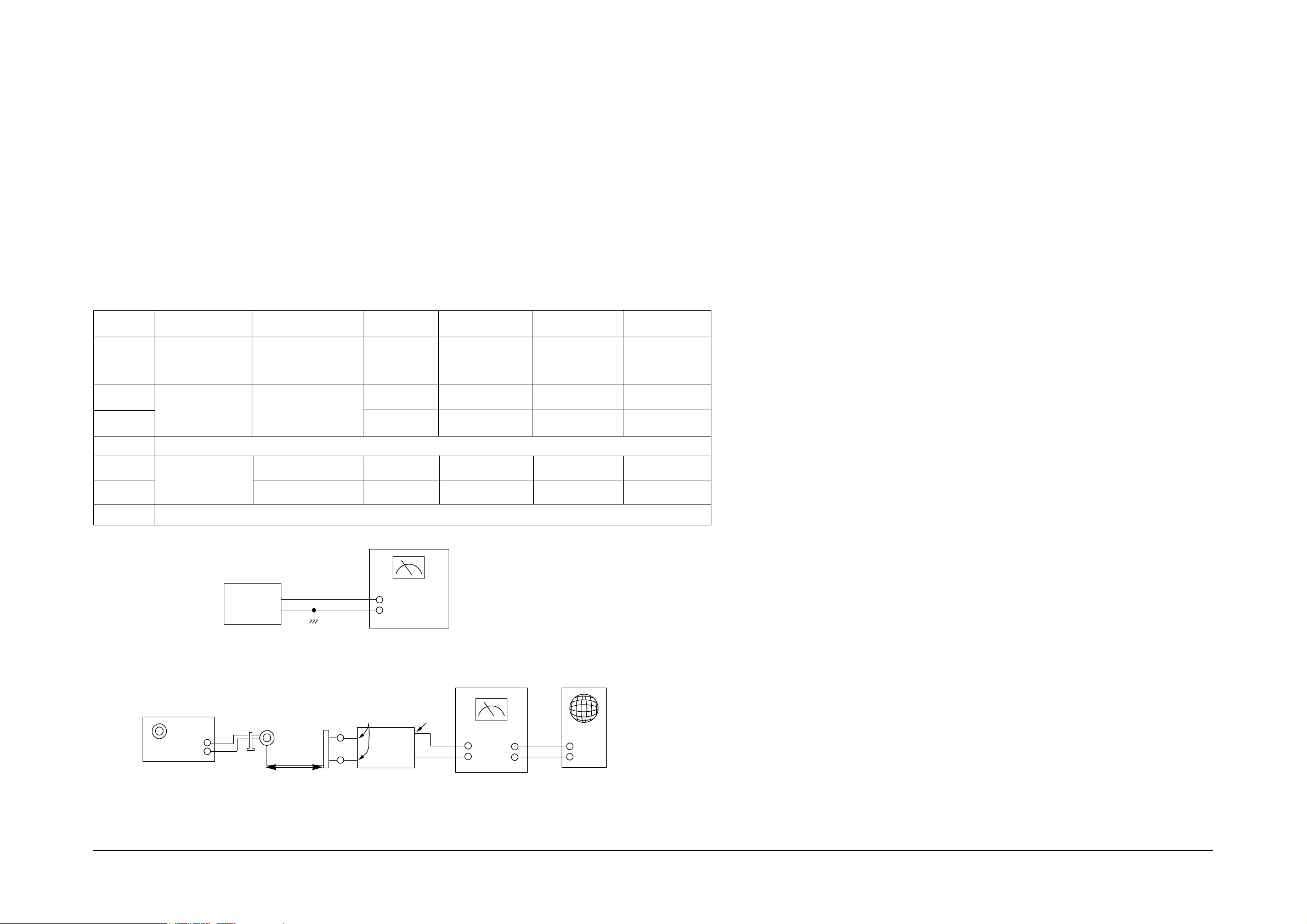
Figure 4-1 IF CENTER and T.H.D Adjustment
Figure 4-2 FM Auto Search Level Adjustment
Output
Distortion Meter
Oscilloscope
Oscilloscope
FM antenna
FM SSG
FM SSG
GND
26dB
75Ω
Dummy
75Ω
Dummy
FM IN
FM Antenna
SET
50 kB
SET
Output
GND
FM Stereo Adjustment
SSG FREQ. 98MHz
Adjustment
point SEMI-VR(5KB)
(ISVR2)
L-CH/R-CH : Maximum(Figure 4-3)
Figure 4-3 FM Stereo Separation Adjustment
EXT
FM
SSG
Stereo
Modulator
(Pilot 10%)
Speaker
terminal
SET
GND
OUT
VTVM
5KB
4-1Samsung Electronics
Samsung Electronics4-2
Step
Item
Connection SSG.FREQ.
FREQ. Setting
Adjust. Point
Remark
Maximum
output
Maximum output
Maximum output
1
Intermediate
frequency (IF)
adjustment
AM frequency
coverage
adjustment
Figure 4-5
Figure 4-4
Connect DC
voltmeter to TCON1
and GND(TP1)
522 KHZ
522 KHZ IT 2
OT 1
OCT 2
OL 1
OCT 1
9V
0.9V
522 KHZ
594 KHZ
1404 KHZ
1611 KHZ
594 KHZ
1404 KHZ
Figure 4-5
_
_
_
Repeat step 2 and 3 serveral times
Repeat step 5 and 6 several times
AM tracking
adjustment
Figure 4-4 AM Frequecny Coverage Adjustment
Figure 4-5 AM Tracking Adjustment
SET
TP2
DC Voltmeter
Input
TP1
AM Signal
Generator
Test Loop
Antenna
AM
Loop Antenna
Jack
Speaker
terminal
GND
Oscilloscope
VTVM
IN
OUT
SET
60 cm
Alignment and Adjustments
2
3
4
5
6
7
4-1-1 Test Equipment
1. AM Standard Signal Generator (S.S.G) : 400Hz, 30% MOD
2. Oscilloscope
3. VTVM
4. Frequency counter
5. Loop antenna
6. Dummy load (4½)
7. DC voltmeter
4-1-2 Pre-Adjustment
1. Check the source voltage.
2. Set function and band switches to the band to be aligned.
3. Set the equalizer, volume and balance controls to mid position.
4-1-3 AM Adjustment

Alignment and Adjustments
Figure 4-6
Figure 4-7
Figure 4-8
4-2-1 Additional Test Equipment : Testing Tape
1. MTT-111 (or equivalent) : Test tape on which 3 KHz signal is recorded (Tape speed adjustment).
2. MTT-113CN (or equivalent) : Test tape on which 8KHz signal is recorded (Azimuth adjustment).
4-2-2 Recording Bias Adjustment
1. Connect frequency counter KC434 and press the REC button.
2. Adjust KT431(Bias OSC Coil) until frequency counter reads 85¡ 0.2KHz.
Item
Connection
Preparation
Tape speed
Figure 4-6
Figure 4-8
3 KHz
SVR
Inside motor
AZIMUTH
(DECK)
adjustment
Maximum output and
identical phase of L,R
channel.
Set the screw
after adjustment.
Insert MTT-111 to
Deck .
Press PLAY button.
Insert MTT-113CN
to Deck .
Press PLAY button.
Figure 4-7
AZIMUTH Adjustment
Screw
REC PB Head
Oscilloscope
IN
OUT
IN
SET
Frequency
Counter
Speaker
Terminal
Speaker
Terminal
Remark
Adjustment point
SET
(GND)
VTVM
V H
4-2 Cassette Deck
Samsung Electronics 4-3
Fixed Screw

Samsung Electronics4-4
4-3 CD
TP2
TP1
Vref
NVR1704
NVR1703 NVR1702
NVR1701
TE CENTER
FE CENTER
E.F BAL
F.BIAS
0V
A
B
A=B
---100mV
---0V
---250mV
---0 V
---100mV
---0 V
---0 V
---0 V
---0 V
4-3-1 To Adjust FOCUS BIAS(STOP mode)
4-3-3 To Adjust Focus Gain (PLAY mode)
4-3-2 To Adjust Tracking Gain (PLAY mode)
4-3-4 To Adjust E/F Balance (PLAY mode)
1. Set Volt/Div of the oscilloscope to DC 100mV.
2. Ground the scope input and set the waveform to 0V, DC range.
3. Connect the GND terminal of the oscilloscope to
Vref, and (+) terminal to center of TP1.
4. Set NVR1701 to 0mV.
1. Connect the GND terminal of the oscilloscope to Vref and (+) terminal to TP2.
2. Load and play the disc
3. While the disc is running adjust the gain with NVR1704 as shown below.
1. Connect the GND terminal of the oscilloscope to Vref and (+) terminal to TP1.
2. Load and play the disc
3. While the disc is running adjust the gain with NVR1703 as shown in the following figure.
VOLT/DIV : 0.2V
TIME/DIV : 2mS
Normal frequency
Normal frequency
Low frequency
High frequency
Low frequency
High frequency
VOLT/DIV : 0.1V
TIME/DIV : 2mS
VOLT/DIV : 0.1V
TIME/DIV : 2mS
VOLT/DIV : 0.1V
TIME/DIV : 2mS
VOLT/DIV : 0.2V
TIME/DIV : 2mS
VOLT/DIV : 0.2V
TIME/DIV : 2mS
1. Set TIME/DIV of the oscilloscope to 2mS.
2. Set Volt/DIV of the oscilloscope to 0.5V.
3. Ground the scope input and set to DC
and then set the DC range.
4. Connect the GND terminal of the oscilloscope to Vref
and (+) terminal to center to TP2.
5. Load and play the disc.
6. Turn NVR1704 counterclockwise to the minimum value.
7. Raise NVR1702 and adjust the waveform so that its middle
comes to GND of the oscilloscope (or until the upper half
of waveform becomes symmetrical to the bottom half, A=B)
8. Adjust NVR1704 (arrow) for normal sound.
Alignment and Adjustments
 Loading...