


5. Troubleshooting
5-1 Print Quality
Error status Check Solution
1. Check HVPS output voltage 1. Refer to HVPS output spec
Dark Image
2. Check terminal contact for - Replace the engine board
HVPS. - Refer to “4 - 11”
2. Fix the terminal to contact well.
1. Check the toner quantity. 1. Replace image cartridge.
Light Image 2. Check HVPS output voltage 2. Refor to HVPS output spec.
3. Check the terminal contact for -Replace the engine board.
HVPS. 3. Fix the terminal to contact well.
1. Compare new image cartridge 1. Replace image cartridge
Horizontal Density with present one
Band. 2. Contamination of Transfer 2. Replace transfer roller
Roller
1. Contamination of Fuser Unit 1. Clean Fuser Unit or change
If not improved, replace it.
2. Contamination of Heat roller 2. Clean Heat Roller
Print Contamination
- Refer to “4-5”
3. Contamination of OPC Drum 3. Clean OPC Drum.
If not improved, replace image
cartridge.
1. Contamination of Fuser Unit 1. Clean Fuser Unit.
If not improved, replace it.
Toner on Backside - Refer to “4-5”
of printer page 2. Contamination of transfer Roller 2. Replace Transfer Roller
3. Contamination fo paper path 3. Remove the contamination on
paper path.
1. Check HVPS output voltage 1. Refer to HVPS output spec
2. OPC Drum contamination or - Replace the engine board
image cartridge life 2. Replace the image cartridge
3. Check the contamination of 3. Clean the lens with a soft
Back Ground
PTL lens dry cloth
4. Check the terminal contact for 4. Fix the terminal to contact well.
HVPS.
5. Check the contamination fo transfer 5. Relpace Transfer Roller
roller.
Vertical Black Streak 1. OPC Drum scar 1. Clean OPC Drum
and band 2. OPC Drum damage 2. Replace image cartridge
Vertical White Streak
1. Contamination of LSU window 1. Clean LSU window
2. If not improved,
replace image cartridge
1. OPC Drum scar or particle 1. Clean OPC Drum & roller
2. Heat roller scar or particle 2. Cleaning heat roller
3. Develope roller scar or particle 3. Clean the develope roller.
Partial Black Image If not improved,
(periodic) replace image cartridge.
4. Charge roller scar or particle 4. Clean the charge roller.
If not improved,
replace image cartridge.
Partial White Image 1. OPC Drum scar or particle 1. Clean OPC Drum
(not periodic) 2. Check the cartridge life 2. Replace image cartridge
Troubleshooting
Samsung Electronics 5-1

Error status Check Solution
1. Check HVPS voltage 1. Refer to HVPS output spec.
- Replace the engine board
2. Check the GND OPC contact. 2. Fix contact points to fit well.
- Contact among GND OPC
contact points.
- Image cartridge.
- GND OPC terminal on frame
- GND OPC terminal on the
No image (all white) engine board
- Confirm the voltage between
GND-OPC and GND-Frame.
: -130V approx
3. Check LSU operation. 3. Replace the LSU.
- Refer to DCU control “05” -Refer to “4-8”
4. Compare new video board 4. Replace the video board.
with present one.
5. Toner empty 5. Replace the image cartridge.
1. Check the charger voltage 1. Refer to HVPS output spec
All Black Image 2. Check the terminal contact - Replace the engine board
3. Compare new video board with 2. Replace terminal
present one 3. Replace video board
Samsung Electronics5-2
Troubleshooting
5-2 HVPS Output Spec
DCU CODE NO. HVPS OUTPUT REMARK
CHARGER “01” - 1.55 KV
TRANSFER “-” “02” -1KV~ -1.4KV
TRANSFER “+” “03” +3.05 KV
BIAS “04” - 475 V
SUPPLY “04” - 675 V
OPC GND _ - 130 V
Troubleshooting
Samsung Electronics 5-3
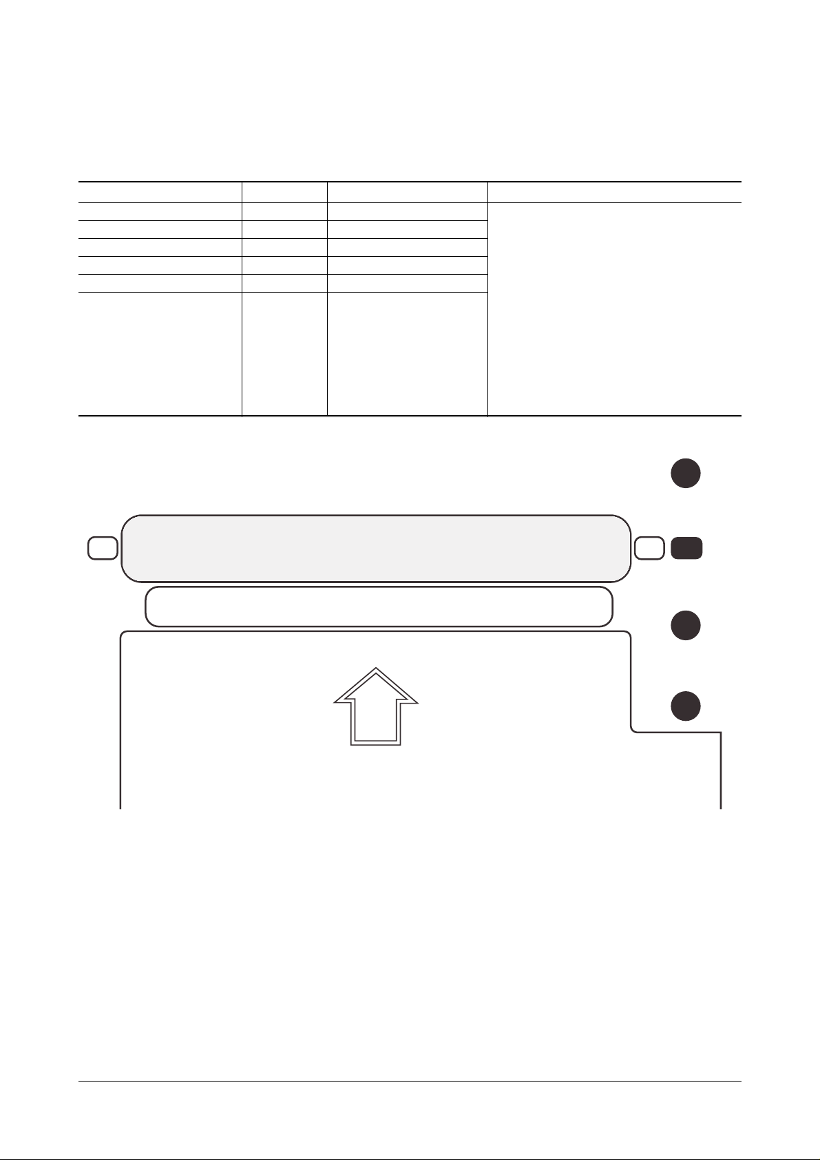
Transfer Roller
P T L (LED-Array)
INSERT IMAGE CARTRIDGE
CHARGER
TRANSFER
BIAS
SUPPLY
1. Turn off the printer
2. Open the rear cover and disassemble
the cover-shield.
3. Connect the DCU on engine board and
close the rear cover.
4. Open the top cover.
5. Remove image Cartridge.
6. Push the Cover Open Switch
7. Select the Diagnostic mode and
measure HVPS output.
*Recommanded Test Equipment
- DVM -High Voltage Probe

5-3 Malfunction
Error status Check Solution
1. Check FUSE 1. Replace SMPS.
- F1(8A), F2(5A) OPEN. - Refer to “4-12”
No Power
2. Check FUSE. 2. Measure the resistance +5V and GND.
- F3(250V/3A) OPEN. (Engine board CN5-pin6 and CN5pin9). If find the short circuit, replace
the Engine board.
1. Check Fuser unit To disassemble the Fuser unit,
- Thermostat open refer to “4-5”.
- hallogen lamp defect 1. If the thermostat of the fuser unit
Normal : 110V version - 2~3Ω is opened. replace it.
220V version - 5~6Ω
2. Check themistor wire assembly defect. 2. If the thermistor wire of the fuser unit
Internal Error 11 Normal : 2~400kΩ is defected, replace it.
(Fuser Error) 3. Check SMPS 3. If the fuser unit is normal,
- CN2 conection on SMPS replace SMPS.
- Fuse(F2) open
- Defect of component related to Fuser
control.
4. Check Engine Board 4. If not normal operation after replacing
- CN7 connection it, replace the engine board.
- Fuser control line:
Cn5-2 level (Lamp on : 0.2V, Lamp off:24V)
Check the Cover Open operation 1. Replace cover open Unit
1. Cover open unit defect -Refer to “4-6”
Cover open 2. Cable damage and connection 2. Replace cover open switch
3. Engine board defect assembly, and connect properly.
3. Replace the engine board.
Samsung Electronics5-4
Troubleshooting

Error status Check Solution
1. Check the exit sensor. 1. Replace Exit sensor.
- Refer to DCU mode “08” - Refer to “4-11”
2. Check the exit sensor actuator. 2. Replace Exit sensor actuator.
Jam 2 3. Check the Exit Roller. - Refer to “4-5, 6-6”
“Paper is stopped 4. Check the Cover Rear. 3. Replace Exit Roller.
just after exit sensor” 5. Check the Contamination of Fuser Unit - Refer to “4-3, 6-1”
4. Replace Cover Rear.
- Refer to “6-1”
5. Replace or Clean Fuser Unit
- Refer to “4-5, 6-6”
1. Check the operation of Duplex Clutch 1. Replace Duplex Clutch.
- Refer to DCU mode “12” - Refer to “4-6”
2. Check the Duplex sensor 1. 2. Replace the DS1 on Engine Board.
- Refer to DCU mode “07” 3. Replace Duplex sensor 1 actuator.
Duplex Jam 1 3. Check the Duplex sensor 1 actuator. - Refer to “4-11”
4. Check the Cover Rear. 4. Replace Cover Rear.
5. Check the bracket duplex unit - Refer to “6-1”
6. Check the duplex solenoid. 5. Replace bracket duplex unit
The resistance of duplex solenoid: - Refer to “6-8”
40~50 ohm. 6. Replace duplex solenoid ass’y.
1. Check the Duplex sensor 2. 1. Replace the DS2 on Engine board.
- Refer to DCU mode “07” 2. Replace Duplex sensor actuator.
Duplex Jam 2 2. Check the Duplex sensor 2 actuator. 3. Replace Gear of shield pcb
3. Check the Gear of shield pcb - Refer to “4-11, 6-7”
- Check all the gear for correct installation
1. Check the LED Array. 1. Replace LED Array.
PTL Error
2. Check the cable connection or wire defect. - Refer to “6-2”
(Pre Transfer Lamp)
3. Check Joint board. 2. Replace harness or reconnection.
3. Replace Joint board.
- Refer to Disassembly
1. Check image cartridge life 1. Replace image cartridge.
2. Check Toner sensor contact. 2. Replace harness or reconnection.
Toner Empty 3. Check Joint board 3. Replace Joint board.
4. Compare new image with present on. - Refer to “4-4”
4. Replace image cartridge.
1. Check OUT-BIN sensor. 1. Replace OUT-BIN sensor.
- Refer to DCU mode “09” 2. Replace OUT-BIN sensor
OUT-BIN Full 2. Check OUT-BIN sensor actuator. actuator.
3. Check cable connection or wire defect 3. Connect the cable correctly or replace
the cable.
1. Check the Cable between Engine and 1. Connect the cable correctly or
Internal Error 20
Video controller. replace the cable.
(Engine Error)
(Engine board CN10 Video controller - Refer to “4-4”
board J11.) 2. Replace Engine board.
2. Engine board defect.
Troubleshooting
Samsung Electronics 5-5

Error status Check Solution
1. Check the DC supply for laser 1. If +5Vs for laser diode isn’t supplied.
scanning unit check the cover switch assembly for
+5Vs and fix it,
Internal Error 10 2. Check laser scanning unit 2. If the DC power supply for laser
(Scanner Error) - Refer to DCU mode “05” scanning unit has normal operation,
replace the laser scanning unit
3. Check the cable connection and defect 3. Replace cable and connect properly.
4. Engine board. 4. If not normal operation after replacing
it, replace the engine board.
1. 1st cassette feeding
1) Check the operation of Pick-up Clutch 1. Replace the Pick-up solenoid on
- Refer to DCU mode “06” Engine Board.
- Refer to “4-11”
2) Check PAD of Pickup roller. 2. Replace PAD.
- Refer to “4-7, 6-5”
3) Check the Gear of Pickup Unit. 3. Replace Pickup Unit Gear.
- Refer to “4-7, 6-5”
4) Check paper installation in cassette 4. Install paper properly.
2. Multi purpose feeding
1) Check the operation of 1. Replace MP solenoid.
multi purpose Clutch If not normal operation after replacing
- Refer to DCU mode “13” it, replace the engine board.
Jam 0 - Check MP solenoid. - Refer to “4-11”.
1. Paper is not The resistance of MP solenoid 70~80Ω 2. Replace PAD
exitted from cassette 2) Check PAD of Pickup roller - Refer to “4-9, 6-4”
3) Check Joint board 3. Replace Joint board.
2. Paper is stopped Measure the CN503-2pin - Refer to “4-4”
before feed sensor. 4) Check the Gear of multi Purpose 4. Replace Pickup Unit Gear.
Pickup Unit 5. Connect the cable correctly
5) Check cable connection or wire defect. or replace the cable.
3. Second cassette feeding
1) Check Pickup Clutch for SCF. 1. Replace the pick-up clutch for SCF.
- The resistance of SCF solenoid: 70~80Ω If not improved, replace SCF board
2) Check PAD of Pickup roller 2. Replace PAD.
3) Check the Gear of pickup Unit - Refer to “6-11”
4) Check paper installation in cassette. 3. Replace Pickup Unit Gear.
5) Check cable connection or wire defect. - Refer to “6-11”
4. Reinstiall paper properly.
5. Connect the cable correctly, or
replace the cable.
1. Check the Feed sensor. 1. Replace Feed Sensor.
Jam 1 - Refer to DCU mode “08” - Refer to “4-11”
“Paper is stopped 2. Check the Feed Sensor actuator 2. Replace Feed Sensor actuator.
on feed sensor” 3. Check the paper installation in - Refer to “4-11, 6-2”
cassette. 3. Reinstall paper properly.
Samsung Electronics5-6
Troubleshooting
 Loading...