

Samsung ML-7000 Disassemble
4. Disassembly
°‹
°‹
°‹
°‹
°‹
°‹
°‹
°‹
°‹
Controller
Cassette
Power Inlet
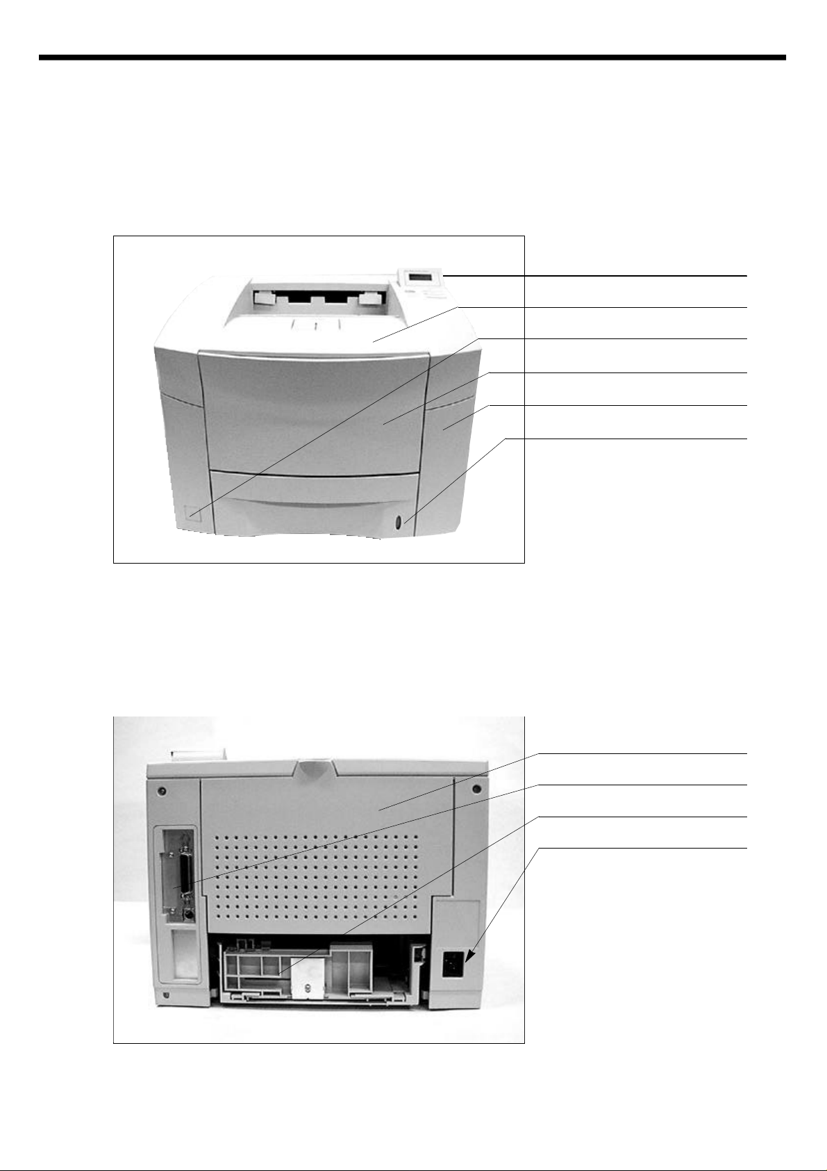
4-1 Front View
Control Panel
Cover Open
Power Switch
Cover Tray
Cover Front
Paper Level Indicator
4-2 Rear View
Cover Rear
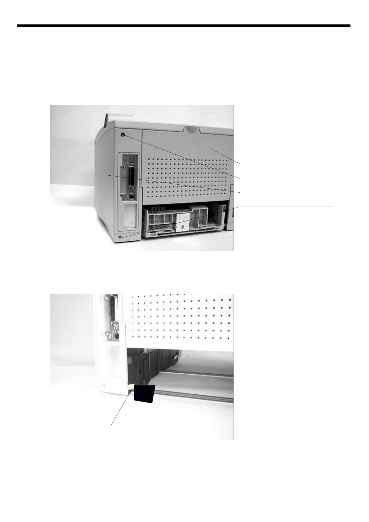
4-3 Cabinet Disassembly
°‹
°‹
Screw
Cover Rear
Cover Right
Screw
Hook
4-3-1. Cover Right
Remove the screws and open the
Cover Rear.
In order to remove the Cover Right.
Please see the hook which locks
the cabinet to the frame, right hand
should first grab the hook and pull it
out for releasing the hook from the
frame.
The left hand should slide the
Cover Right to the backward.
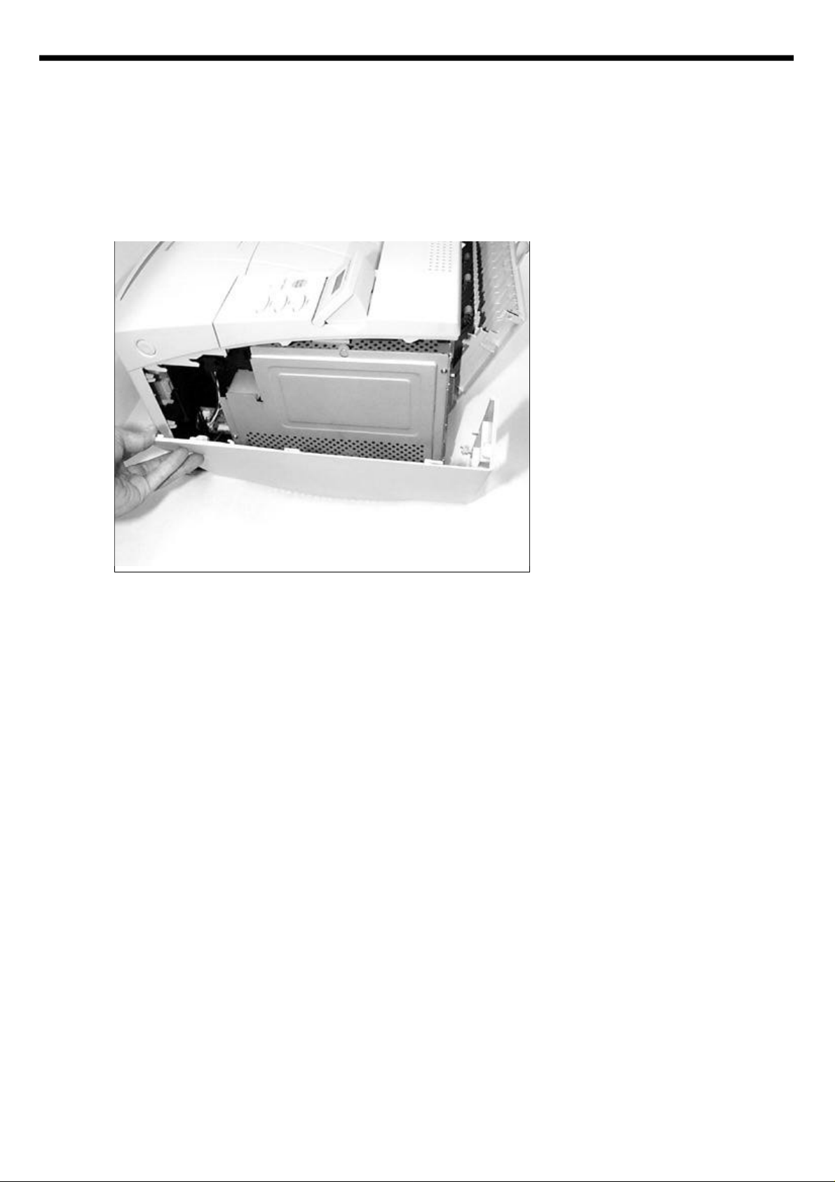
4-3-2. Cover Left
Hook
Hook
Screw
Remove screw and open the Cover
Rear.
Please see the hook of the Cover
Left. Pull the Hook and release it
from the frame.
Pull
Slide the Cover Left to the
backward with pulling the hook out.
The Cover Left can be easily
removed.
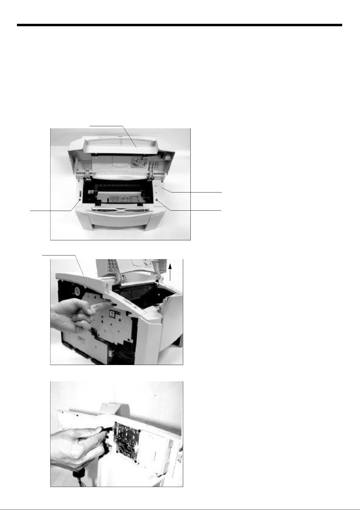
4-3-3. Cover Front
Please see the MP tray disassembly. (4-9)
4-3-4. Cover Main
Cover Open
Open the Cover Open.
Remove two screws.
Cover Top
Screw
Cover Main
Up
Screw
See the hooks.
Push the hooks up and pull them
upward.
With holding Cover Main, remove
the panel wire.
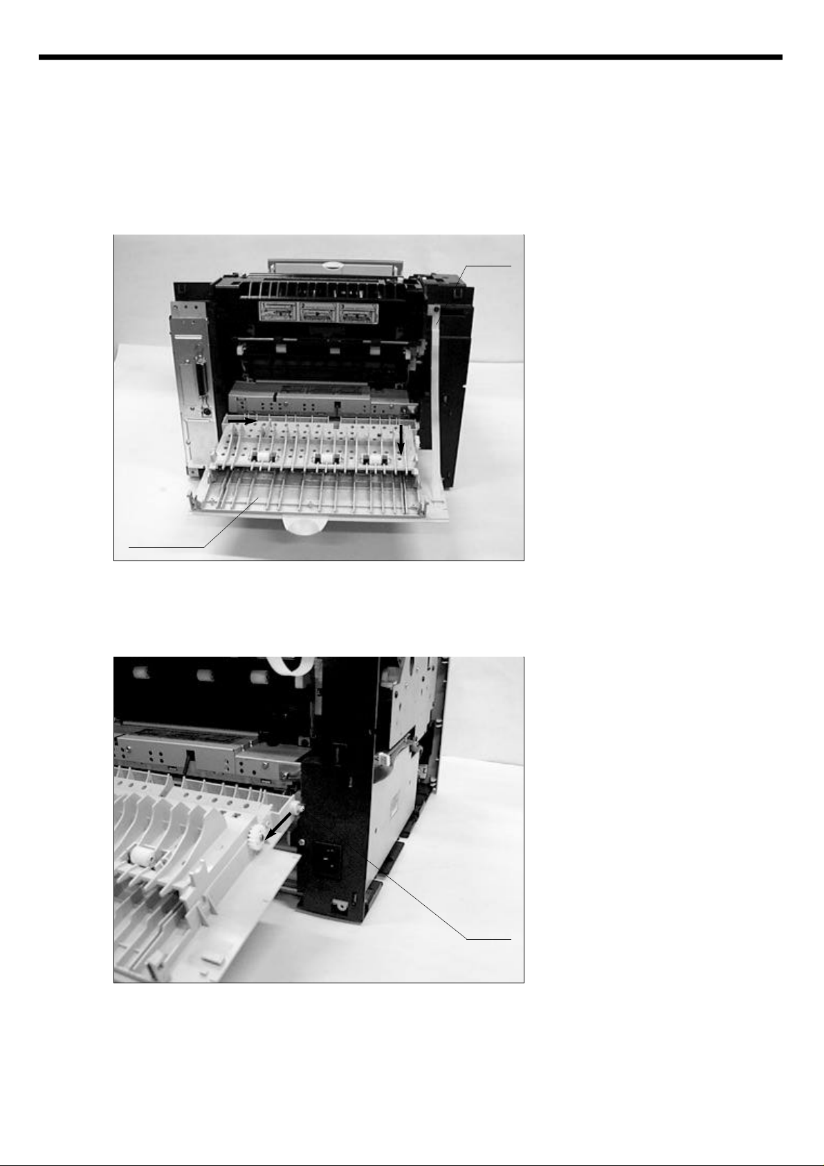
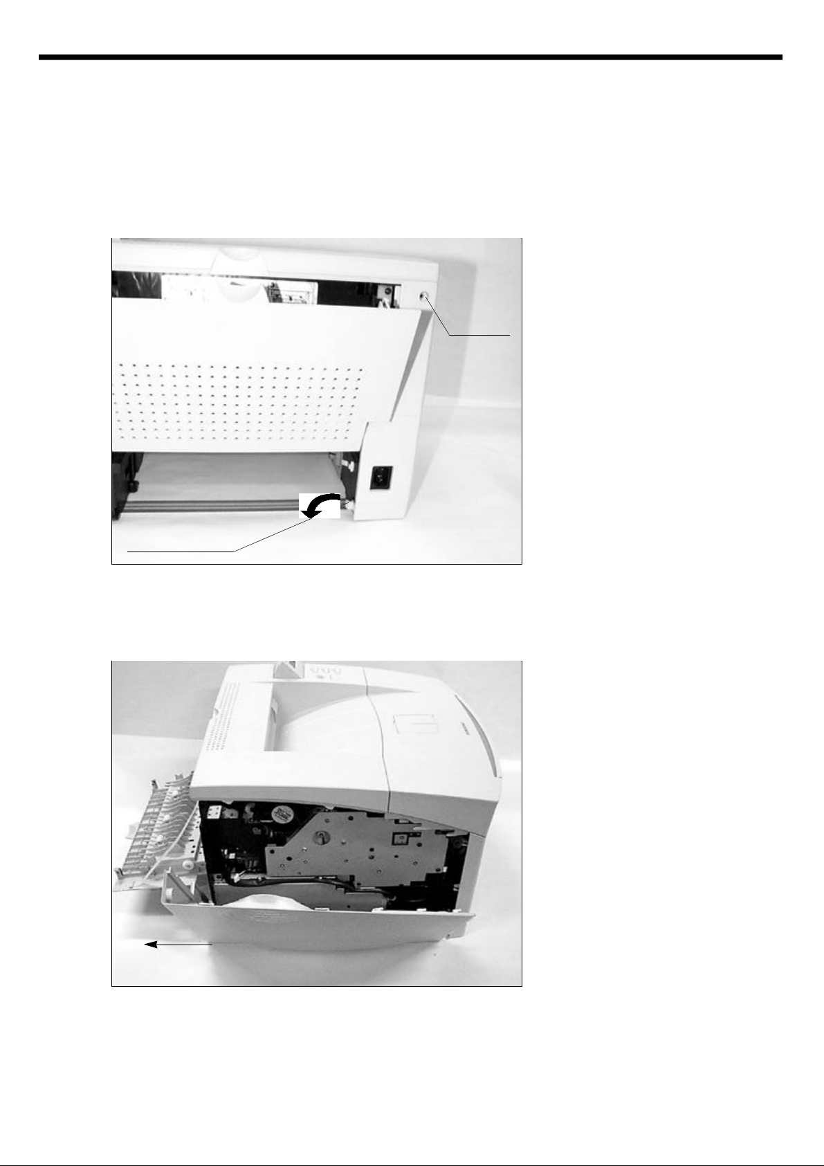
4-3-5. Cover Rear
®Ë
®Á
Cover Rear
Stripe
Open the Cover Rear.
Detach the stripe by pushing the
stripe.
There is a hook holding the stripe.
Hinge
After detaching the stripe from the
Cover Rear,
Release the Cover Rear from the
hinge.
4-4 Video Controller board & Joint board
°‹
After removing external cabinet,
see the 5 screws and you should
remove them.
The Shield ICU is important for EMI
and protection for Controller.
Shield ICU
Joint Board
Screw
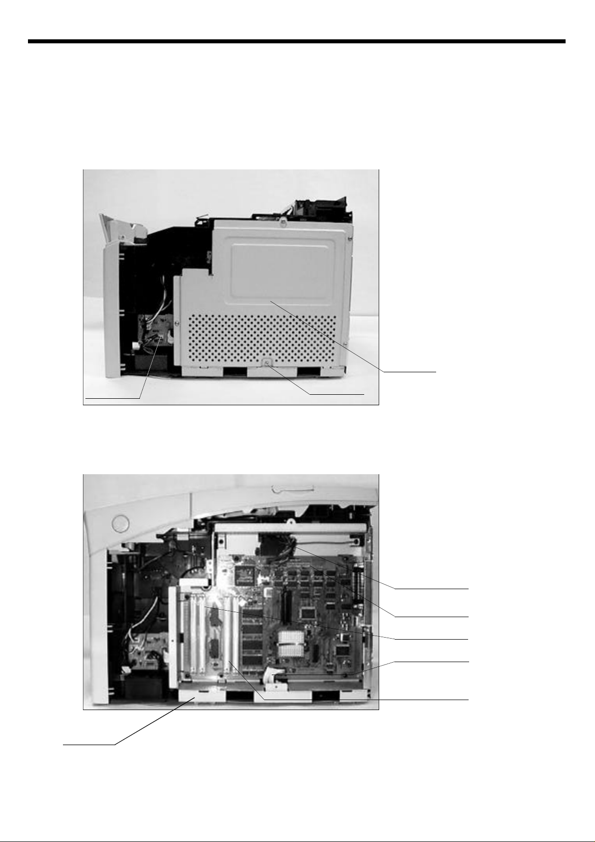
After removing Shield ICU, you can
see the assembled controller.
Unplug the panel cable and engine
I/F cable with care and remove the
screws from the frame.
Panel Cable
Controller
Board
RAM Simm Socket
Engins I/F cable
Flash SIMM or
Postscript SiMM
Socket
Frame ICU
Screw
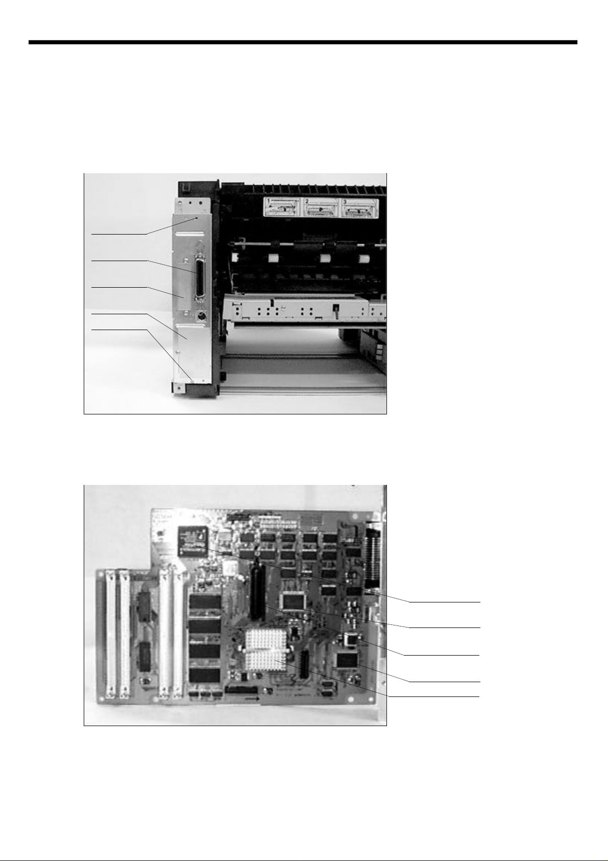
Parallel
I/F
reserved for
Network
reserved for
Serial
Screw
Remove the screws which hold the
Bracket ICU to the frame and detach controller from the frame.
You can see the Frame ICU.
Video Controller Board
ASIC(QP1700)
ASIC
(Powerbridge)
Connector for
Network
ASIC
(Hype chip)
Power PC processor
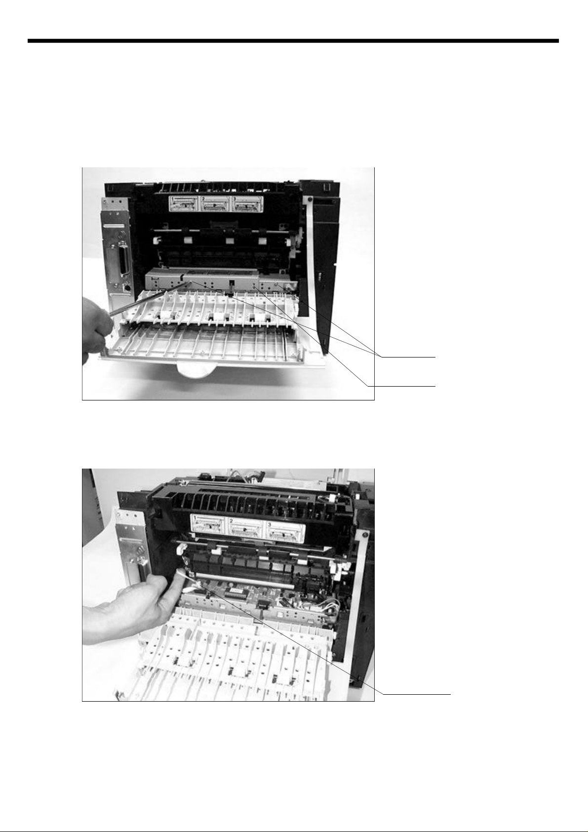
4-5 Fuser Ass’y
Open the Cover Rear and see the
screws and unscrew and remove
the Cover pcb.
Screw
Cover pcb
for engine B’d
After removing the Cover pcb,
unplug the Thermistor connetor
from the Engine Board.
Thermistor
connector
 Loading...