

Page 1
LASER PRINTER
ML-2500 Series
ML-25 10/XAA
Basic Model :ML-2571N
Manual
SERVICE
LASER PRINTER
- Speed : 25ppm (Ltr) / 24ppm(A4), 600dpi
- Paper Path : MPF Type Cassette
- Emulation : SPL (ML-2510)
PCL (ML-2570/ML-2571N)
- Processor : 150MHz Jupiter4e CPU
400MHz SPGP V
- Memory : ML-2510(SDRAM, 8MB),
ML-2570/2571N(SDRAM, 32MB)
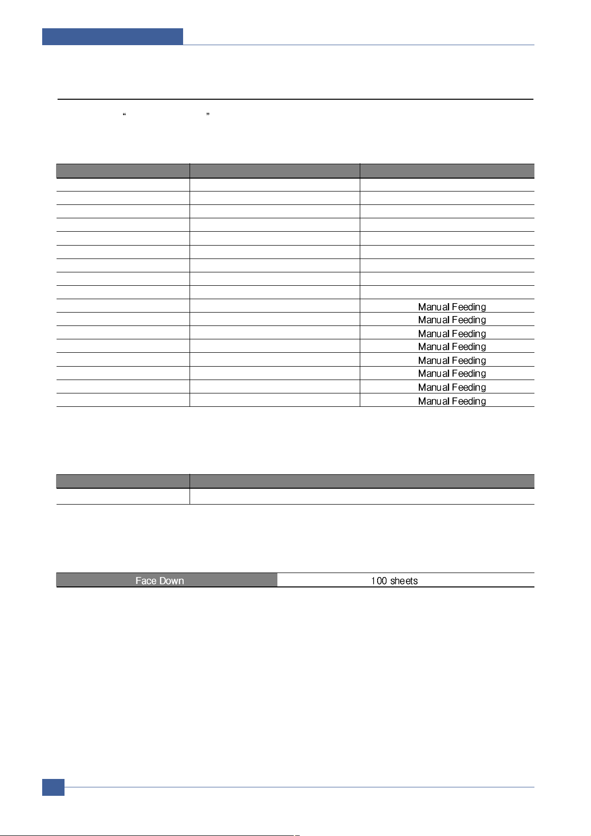
- MP Cassette : 250 pages / Face Down
(100 pages)
- Fuser Design : Lamp Type
The keynote of Product
3 CPU
ML-2571N
- I/O : ML-2510(USB1.1+IEEE 1284),
ML-2570/2571N(USB2.0+IEEE 1284)
- Machine Life : 50K(pages)
Page 2

Contents
1. Precautions
1.1 Safety Warning 1-1
1.2 Safety Caution
1-2
1.3 ESD Precautions
1-4
2. Product Specification
2.1 Product Overview 2-1
2.2 Specifications
2-1
2.3 Model Comparison Table
2-5
2.4 ACCESSORY
2-5
3. System Overview
3.1 System Outline 3-1
3.2 H/W Structure and Descriptions
3-7
3.3 S/W Structure and Descriptions
3-23
3.4 Initial Product Installation
3-27
4. Alignment and Adjustments
4.1 Sample Pattern 4-1
4.2 Control Panel
4-2
4.3 Consumables and Replacement Parts
4-4
4.4 Periodic Defective Image
4-5
4.5 How to use DCU
4-6
4.6 Paper Path
4-1 1
Page 3

5. Disassembly and Reassembly
5.1 General Precautions on Disassembly 5-1
5.2 Disassembly and Reassembly
5-2
6. Troubleshooting
6.1 Checking Symptoms 6-1
6.2 Bad discharge
6-4
6.3 Malfunction
6-8
6.4 Bad software environment
6-13
6.5 Bad Image
6-17
7. Exploded Views & Parts List
7.1 Exploded Views and Parts List 7-1
8. Block diagram
8.1 ML-2510 H/W Block Diagram 8-1
8.2 ML-2570/2571N H/W Block Diagram
8-2
9. Connection Diagram
9.1 ML-2510 Connection Diagram 9-1
9.2 ML-2570/2571N Connection Diagram
9-2
10. Schematic Diagram
10.1 PCL_Main Board 10-1
10.2 GDI_Main Board
10-6
10.3 Connector Circuit Diagram
10-17
10.4 SMPS Circuit Diagram
10-18
10.5 HVPS Circuit Diagram(1/3)
10-19
Continued
Page 4

1 1. Reference Information
1 1 .1 T roubleshooting Tools 11-1
1 1 .2 Acronyms and Abbreviations
11-2
1 1 .3 Selecting printer locations
11-4
1 1 .4 Sample Tests Patterns
11-5
12. Circuit Description
12.1 Engine Controller 12-1
Continued
Page 5
Precautions
Samsung Electronics
Service Manual
1-1
1
1. Precautions
The cautions below are items needed to keep in mind when maintaining and servicing.
Please read carefully and keep the contents in mind to prevent accidents while servicing and to prevent the
machine from getting damaged.
1.1 Safety Warning
(1) Request service by qualified service person.
Service for this machine must be performed by a Qualified service person. It is dangerous if unqualified service personnel or users try to fix the machine.
(2) Do not rebuild.
Do not attach or change parts discretionary. Do not dissemble, fix of rebuilt it. If so, printer will abnormally
work and electric shock or fire may occur.
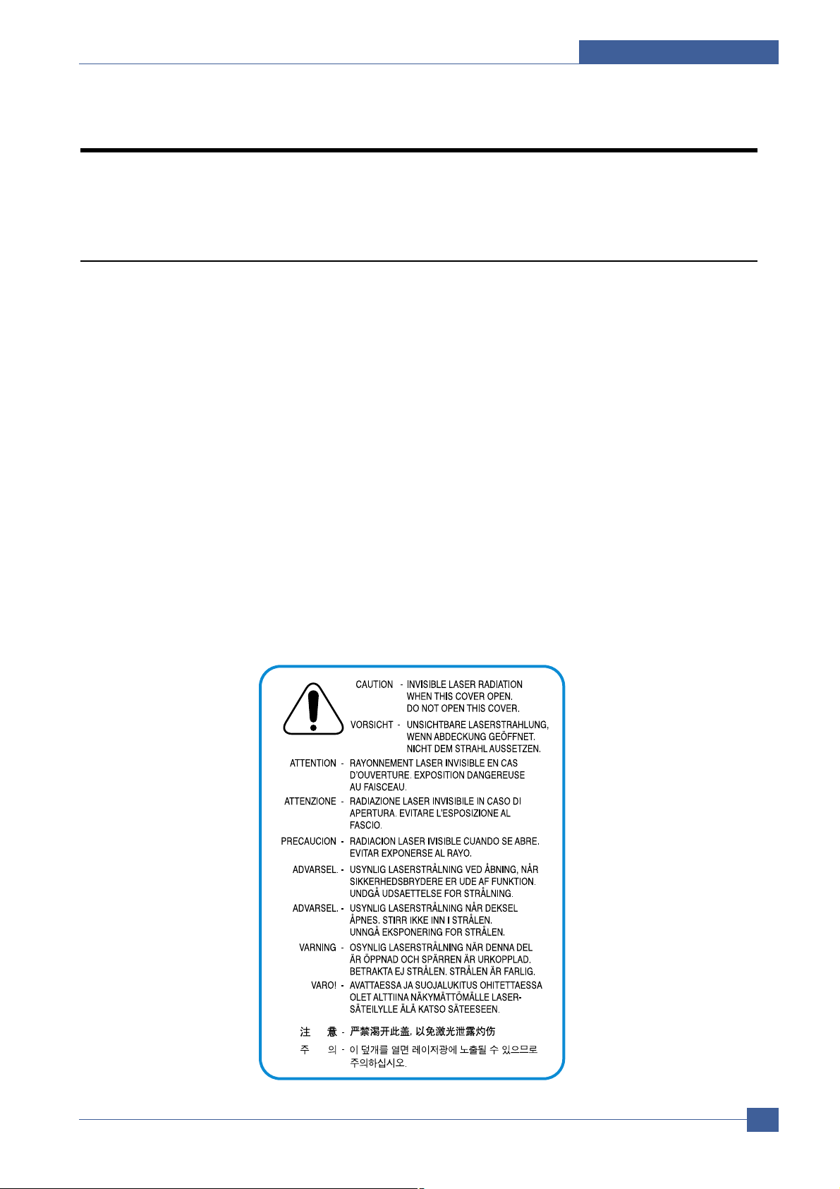
(3) Laser Safety Statement
The Printer is certified in the U.S. to conform to the requirements of DHHS 21 CFR, chapter 1 Subchapter J
for Class 1(1) laser products, and elsewhere, is certified as a Class I laser product conforming to the
requirements of IEC 825.
Class I laser products are not considered to be hazardous. The laser system and printer are designed so
there is never any human access to laser radiation above a Class I level during normal operation, user
maintenance, or prescribed service condition.
Warning >> Never operate or service the printer with the protective cover removed from Laser/Scanner assembly. The reflected
beam, although invisible, can damage your eyes. When using this product, these basic safety precautions should
always be followed to reduce risk of fire, electric shock, and injury to persons.
Page 6

Samsung Electronics
Service Manual
Precautions
1-2
1.2 Safety Caution
1.2.1 Noxious Material Precaution
The toner in a printer cartridge contains a chemical material, which may harm human body if it is swallowed.
Please keep children out of reach of the toner cartridge.
1.2.2 Electric Shock or fire Precaution
It is possible to get electric shock or burn by fire if you don't fallow the instructions of the manual.
(1) Use exact voltage. Please use an exact voltage and wall socket. If not, a fire or an electric leakage can be
caused.
(2) Use authorized power cord. Do use the power cord supplied with PRINTER. Afire can happen when over cur-
rent flows in the power cord.
(3) Do not insert many cords in an outlet. A fire can be occurred due to flow over current in an outlet.
(4) Do not put water or extraneous matter in the PRINTER. Please do not put water, other liquid, pin, clip, etc. It
can cause a fire, electric shock, or malfunction. If this occurs, turn off the power and remove the power plug
from outlet immediately.
(5) Do not touch the power plug with wet hand. When servicing, remove the power plug from outlet. Do not insert
or take off it with wet hand. Electric shock can be occurr.
(6) Caution when inserting or taking off the power plug. The power plug has to be inserted completely. If not, a fire
can be caused due to poor contact. When taking off the power plug, grip the plug and take it off. If grip the line
and pull over, it could be damaged. A fire or electric shock could happen.
(7) Management of power cord. Do not bend, twist, or bind it and place other materials on it. Do not fix with sta-
ples. If the power cord gets damaged, a fire or electric shock can happen. A damaged power cord must be
replaced immediately. Do not repair the damaged part and reuse it. A repaired part with plastic tape can be
cause a fire or electric shock. Do not spread chemicals on the power cord. Do not spread insecticide on the
power cord. A fire or electric shock can be happen due to thinner(weak) cover of the power cord.
(8) Check whether the power outlet and the power plug are damaged, pressed, chopped, or blazing fire or not.
When such inferiorities are found, repair it immediately. Do not make it pressed or chopped when moving the
machine.
(9) Caution when there is thundering or lightning, and being flash of lightening. It causes a fire or electric shock.
Take the power plug off there is thunder. Do not touch cable and device when thundering and flash of lighten-
ing.
(10) Avoid the place where is moisture or has dust. Do not install the printer where lots of dust or around humidifi-
er. Afire can occurred. A plug part need to clean well with dried fabric to remove dust. If water drops are
dripped on the place covered with dust, a fire can occurred.
(1 1) A void direct sunlight. Do not install the printer near window where direct contacts to the sunlight. If the
machine contacts sunlight long time, the machine cannot work properly because inner temperature of the
machine is getting hotter. Afire can occur.
(12) Turn off the power and take off the plug when smoke, strange smell, or sound from the machine. If you keep
using it, a fire can be occurred.
(13) Do not insert steel or metal piece inside/outside of the machine. Do not put steel or metal piece into a ventila-
tor. An electric shock could happened.
Page 7

Precautions
Samsung Electronics
Service Manual
1-3
1.2.3 Handling Precautions
If you ignore this information, you could harm machine and could be damaged.
(1) Do not install it on different levels, or slanted floor.
Please confirm whether it is balanced or not after installation. If it is unbalanced, an accident can be hap-
pened due to the machine falling over.
(2) Be careful not to insert a finger or hair in the rotating unit.
Be careful not to insert a finger of hair in the rotating unit (motor, fan, paper feeding part, etc) while the
machine is operating. Once it happens, you could be harmed.
(3) Do not place a pot containing water/chemical or small metals. If they got caught into the inner side of
machine, a fire or electric shock can be occurred.
(4) Do not install it where lots of moisture or dust exists or where raindrop reaches. A fire or electric shock
can be caused.
(5) Do not place a candlelight, burning cigarette, and etc. on the machine. Do not install it near to heater. A
fire can be occurred.
1.2.4 Assembly/Disassembly precaution
When replacing parts, do it very carefully. Memorize the location of each cable before replace parts for reconnecting it afterwards. Memorize. Please perform the steps below before replace or disassembly the parts.
(1) Check the contents stored in the memory. All the information will be erased after replacing main board.
The information needed to keep has to be written down.
(2) Before servicing or replacing electric parts, take off plug.
(3) Take off printer cables and power cord connected to printer.
(4) Use formal parts and same standardized goods when replacing parts.Must check the product name,
part cord, rated voltage, rated current, operating temperature, etc.
(5) Do not over-force when release or tighten up the plastic parts.
(6) Be careful not to drop small parts such as screws in the printer.
(7) Be careful not to change the location of small parts such as screws when assembling and disassembling.
(8) Remove dust or foreign matters completely to prevent fire of tracking, short, or etc.
(9) After finished repair, check the assembling state whether it is same as before the repair or not.
Page 8

Samsung Electronics
Service Manual
Precautions
1-4
1.3 ESD Precautions
Certain semiconductor devices can be easily damaged by static electricity . Such components are commonly called
“Electrostatically Sensitive (ES) Devices”, or ESDs. Examples of typical ESDs are: integrated circuits, some field
effect transistors, and semiconductor “chip” components.
The techniques outlined below should be followed to help reduce the incidence of component damage caused by
static electricity.
Caution >>Be sure no power is applied to the chassis or circuit, and observe all other safety precautions.
1. Immediately before handling a semiconductor component or semiconductor-equipped assembly , drain off any
electrostatic charge on your body by touching a known earth ground. Alternatively , employ a commercially available wrist strap device, which should be removed for your personal safety reasons prior to applying power to the
unit under test.
2. After removing an electrical assembly equipped with ESDs, place the assembly on a conductive surface, such
as aluminum or copper foil, or conductive foam, to prevent electrostatic charge buildup in the vicinity of the
assembly .
3. Use only a grounded tip soldering iron to solder or desolder ESDs.
4. Use only an “anti-static” solder removal device. Some solder removal devices not classified as “anti-static” can
generate electrical charges sufficient to damage ESDs.
5. Do not use Freon-propelled chemicals. When sprayed, these can generate electrical charges sufficient to dam-
age ESDs.
6. Do not remove a replacement ESD from its protective packaging until immediately before installing it. Most
replacement ESDs are packaged with all leads shorted together by conductive foam, aluminum foil, or a comparable conductive material.
7. Immediately before removing the protective shorting material from the leads of a replacement ESD, touch the
protective material to the chassis or circuit assembly into which the device will be installed.
8. Maintain continuous electrical contact between the ESD and the assembly into which it will be installed, until
completely plugged or soldered into the circuit.
9. Minimize bodily motions when handling unpackaged replacement ESDs. Normal motions, such as the brushing
together of clothing fabric and lifting one’s foot from a carpeted floor, can generate static electricity sufficient to
damage an ESD.
Page 9
Product Specifications
Samsung Electronics
Service Manual
2-1
2
2
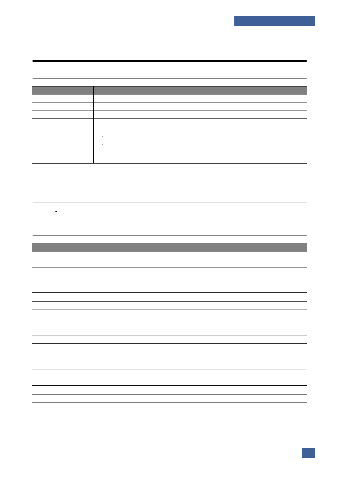
Item Descriptions Remark
Basic Model ML-2571N
Series Model ML-2510, ML-2570
Market of Sailes Persnal user Laser printer.(Low Price for small work Group.)
Specification
24ppm(Ltr. 25ppm), Jupiter 4e 150MHz, 8Mbytes SDRAM,
SPGP V3 400MHz, 32Mbytes SDRAM
1K(initial), 3K(sailes)
USB 1.1 (Compatible with USB 2.0) + IEEE 1284 Parallel : ML-2510
USB 2.0 + IEEE 1284 Parallel : ML-2570, ML-2571N
250pages feeding, 100pages Face Down
2.2 Specifications
Product Specifications are subject to change without notice. See below for product specifications.
2.2.1 General Specifications
Item Descriptions
Print Method Electro-photographic Printing
Developing system
Non-Magnetic, Mono-Component Developing System
Print Speed 24 PPM : A4 size
25 PPM (Letter size)
Resolution True 1200 X 600 DPI, 1200 X 1200(ML-2570/2571N)
Source of Light Laser diode (LSU : Laser Scanning Unit)
Warm-Up Time Cold Warm-up : 15sec, Sleep mode : 15sec
First Print Time Less than 9 seconds (Ready to 1st page out)
Feed Method Cassette & Manual
Media Size 76 X 128mm (3 x 5”) to 216 X 356mm (8.5 X 14”)
Paper thickness Cassette : 16 ~28 lb , Manual Feeder : 16 ~ 43 lb
Size(W X D X H) 352 X 298 X 243 mm
Weight Net : 5.6Kg with out toner cartridge(W/O)
Gross : 8.7Kg(41Ib)
Acoustic Noise Stand by : Less than 35 dB
Printing : Less than 53 dB
Power save mode Yes
Toner save mode Yes
Machine Life 50,000pages
2. Product Specifications
2.1 Product Overview
Page 10

Samsung Electronics
Service Manual
Product Specifications
2-2
Item Descriptions
Periodic Replacing Parts Pick Up Roller : 50,000 Pages
Same with Machine Life Transfer Roller : 50,000 Pages
Fuser Assembly : 50,000 Pages
Toner Sensor No
Toner Type Non-Magnetic Contact System
Toner Initial 1,000 sheets@ISO 19752 Standard coverage
Toner sale 3,000 sheets@ISO 19752 Standard coverage
Cassette - Paper capacity : 250sheets
- Paper weight : 60 ~ 163 g/
/ 16 ~ 43 lbs
2.2.2 Controller
Item Descriptions
Processor(CPU) Jupiter 4e 150MHz/SPGP V3 400MHz
Memory Standard/Max. : 8MB(Max. 8MB) - ML-2510/32MB(Max. 32MB) - ML-2570/2571N
Type : SDRAM
Expand Memory Slot, Type : NO
Compression Technology : MET(Memory Enhancement Technology)
(Emulation) Standard : SPL/PCL
Auto Emulation Sensing : YES
(Interface) USB 1.1 (Compatible with USB 2.0)+IEEE 1284 for ML-2510,
USB 2.0+IEEE 1284 for ML-2570/2571N
Option : NO
Auto Interface Sensing : YES
Font Type : Windows Fonts
Number : NO
Test Print Demo Mode : Press the Demo Key for 2 Seconds
Configration Mode : Press the Demo Key for 4 Seconds
Cleaning Mode : Not Support
Service Mode : Press the Demo Key when Power on(F/W Download)
ML-2510 model : I/O Support(USB 1.1 + IEEE 1284 Parallel port)
ML-2570/2571N model : I/O Support(USB 2.0 + IEEE 1284 Parallel port)
Page 11
Product Specifications
Samsung Electronics
Service Manual
2-3
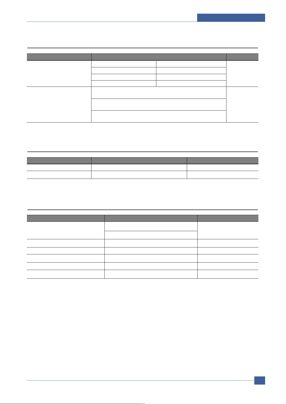
2.2.3 Electrical Specification
Item Descriptions Remark
Input Voltage Nominal input voltage 220~240 VAC
Input voltage range 198~255 VAC
Nominal frequency 50/60 MHz
Frequency tolerance +3Hz
Power Consumption Printing : 390W Ave(Max. 400W) - 2510 Model
400W Ave(Max. 420W) - 2570/2571N Model
Idling : 65W Ave or less-ML-2510 Model
70W Ave or less-ML-2570/2571N Model
Power Save : 6.5W Ave or less-ML-2510 Model
8.5W Ave or less-ML-2570/2571N Model
2.2.4 Environmental Range
Item Operating Storage
Temperature 10~30 oC(50-90 oF) -20~40 oC (-4~104 oF)
Humidity 20~80%RH 10~80%RH
2.2.5 T oner Cartridge
Item Descriptions Remark
Life span Starter: 1,000 Pages(initial) A4 Size, ISO 19752 Pattern
Running : 3,000 Pages(sailes) Standard Coverage SIMPLEX
Developing Method Non-magnetic Contact Developing
Charging Method Conductive Roller Charging
Toner Empty sensor No
Ozone 0.1PPM or less
Cartridge Style Single cartridge
Page 12
Samsung Electronics
Service Manual
Product Specifications
2-4
2.2.6 Paper Handling Specifications
Please refer to Paper Secifications on user Guide.
2.2.6.1 Input Paper Size
2.2.6.2 Input capacity
2.2.6.3 Output capacity
Paper paper size Cassette
A4 210 X 297 mm O
Letter 216 X 279(8.5 X 11") O
US Folio(Legal13") 216 X 330(8.5 X 13") O
Legal(Legal14") 216 X 356(8.5 X14") O
Executive 184 X 267((7.25 X10.5") O
Statement 140 X 216(5.5 x8.5") O
ISO B5 176 X 250 O
JIS B5 182 X257 O
A5 148 X 210 O
A6 105 X148 O(
)
No.10 Env. 105 X 241(4.15 X 9.5") O( )
Monarch Env. 98 X191(3.87 X 7.5") O( )
DL Env. 110 X 220(4.33 X 8.66") O( )
C5 Env. 162 X 229(6.38 X 9.01") O( )
C6 Env. 114 X 162(4.49 X 6.38") O( )
Transparency(OHP) A4 or Letter O( )
Label paper A4 or Letter O( )
Item Descriptions
Cassette 250 sheets
Page 13
Product Specifications
Samsung Electronics
Service Manual
2-5
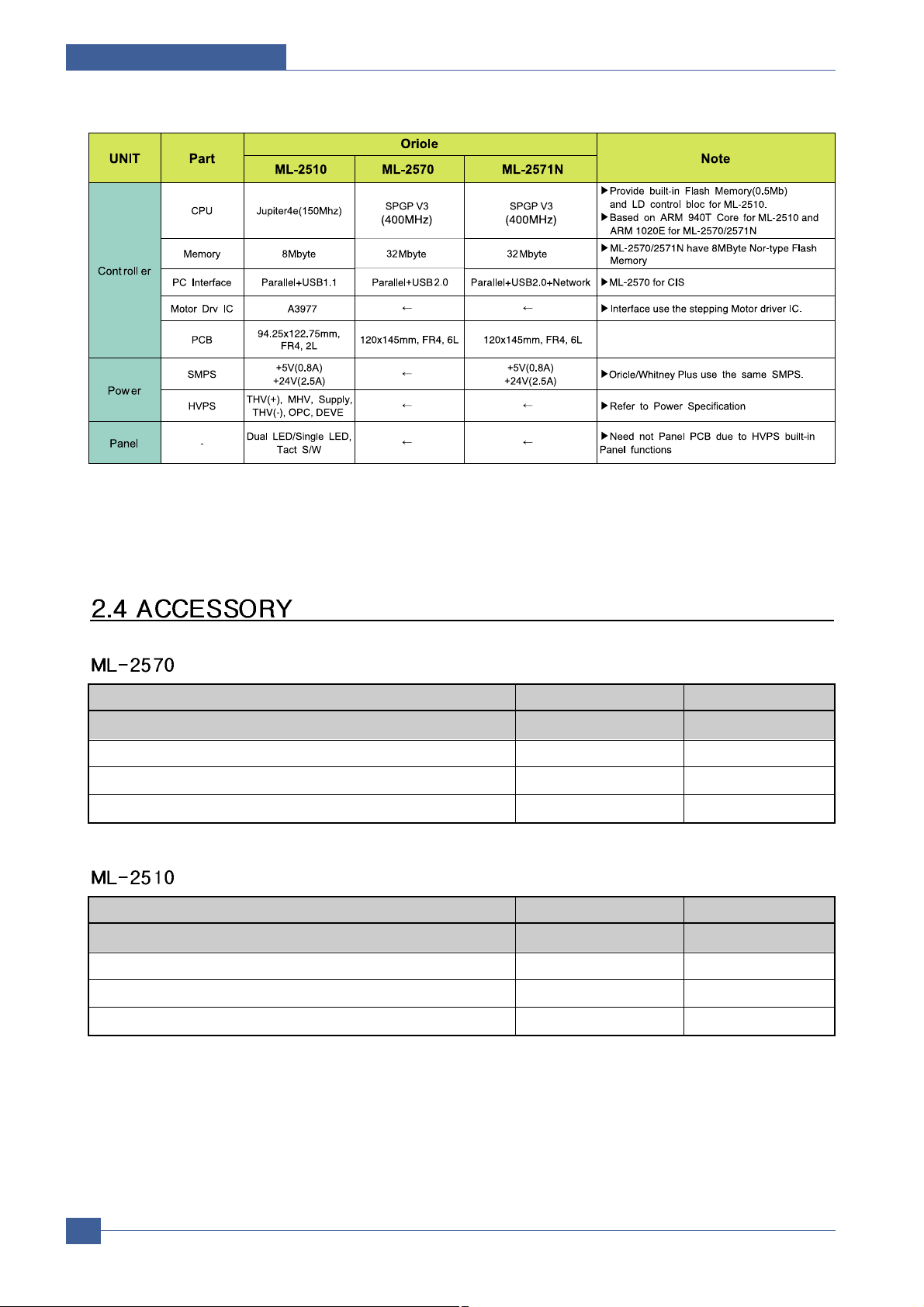
2.3 Model Comparison Table
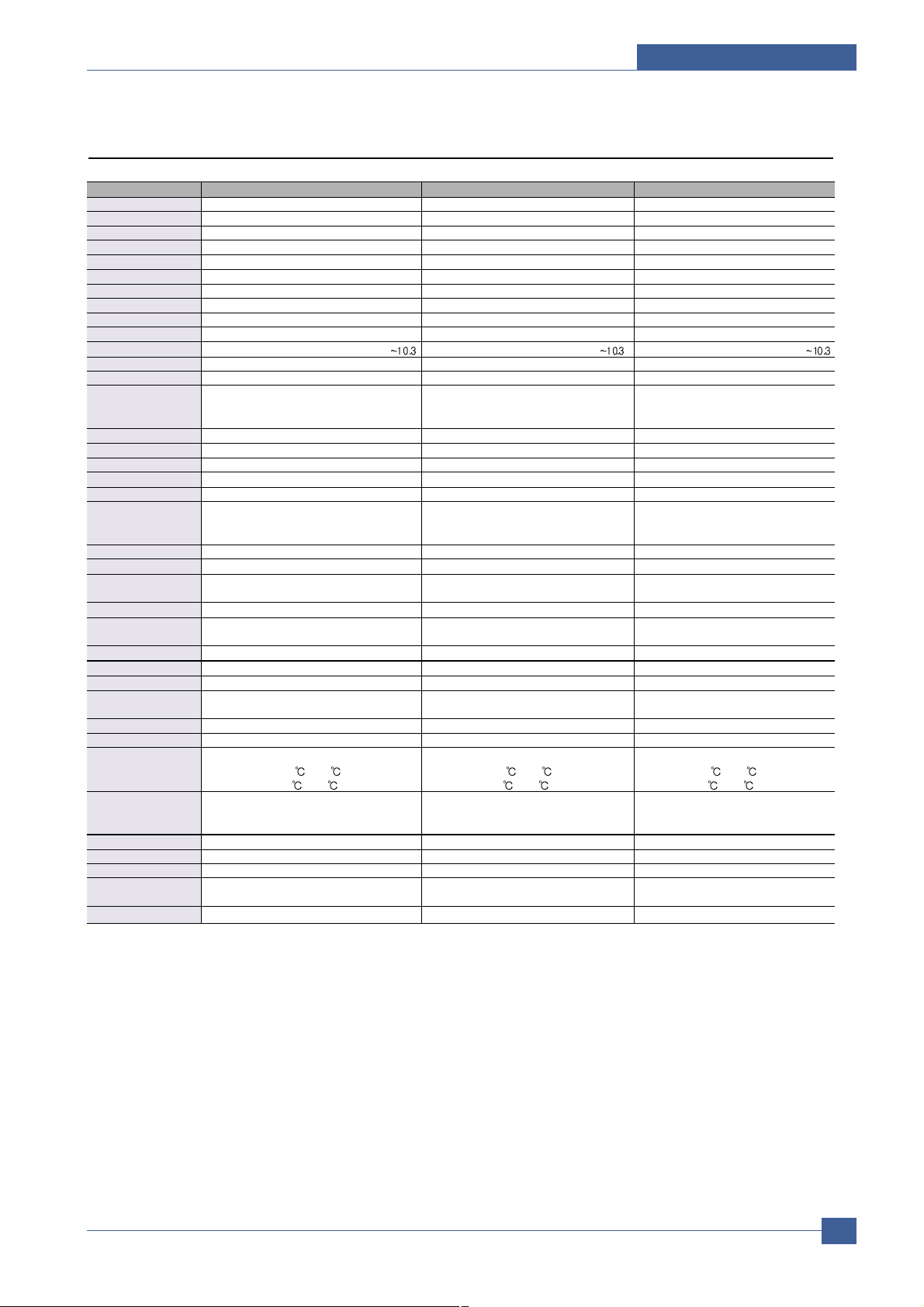
Model Name ML-2510 ML-2570 ML-2571N
Company Samsung Samsung Samsung
Printing Process
Print Method: Electrophotographic Laser Electrophotographic Laser Electrophotographic laser
Print Speed Up to 24ppm in A4, Up to 25ppm in letter Up to 24ppm in A4, Up to 25ppm in letter Up to 24ppm(A4)
FPOT 9sec 9sec 9sec
Resolusion 1200x600 1200x1200 1200x1200
Duty Cycle, Monthly up to 5000 prints per month up to 5000 prints per month up to 15,000 prints per month
Hardware Software
Processor Type Samsung Jupiter 4e 150MHz Samsung SPGP V3 400MHz Samsung SPGP V3 400MHz
Memory 8MB(8MB) 32MB SDRAM(32MB) 32MB SDRAM(32MB)
OS
Win9X/ME/2000/XP/Linux7/NT4.0/Mac OS8.6 Win9X/ME/2000/XP/Linux7/NT4.0/Mac OS8.6
Win9X/ME/2000/XP/Linux7/NT4.0/Mac OS8.6
Standard Emulations SPL PCL PCL
Interface Support
Standard Interfaces USB 1.1(Compatible with USB 2.0)+ USB 2.0 USB 2.0
IEEE 1284 Parallel IEEE 1284 Parallel IEEE 1284 Parallel
Cable Not Supply(KOR,CHINA is Supply)
Optional Interfaces N/A N/A N/A
Paper Handling
Standard Paper Input 250 Sheets Multi-purpose Tray 250 Sheets Multi-purpose Tray 250 Sheets Multi-purpose Tray
Paper Output Face down : 100 Sheet(TBD) Face down : 100 Sheet(TBD) 100 Sheet Face Down Tray
Duplexing Manual Manual Manual
Paper Weight :
- Plain paper 16 to 24 lb. Bond(60 to 90g/m2) 16 to 24 lb. Bond(60 to 90g/m2) 16 to 24 lb. Bond(60 to 90g/m2)
- Thick stock 24 - 90 lb. Index(163g/m2) 24 - 90 lb. Index(163g/m2) 24 - 90 lb. Index(163g/m2)
Physical
Type Laser Printer with Internal Controller Laser Printer with Internal Controller Laser Printer with Internal Controller
Dimensions w/output
352mm x 298mm x 243mm 352mm x 298mm x 243mm 352mm x 298mm x 243mm
tray extended(WxDxH)
Weight(without cartridge)
5.6kg 5.6kg 5.6kg
Carton Dimensions
455mm x 415mm x 325mm 455mm x 415mm x 325mm 508mm x 425mm x 265mm
(WxDxH)
Weight(as shipped) 8.7kg 8.7kg 8.7kg
Electical
Power Requirements
Power Consumption Power Consumption Power Consumption Power Consumption
390W printing, 6.5W Down Sleep Mode 400W printing, 8.5W Down Sleep Mode 400W printing, 8.5W Down Sleep Mode
Energy Star* Compliant
Yes Yes Yes
Environmental
Temprature :
- Operating 10 to 32 10 to 32 10 to 32
- Non-Operating 0 to 40 0 to 40 0 to 40
Humidity :
- Operating : 20% to 80% RH : 20% to 80% RH : 20% to 80% RH
- Non-Operating : 20% to 80% RH : 20% to 80% RH : 20% to 80% RH
Noise Level :
Operating Operating : <53dB(A), Standby : <35dB(A) Operating : <53dB(A), Standby : <35dB(A) Operating : <53dB(A), Standby : <35dB(A)
Consumables
Starter
up to 1,000 pages(A4/Letter) at ISO 5% coverage
up to 1,000 pages(A4/Letter) at ISO 5% coverage
up to 1,000 pages(A4/Letter) at ISO 5% coverage
continuous printing. continuous printing. continuous printing.
Replacement up to 3,000 pages(A4/Letter) at ISO 5% coverage up to 3,000 pages(A4/Letter) at ISO 5% coverage
up to 3,000 pages(A4/Letter) at ISO 5% coverage
Page 14
Samsung Electronics
Service Manual
Product Specifications
2-6
*. These model are as yet undeveloped.
Acessory Code Quantity
INA-ACCESSORY JC99-01993J -
S/W APPLICATION-CD JC46-00287A 1
COVER-M_PAPER (PAPER COVER) JC63-01119A 1
MANUAL-(CARD)WARRANTY CARD JC68-00690A 1
Acessory Code Quantity
INA-ACCESSORY JC99-01986C -
S/W APPLICATION-CD JC46-00291A 1
COVER-M_PAPER (PAPER COVER) JC63-01119A 1
MANUAL-(CARD)WARRANTY CARD JC68-00690A 1
Page 15
System Overview
Samsung Electronics
Service Manual
3-1
3
3
3. System Overview
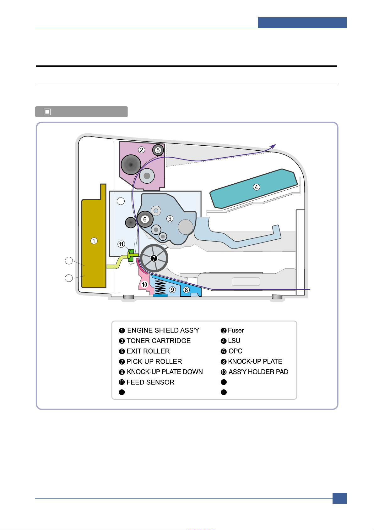
3.1 System Outline
Paper Path Layout
12
14
13
BIN PATH
MAIN PBA
SMPS HVPS
13
12
14
Page 16
Samsung Electronics
Service Manual
System Overview
3-2
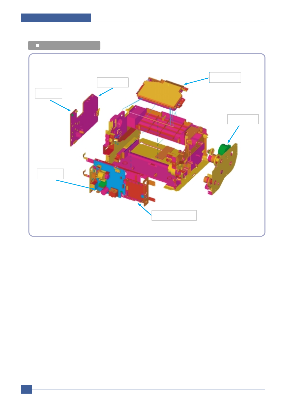
Unit Layout
HVPS
SMPS
Main PBA
Motor
LSU
Panel
Page 17

System Overview
Samsung Electronics
Service Manual
3-3
3.1.1 Feeding
There are the C-path type, which loads papers, and the manual feeder, which supplies paper one by one.The
cassette has the function pad which separates paper one by one, and it has the sensor function to check the
existence of the loading paper.
1) Feeding Type : MPF Type
2) Feeding Standard : Center Loading
3) Feeding Qty : Cassette 250 sheets (75g/ , 20lb paper standard)
4) Manual 1 sheet (Paper, OHP, Envelope etc.)
5) Separating Type : Cassette - Friction Pad Type
6) Manual : None
7) Driver Type : Driving by Gearing from Main Motor
8) Pick_up Roller Driver : Solenoid
9) Paper detecting Sensor : Photo Sensor
10) Paper Size Sensor : None
11) Paper Exit Type : Face Down
3.1.2 T ransfer Ass’y
The transfer roller delivers the toner of the OPC drum to the paper.
- The life span : Print over 50,000 sheets (in 16 ~30 )
3.1.3 Driver Ass’y
It is a power delivery unit by gearing. By driving the motor, it supplies the power to the feeding unit, the fusing unit,
and the distributing unit.(Motor drive IC : A3977)
- It is a power delivery unit by gearing : Feeder/Developer Motor Fuser/Exit
3.1.4 FUSER
The fuser is consisted of the Heat Lamp,Heat Roller,Pressure Roller,Thermister and Thermostat.
It adheres the toner on the paper with pressure and heat to complete the printing job.
- Life Cycle : 50K(pages)
Page 18

Samsung Electronics
Service Manual
System Overview
3-4
1) Heat Lamp
. Heat Lamp Terminal Shape : Terminal Single Type
. Voltage 120 V : 115 + /- 5 %
220 V : 230 + /- 5 %
. Capacity : 750 Watt + /- 30 W
. Life : 3000 Hr
2) Thermostat
. Thermostat Type : Non-Contact type THERMOSTAT
. Control Temperature : 150 5
3) Thermistor
. Thermistor Type : FS-50004 (SEMITEC 364Fs Type)
. Temperature Resistance : 7 (180 )
. SYSTEM Temperature SETTING
- Stand by : 160 + /- 5
- Printing : 180 + /- 5 (before 30pages)
75 + /- 5 (after 30pages)
- Overshoot : 200 or less
- Overheat : 210 or less
4) Heat roller
. Length : 254 mm
. Valid length : 222 mm
. GND Type : H/R Bearing Grounding type By SECC Fuser frame
5) Pressure roller
. Shaft
- Length : 239.5 mm
. Rubber
- Length : 222 mm
6) Paper separation method
Teflon Coating with mold Claw System
7) Safety Relevant Facts
. Protecting device when overheating
- 1st protecting device : H/W cuts off when detecting an overheating
- 2st protecting device : S/W cuts off when detecting overheating
- 3st protecting device : Thermostat cuts off the power
. Safety device
- The power of Fuser is cut-off after front cover is open.
- The overheating safety device for customer
- The surface temperature of the Fuser Cover is under 80
Page 19
System Overview
Samsung Electronics
Service Manual
3-5
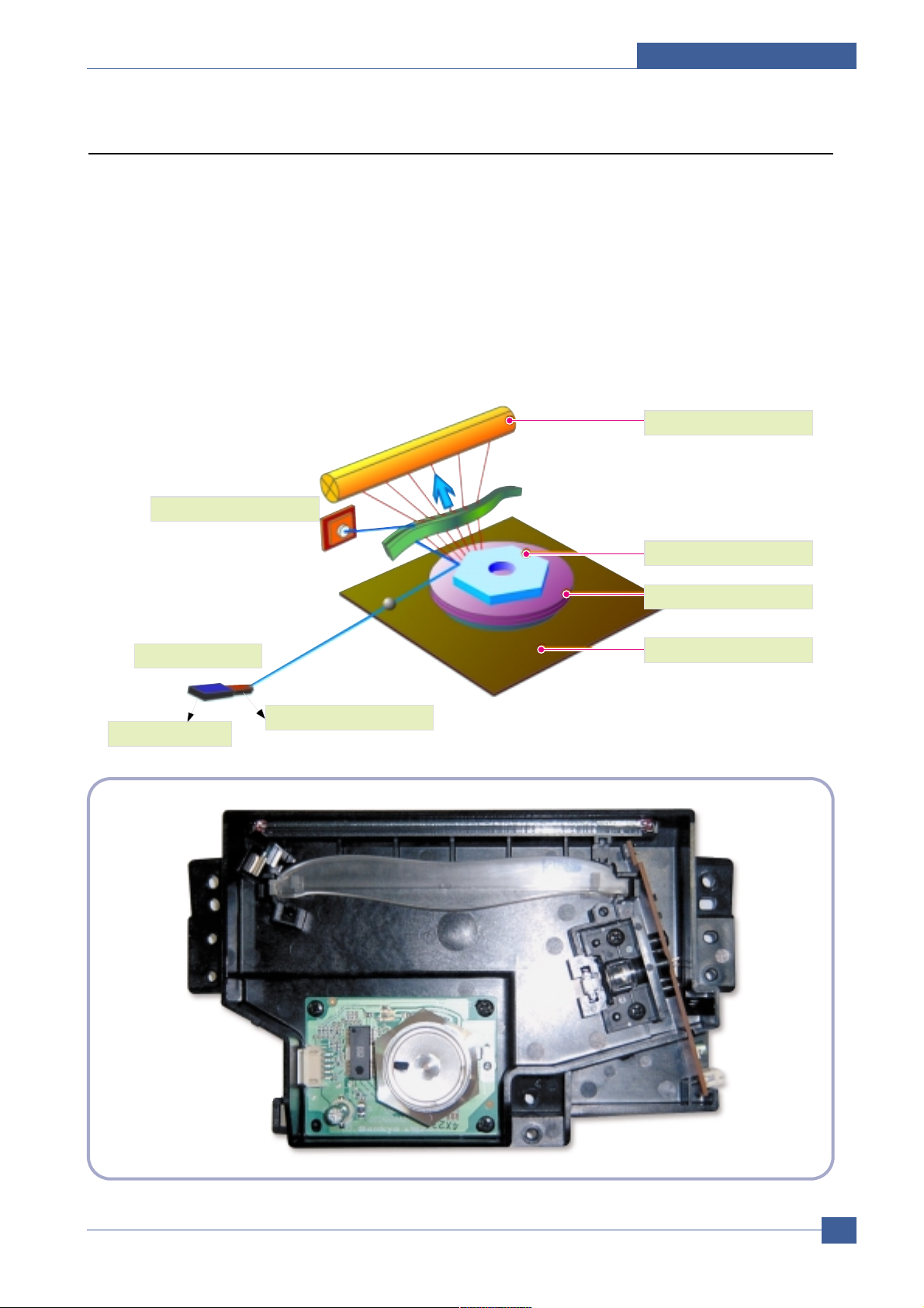
3.1.5 LSU (Laser Scanner Unit)
The LSU unit is controlled by video controller. It scans the video data received from video controller with laser beam
by using the rotation principle of the polygon mirror to create the latent image on the OPC drum. It is the core part of
LBP.
The OPC drum rotates as the same speed as the paper feeding speed. It creates the /HSYNC signal and sends it
to the engine when the laser beam of the LSU reaches the end of the polygon mirror, and the engine detects the
/HSYNC signal to arrange the vertical line of the image on the paper. After detecting the /HSYNC signal, the image
data is sent to the LSU to arrange the its margin on the paper. The one side of the polygon mirror is one line for
scanning..
OPC Drum
Photo Diode
LD Driver circit
Protector panel
LD(Laser Diode)
Polygon Mirror
Polygon Motor
Motor Driver
Page 20
Samsung Electronics
Service Manual
System Overview
3-6
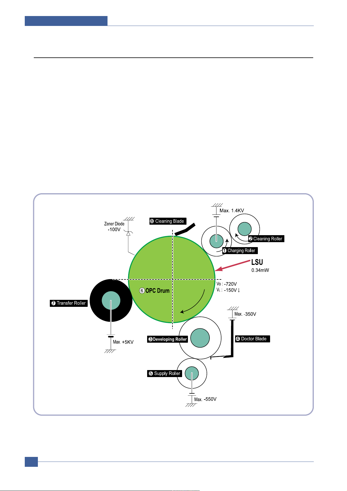
3.1.6 T oner Cartridge
By using the electronic photo process, it creates a visual image. In the toner cartridge, the OPC unit and the
developer unit are in a body. The OPC unit has OPC drum and charging roller, and the developer unit has toner,
toner cartridge, supply roller, developing roller, and blade (Doctor blade)
- Developing Method: Non magnetic 1 element contacting method
- Toner: Non magnetic 1 element shatter type toner
- The life span of toner: 3,000 sheets (ISO 19752 Pattern/A4 standard)
- Toner Cartridge : Initial(1,000), Sales(2,000)
- Toner remaining amount detecting sensor: None
- OPC Cleaning: Collect the toner by using electric static + FILM OPC
- Management of disusable toner: Collect the toner by using electric static (Clenerless Type- No disusable
toner)
- OPC Drum protecting Shutter: None
- Classifying device for toner cartridge: ID is classified by interruption of the frame channel.
Page 21

System Overview
Samsung Electronics
Service Manual
3-7
3.2 H/W Structure and Descriptions
3.2.1 H/W Overview
ML-2510/2570/2571N is roughly made up Main Control part and SMPS/HVPS part.
Main Controller uses Jupiter4E for ML-2510 and SPGP V3 for ML-2570/2571N, which is on chip micro controller
and developed for Low-end Laser Beam Printer.
Jupter4E and SPGP V3 provide provides the integrated printing functions such as Printer video controller, Laser
Scan Unit controller, PWM controller and Bi-polar Stepper Motor Controller and has USB and IEEE 1284 Parallel
Interface capacity.
3.2.1.1. Main Control
ML-2510/2570/2571N of Main Control are composed of CPU and Print and operate follows function by CPU
- Bus Control, I/o
- Handling, each Driver and PC Interface
Main Control operate its full function on the Main B'd and CPU control Controller ASIC.
3.2.1.2 CPU
ML-2510 Use 32Bit RISC Processor of Jupiter4e, which is built in Memory, while ML-2570/2571N sue
SPGP V3, They control system by operating operation block of the system.
SMPS
HVPS
Jupiter IV ASIC for 2510
SPGP V3 for 2570/2571N
V1.1 USB for 2510
V2.0 USB for 2570/2571N
Printer Engine B’D
DRAM 8M Byte for 2510
32MByte for 2570/2571N
Flash Memory for 2510
8MByte for 2570/2571N
OPE B’D
(Build-in HVPS)
Main Controller
LSU
Motor
Page 22

Samsung Electronics
Service Manual
System Overview
3-8
- Main Function Block: Completely Integrated System for Embedded Applications,
32 Bit Risc Architecture for ML-2510 and ARM10 CPU for
ML-2570/2571N ARM9 CPU
LSU Interface Module for Interfacing PVC with LSU
2 Channel General Purpose DMA Controller for High Speed I/O
Dual Memory Bus Architecture
- Operation Frequency : 150MHz for ML-2510/400MHz for ML-2570/2571N
- Operation Voltage : 3.3V
- POWER ON RESET TIME : 6.6ms below
3.2.1.3 Flash Memory
Store System Program and can be down load System Program through PC Interface
- Capacity : 8M Byte for ML-2570/2571N, ML-2510 uses 0.5M Byte ASIC built flash memory
- Access Time : 70 nsec
3.2.1.4 DRAM
When Printing, use Band Buffer, System Working Memory Area .
- 8M capa : 8M Byte basic for ML-2510
8M :Printing System Working Memory Area
- 32M capa : 32M Byte basic for ML-2570/2571N
32M :Printing System Working Memory Area
- Access Time : 60 nsec
3.2.1.5 ENGINE
This recording method is electrophography method using LSU, which toner is composed of 1 component
and non magnetic.
1) Recording Method : LSU(Laser Scanning Unit)
2) Printing Speed :24ppm
(In continuing printing base A4, printing pages from 2nd to last during 1min)
3) Recording Density : 1200 x 600dpi
4) Cassette Capa. : Cassette : 250sheets(75g Base),
Manual : N/A((DRIVE Selection : Paper, OHP, Envelop - 1 sheet)
5) Paper Size : Cassette ,Manual; Width = 76 ~ 216mm, Length = 125mm ~ 356mm
6) Effective recording size
- A4 : 202 x 291 mm
- Letter : 208 x 273 mm
- Legal : 208 x 350 mm
- Folio : 208 x 325 mm
- Top Margin : 4.23 ° 3 mm
- Left, Right Margin : 4.23 ° 3 mm
7) CRU(Toner Cartridge)Life : 3,000pages Printing(A4, 5% Pattern Printing)
8) First Print Out Time : within 9sec( Standby )
9) Warming up time : within 15sec (Ambient : 25° )
Page 23
System Overview
Samsung Electronics
Service Manual
3-9
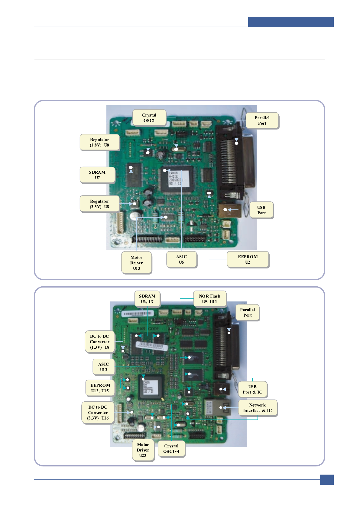
3.2.2 Main Board
Main Board are composed of Engine and Controller on the one-Board.
Main Board control to send Current Imagedml Video Data to LSU to print and have motor Driving and Circuit for the
current driving and also include Paper Exit Sensor, Cover Open s/w, panel s/w.
< ML-2510 >
< ML-2570/2571N >
Page 24

Samsung Electronics
Service Manual
System Overview
3-10
U6(Jupiter 4E for ML-2510 and SPGP V3 for ML-2570/2571N)
- ML-2510 use Jupiter4E which has a CPU core CLK with over 150MHz and a System bus 80MHz.
- It use 3.3V for operation voltage and I/O, It uses 80MHz for system bus CLK, Built in Flash Memory.
- ML-2570/2571N use SPGP V3 which has a CPU core CLK with over 400MHz and a System bus 100MHz.
SDRAM
- Main memory. SDCLK is 75Mhz for ML-2510, SDCLIC is 100Mhz for ML-2570/2571N.
A3977
- It is an Main motor driver IC and controls the motion of main motor.
Regulator
- It Supplies the core voltage to CPU by converting 3.3V to 1.8V for ML-2510
EEPROM(U8 : 93C66 for ML-2510, 24C32 for ML-2570/2571N.
- It is an EEPROM with 12C method.
SMPS connector(CN8)
- It connects SMPS, supplies the power, and delivers the high voltage contol signal, etc. If a harness is not normally
connected to this connector, power cannot be supplied.
LSU connector(CN12)
- It connects a LSU.
DC Motor connector(CN11)
- It connects an main motor and drive a DC motor.
HVPS connector(CN10)
- It connects a HVPS.
DCU connector(CN1)
- It interface a DCU-JIG
USB connector(CN6)
- It interface the computer.
Network Connector(ML-2571N only)
- It interface the network
IEEE 1284 Parallel Connector
- It interface the computer.
DC To DC Converter
- It supplies the core sltage to CPU
by Converting 3.3V to 1.3V for ML-2570/2571N
Page 25

System Overview
Samsung Electronics
Service Manual
3-11
3.2.3 Asic(Jupiter 4E) Specification
3.2.3.1 Introduction
Jupiter4E is One-Chip micro-Controller for Low cust Laser beam Printer.
1. One Chip Laser Beam Printer Controller
- GDI only
- AMBA AHB used for high speed bus transactions between masters and slaves
- AMBA APB used for low speed bus transactions between ARM core and peripherals
- 3 PLLs ( 2 Dithered PLL and 1 General PLL)
first for CPU(150MHz), AHB(75MHz), APB(75MHz),
second for USB(48MHz)
third for PVC(59MHz)
- 75MHz system operation
- 1.8V power operation
- 3.3V tolerant input and bi-directional I/Os
- SDRAM and IO Address / Data signals multiplexing
2. Integrated ARM940T 32-bit RISC embedded processor core
- 75MHz core frequency operation
- Harvard Architecture Cache : 4KByte Instruction cache, 4KByte Data cache
- Single memory bus architecture
3. Built in Flash Memory
- 4MBits (128Kx32bits)
- Serial programming mode using flash programmer tool
- Internally flash memory read / write operation support
- Programmable access timing control
4. 32MB Special function Register Area
5. Directly connected to 3 external IO banks (IOC)
- 32 MB size in each IO bank
- Programmable setup, access, hold timing
- Programmable recovery time for slow devices
- Allows to access peripheral devices such as GPIO control logic
6. Directly connected to 1 external ROM bank (ROMC)
- 32 MB size for one ROM bank
- One external flash memory attachable.
7. Directly connected to two SDRAM banks (SDRAMC)
- Extensible architecture
- Two external SDRAM attachable.
- SDRAM controller supports PC-100 and PC-133 SDRAM running at 75MHz
- Up to 32MB per bank.
- Support for SDRAM configurations including programmable column address
- Programmable refresh interval
8. Interrupt Controller (INTC)
- FIQ or IRQ mode operation selectable
- Programmable Interrupt Enable/Disable
Page 26

Samsung Electronics
Service Manual
System Overview
3-12
9. USB interface
- Version 1.1
- Four 128x8 FIFOs for Data transmission.
- Interrupt based input / output interface, no DMA based interface support
- USB wrapper for AHB interface
- AHB Bus interface
10. Serial port interface (UART)
- Programmable Baud Rate
- 2 channel Independent Full Duplex UART
- Polling, Interrupt based operation support
- Max 16 byte FIFO to handle SIR Bit Rate Speed
11. Printer video controller for LBP engines (PVC)
- 20MHz video rate (Hummingbird 2 : letter - 21 ppm, A4 : 20ppm)
- video data transmitted through LSU Controller
12. Laser Scan Unit (LSU) Controller
- Laser Scan Unit (LSU) Interface for Laser Diode turn on/off timing control
- Sample & hold period generation.
- Auto Power Control for Laser Diode with PID control method using internal 10 bits DAC.
- LSU clock generation
- Brushless DC motor control clock generation
13. ADC Interface
- 4 channels ADC interface for analog devices such as temperature sensor.
- Programmable ADC Clock Cycle.
- Automatic or Manual AD Conversion support.
- 4 Special Function Registers for monitoring the ADC results for 4 channels.
14. PWM Controller
- 4 PWM output ports - THV, BIAS, FAN control and AC ELECTRIFICATION
15. Bi-polar Stepper Motor controller (MOTORC)
- Phase generation for the purpose of paper feeding
- fixed hardware phase and current table
- programmable phase and interval time
- Interrupt based phase change operation
16. Timer
- 3 Independent Programmable Timers
- Watch Dog Timer for S/W Trap
17. Miscellaneous
- Mux controlled 24 GPI, 28 GPO & 5 GPIO ports .
- Mutual exclusive GPO/GPIO ports control by the port control enable register
- Programmable Bus Master Priority.
- Project code added.
Page 27
System Overview
Samsung Electronics
Service Manual
3-13
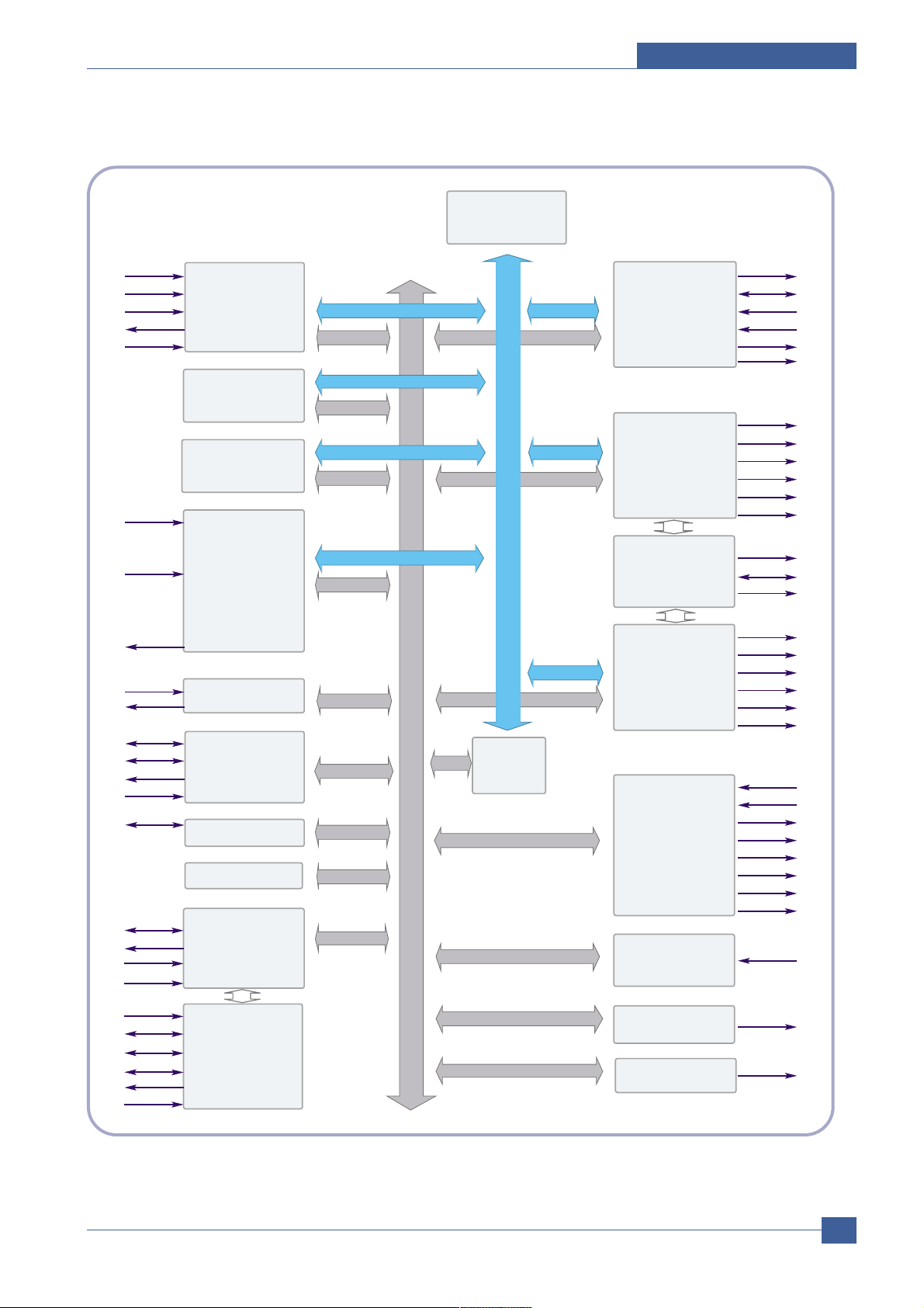
3.2.3.2 Jupiter4E Internal Block Diagram
TMS
TCK
TDI
TDO
nTRST
ARM CORE
(
ARM 940T
I/C 4KB
D/C 4 KB
)
PPI
PDE,
BUSY,
nACK,
SELECT,
PERROR,
nFAULT
PPD[7:0]
APB
BRI DGE
AHBC
( ARB,DEC,MUX)
FLASH CO RE
( mf l130_ 128Kx32 )
SCL
SDA
PROGRAM
SDRAMC
( EXT : 2 CH)
nSRAS
nSCAS
nSCS
DQM1-0
BA1-0
SCKE
ADDR18-0
DATA15-0
nOE
ADDR /DATA
BUS MUX
IOC (3CH)
/ROMC(1CH)
nIOCS1-0
INTC
TCU
MISC
PLL
( pll 2096x, pll 2073x )
CLOCK & RESET
EXTCLK
nRESET
OM2-0
CAP2-0
MOTORC
MOTPAT5-0
LSUC
( dac1264x_ 1455)
nLREADY
nHSYNC
VDO
ADC INTERFACE
( adc1275x_ pc)
ADCIN3-0
PWM
PWM3-0
LSUCLK
SCLK
A
H
B
A
P
B
A
H
B
UART
RXD1-0
TXD1-0
SHPERIOD
nLDON
DACOUT
TEST
XI
XO
USB CORE
(
USB 1 . 1
)
D+
D-
Dpullup
VBUS
nSTROBE,
nINIT,
nSLCTIN,
nAUTOFD
nROMCS
nSWE/nWE
TIC
ENEXHV
EXHV
DC2-0
PVC
nIOCS2_WE
nIOCS2_OE
nIOCS_ALL
BLDC_CLK
GPO27-0
GPIO4-0
Page 28

Samsung Electronics
Service Manual
System Overview
3-14
3.2.3.3 Asic(SPGPv3)
CPU Core : ARM1020E
- 32KB instruction cache and 32KB data cache
Operating Frequency
- CPU Core : over 300MHz
- System Bus : 100MHz
SDRAMC
- 32Bits Only, 100MHz
- 5 Banks (Up to 128MB per Bank)
ROMC
- 4 Banks (Up to 16MB per Bank)
IOC
- 6 Banks (Up to 16MB per Bank
DMAC
- 4 Channels
HPVC
- Dual/Single Beam
- LVDS Pad(VDO, HSYNC)
UART
- 5 Channels (1 Channels Supports DMA Operation)
PCI Controller
- 32Bits, 33/66MHz
- PCI Local Bus Specification rev2.2 Complaint
- Host / Agent Mode (Support 4 Devices in Host Mode)
NAND Flash Controller
- 8/16Bits, H/W EEC Generation
- Auto Boot Mode (Using Internal SRAM, 4KB)
MAC
- 10M/100Mbps
- Full IEEE 802.3 Compatibility
Engine Controller
- LSU Interface Unit
- Step Motor : 2 Channels
- PWM : 8 Channels
- ADC : 6 Channels
I2C Controller
- I2C(S-BUS) Slave Device Support(I2C Version 2.1)
RTC
- RTC Core Voltage : 3V
PLL
- 3 PLL : MAIN, PCI, PVC
3.2.3.4 Memory
Flash Memory : It stores System Program and downloads the System Program through PC Interface, and in case of
model for export it compresses the PCL font, then stores it.
- Capacity : 8M Byte (Nor Flash)
- Random Access Time : 10 us (Max)
- Serial Page Access Time : 50ns (Min)
DRAM : It is used as Swath Buffer, System Working Memory Area, etc. when printing.
It stores Font List, compressed into Flash memory, on DRAM and uses it as PCL font in case of model for export.
- Capacity : 32M Byte(STD/MAX)
- Type : SDRAM 100MHz/133MHz, 16bit
Page 29
System Overview
Samsung Electronics
Service Manual
3-15
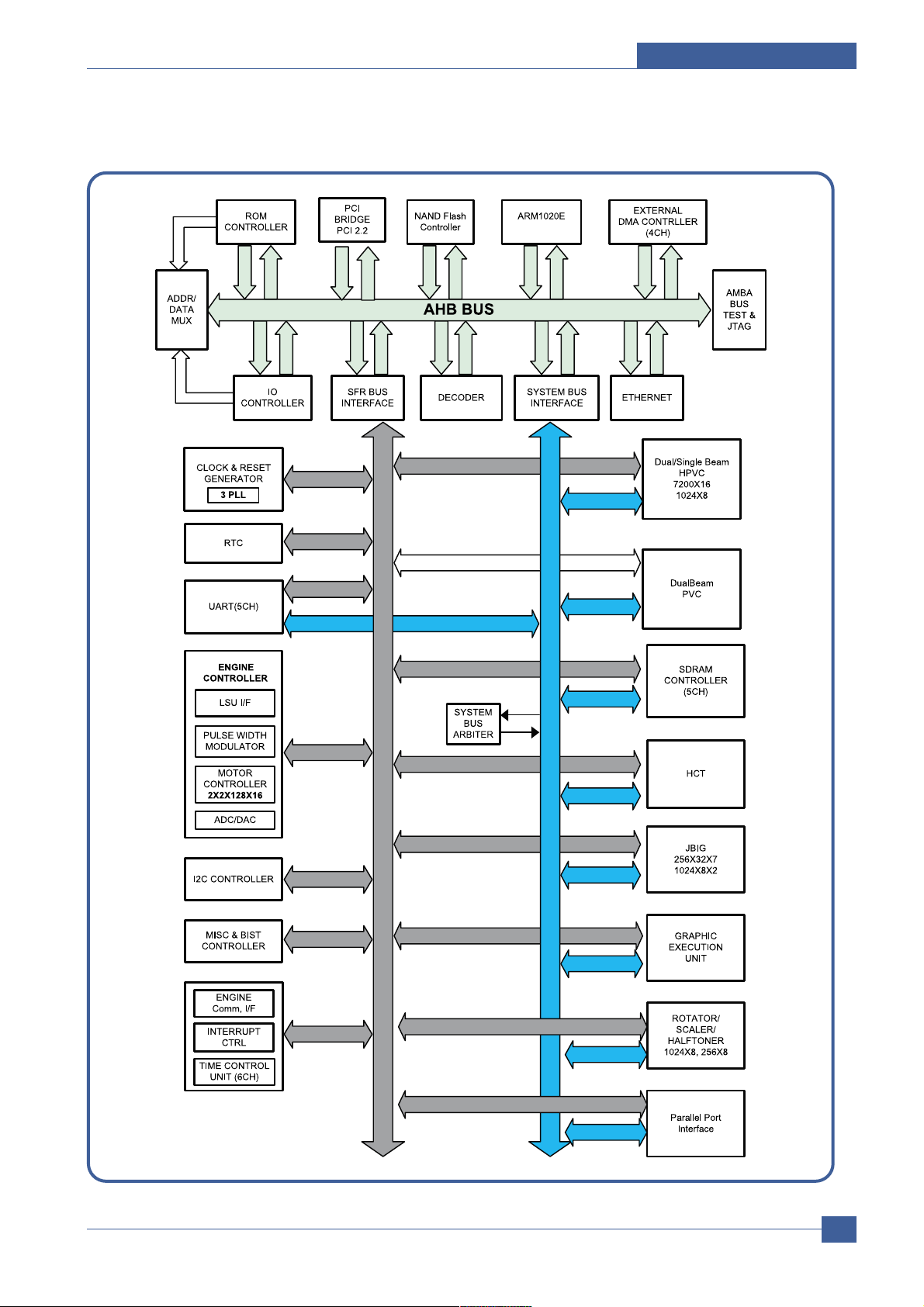
3.2.3.5 SPGPv3 Internal Block Diagram
Page 30

Samsung Electronics
Service Manual
System Overview
3-16
3.2.3.6 Flash Memory
It stores the system program and downloads system program through the PC Interface.
Capacity : 8M Byte (NOR Flash)
Random Access Time : 10 us (Max)
Serial Page Access Time : 50ns (Min)
3.2.3.7 SDRAM
It is used as swath buffer, system working memory area, etc. while Printing.
Capacity : The 32M Byte is for this model (32M :Printing System Working Memory Area )
Page 31

System Overview
Samsung Electronics
Service Manual
3-17
3.2.4 Sensor Controller
3.2.4.1 Paper Feeding/Width
When a paper passes an actuator of a feed sensor unit after feeding a paper into a set,it detects a signal of
the photo interrupter and informs the paper feeding status to CPU. After sensing the signal and certain time
later, it strews an image data.(Related in Paper Front Edge Adjustment)
If it could not detect the feed sensor within 1 second after feeding a paper, a paper jam0 (CPU#_) occurs.
ML-1610 differs from other general printers because it doesn’t have a paper empty sensor. It recognizes
the paper existing status by using a firmware. If a paper is not fed, it recognizes the state as no paper (Red
and Yellow lights turn on among other LEDs). With the same principle, it senses the OPC unit. After OPC
unit is mounted,the actuator operates. When it passes the actuator of sensor unit, it detects the signal of
the photo interrupter, informs the existing OPC unit to CPU, and then stays at the status.
3.2.4.2 Paper Empty Sensing
The paper empty is detected by the empty sensor mounted to an engine board and the actuator mounted
to a frame. Paper senses the on/off time of the empty sensor by using CPU and informs the normal
operation status and the jam occurrence status to CPU.
3.2.4.3 Jam Cover/Cover Open Sensing
ML-1610 uses two M/S:one senses the cover open and the other senses the jam cover open.
The cover open sensor is located on the left bottom of HVPS.When the front cover is open, +24V supplied
to each unit (DC fan,Solenoid,Main Motor,Polygon Motor Unit of LSU in Fusing Unit,and HVPS)is
interrupted.
The jam cover open sensor is located on the left bottom of SMPS. When the jam cover is open, +24V
supplied to each unit (DC fan, Solenoid, Main Motor, Polygon Motor Unit of LSU in Fusing Unit, and HVPS)
is interrupted.
D0 bit of CPU detects the jam cover open/cover open, and D7 bit of CPU detects the existence of OPC.
In this case, it informs the status to user by turning on the red LED among OP panel LEDs.
3.2.4.4 Solenoid Driving Circuit
The solenoid consists of two used for paper pick-up and MP signal. D4 bit of CPU turns it on/off, and its
driving time is 300ms. The diode protects the drive TR from the pulse (noise)generated by de-energizing
operation of solenoid.
Page 32

Samsung Electronics
Service Manual
System Overview
3-18
3.2.5 SMPS board (Switching Module Power Supply)
The SMPS supplies DC Power to the System.
It takes 110V/220V and outputs the +5V, +24V to supply the power to the main board and other board. It is
consisted of the AMPS part, which supplies the DC power for driving the system, and the AC heater control part,
which supplies the power to fuser. SMPS has two output channels. Which are 5V and +24V
Pin Signal
Pin No Pin Name
1 +24VS2
2 +24V
3 +24VS1
4 +24VS1
5 +5V
6 DGND
7 DGND
8 P_REGI
9 FUSER ON
<CON2>
Page 33

System Overview
Samsung Electronics
Service Manual
3-19
1) SMPS Specification
- AC Input
Input Rated Voltage : AC 220V ~ 240V AC 120V / AC 220V(EXP version)
Input Voltage fluctuating range : AC 90V ~ 135V / AC 180V ~ 270V(EXP version)
Rated Frequency : 50/60 Hz
Frequency Fluctuating range : 47 ~ 63 Hz
Input Current : Under 4.0Arms / 2.5Arms
(But, the status when lamp is off or rated voltage is inputted/outputted )
- Rated Output Power
- Consumption Power
- Power Cord Length : 1830° 50mm
- Power Cord Switch : Use
- Feature
. Insulating Resistance : 100 or more (at DC 500V)
. Insulating revisiting pressure : Must be no problem within 1 min. (at 1000Vac,10mA)
. Leaking Current : under 3.5mA
. Running Current : under 40A PEAK (AT 25 , COLD START)
under 50A PEAK (In other conditions)
. Rising Time : within 2Sec
. Falling Time : over 20ms
. Surge : Ring Wave 6KV-500A (Normal, Common)
No Items CH1 CH2 Remarks
1 Channel +5V +24.0V
2 Connector pin CON 3 CON 3
5V PIN : 11, 12 24V PIN : 2, 3, 4
GND PIN : 8, 9 GND PIN : 6, 7
3 Rated Output +5V 5% +24V 5%
(4.75 ~ 5.25V) (20.4 ~ 27.6V)
4 Max. Output current 0.8A 2.5A
5 Peak Loading current 1.0A 2.7A 1ms
6 RIPPLE NOISE Voltage 100mVp-p or less 500mVp-p or less
7 Maximum output 4W 60W
8 Peak output 5W 65W 1ms
9 Protecttion for loading
shorage and overflowing
current
No Items CH1(+5V) CH2(+24V) System
1 Stand-by 1.0 A 0.4 A AVG : 55 Wh
2 PRINTING 1.0 A 2.5 A AVG : 350 Wh
3 Sleep-Mode 0.8 A 0.4 A AVG : 10 Wh
Page 34

Samsung Electronics
Service Manual
System Overview
3-20
- Environment Condition
. Operating temperature range : 0 40
. Maintaining temperature range : -20 40
. Preserving Humidity Condition : 10% ~ 90% RH
. Operating atmospheric pressure range : 1atm
- EMI Requirement : CISPR ,FCC, CE, MIC,
- Safty Requrement : IEC950 UL1950, CSA950, C-UL,Semko, EK,CB,
CCC(CCIB),GOST, EPA, Power Save
3.2.6 HVPS board (High V oltage Power Supply)
The HVPS board creates the high voltage of THV/MHV/Supply/Dev and supplies it to the developer part for making
best condition to display the image. The HVPS part takes the 24V and outputs the high voltage for THV/MHV/BIAS,
and the outputted high voltage is supplied to the toner, OPC cartridge, and transfer roller.
1) Transfer High Voltage (THV+)
- Input Voltage : 24 V DC ° 15%
- Out Voltage : Max. +1.3KV ° 15% (Cleaning,200 )
- Out Voltage Trigger : 6.5
- Input Voltage Variation : 5 % below(Variation 21.6V°≠26.4V)
Load Variation : % below
- Out Voltage Rising Time : 100 ms Max
- Out Voltage Falling Time : 100 ms Max
- Transfer Variation Voltage on Environment Variation : +650 V(Duty 10%) ~ 5KV (Duty 90%)
- Control Method on environment : THV-PWM ACTIVE,transfer Active signal, of environment sensing
voltage is input and get feed back current, and recalculate it to resistence .
- Control method on transfer output voltage : It is controlled by changing its duty of THVPWM Signal as
follows. 10% Duty : +650V, 90% Duty : +5KV 5%
2) Charge Voltage (MHV)
- Input Voltage : 24 V DC 15%
- Out Voltage : -1.3KV ~ 3.2%
- Out Voltage Rising Time : 50 ms Max
- Out Voltage Falling Time : 50 ms Max
- Out Voltage Range : 30 ~ 1000
- Output Control Signal(MHV-PWM) : CPU is HV output when PWM is Low
3) Developing Voltage (DEV)
- IInput Voltage : 24 V DC 15%
- Output Voltage: -350V 4.6%
- Output Voltage Fluctuation range: PWM Control
- Input contrast of the output stability degree : 5 % or less
- Loading contrast : 5 % or less
- Output Voltage Rising Time : 50 ms Max
Page 35

System Overview
Samsung Electronics
Service Manual
3-21
- Output Voltage Falling Time : 50 ms Max
- Output Loading range : 10Mߟ ~ 1000
- Output Control Signal (BIAS-PWM) : the CPU output is HV output when PWM is low.
4) Supply
- Output Voltage : -550 V 8.6%(ZENER using, DEV )
- Input contrast of the output stability degree : under 5 %
- Loading contrast : 5 % or less
- Output Voltage Rising Time : 50 ms Max
- Output Voltage Falling Time : 50 ms Max
- Output Loading range : 10 ~ 1000
- Output Control Signal (BIAS-PWM) : the CPU is HV output when PWM is low.
Input
Page 36

Samsung Electronics
Service Manual
System Overview
3-22
3.2.7 FUSER AC POWER CONTROL
Fuser(HEAT LAMP) gets heat from AC power. The AV power controls the switch with the Triac, a semiconductor
switch. The 'ON/OFF control' is operated when the gate of the Triac is turned on/off by Phototriac (insulting part).
In other words, the AC control part is passive circuit, so it turns the heater on/off with taking signal from engine
control part.
When the 'HEATER ON' signal is turned on at engine, the LED of PC1 (Photo Triac) takes the voltage and flashes.
From the flashing light, the Triac part (light receiving part) takes the voltage, and the voltage is supplied to the gate
of Triac and flows into the Triac. As a result, the AC current flows in the heat lamp, and heat is occurred.
On the other hand, when the signal is off, the PC1 is off, the voltage is cut off at the gate of Triac, the Triac
becomes off, and then the heat lamp is turned off.
1) Triac (THY1) feature :16A, 600V SWITCHING
2) Phototriac Coupler (PC3)
. Turn On If Current : 16mA
. High Repetive Peak Off State Voltage : Min 600V
Page 37

System Overview
Samsung Electronics
Service Manual
3-23
3.3 S/W Structure and Descriptions
The purpose of this document is to describe the design specification of the Engine Control F/W for the
ML-1610.
3.3.1 Introduction
This Engine Control Firmware is a program that controls LBP Engine of the ML-1610.
This firmware is executed every 10msec as an interrupt routine of the main system. At stand-by state, this firmware
monitors the enable print command from the main system. If the enable print command is detected, this firmware
controls the Engine Mechanism according to the printing process and paper feeding state. And with the Sleep
command or Wake-Up command, this firmware controls the Engine state.
3.3.2 Engine Control F/W Overview
Engine Control F/W is executed every 10msec by timer interrupt of main system. And it consists of 3 control
modules.
- Engine Main Control, Interface Control and Sensing & Unit Control Module.
Major operations of the Engine Control F/W are following.
- Control the Pick-Up, Feeding and Discharging of Paper
- Control the LSU
- Control the HVPS for the Developer Process
- Control the Temperature of Fixing unit
Controlling selection to here is added.
- Second Cassette Feeder(SCF) : N/A
Page 38

Samsung Electronics
Service Manual
System Overview
3-24
- Architecture of Engine Control F/W
Main F/W of the printer controller
Device Units
Fixing Unit
LSU
HVPS
Fan Unit
Motors
Solenold &
Clutch
Power On
Initial
Interface Control Module
Engine Main Control Module
Sensing & Unit Control Module
Hardware Devices
& Mechanical Device
Engine F/W
Page 39

System Overview
Samsung Electronics
Service Manual
3-25
3.3.3 F/W Architecture of Engine Control Firmware
- The Engine Control Module is executed every 10msec as interrupt job of main system. There are three
control modules, i.e., Engine Main Control Module, Engine Interface Module and Sensing & Unit Control
Module.
- Probably from usual state it will be able to rehabilitated a prior to entry error state in error condition it is to
confirm. When the if rehabilitation is possible then after rehabilitating it goes back in usual state, else with
an error condition it goes in error state. Currently the rehabilitation function of the low heat error , the over
heat error and the LSU error is embodied.
- Low Heat Error
When the error occurrs, it does not indicate an error. It stores the present temperature and supplies the
heat to the fixing unit during the scheduled time. If the temperature goes up after scheduled time, it goes
back to a normal state. However, if not, it is formed that an error occurrs.
- Over Heat Error
When the error occurs, it informs an error first. It stores the present temperature as well and waits a
scheduled time. If the temperature goes down after scheduled time, then it goes back to a normal state.
However, if not, it is formed that an error occurrs.
- Lsu Error
When the error occurrs, it does not indicate an error. It accomplishes printing only again. If even time
when it judges an error, it informs an error. Concretely speaking, if the LReady or Hsync error happens,
the paper exits out beforehand. And then the engine mode is changed to recovery mode and the engine
informs the main system of the engine mode. And the engine checks the LSU error in itself. If the error
doesn’t happen, the printing job will be proceeding.
3.3.4 Engine Interface Module Design
Engine Interface Module communicates with the main system in order to receive the command from main system
and to transmit the present engine status for the requested status. There are two sub functions. One is a function to
receive the command from the main system. The other is a function that informs the main system of the current
engine status for the requested item.
3.3.5 Engine Sensing & Unit Control Module Design
Engine Sensing & Unit Control Module consists of 4 sub-functions. The first function is an ADC function that reads
the ADC values of the temperature of the fixing unit. The second one is a fixing unit control function. This function
regulates the temperature of the fixing unit within a fixed range to be set by the paper type and the number of pages
to print out. The third one is a fan control function that controls the fan unit. And the last one sets the flag that
describes the present status of each sensor.
Page 40

Samsung Electronics
Service Manual
System Overview
3-26
START
Global Timer Increment
Get A DC Value
(Tempe rature, .. )
Control the fixing unit
&
Check error condition for the fixing unit
Control the fan unit
Get status value of each sensor
&
Set present status f lag of each sensor
- F/W Architecture
Page 41

System Overview
Samsung Electronics
Service Manual
3-27
3.4 Initial Product Installation
3.4.1 Accessory List
Remove the printer and all accessories from the packing carton. Make sure that the printer has been packed with
the following items:
3.4.2 Installing the T oner Cartridge
1. Grasp the front cover and pull it toward you to open.
Page 42

Samsung Electronics
Service Manual
System Overview
3-28
2. Remove the toner cartridge from its bag and remove the paper covering the cartridge.
3. Gently shake the cartridge from side to side to distribute the toner evenly inside the cartridge.
4. Locate the cartridge slots inside the printer, one on each side.
Page 43

System Overview
Samsung Electronics
Service Manual
3-29
5. Unfold the toner cartridge handle and grasp it. Insert the cartridge in the printer until it snaps into place.
6. Close the front cover. Make sure that the cover is securely closed. If the cover is not firmly closed,
printing errors may occur when you print.
Page 44

Samsung Electronics
Service Manual
System Overview
3-30
3.4.3 Loading Paper
You can load approximately 150 sheets of paper in the tray.
1. Grasp the paper input tray and pull it toward you to open.
Pinch the rear guide and pull it out to extend the tray.
2. Prepare a stack of paper for loading by flexing or fanning them back and forth. Straighten the edges on a
level surface.
3. Load paper with the print side facing up. Make sure that all four corners are flat in the tray.
Page 45

System Overview
Samsung Electronics
Service Manual
3-31
4. Pay attention not to overload paper. Paper overloading may cause paper jams.
5. If necessary, pinch the rear guide to adjust for the paper length and pinch the side guide and slide it to
the left flush against the paper.
3.4.4 Connecting a Printer Cable
To print from your computer, you need to connect your printer to your computer with a Universal Serial Bus (USB)
cable.
1. Make sure that both the printer and the computer are turned off.
2. Plug the USB printer cable into the connector on the back of the printer.
3. Connect the other end of the cable to the USB port on your computer.
See your computer User’s Guide if you need help.
Page 46

Samsung Electronics
Service Manual
System Overview
3-32
3.4.5 T urning the Printer on
1. To print from your computer, you need to connect your printer to your computer with a Universal Serial
Bus (USB) cable.
2. Plug the other end into a properly grounded AC outlet and turn on the printer using the power switch.
3.4.6 Printing a Demo Page
Print a demo page to make sure that the printer is operating correctly.
1. Press and hold down the Cancel button on the control panel for about 2 seconds to print a demo page.
2. The Demo page shows the printer’s current configuration.
Page 47

System Overview
Samsung Electronics
Service Manual
3-33
3.4.7 Installing Printer Software
The supplied CD-ROM contains Windows printing software, Linux printing software, on-line User’s Guide and
Acrobat Reader to view the User’s Guide.
1. If you are printing from Windows
- You can install the following printer software using the CD-ROM.
• Printer driver for Windows. Use this driver to take full
- advantage of your printer’s features. For details, see Software User Guide.
• Status Monitor allows you to see the printing status of the printer. For details, see Software User
Guide.
2. If you are printing in Linux
- Go to Software User Guide for information about installing the Linux driver.
3. System Requirements
Your machine supports following operating system.
• Windows 98/Me/2000/XP - The following table shows Windows requirements.
Item Requirements
Operating System Window 98/Me/2000/XP
CPU Window 98/Me/2000/XP Pentium II 400 or higher
Window XP Pentium II 933 Ghz or higher
RAM Window 98/Me/2000 64 MB or higher
Window XP 128 MB or higher
Free Disk Space Window 98/Me/2000 300 MB or higher
Window XP 1 GB or higher
Internet Explorer 5.0 of higher
Page 48

Alignment and Adjustments
Samsung Electronics
Service Manual
4-1
4
4
4. Alignment and Adjustments
4.1 Sample Pattern
This product has the several sample patterns for maintenance. With the sample patterns, check the
existence of the abnormality. The patterns help to regularly maintain the product.
4.1.1 Printing a Demo Page
Print a demo page or a configuration sheet to make sure that the printer is operating correctly.
1) Hold down the Cancel button for about 2 seconds to print a demo page.
Page 49

Samsung Electronics
Service Manual
Alignment and Adjustments
4-2
2) The Demo page or the configuration sheet shows the printer’s current configuration.
Page 50

Alignment and Adjustments
Samsung Electronics
Service Manual
4-3
4.2 Control Panel
4.2.1 OP Panel
4.2.2 Cancel button
Printing demo page In Ready mode, press and hold this button for about 2 seconds until
all LEDs blink slowly, and release.
Manual feeding Press this button each time you load a sheet of paper in the
tray, when you select Manual Feed for Source from your software application.
Canceling print job Press this button during printing. The On Line/Error LED blinks while the
print job is cleared from both the printer and the computer, and then return to
Ready mode. This may take some time depending on the size of the print job.
In Manual Feed mode, you can’t cancel the print job by pressing this button.
LED Description
Page 51

Samsung Electronics
Service Manual
Alignment and Adjustments
4-4
COMPONENT REPLACEMENT CYCLE
Pick-up Roller 50,000 Pages
Transfer Roller 50,000 Pages
Fuser 50,000 Pages
Toner Cartridge 3,000 Pages(Sales), 1,000 Pages(Initial)
4.3 Consumables and Replacement Parts
The cycle period outlined below is a general guideline for maintenance.
The example list is for an average usage of 50 transmitted and received documents per day.
Environmental conditions and actual use will vary these factors.
The cycle period given below is for reference only.
Page 52

Alignment and Adjustments
Samsung Electronics
Service Manual
4-5
8
BIN PATH
1
2
3
4
OPC Drum
Charge Roller
Supply Roller
Developing Roller
5
6
7
Transfer Roller
Heat Roller
Pressure Roller
8
Feed Roller
4.4 Periodic Defective Image
If the delinquent image regularly occurs in the printed-paper, it is due to delinquent or damaged roller.
Refer to the table in below and check the condition of the roller.
No Roller Defective image Typical defect
1 OPC Drum 75.5mm white spot on black image or black spot
2 Charge Roller 37.7mm black spot
3 Supply Roller 47.5mm light or dark horizontal image band
4 Developing Roller 35.2mm horizontal image band
5 Transfer Roller 46.2mm image ghost
6 Heat Roller 77.7mm Black spot and image ghost, H/R :
24.75
7 Pressure Roller 75.4mm black spot on the backside
8 Feed Roller ? ?
Page 53

Samsung Electronics
Service Manual
Alignment and Adjustments
4-6
4.5 How to use DCU
4.5.1 DCU Setup
You can examine the malfunction of the printer. To perform DCU, open the front discharge cover and leave the
connect the harness wire(10 pin/4 pin) to the CN1(ML-1610) of the Main control board.
ML SERIES DIAGNOSTIC CONTROL UNIT
04
05
07
08
09
10
DEV 300
LSU READY
PAPER EMPTY
COVER OPEN
COER HEATING
DEV 350
LSU MT & LD
PAPER WIDTH
EXIT SENSOR
PRINTING TEMP
DEV 350
LSU MOTOR
NEW CRU
FEED SENSOR
READY HEAT
ON OFF
STATUS
SELF
TEST
DIAGNOSTIC
DIAGNOSTIC CODE
00
01
02
03
04
05
06
07
08
09
10
11
12
13
14
61
00
01
02
03
04
20
30
40
50
69
60
62
68
64
70
71
72
73
95
MAIN MOTOR OPERATING SYSTEM
MAIN HIGH-VOLTAGE ON
TRNSFER HIGH-VOLTAGE (-)ON
THV(+) REFERANCE VOLTAGE
DEV/SUPPLY HIGH-VOLTAGE ON/PTL ON
LSU OPERATING SYSTEM
PICKUP CLUTCH ON
PEEMPTY/PWITH/NEW CRU TEST
FEED & EXIT SENSOR TEST
COVER OPEN SENSOR TEST
FUSER TEST
HOT BURN TEST
CLEAN MODE PRINT
THV(+)TRIGGER, ALL HV & FAN ON
THV(+) REFERENCE ON
ERROR STATUS CODE
STATUS CODE
WARM UP
READY (REGAL)
READY (LETTER)
READY (A4)
READY (EXECUTIVE)
READY (B5)
PRINT START
FEED SENSOR ON
FEED SENSOR OFF
PAPER OUT
SLEEP MODE
OPEN FUSER ERROR
LOW TEMPERATURE ERROR
OVER HEATING ERROR
COVER OPEN ERROR
NO PAPERR
PAPER JAM 0
PAPER JAM 1
PAPER JAM 2
LSU NOT READY
DIAGNOSTIC
MODE
DOWN
UP ENTER
SHIFT STOP
TO ENTER DIAGNOSTIC MODE, PUSH THREE BUTTONS SIMUL ANEOUSL
AND TURN THE PRINTER POWER ON.
Page 54

Alignment and Adjustments
Samsung Electronics
Service Manual
4-7
4.5.2 Code
Connect DCU to the printer and turn the power on. It show 7 Segment FND on the panel and each code tells the
function of the printer.
1) Normal Code
While printing or warming up, it indicate the position of the paper
2) Error Code
When detecting the malfunction, the printing is stopped to indicate error code.
Code State Description
61 Warm up The printer is on, the cover is open or close.
00~05 Ready(kind of paper) The printer is ready, the paper is detected when the first paper is printed.
00: Legal ,01: Letter ,02: A4 ,03: EXEC ,04: B5 ,05: Folio, 06: A5/A6
20, 21, 22 Print Start The engine controller received the print order from the video controller.
20: 1st, 21: MP, 22: SCF
30 Feed Sensor On The paper is passing out of the Feed Sensor.
40 Feed Sensor off The paper has passed out of the Feed Sensor.
50 Paper Out The paper has passed out of Exit Sensor.
69 Sleep Mode The fuser power turned off to minimize the power consumption.
Code State Description
60, 62, 68 Fuser Error The error in the fuser occurred. There is a short circuit in the thermistor
and the thermostat while printing, Low Temperature Error occurs.
• 60: Open Fuser Error
• 62: Low Heat Error
• 68: Over Heat Error
64 Cover Open The Printer Cover is open.
65 CRU Error The Toner Cartridge not installed,
70 No Paper No paper in the paper cassette.
71 Paper Jam 0 The front part of paper is jammed between pickup unit and Feed sensor.
72 Paper Jam 1 The front part of paper is jammed between the Discharge sensor and Feed
sensor.
73 Paper Jam 2 The front part of paper is jammed just after passing through the discharge
sensor.
76 Out Bin Full The Out bin is filled with paper.
95 LSU Not Ready LSU Scanner Motor not ready or Hsync signal not output.
Page 55

Samsung Electronics
Service Manual
Alignment and Adjustments
4-8
4.5.3 Self Diagnostic Mode
If Error code occurs due to malfunction of the printer, perform Self Diagnostic Mode to solve the problem.
The printer works only in the self-test mode to solve the malfunction problem.
To enter the self-test mode, turn the power on pressing the buttons of [Down], [Shift] and [Stop] at the same time.
Release the button within 2 or 3 seconds if 78 shows in the DCU. If 00 shows in the DCU, press the button [Up] or
[Shift] to select the self+test , and press the button of [Enter] to operate. To stop, press the button of [shift] and
[Enter] together.
Code Description
00 Main Motor Operating System
Only the main motor is in operation.
01 Main High Voltage On(THV-)
-1400 voltage output by MHV terminal.
Caution : High voltage probe should be used.
02 Transfer High Voltage(-)On(THV-)
-1000 voltage output by MHV terminal.
Caution : High voltage probe should be used.
03 Transfer High Voltage (+)Reference on (THV +)
+1300 voltage output by MHV terminal.
Caution : High voltage probe should be used.
04 DEV/supply High Voltage : DEV/Supply High Voltage Test.
The left one of the three LEDs in the self-test panel is on when DEV high voltage Supply
high voltage output by each HV terminal. Press the [Up] button to switch the voltage. The
middle and right one of the three LEDs are on and -350 voltage output by DEV HV
terminal.
Caution : High voltage probe should be used.
05 LSU Operating System
The scanning motor of LSU is in operation, the right LED of the three buttons on. Press
the [Up] button to Check LD. LD is functioning and the middle button is on. If the LD is
normal, all LEDs are on.
06 Pickup clutch on
The Solenoid in the printer is in operation. To stop the operation, Press the button [shift]
and [Enter] together.
Page 56

Alignment and Adjustments
Samsung Electronics
Service Manual
4-9
Code Description
07 Paper Empty Sensor Test :
If activate the Actuator of the PEMPTY Sensor, the left and right of the three LEDs are
on.
Paper Empty Sensor ON/OFF 1st LED ON/OFF
08 Feed & Exit Sensor Test
Test the Feed sensor and Discharge sensor in the same way as '07'.
Feed Sensor ON/OFF 2nd LED ON/OFF
Exit Sensor ON/OFF 3rd LED ON/OFF
09 Cover Open Sensor Test
Test the Cover Open Sensor in th same way as code '07’
Cover Open Sensor ON/OFF1st LED ON/OFF
10 Fuser Test
If the [Enter] button pressed, the right LED is on and temperature of the fuser is up to
READY Mode. If the [Up] button pressed, the middle LED is on and temperature of the
fuser is up to Printing Mode.
If you press the button once more, the left LED is on and temperature of the fuser is up to
overheat Mode.
11 Hot Burn Test
If the [enter] button pressed, the printer is continuously printing without detection.
Turn the power off to stop operation.
12 Cleaning Mode Print Mode
Print the paper to clean the OPC Drum in the Cartridge.
13 THV(+) TRIGGER. ALL HV :
All high voltage output by each HV terminal and LSU and the fan is in operation. In this
mode, electronic resistance of transfer roller and high voltage is detected.
14 PTL Test : (ML-1610 : not design)
Indicates the function of the PTL, same method of the code ‘07’.
15 Fan Test :
Indicates the function of the Fan, same method of the code ‘07’.
16 Manual Pickup Test :
Indicates the function of th Manual Pickup, same method of the code ‘07’.
17 Manual Sensor Test :
Indicates the function of the Manual Sensor, same method of the code ‘07’.
Page 57

Samsung Electronics
Service Manual
Alignment and Adjustments
4-10
No. Enter Up/Down Stop Remark
00
Motor
Moto r R un Motor Stop
01
MHV
Mhv On Mhv Off -
-1000V
-350V
020mV
130 0 V
02
THV(-)
Thv Negative O n Thv Negative Off
03
THV(+)
Thv On Thv Off +13 00 V
04
DEV
Dev On
Supply DEV
Dev Off
0:-550V 0:-350V
05
LSU
LSU Run
On Off Ready
LSU St op
06
PickUp
Pi ckup On Pickup Of f
07
PEmpty
Paper Empt y
08
Sensor
Exit Fe ed
09
Cover
Cover Open
10
Fuser
Fuser On Fuser O ff
11
Hot Burn
Hot Burn O n
12
Clean Print
Clean Printing
13
Thv
Reference
low adequate high
14
PTL
PTL On PTL Off PTL No
15
FAN
Fan O n Fan Off
16
Pic kU p
Manual Pickup On Manual Pickup Off
17
Manual
Manual
Sensor
Manual Sensor
Function
4.5.4 Self T est Button
If the Self-Test button pressed, vertical lines are printed.
Turn the power on while pressing this button, '89' shows in the DCU and the printer is warming up. After warmingup the printer is in READY Mode, and '88' shows in the DCU. In this mode, without any detection, the printer begins
printing(trial printing and data from the PC). It is convenient to use this mode when the engine malfunction is
detected in the control board.
Page 58

Alignment and Adjustments
Samsung Electronics
Service Manual
4-11
4.6 Paper Path
1) After taking order, the printer feeds the printing paper from the cassette or manual feeder.
2) The fad paper passes the paper feeding sensor. (Jam 0 occurs if the sensor is not operated after certain time
passes)
3) The paper passed the paper feeding sensor moves to the paper exit sensor via printing process. (Jam 1 occurs
if the sensor is not operated after certain time passes)
4) The paper passed the paper exit sensor moves out from the set. (Jam 2 occurs sometime after if the tailing edge
of the paper is not coming out from the set after the leading edge of paper passes the paper exit sensor.)
89
10
11
BIN PATH
1
4
7
10
SMPS
LSU
Pick-Up Roller
Ass’y Holder PAD
SMPS
2
5
8
11
Fuser
Exit Roller
Knock-Up Plate
Feed Sensor
HVPS
3
6
9
12
13 14 15
Toner Cartridge
OPC
Knock-Up Plate Down
Main PBA
Feed Roller
13
12
14
15
BIN PATH
BIN PATH
BIN PATH
Page 59

Samsung Electronics
Service Manual
Alignment and Adjustments
4-12
1. Open and close the front cover. The jammed paper
is automatically ejected from the printer.
2. Gently pull the jammed paper out of the output tray.
If you do not see the jammed paper or if there is
any resistance when you pull, stop pulling and go to
the next step.
3. Open the top cover and inner cover.
Caution : • When removing the jammed paper, be
careful not to touch the heat roller
(located underneath the inner cover). It
is hot and could cause burns!
• The top and inner cover themselves
may also be hot due to the heat roller.
Allows the printer to cool before
opening the covers.
4.6.1 Clearing Paper Jams
Occasionally, paper can be jammed during a print job. Some of causes include:
• The tray is overfilled.
• The front cover has been opened during a print job.
• Paper that does not meet paper specifications has been used.
• Paper that is outside of the supported size range has been
If a paper jam occurs, the On Line/Error LED on the control panel lights red. Find and remove the jammed paper.
If it is invisible, look inside the printer.
4.6.2 In the Paper Exit Area
Page 60

Alignment and Adjustments
Samsung Electronics
Service Manual
4-13
4. Loosen the jammed paper if it is caught in the heat
roller. Then gently pull the jammed paper out.
5. Close the inner cover and top cover. Printing
automatically resumes.
Page 61

Samsung Electronics
Service Manual
Alignment and Adjustments
4-14
4.6.3 In the Paper Feed Area
In the standard tray
1. Remove the jammed paper by gently pulling it
straight out. Make sure that all of the paper is
properly aligned in the standard tray.
If the paper does not move when you pull, or if you
do not see the paper in this area, check the fuser
area around the toner cartridge.
2. Open and close the front cover to resume printing
the document from failed pages.
In the manual tray
1. Remove the jammed paper in the manual tray by
gently pulling it straight out.
If the paper does not move when you pull, or if you
do not see the paper in this area, check the fuser
area around the toner cartridge.
2. Open and close the front cover to resume printing
the document from failed pages.
Page 62

Alignment and Adjustments
Samsung Electronics
Service Manual
4-15
4.6.4 Around the T oner Cartridge
Note : The fuser area is hot. Be careful when removing paper from the printer.
1. Open the front cover and pull the toner cartridge
out.
Caution : • To prevent damage to the toner
cartridge, do not expose it to light for
more than a few minutes. Cover it with
a piece of paper, if necessary.
• Do not touch the green surface
underside of the toner cartridge. Use the
handle on the cartridge to avoid
touching this area.
2. If necessary, pull the manual tray out.
3. Remove the jammed paper by gently pulling it out.
If you do not see the jammed paper or if there is
any resistance removing the paper, stop pulling and
go to the paper exit area.
4. If necessary, reinsert the manual tray.
5. Replace the toner cartridge and close the front
cover. Printing automatically resumes.
Page 63

Samsung Electronics
Service Manual
Alignment and Adjustments
4-16
4.6.5 Tips for A voiding Paper Jams
By selecting the correct paper types, most paper jams can be avoided.
• Ensure that the adjustable guides are positioned correctly.
• Do not overload the tray.
• Do not remove the paper from the tray while printing.
• Flex, fan and straighten the paper before loading.
• Do not use creased, damp or highly curled paper.
• Do not mix paper types in the input tray.
• Use only recommended print media.
• Ensure that the recommended print side is facing up when loading paper into the input tray.
4.6.6 Solving Print Quality Problems
Print Quality Checklist
Print quality problems can be resolved by following the checklist below.
• Redistribute toner in the toner cartridge
• Clean the inside of the printer
• Adjust the print resolution from the printer properties
• Ensure that the Toner Save mode is off
• Clear general printing problems
• Install a new toner cartridge, and check the print quality
Page 64

Disassembly and Reassembly
Samsung Electronics
Service Manual
5-1
5
5. Disassembly and Reassembly
5.1 General Precautions on Disassembly
When you disassemble and reassemble components, you must use extreme caution. The close proximity of cables
to moving parts makes proper routing a must.
If components are removed, any cables disturbed by the procedure must be restored as close as possible to their
original positions. Before removing any component from the machine, note the cable routing that will be affected.
Whenever servicing the machine, you
must perform as follows:
1. Check to verify that documents are not stored in
memory .
2. Be sure to remove the toner cartridge before you
disassemble parts.
3. Unplug the power cord.
4. Use a flat and clean surface.
5. Replace only with authorized components.
6. Do not force plastic-material components.
7. Make sure all components are in their proper position.
Releasing Plastic Latches
Many of the parts are held in place with plastic latches.
The latches break easily; release them carefully .
To remove such parts, press the hook end of the latch
away from the part to which it is latched.
Page 65

Samsung Electronics
Service Manual
Disassembly and Reassembly
5-2
5.2 Disassembly and Reassembly
5.2.1 Front Cover
1.Open the front cover.(The front cover and the cassette tray are assembled with the same assembly.)
2.Separate the cover from the lock of the frame by
pulling the right bottom of the cover toward the arrow
direction. Pull out the front cover to the left as shown
as below.
1.For separating only cassette tray,open the tray. 2.Hold the set and lift up the hook on the left bottom
toward the arrow direction.Separate the cassette tray
by pulling it out to the left as shown as below.
5.2.2 Cassette Tray
1
2
Front CoverCassette Tray
1
2
Cassette Tray
Page 66

Disassembly and Reassembly
Samsung Electronics
Service Manual
5-3
5.2.3 SMPS Cover (Rear Cover)
1. For easy disassembly , remove the Jam Cover. First
open the Cover and take out the hook on the right
toward the arrow direction, and then take out the
Jam Cover to the right side.
2. Remove the 4 screws securing the SMPS Cover
and remove it in the direction of arrow.
Notice : Remove the SMPS Cover with carefulness
That the Fan-DC Harness is not hooked on
SMPS Cover.
Jam Cover
2
1
SMPS Cover
(Rear Cover)
Page 67

Samsung Electronics
Service Manual
Disassembly and Reassembly
5-4
3. Hold the both ends of the Cover and pull it up bit by
bit toward the arrow direction as shown below.
4. Separate it by holding the both side of the Main
Cover and carefully lifting it up.
Notice : To remove the Main Cover, make sure the
right side Power Switch and left side
Connectors doesn't get jammed to the Main
Cover.
5.2.4 Main Cover (Top Cover & Side Cover L,R)
1. Before Disassembling
- Separate the Front Cover (Refer to 5.2.1)
- Separate the SMPS Cover (Refer to 5.2.3)
2. Remove the 2 screws securing the Main Cover, as
shown below.
Main Cover
Page 68

Disassembly and Reassembly
Samsung Electronics
Service Manual
5-5
5. To remove the Top Cover, first remove the 4
screws securing the Side Cover(L,R) and unlatch
the hooks, as shown below. Then remove the Top
Cover from the Side Cover(L,R).
6. Remove the 2 screws from the separated T op
Cover as shown below, and then separate the LED
Lens from the On-Line Key.
Top Cover
Side
Cover, L
Side Cover, R
Main Cover
5.2.5 Cap-SMPS
1. Before Disassembling
- Separate the Front Cover (Refer to 5.2.1)
- Separate the SMPS Cover (Refer to 5.2.3)
- Separate the Main Cover (Refer to 5.2.4)
2. Remove the 1 screw and release the Harness from
the Cap-SMPS and remove it, as shown below.
Harness
Cap-SMPS
On-Line Key
LED Lens
Page 69

Samsung Electronics
Service Manual
Disassembly and Reassembly
5-6
5.2.6 HVPS
1.Before Disassembling.
-Separate the font cover.(Refer to 5.2)
-Separate the SMPS cover.(Refer to 5.3)
-Separate the Main cover.(Refer to 5.4)
2.Remove the sheet by releasing the 5 screws which
connects the HVPS and the Sheet.
(Screw x 3:Gold_M3,6003-000269)
3.Separate the HVPS with HVPS ground from the
frame by releasing the remaining 3 screws.
(Screw x 3:Gold_M3,6003-000269)
4.Remove the connector from the separated HVPS.
HVPS Sheet
HVPS Ground
HVPS
Page 70

Disassembly and Reassembly
Samsung Electronics
Service Manual
5-7
5.2.7 RX Drive
1.Before Disassembling
-Separate the font cover.(Refer to 5.2)
-Separate the SMPS cover.(Refer to 5.3)
-Separate the Main cover.(Refer to 5.4)
2.Release 2 screws (Screw x 2:Silver_M3,6001-
000130)connected to the engine shield and 6 screws
(Screw x 6:Gold_M3,6003-000296)connected to the
frame. Separate the RX drive by pulling it out toward
the arrow direction.
3.Remove the connector from the separated RX drive. 4.After removing the RX drive,RDCN Gear, OPC Gear,
Fuser Gear, and Feed Gear can be removed from
the frame.
RX Drive
Please, be careful not to touch the protruding 4 screws at the
outside of the RX drive.
Note:
Fuser Gear
RDCN Gear
OPC Gear
Feed Gear
Page 71

Samsung Electronics
Service Manual
Disassembly and Reassembly
5-8
5.2.8 Fuser
RX Motor
Motor Bracket
Gear Bracket
5.When separating the motor,remove the motor bracket first by removing 4 screws as shown as below , and
then remove the 2 screws from the motor bracket.
1.Before Disassembling
-Separate the font cover.(Refer to 5.2)
-Separate the SMPS cover.(Refer to 5.3)
-Separate the Main cover.(Refer to 5.4)
2.Separate 2 connectors from the SMPS and the Main
PBA as shown as below.
Thermister
Fuser
Page 72

Disassembly and Reassembly
Samsung Electronics
Service Manual
5-9
3.Separate the fuser by unscrewing 4 screws on the
frame.
(Screw x 4:Gold_M3,6003-000269)
4.After removing the Lamp Cover L/R, separate the
Fuser Dummy cover.
5.Separate the Exit roller F/Down and the exit gear
(DRV17)by turning the left/right holder connected to
the exit roller F/Down to the arrow direction.At this
time,roller_main,roller_FR, F/Down Holder,and
spring are separated with theses.
6.Remove the thermo cap by releasing 2 screws as
shown as below.
(Screw x 2:Black_M3,6003-000282)
Note : Under the condition that the fuser is connected to the frame,the exit roller F/Down can be separat-
ed.However,be careful that the Roller_Main,the Roller_FR,and F/Down Holder could get into the inner
frame due to the spring’ action.
Fuser
Lamp Cover_R
Fuser Dummy Cover
Lamp Cover_L
Exit Gear
Roller_FR
Roller_Main
F/Down Holder
Exit Roller F/Down
Holder
Thermo Cap
Page 73

Samsung Electronics
Service Manual
Disassembly and Reassembly
5-10
Thermostat
Thermistor
7.After pulling out the thermostat as shown as below,
remove the CBF harness from its left/right side.
8.Release the screw as shown as below, remove the
harness from the cover, and then pull out the thermistor.
(Screw x 1:Black_M3,6003-000196)
9.After separating the CBF harness connected to the
left/right side of the halogen lamp, release 2 screws
from the halogen lamp.
(Screw x 2:Black_M3,6003-000196)
10.Separate the Cover-M by releasing 2 screws as
shown as below.
(Screw x 2 : Black_M3, 6003-000196)
Cover-M
Page 74

Disassembly and Reassembly
Samsung Electronics
Service Manual
5-11
5.2.9 Engine Shield (Including Main PBA and SMPS)
Halogen Lamp
Heat Roller
1 1.Remove the halogen lamp from the heat roller by
pulling it out to the arrow direction.
1.Before Disassembling
-Separate the font cover.(Refer to 5.2)
-Separate the SMPS cover.(Refer to 5.3)
-Separate the Main cover.(Refer to 5.4)
2.Disconnect all connectors except the connector
which connects the SMPS to the Main PBA.
Thermister
Clutch
LSU
Motor
HVPS
Fuser
Page 75

Samsung Electronics
Service Manual
Disassembly and Reassembly
5-12
Engine Shield
(W/Main PBA, SMPS)
Actuator Feed Sensor Lever
3.Release 6 screws as shown as below, separate the
harnesses from the shield,and then separate the
engine shield with carefulness of the actuator feed
sensor lever.
(Screw x 6:Silver_M3,6003-000196)
4.For removing only SMPS, perform the follows in
order : separate the SMPS cover (Refer to the 5.3),
release 5 screws, separate the fuser connector and
the main PBA connector, and then take out the
SMPS.
(Screw x 5 : Gold_M3, 6003-000269)
5. For removing only Main PBA, perform the follows
in order : separate the SMPS cover (Refer to the
5.3), release 3 screws, separate the main PBA
connector, and then take out the main PBA.
(Screw x 3 : Gold_M3, 6003-000269)
SMPS
Main PBA
Page 76

Disassembly and Reassembly
Samsung Electronics
Service Manual
5-13
5.2.10 LSU
5.2.1 1 Paper Path Frame
1.Before Disassembling
-Separate the font cover.(Refer to 5.2)
-Separate the SMPS cover.(Refer to 5.3)
-Separate the Main cover.(Refer to 5.4)
2.Release 3 screws as shown as below, lift up the LSU,
and then disconnect 2 connectors from the separated LSU.
(Screw x 2:Silver_M3,6003-000196)
1.Before Disassembling
-Separate the font cover.(Refer to 5.2)
-Separate the SMPS cover.(Refer to 5.3)
-Separate the Main cover.(Refer to 5.4)
-Separate the Fuser.(Refer to 5.8)
-Separate the Engine shield.(Refer to 5.9)
2.After releasing 4 screws as shown as below, take it
out toward the arrow direction with carefulness of
ground and harnesses.
(Screw x 4:Silver_M3,6003-000196)
LSU
Paper Path Frame
Page 77

Samsung Electronics
Service Manual
Disassembly and Reassembly
5-14
Transfer Roller
2
1
Bush(L)
Bush
3.After releasing the 2 hooks from the right side of the
frame,take out the transfer roller.
(Screw x 2:Silver-M3,6003-000196)
4.Remove the solenoid-MP by releasing the screw
from the left side of the frame.
(Screw x 1:Gold_M3,6003-000301)
5.2.12 Pick_Up Roller
1.For separating the pick-up roller sponge, open the
front cover, and then take out the toner cartridge.
2.While pressing the hooks on the left/right side of the
pick-up housing B, pull out the pick-up housing U as
shown as below.Then,replace the sponge.
Toner Cartridge
Solenoid-MP
1
Housing B
2
Sponge
Housing U
Page 78

Troubleshooting
Samsung Electronics
Service Manual
6-1
6
6
6. Troubleshooting
6.1 Checking Symptoms
Before attempting to repair the printer first obtain a detailed description of the problem from the customer.
Power On
Indicate
"Lamp toggle"
On-Line LED
Green OK?
Print(test pattern)
printing
Quality is
Nomal?
Refer to "Solution
of Image Problem"
Refer to
"Chapter 4.4"
END
- No Power
- Power Module error
- Main PBA
On-Line LED
ON?
Page 79

Samsung Electronics
Service Manual
Troubleshooting
6-2
6.1.1 Basic Check List
1. Check the Power .
• Does "Warming Up" appear on the display?
--> If not check power cable, switch or SMPS.
--> Does the wall socket work?
• Do the Motors or other components initialize (listen for main motor, fan and LSU sounds)?
--> If not or there are none of the normal startup sounds check cable, switch or SMPS.
--> Does the wall socket work?
2. Check the LED of Panel.
• Is there On-Line LED ON?
--> If not check power cable, switch SMPS or Main board.
--> Does the wall socket work?
• Is the abnormal Lamp?
--> Check the main PBA and cable harness.
3. Check the Paper Path
• Is there a Paper Jam?
--> Remove any paper fragments caught in the paper path.
• Paper Jam occurs repeatedly at a specific point in the Paper Path
--> Open the fuser cover, Jam clear.
--> Dismantle the machine and carefully inspect the region where the jam occurs.
(Especially , check if paper fragments are caught in the Fuser
4. Print the Information Page (Configuration).
• Try printing a test page from a computer .
--> If there is an error check cables and driver installation.
5. Check the Print Quality.
•Is there are a Print Quality Problem?
--> Refer to section 6.5 (Page 6-17).
6. Check consumables (toner etc.).
•Using the keys print the T est Pattern.
--> Expected life of various consumable parts, compare this with the figures printed and replace as required
Page 80

Troubleshooting
Samsung Electronics
Service Manual
6-3
6.1.2 Initial Inspection
1. Check Power part
1. The printer does not work no matter how long you wait.
A. Is the Power Switch (printer and wall socket) turned on ?
B. Is the Power Cord connected to the printer correctly ?
C. Is the Power cord connected to the wall socket correctly ?
D. Is wall socket working ?
E. Is the unit rated at the same voltage as the supply ?
2. Does the Fan work when power is turned on?
A. Check the connectors on the SMPS.
B. Check the fuses in the SMPS.(F1)
2. Check the Installation Environment.
1. Ensure the installation surface is flat, level and free from vibration.
If necessary move the printer.
2. Ensure that the temperature and humidity of the surroundings are within specification
If necessary move the printer.
3. Ensure that the printer is position away from any air conditioning or other heating or cooling equipment. Also ensure
that is not positioned in a direct draft from any air conditioning, fan or open window.
If necessary move the printer.
4. Ensure the printer is not positioned in direct sunlight.
If it is unavoidable use a curtain to shade the printer .
5. Ensure the printer is installed in a clean dust free environment.
Move the printer to clean area if necessary .
6. Some industrial or cleaning processes give of fumes which can affect the printer.
Move the printer away from this type of air pollution
3. Check paper type.
1. Use only paper which is of a suitable quality, weight and size?
See the user guide.
4. Check the overall condition of the printer
1. Is the printer properly maintained ?
Clean the Paper Transport Passages.
Any rollers with dirt surfaces should be cleaned or replaced.
Page 81

Samsung Electronics
Service Manual
Troubleshooting
6-4
• Description Printing begins at wrong position on the paper.
Check and Cause Solution
Wrong sense time caused by defective feed sensor
actuator.
Replace the defective actuator
Check and Cause Solution
1. Check the Solenoid by using DCU diagnostic mode
06.
2. Check if the pad is loose due to bad sealing of the
side-pad.
3. Check the surface of the roller-pickup for foreign matter.
4. If the paper feeds into the printer rand Jam 0 occurs,
perform DCU to check feed-sensor of the engine
board.
1. Replace the solenoid.
2. Replace the side-pad Assembly L or R, if necessary.
3. Clean with soft cloth dampened with IP A(Isopropyl
Alcohol) or water.
4. Replace the SMPS, HVPS or Sensor .
6.2.2 JAM 0
• Description
1. Paper is not exited from the cassette.
2. Jam-0 occurs if the paper feeds into the printer.
BIN PATH
6.2 Bad discharge
6.2.1 Wrong Print Position
Page 82

Troubleshooting
Samsung Electronics
Service Manual
6-5
Check and Cause Solution
1. If the recording paper is jammed in front of or inside
the fuser. (Perform DCU diagnostic code 08)
2. If the recording paper is stuck in the discharge roller
and the fuser just after passing through the ActuatorFeed, Feed Actuator may be defective.
1. Replace the SMPS.
2. Reassemble the Actuator-Feed and Spring-Actuator
if the returning is bad.
6.2.3 JAM 1
• Description
1. Recording paper is jammed in front of or inside the fuser.
2. Recording paper is stuck in the discharge roller and in the
fuser just after passing through the Actuator-Feed.
BIN PATH
Check and Cause Solution
1. If the paper is completely fed out of the printer, but Jam
2 occurs : Exit sensor is defective.
• After the paper is completely discharged, actuator
Exit should return to the original position to shut the
photo-sensor. Sometimes it takes longer hour than it
should and does not return.
2. If the paper is rolled in the Fuser Roller:
• This occurs when a Guide claw is broken away or
transformed.
• It occurs when the Spring of a Guide claw is broken
away or transformed.
• It occurs when the Heat-Roller or Pressure-Roller is
seriously contaminated with the toner.
3. Paper is accordion in the fuser .
1. Check if the exit sensor actuator is defective.
• Check if the actuator exit is unformed (Check if the
lever part is unformed in shape).
• Check whether burrs occur in the assembly part of
the actuator exit or not and if the actuator is
smoothly operated.
• Check if foreign matters and wire get caught in the
actuator exit's operation.
2. If the paper is stuck in the fuser : disassemble the
fuser and remove the jammed paper, and clean the
surface of the pressure roller with dry gauze.
3. Remove the jammed paper after disassembling the
fuser : Clean the surface of the pressure roller with
dry gauze.
• Remove the toner particles stained on the rib.
• Check the assemblage and performance of the exit.
6.2.4 JAM 2
• Description
1. Recording paper is jammed in front of or inside the fuser.
2. Recording paper is stuck in the discharge roller and in the
fuser just after passing through the Actuator-Feed.
BIN PATH
Page 83

Samsung Electronics
Service Manual
Troubleshooting
6-6
6.2.5 Multi-Feeding
• Description Multiple sheets of paper are fed at once.
Check and Cause Solution
1. Solenoid malfunction(the solenoid does not work
properly): Perform DCU Diagnostic Code 06.
2. Pad-Friction is contaminated with foreign matter .(oil...)
3. The face of paper is blended.
1. Replace the solenoid if necessary.
2. Clean the pad friction with soft clothe dampened
with IPA(Isopropyl Alcohol).
3. Use the smooth paper.
6.2.6 Paper rolled in the Fuser
• Description If contaminated at intervals of 57mm on the back of a paper.
Check and Cause Solution
1.
Contamination of the pressure roller or heat
roller (Background, Hot off set).
2.
Check the claw of the fuser whether it is unfitted.
1.
After disassembling the fuser, clean contamination between the heat roller and the thermostor and remove the contamination of the
pressure roller.
2.
If there is heavy background, repair it by the
background troubleshooting method.
3. The surface of the heat roller with IPAor
water
4. Check the warp or separation of the sprint
claw and the holder plate claw, and then manage it.
Page 84

Troubleshooting
Samsung Electronics
Service Manual
6-7
6.2.7 Paper rolled in the T oner Cartridge (OPC Drum)
• Description Paper is rolled up in the OPC.
Check and Cause Solution
1. Paper is too much thin.
2. The face of paper is curled.
1. Recommend to use normal paper.
2. How to remove the rolled in the OPC Drum.
• Remove the paper while turning the OPC
Drum against the ongoing direction.
Page 85

Samsung Electronics
Service Manual
Troubleshooting
6-8
6.3 Malfunction
6.3.1 All LEDs blinking (Fuser Error)
• Description
1. All the lamps on the operator panel blink.
2. Gear of the fuser does not work and breaks away melt away.
When printing, motor breaks away from its place due to defective fuser gear.
Check and Cause Solution
1. Check if the thermostat, AC wire and Heat Lamp is
open.
2. Check if the thermistor sensor is in place.
3. Check if the heat lamp works properly .
4. Check if the overheat circuit works properly .
5. The fuser gear is defective due to melting away.
1. If the thermostat is open replace the fuser and
check following items.
2. If the thermistor sensor device is located deep in the
sponge, replace the fuser .
3. Check if the circuit of overheat mode works properly.
4. Run DCU mode : Perform DCU diagnostic code 10.
5. Replace Fuser.
6.3.2 All LEDs blinking (Scan Error)
• Description
1. All lamps on the operator panel blink.
Check and Cause Solution
DCU Mode : Perform DCU diagnostic code 05. If the DCU
error code 95 is displayed, replace LSU.
Replace LSU.
If you cannot solve the problem after you replace LSU,
replace the main board.
Page 86

Troubleshooting
Samsung Electronics
Service Manual
6-9
6.3.3 Not function of the gear of the fuser due to melting away
• Description
The motor breaks away from its place due to gear melting away.
Check and Cause Solution
DCU Mode : Check if the Error States '60' '62' '68' occur .
Check the operation of Fuser Erasing Lamp
On/Off with the Error Code Check -10-.
1. Replace the Fuser .
2. Replace the Main Control board.
6.3.4 Paper Empty
• Description
The paper lamp on the operator panel is on even when paper is loaded in the cassette.
Check and Cause Solution
1. Bending or deformation of the actuator of the paper sensor.
2. The function of the engine board is defective Perform
DCU mode : Perform DCU diagnostic code 8.
1. Replace the defective actuator.
2. Replace the engine board.
6.3.5 Paper Empty without indication
• Description
The paper lamp on the operator panel does not come on when the paper cassette is empty.
Check and Cause Solution
1. Bending or deformation of the actuator of the paper sensor.
2. The function of the engine board is defective Perform.
DCU mode : Perform DCU diagnostic code 8.
1. Replace the defective actuator.
2. Replace the engine board.
Page 87

Samsung Electronics
Service Manual
Troubleshooting
6-10
6.3.6 Cover Open
• Description
The ERROR lamp is on even when the print cover is closed.
Check and Cause Solution
1. The Hook Lever in the top cover may be defective.
2. Check the connector (Engine B’d↔HVPS) and circuit of
the cover switch department in the Main Control board.
Perform DCU mode : If Error state '64' occurs, Check the
related codes of the Cover Open Error .
1. Replace the hook lever, if defective.
2. Check the insertion of the Cover Open S/W
Connect.
3. Replace the Main Control board or Cover Open
S/W.
6.3.7 No lamp on when the cover is open
• Description
The ERROR lamp does not come on even when the printer cover is open
Check and Cause Solution
1. Check the connector and circuit of the cover switch
department in the Main Control board. Perform DCU
mode : If Error state '64' occurs, Check the related codes
of the Cover Open Error
1. Check the insertion of the Cover Open S/W
Connect.
2. Replace the Main Control board or Cover Open
S/W.
Page 88

Troubleshooting
Samsung Electronics
Service Manual
6-11
6.3.8 Defective motor operation
• Description
Main motor is not driving when printing, and paper does not feed into the printer, resulting 'Jam 0'.
Check and Cause Solution
1. Motor harness or sub PCB may be defective.
2. Perform DCU diagnostic code 00 and Check the motor
operation.
1. Check the motor harness, replace it, if defective.
2. Replace the SMPS, if necessary.
6.3.9 No Power
• Description
When system power is turned on, all lamps on the operator panel do not come on.
Check and Cause Solution
1. Check if the power input and SMPS output are normal.
2. Check the inferiority of LED-Panel on the front-cover if
the LED of Panel does not appear after normal warmingup.
1. Replace the power supply cord or SMPS.
2. Replace the control board.
3. Replace the LED-panel.
Page 89

Samsung Electronics
Service Manual
Troubleshooting
6-12
6.3.10 V ertical Line Getting Curved
• Description
When printing, vertical line gets curved.
Check and Cause Solution
1. If the supply of +24v is unstable in the Main Control board
linking with LSU, check drive by DCU Mode : LSU Check
-05- LSU Motor on.
1. Replace LSU.
2. Replace the Main Control board.
Page 90

Troubleshooting
Samsung Electronics
Service Manual
6-13
6.4 Bad Software Environment
6.4.1 The printer is not working (1)
• Description
While Power turned on, the printer is not working in the printing mode.
Check and Cause Solution
1. Run Self-Test Mode : Turn the power on while pressing
the test printing button for 2 or 3 seconds before printing
works.
2. Check if the PC and the printer is properly connected
and the toner cartridge installed.
3. Printing is nor working in the Windows.
4. Check if the printer cable is directly connected to peripheral devices
1.Check the power of the printer and perform the SelfTest. If the test printing works, that means no problems in the printer itself. If the test printing does not
work, that means bad functioning of the printer(not
because of software). Perform DCU to check the
Error Status.
2. Replace the printer cable. If the problems not solved
even after the cable replaced, check the amount of
the remaining tone.
3. Check if the connection between PC and printer port
is proper. If you use windows, check if the printer driver in the controller is set up. If the printer driver is
properly set up, check in which program the printing
is not working. The best way to find out is to open the
memo pad to check the function of printing. If it is not
working in a certain program, adjust the setup the
program requires. Sometimes, the printout is normal
within the Windows basic programs, but it's not working in a particular program. In such case, install the
new driver again. If not working in the Windows basic
program, Check the setup of the port of CMOS is on
ECP. And check the address of IRQ 7 and 378
4. If the scanner needs to be connected to the printer ,
first the remove the scanner from the PC to see if the
printer is properly working alone.
Page 91

Samsung Electronics
Service Manual
Troubleshooting
6-14
6.4.2 The printer is not working (2)
• Description
After receiving the printing order, no response at all or the low speed of printing
occurs due to wrong setup of the environment rather than malfunction of the printer itself.
Check and Cause Solution
1. Secure more space of the hard disk.
2. Printing error occurs even if there is enough space in
the hard disk.
3. Check the parallel-port-related items in the CMOS
Setup.
4. Reboot the system to print.
1. Not working with the message 'insufficient printer
memory' means hard disk space problem rather than
the RAM problem. In this case, provide more space
for the hard disk. Secure more space using the disk
utilities program.
2. The connection of the cable and printer port is not
proper. Check if the connection is properly done and
if the parallel port in CMOS is rightly set up.
3. As a printer port, Select ECP or SPP among
SPP(Normal), ECP, and EPP modes(increase printing speed) SPP normal mode support 8-bit data
transfer, while ECP Mode transfer the 12-bit data.
4. If the regular font is not printing, the cable or the
printer driver may be defective.
Turn the PC and printer off, and reboot the system
to print again. If not solved, double-click the printer in
my computer If the regular fonts are not printed this
time again. the cable must be defective so replace
the cable with new one.
Page 92

Troubleshooting
Samsung Electronics
Service Manual
6-15
6.4.3 Abnormal Printing
• Description
The printing is not working properly even when the cable has no problem.
(even after the cable is replaced)
If the printer won't work at all or the strange fonts are repeated, the printer driver may be defective or wrong setup in the CMOS Setup.
Check and Cause Solution
1. Set up the parallel port in the CMOS SETUP.
2. Printer Driver Error .
3. Error message from insufficient memory.
(The printing job sometimes stops or due to insufficient
virtual memory, but it actually comes from the insufficient space of the hard disk.)
1. Select SPP(Normal) or ECP LPT Port the among
ECP, EPP or SPP in the CMOS Setup.
2. Check the printer in My Computer .(to see if the
printer driver is compatible to the present driver or
delete
the old driver, if defective and reinstall the new
driver)
3. Delete the unnecessary files to secure enough
space of the hard disk and start printing job again.
Page 93

Samsung Electronics
Service Manual
Troubleshooting
6-16
6.4.4 SPOOL Error
• Description
To spool which stands for "simultaneous peripheral operations online" a computer document or
task list (or "job") is to read it in and store it, usually on a hard disk or larger storage medium so
that it can be printed or otherwise processed at a more convenient time (for example, when a
printer is finished printing its current document).
Check and Cause Solution
1. Insufficient space of the hard disk in the directory
assigned for the basic spool.
2. If the previous printing error not solved.
3. When expected to collide with other program.
4. When an application program or the printer driver is
damaged.
5. When some files related to OS are damaged or virus
infected.
6. Memory is less than suggested one.
1. Delete the unnecessary files to provide more space
to start printing job.
2. If there are some files with the extension name of
****.jnl, Delete them and Reboot the Windows to
restart printing job.
3. Shut down all other programs except the current
one, if possible.
4. Delete the printer driver completely and reinstall it.
5 After rebooting the computer , check for viruses,
restore the damaged files and reinstall the program
to do the printing job.
6. Add up enough memory to the PC.
How to delete the data in the spool manager.
In the spool manager , the installed drivers and the list of the documents waiting to be printed are shown.
Select the document to be deleted and check the delete menu.
If you intend to delete the current document being printed, the data being transferred to the printer will be put
out and then the document is removed. Before choosing the document, the menu is still inactive.
Or put the document out of the list and repeat the routine as in the above or finish the spool manager .
Page 94

Troubleshooting
Samsung Electronics
Service Manual
6-17
6.5 Bad image
6.5.1 V ertical Black Line and Band
• Description
1. Straight thin black vertical line occurs in the printing.
2. Dark black vertical band occur in the printing.
Digital Printer
Digital Printer
Digital Printer
Digital Printer
Digital Printer
Check and Cause Solution
1. Damaged develop roller in the Developer .
Deformed Doctor-blade or cleaningblade.
2. Scratched surface of the discharge roller
in the developer.
3. Partly depression or deformation on the
surface of the transfer roller.
1. If causes 1 and 2 occur in the developer
cartridge, replace the developer and try to
print out.
2. Replace the transfer roller if occurred as
No. 3.
6.5.2 V ertical White Line
• Description White vertical voids in the image.
Digital Printer
Digital Printer
Digital Printer
Digital Printer
Digital Printer
Check and Cause Solution
1. Foreign matter stuck onto the window of
internal lenses of LSU mirror.
2. Foreign matter or toner particles between
the developer roller and blade.
(In case the life of the developer has
been expired, white lines or light image
occur in front of the image.)
3. It may occur when Burr and foreign substances are on the window of the developer frame.
4. If the fuser is defective, voids occur periodically at the top of a black image.
1. Foreign matter stuck onto the window :
Clean the LSU window with recommended cleaner(IPA) Clean the window with a
clean cotton swab.
2. Foreign matter in the LSU : Open the
cover of LSU and clean with a cotton
swab on the surface of the reflex mirror.
3. No 3. : Remove the foreign matter and
burr of the exposure window.
(Developer cartridge)
4. No. 4. : Open the front cover and check
ribs that corresponds to the position of
the voids. Remove if found.
5. If the problems are not solved, replace
the developer cartridge.
Page 95

Samsung Electronics
Service Manual
Troubleshooting
6-18
6.5.3 Horizontal Black Band
• Description
1. Dark or blurry horizontal stripes occur in the printing periodically .
(They may not occur periodically.)
Digital Printer
Digital Printer
Digital Printer
Digital Printer
Digital Printer
Check and Cause Solution
1. Bad contacts of the voltage terminals to
developer.
2. The rollers of developer may be stained.
OPC Drum = 75.5mm
Charge Roller = 37.7mm
Supply Roller = 47.5mm
Develop Roller = 35.2mm
Transfer Roller = 46.2mm
Heat Roller = 77.7mm
Pressure Roller = 75.4mm
1. Clean each voltage terminal of the Charge,
Supply , Develop and Transfer roller.
(remove the toner particles and paper particles)
2. Clean the right Gear that has relatively
small gap of the teeth in the OPC.
3. If the malfunction persists, replace the
developer.
6.5.4 Black/White Spot
• Description
1. Dark or blurry black spots occur periodically in the printing.
2. White spots occur periodically in the printing.
Digital Printer
Digital Printer
Digital Printer
Digital Printer
Digital Printer
Check and Cause Solution
1. If dark or blurry black spots occur periodically , the rollers in the Developer may be
contaminated with foreign matte or paper
particles.
( Charge roller : 37.7 mm interval
OPC drum : 75.5 mm interval)
2. If faded areas or voids occur in a black
image at intervals of 75.5 mm, or black
spots occur elsewhere, the OPC drum
surface is damaged.
3. If a black image is partially broken, the
transfer voltage is abnormal or the transfer roller's life has expired.
1. Run OPC cleaning Mode Print and run the
Self-test 2 or 3 times.
2. In case of 75.5 mm interval unremovable in
1, cleanly remove foreign substances stuck
on the OPC location equivalent to black
spots and white spots with a dry duster.
3. The transfer roller guarantees 50.000
sheets printing. If the roller's life is expired,
replace it.
4. In case of 37.7 mm interval unremovable in
1, take measures as to replace the developer cartridge and try to print out.
5. Clean the inside of the set against the paper
particles and foreign matter in order not to
cause the trouble.
Page 96

Troubleshooting
Samsung Electronics
Service Manual
6-19
6.5.5 Light Image
• Description The printed image is light, with no ghost.
Digital Printer
Digital Printer
Digital Printer
Digital Printer
Digital Printer
Check and Cause Solution
1. Develop roller is stained when the toner
of developer cartridge is almost consumed.
2. Ambient temperature is below than 10°C.
3. Bad contact caused by the toner stains
between the high voltage terminal in the
HVPS and the one in the set.
4. Abnormal output from the HVPS.
1. Check if the Toner Save mode is off.
2. R
eplace the developer cartridge and try to
print out.
3. Wait 30 minutes after printer is powered on
before you start printing.
4. Clean up the contaminated area by the
toner.
5. Replace the HVPS if the problems are not
solved by the above four directions.
6.5.6 Dark Image or a Black
• Description The printed image is dark.
Digital Printer
Digital Printer
Digital Printer
Digital Printer
Digital Printer
Check and Cause Solution
1. No charge voltage in the engine board.
( Perform DCU diagnostic code 01)
2. Charge voltage is not turned on due to
the bad contacts between power supply
in the side of the Developer and charge
terminal of HVPS.
1. Clean the high voltage charge terminal.
2. Check the state of the connector which
connects the engine board and HVPS.
3. Replace the HVPS if not solved by the
above direction 1 and 2.
Page 97

Samsung Electronics
Service Manual
Troubleshooting
6-20
6.5.7 Uneven Density
• Description Print density is uneven between left and right.
Check and Cause Solution
1. The pressure force on the left and right
springs of the transfer roller is not even,
the springs are damaged, the transfer
roller is improperly installed, or the transfer roller bushing or holder is damaged.
2. The toner level is not even on the developer roller due to the bad blade.
1. Replace both the left and right Spring
Holder.
2. Occur in the developer cartridge, replace
the developer and try to print out.
6.5.8 Background
• Description Light dark background appears in whole area of the printing.
Digital Printer
Digital Printer
Digital Printer
Digital Printer
Digital Printer
Check and Cause Solution
1.
Does character exist less than 2%
per a page, and hasn’t it been used
long time?
2.
Does recycle paper be used?
3.
Has the life span of the developer
ended?
4.
Is the movement(Up and Down) of
the transfer roller smooth?
5. Is the HVPS normal?
1.
The toner cartridge is basically
designed to print 2,000 sheets with
5% image.
2.
The B/S is not guaranteed if using
recycle paper.
3.
Replace the developer when the life
span of it has been ended.
4.
Clean the bushing part of the transfer
roller.
5. If the problem is still not solved,
replace the developer.
Page 98

Troubleshooting
Samsung Electronics
Service Manual
6-21
6.5.9 Ghost (1)
• Description Ghost occurs at 75.5 mm intervals of the OPC drum in the whole printing.
Digital Printer
Digital Printer
Digital Printer
Digital Printer
Digital Printer
Digital Printer
75.5mm
Check and Cause Solution
1. Bad contacts caused by contamination
from toner particles between high voltage
terminal in the main body and the electrode of the Developer .
2. Bad contacts caused by contamination
from toner particles between high voltage
terminal in the main body and the one in
the HVPS board.
3. The life of developer is expired.
4. Transfer roller lifetime(50.000 sheets) has
expired.
5. Abnormal low temperature(below 10°C).
1. Clean the terminals when contaminated by
toner particles.
2. Occur in the developer cartridge, replace
the developer and try to print out.
3. Replace the engine board if not solved by
the above directions 1-2.
4. If not solved by the direction 3, check the
transfer roller lifetime and replace it.
5. Wait about 1 hour after power on before
using printer.
6.5.10 Ghost (2)
• Description
Ghost occurs at 75.5 mm intervals of the OPC drum in the whole printing.
(When printing on card stock or transparencies using manual feeder)
Digital Printer
Digital Printer
Digital Printer
Digital Printer
Digital Printer
Digital Printer
75.5mm
Check and Cause Solution
When printing on card stock thicker than nor mal paper or transparencies such as OHP,
higher transfer voltage is required.
Select 'Thick Mode' on paper type menu from
the software application and after using returning to the original mode is recommended.
Page 99

Samsung Electronics
Service Manual
Troubleshooting
6-22
6.5.1 1 Ghost (3)
• Description White ghost occurs in the black image printing at 47.5mm intervals.
Digital Printer
Digital Printer
Digital Printer
Digital Printer
Digital Printer
Digital Printer
47.5mm
Check and Cause Solution
1. The life of the developer may be expired.
2. The abnormal voltage and bad contact of
the terminal of the supply roller
1. Occur in the developer cartridge, replace
the developer and try to print out.
2. Check the approved voltage of the supply
roller and contact of the terminal and adjust
if necessary.
6.5.12 Ghost (4)
• Description Ghost occurs at 47.5mm(or 63.9mm) intervals.
Digital Printer
Digital Printer
Digital Printer
Digital Printer
Digital Printer
Digital Printer
47.5 or 63.9mm
Check and Cause Solution
The temperature of the fuser is maintained
high.
1. Disassemble the fuser and remove the
contaminated toner particles on the roller
and clean the foreign matter between
Thermistor and Heat roller.
( Caution : can be deformed)
6.5.13 Stains on the Face of Page
• Description The background on the face of the printed page is stained.
Digital Printer
Digital Printer
Digital Printer
Digital Printer
Digital Printer
Check and Cause Solution
1. Toner leakage due to improperly sealed
developer.
2. If the transfer roller is contaminated, stains
on the face of page will occur .
1. Replace the developer cartridge.
2. If the transfer roller is contaminated, run PC
Cleaning Mode Print 2 or 3 times.
And perform Self-Test 2 or 3 times to
remove contamination.
Page 100

Troubleshooting
Samsung Electronics
Service Manual
6-23
6.5.14 Stains on Back of Page
• Description The back of the page is stained at 47 mm intervals.
Digital
Digital Pri
Digital Printer
Digital Printer
Digital Printer
Check and Cause Solution
1. Transfer roller is contaminated.
2. Pressure roller is contaminated.
1. Perform the OPC Cleaning Mode Print 2 or
3 times. Run Self-Test to remove the contamination of the transfer roller.
2. Replace the transfer roller if contaminated
severely .
3. Disassemble the fuser and clean the
H/R(Heat Roller) and P/R(Pressure roller).
And check the area between H/R and
Thermistor. If contaminated, clean the area
not to be deformed.
6.5.15 Blank Page Print out (1)
• Description Blank page is printed.
Digital Printer
Digital Printer
Digital Printer
Digital Printer
Digital Printer
Check and Cause Solution
Bad ground contacts in OPC and/or developer.
Remove contamination of the terminals of the
developer and the unit.
6.5.16 Blank Page Print out (2)
• Description
1. Blank page is printed.
2. One or several blank pages are printed.
3. When the printer turns on, several blank pages print.
Check and Cause Solution
1. Bad ground contacts in OPC and/or
developer.
2. Abnormal solenoid.
1. Remove contamination of the terminals of
the developer.
2. Perform the engine self test using DCU to
check
if the Solenoid is normal.(refer to code 06)
3. If not solved by the above directions 1-2,
Replace the engine board.
4. Turn the power off, delete the data of PC
and try printing again.
 Loading...