

Page 1

Disassembly and Reassembly
Samsung Electronics
Service Manual
5-1
5
5. Disassembly and Reassembly
5.1 General Precautions on Disassembly
When you disassemble and reassemble components, you must use extreme caution. The close proximity of cables to moving parts makes proper routing a must.
If components are removed, any cables disturbed by the procedure must be restored as close as possible to their original
positions. Before removing any component from the machine, note the cable routing that will be affected.
Whenever servicing the machine, you
must perform as follows:
1. Check to verify that documents are not stored in memory .
2. Be sure to remove the toner cartridge before you disassemble parts.
3. Unplug the power cord.
4. Use a flat and clean surface.
5. Replace only with authorized components.
6. Do not force plastic-material components.
7. Make sure all components are in their proper position.
Releasing Plastic Latches
Many of the parts are held in place with plastic latches.
The latches break easily; release them carefully.
To remove such parts, press the hook end of the latch
away from the part to which it is latched.
Page 2
Samsung Electronics
Service Manual
Disassembly and Reassembly
5-2
5.2 Disassembly and Reassembly
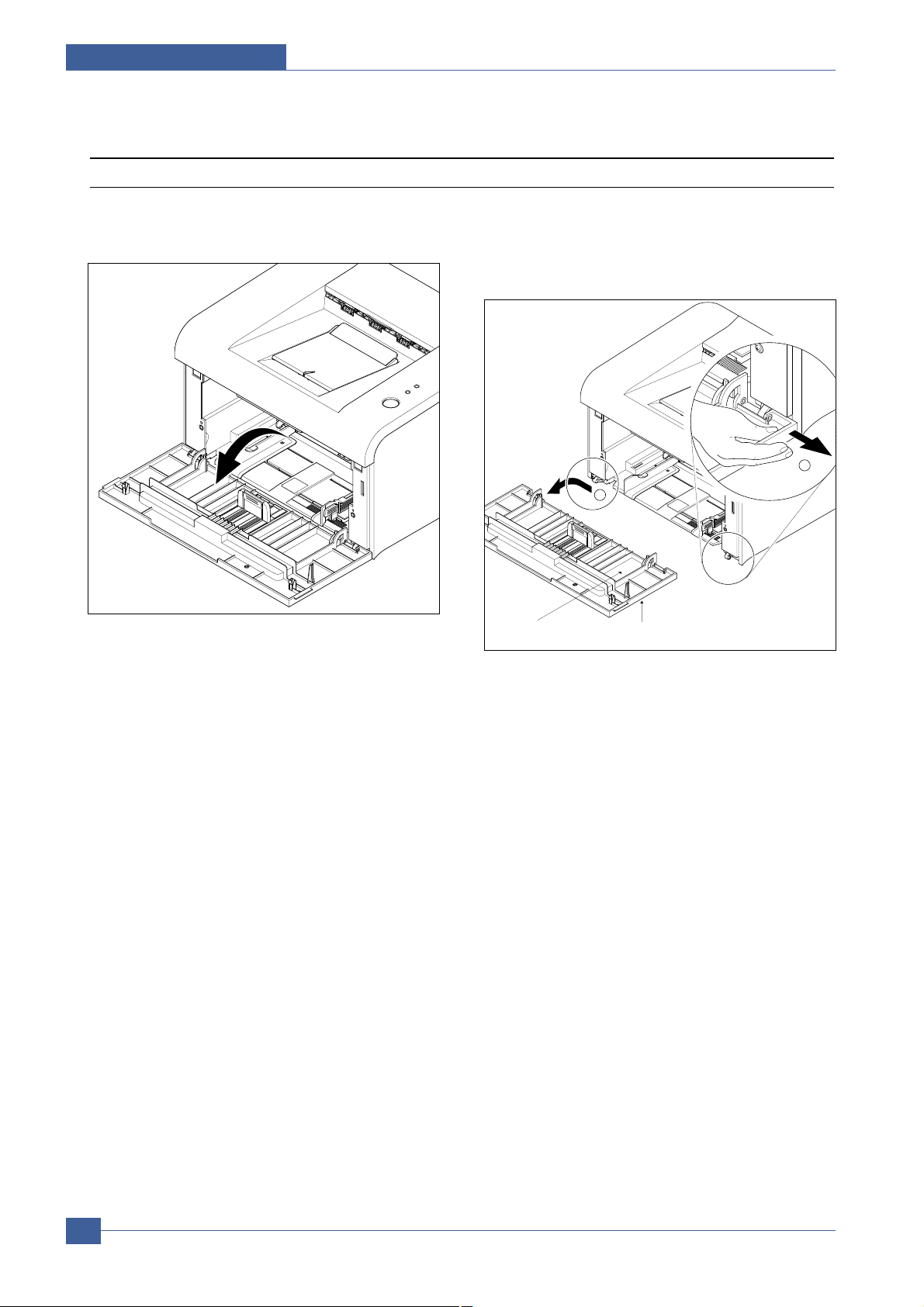
5.2.1 Front Cover
1. Open the front cover.(The front cover and the cassette
tray are assembled with the same assembly.)
2. Separate the cover from the lock of the frame by
pulling the right bottom of the cover toward the arrow
direction. Pull out the front cover to the left as shown
as below.
Front CoverCassette Tray
2
1
Page 3
Disassembly and Reassembly
Samsung Electronics
Service Manual
5-3
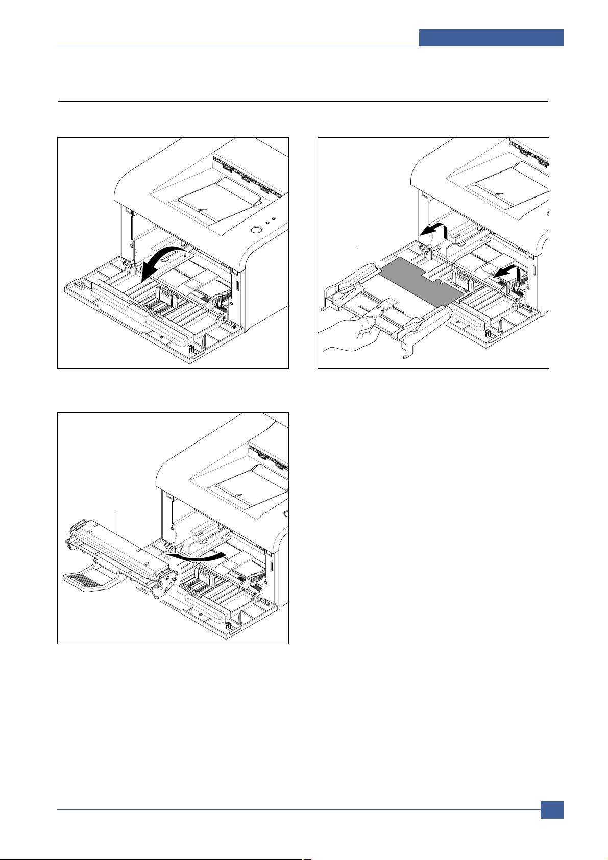
1. Open the front cover.
2. Release the Toner Cartridge.
3. Hold the MP Tray and pull it to the arrow direction.
5.2.2 MP Tray
MP Tray
Toner Cartridge
Page 4
Samsung Electronics
Service Manual
Disassembly and Reassembly
5-4
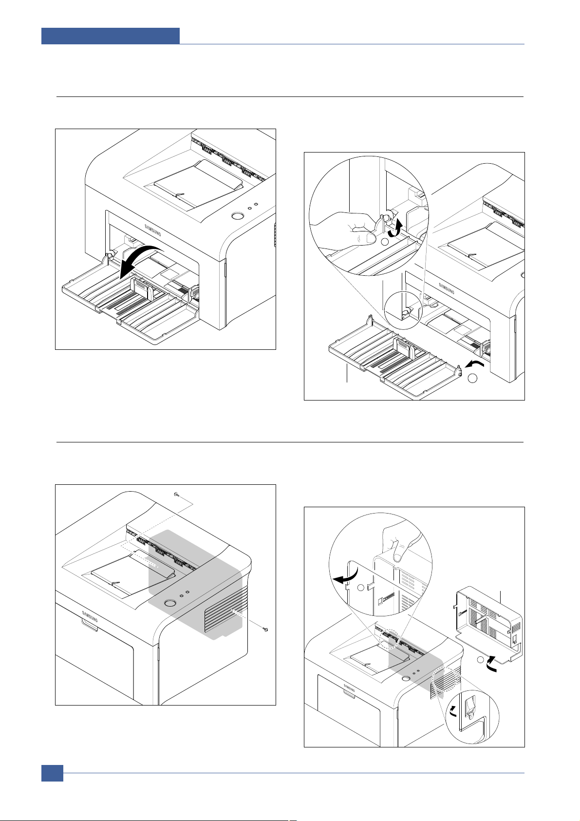
5.2.4 SMPS Cover
1. Release two screws.
(Screw x2:Silver_M3,6003-000196)
2. Separate the lock by holding the left side of the cover
and pulling it toward the arrow direction. Remove it
with carefulness that the power switch is not hooked
on SMPS cover as shown as below.
1.For separating only cassette tray,open the tray. 2. Hold the set and lift up the hook on the left bottom
toward the arrow direction.Separate the cassette tray
by pulling it out to the left as shown as below.
5.2.3 Cassette Tray
1
Cassette Tray
2
1
SMPS Cover
2
Page 5

Disassembly and Reassembly
Samsung Electronics
Service Manual
5-5
5.2.5 Main Cover
1. Before Disassembling.
-Separate the font cover.(Refer to 5.2)
-Separate the SMPS cover.(Refer to 5.3)
2. Release 4 screws as shown as below.
(Screw x 4 : Silver_M3,6003-000196)
3. Hold the both ends of the cover and pull it up bit by bit
toward the arrow direction as shown as below.
4. Separate it by holding the both sides of the main
cover and carefully lifting it up.
5. If necessary,remove the jam cover.Open the cover,
take out the hook on the right toward the arrow direction, and then take out the jam cover to the right side.
Main Cover
Jam Cover
1
2
Page 6

Samsung Electronics
Service Manual
Disassembly and Reassembly
5-6
5.2.6 Top Cover
1. Before Disassembling.
-Separate the font cover.(Refer to 5.2)
-Separate the SMPS cover.(Refer to 5.3)
-Separate the Main cover.(Refer to 5.4)
2. For separating the LED lens and the On-Line key,
release the 5 screws connected to the main cover,
and then 4 locks on the front and rear of the top cover
by using a screw driver.Remove the top cover from
the main cover.
(Screw x 5:Silver_M3,6003-000196)
3. Unscrew 2 screws from the separated top cover as
shown as below,and then separate the LED Lens
from the On-Line key.
(Screw x 1:Silver_M3,6003-000196)
LED Lens
On-Line Key
Top Cover
Main Cover
2
1
Page 7

Disassembly and Reassembly
Samsung Electronics
Service Manual
5-7
5.2.7 HVPS
1. Before Disassembling.
-Separate the font cover.(Refer to 5.2)
-Separate the SMPS cover.(Refer to 5.3)
-Separate the Main cover.(Refer to 5.4)
2. Remove the sheet by releasing the 5 screws which
connects the HVPS and the Sheet.
(Screw x 3:Gold_M3,6003-000269)
3. Separate the HVPS with HVPS ground from the
frame by releasing the remaining 3 screws.
(Screw x 3:Gold_M3,6003-000269)
4. Remove the connector from the separated HVPS.
HVPS Sheet
HVPS Ground
HVPS
Page 8

Samsung Electronics
Service Manual
Disassembly and Reassembly
5-8
5.2.8 RX Drive
1. Before Disassembling
-Separate the font cover.(Refer to 5.2)
-Separate the SMPS cover.(Refer to 5.3)
-Separate the Main cover.(Refer to 5.4)
2. Release 2 screws (Screw x 2:Silver_M3, 6001-
000130) connected to the engine shield and 6 screws
(Screw x 6: Gold_M3,6003-000296)connected to the
frame. Separate the RX drive by pulling it out toward
the arrow direction.
3. Remove the connector from the separated RX drive.
4. After removing the RX drive,RDCN Gear, OPC Gear,
Fuser Gear, and Feed Gear can be removed from the
frame.
5. When separating the motor,remove the motor bracket
first by removing 4 screws as shown as below, and
then remove the 2 screws from the motor bracket.
RDCN Gear
OPC Gear
Fuser Gear
Feed Gear
Please, be careful not to touch the protruding 4 screws at the outside of the RX drive.
Note:
RX Drive
Gear Bracket
RX Motor
Motor Bracket
Page 9

Disassembly and Reassembly
Samsung Electronics
Service Manual
5-9
5.2.9 Fuser
1. Before Disassembling
-Separate the font cover.(Refer to 5.2)
-Separate the SMPS cover.(Refer to 5.3)
-Separate the Main cover.(Refer to 5.4)
2. Separate 2 connectors from the SMPS and the Main
PBA as shown as below.
3. Separate the fuser by unscrewing 4 screws on the
frame. (Screw x 4:Gold_M3,6003-000269)
4. After removing the Lamp Cover L/R, separate the
Fuser Dummy cover.
5. Separate the Exit roller F/Down and the exit gear
(DRV17)by turning the left/right holder connected to
the exit roller F/Down to the arrow direction.At this
time,roller_main,roller_FR, F/Down Holder,and spring
are separated with theses.
Thermister
Fuser
Lamp Cover_R
Fuser Dummy Cover
Lamp Cover_L
Exit Gear
Fuser
Roller_FR
Roller_Main
F/Down Holder
Exit Roller F/Down
Holder
Page 10

Samsung Electronics
Service Manual
Disassembly and Reassembly
5-10
6. Remove the thermo cap by releasing 2 screws as
shown as below.
(Screw x 2:Black_M3,6003-000282)
7. After pulling out the thermostat as shown as below,
remove the CBF harness from its left/right side.
8. Release the screw as shown as below, remove the
harness from the cover, and then pull out the thermistor.
(Screw x 1:Black_M3,6003-000196)
9. After separating the CBF harness connected to the
left/right side of the halogen lamp, release 2 screws
from the halogen lamp.
(Screw x 2:Black_M3,6003-000196)
10. Separate the Cover-M by releasing 2 screws as
shown as below.
(Screw x 2 : Black_M3, 6003-000196)
11. Remove the halogen lamp from the heat roller by
pulling it out to the arrow direction.
Note : Under the condition that the fuser is connected to the frame,the exit roller F/Down can be
separated.However,be careful that the Roller_Main,the Roller_FR,and F/Down Holder could get into the
inner frame due to the spring’ action.
Thermo Cap
Thermostat
Thermistor
Cover-M
Heat Roller
Halogen Lamp
Page 11

Disassembly and Reassembly
Samsung Electronics
Service Manual
5-11
5.2.10 Engine Shield (Including Main PBA and SMPS)
1. Before Disassembling
-Separate the font cover.(Refer to 5.2)
-Separate the SMPS cover.(Refer to 5.3)
-Separate the Main cover.(Refer to 5.4)
2. Disconnect all connectors except the connector which
connects the SMPS to the Main PBA.
3. Release 6 screws as shown as below, separate the
harnesses from the shield,and then separate the
engine shield with carefulness of the actuator feed
sensor lever. (Screw x 6:Silver_M3,6003-000196)
4. For removing only SMPS, perform the follows in order
: separate the SMPS cover (Refer to the 5.3), release
5 screws, separate the fuser connector and the main
PBA connector, and then take out the SMPS.
(Screw x 5 : Gold_M3, 6003-000269)
5. For removing only Main PBA, perform the follows in
order : separate the SMPS cover (Refer to the 5.3),
release 3 screws, separate the main PBAconnector,
and then take out the main PBA.
(Screw x 3 : Gold_M3, 6003-000269)
Thermister
Clutch
Fuser
LSU
Motor
HVPS
Mirco S/W
Engine Shield
(W/Main PBA, SMPS)
SMPS
Main PBA
Actuator Feed Sensor Lever
Page 12

Samsung Electronics
Service Manual
Disassembly and Reassembly
5-12
5.2.11 LSU
1. Before Disassembling
-Separate the font cover.(Refer to 5.2)
-Separate the SMPS cover.(Refer to 5.3)
-Separate the Main cover.(Refer to 5.4)
2. Release 3 screws as shown as below, lift up the LSU,
and then disconnect 2 connectors from the separated
LSU. (Screw x 2:Silver_M3,6003-000196)
LSU
Page 13

Disassembly and Reassembly
Samsung Electronics
Service Manual
5-13
5.2.12 Paper Path Frame
1. Before Disassembling
-Separate the font cover.(Refer to 5.2)
-Separate the SMPS cover.(Refer to 5.3)
-Separate the Main cover.(Refer to 5.4)
-Separate the Fuser.(Refer to 5.8)
-Separate the Engine shield.(Refer to 5.9)
2. After releasing 4 screws as shown as below, take it
out toward the arrow direction with carefulness of
ground and harnesses.
(Screw x 4:Silver_M3,6003-000196)
3. After releasing the 2 hooks from the right side of the
frame,take out the transfer roller.
(Screw x 2:Silver-M3,6003-000196)
4. Remove the solenoid-MP by releasing the screw from
the left side of the frame.
(Screw x 1:Gold_M3,6003-000301)
Paper Path Frame
1
Bush
Transfer Roller
Bush(L)
2
Mirco S/W
Solenoid-MP
Page 14

Samsung Electronics
Service Manual
Disassembly and Reassembly
5-14
5.2.13 Pick_Up Roller
1. For separating the pick-up roller sponge, open the
front cover, and then take out the toner cartridge.
2. While pressing the hooks on the left/right side of the
pick-up housing B, pull out the pick-up housing U as
shown as below.Then,replace the sponge.
Toner Cartridge
1
Housing B
2
Sponge
Housing U
 Loading...