

Page 1
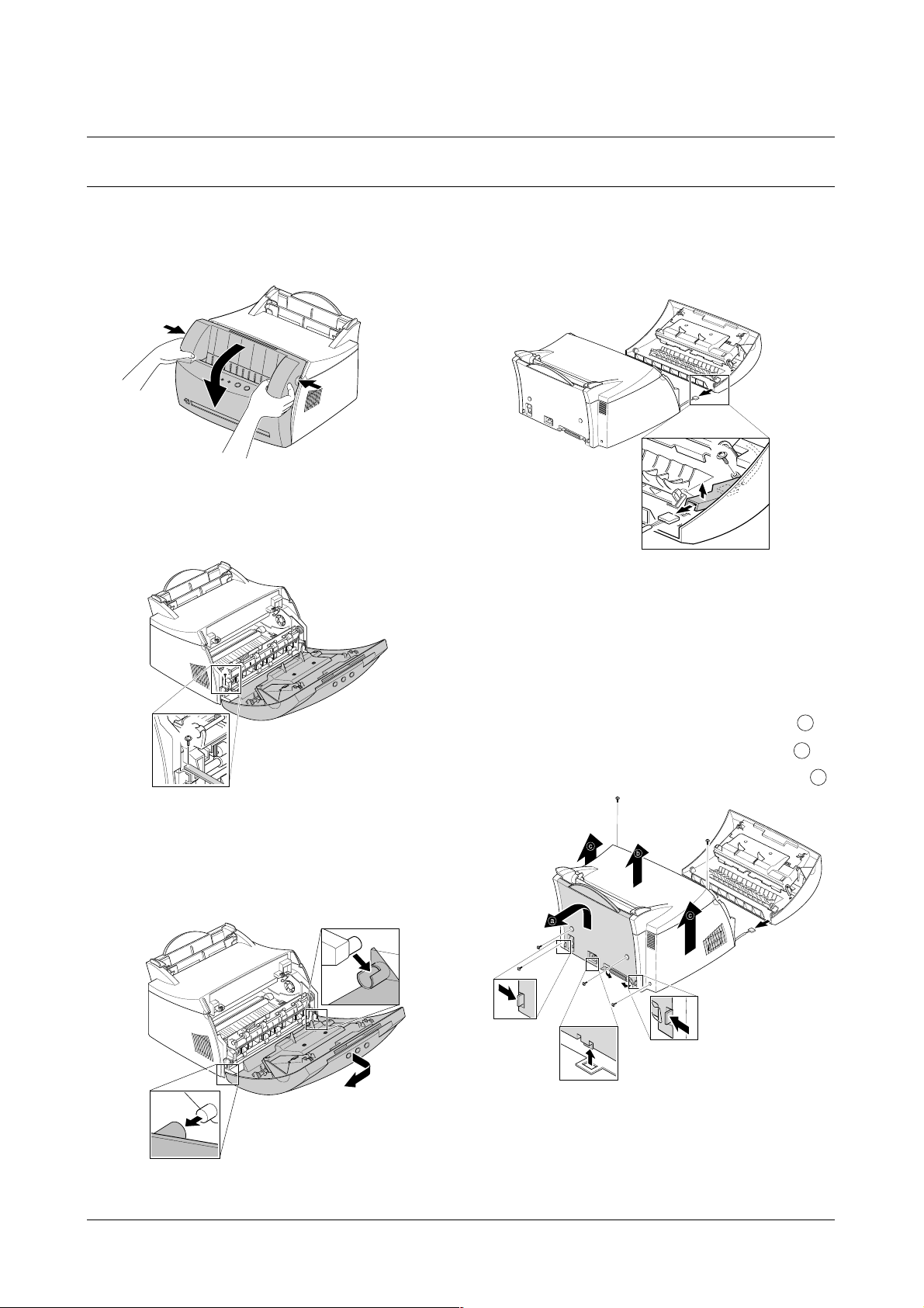
3-1-1 Front Cover
1. Pull the both side of the cover to open.
2. Remove a screw and remove the stopper that holds
the printer cover.
3. Loosen the right lower part of the cover, then push the
cover in the direction of arrow to loosen the left lower
part.
4. Remove a screw of the front cover PCB and remove
the connector, then remove the cover.
3-1-2 Other Covers
1. Before you remove other covers, you should remove the
F
ront cover in advance.
2. Rear Cover : Remove the cover in the direction of .
3. Top Cover : Remove the cover in the direction of .
4. Side Cover L, R : Remove the cover in the direction of .
3-1 Cover Assembly
Disassembly and Reassembly
3-1
Samsung Electronics
3. Disassembly and Reassembly
a
b
c
Page 2
Disassembly and Reassembly
3-2
Samsung Electronics
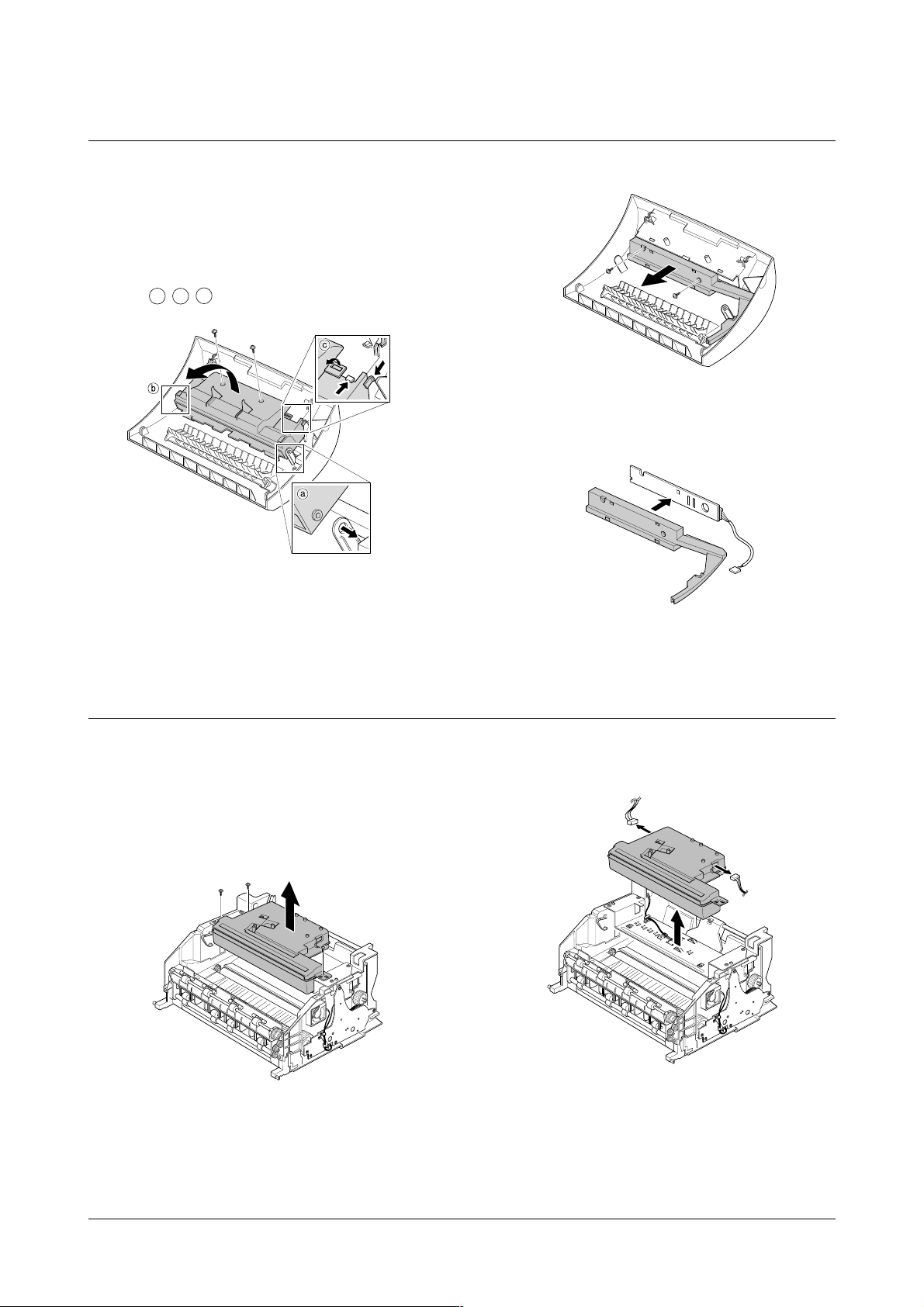
3-2 LED Panel PBA
1. Before you remove other covers, you should remove.
• Front Cover (see [3-1 Main Cover])
2. Remove two screws of PCB cover, and widen the
hooks( ) to remove.
3. Remove two screws, and remove LED panel.
4. Remove PCB from the PCB cover.
3-3 LSU(Laser Scanning Unit)
1. Before you remove LSU, you should remove front
cover, rear cover and top cover.
• Main Cover (see [3-1 Main Cover])
2. Remove three screws securing the LSU.
3. Remove two connectors from the LSU, then remove
the LSU.
a
b
c
Page 3

Disassembly and Reassembly
3-3
Samsung Electronics
3-4 Transfer Roller
1. Open the front cover.
2. Use a proper tool("-" type screwdriver) to pull the one
end of the roller slightly, then take it out.
3-5 Motor Assembly
1. Before you remove the motor assembly, you should
remove:
• Main Cover (see [3-1 Main Cover])
• Shield Engine Assembly
2. Remove five screws securing the motor assembly
and remove a connector from engine board(Engine
board and SMPS board are integrated), then take the
motor assembly out.
Page 4

Disassembly and Reassembly
3-4
Samsung Electronics
3-6 HVPS Board
1. Before you remove HVPS board, you should remove:
•Main Cover (see [3-1 Main Cover])
2. Remove four screws and a connector from HVPS
board, then take the board out.
3-7 Fuser Assembly
1. Before remove fuser assembly, you should remove:
• Main Cover (see [3-1 Main Cover])
2. Remove two ground screws and a connector as illustrated.
3. Remove two screws and unplug a fuser assembly
harness. Then use a " - " screwdriver to unlatch the
fuser assembly to remove.
Note
When you reassemble the HVPS board, make
sure that five terminals should be put in place.
Terminal
Page 5

Disassembly and Reassembly
3-5
Samsung Electronics
3-8 Thermostat and Halogen Lamp
1. Remove a screw from the fuser assembly and
remove the thermostat cover, then remove two
screws securing the thermostat.
2. Remove two screws from the fuser assembly, and
take the Heat Roller out.
3. Take the halogen lamp out from the Heat Roller.
Note
When you reassemble the halogen lamp,
handle it with care as it is fragile.
Page 6

Disassembly and Reassembly
3-6
Samsung Electronics
3-9 SMPS Board
1. Before you remove the SMPS board, you should
remove:
• Main Cover (see [3-1 Main Cover])
2. Remove screws in the order of then remove
the shield engine assembly.
3. Unplug connectors from the main board and connectors from SMPS, then remove the SMPS. Remove
four screws from SMPS and remove the SMPS
board.
Note
The Engine board and SMPS board are
integrated in a body.
a
b
a
b
Page 7

Disassembly and Reassembly
3-7
Samsung Electronics
3-10 Main Board and Sensor Board
1. Before you remove the main board, you should
remove:
• Main Cover (see [3-1 Main Cover])
• SMPS board (see [3-9 SMPS Board])
2. Remove two screws from the main board and unplug
all of connectors, then remove the board.
3. Release four snap-fits securing the insulator engine
board and then remove the insulator.
4. Release four snap-fits securing the sensor board and
then remove the sensor board.
Main B’d
 Loading...