


DMS2.5
(Data Management Server2.5)
MIM-D01AN
MIM-D01AUN
BACnet Gateway
MIM-B17BN
MIM-B17BUN
LonWorks Gateway
MIM-B18BN
MIM-B18BUN
Air Conditioner
user manual
imagine the possibilities
Thank you for purchasing this Samsung product.
E-2
XDo not attempt to install or repair the product by yourself.
XThe product contains no user-serviceable parts. Always consult authorized
service personnel for repairs.
XWhen moving, consult authorized service personnel for disconnection and
installation of the product.
XEnsure that the wall is strong enough to support the weight of the product.
XMust install the product with rated power supply.
XIn the event of a malfunction (burning smell, etc.), immediately stop operation,
turn off the electrical breaker, and consult authorized service personnel.
X Ne tentez pas d’installer ou de réparer vous-même le produit.
X Le produit ne contient aucun composant interne susceptible d’être réparé par
l’utilisateur. Consultez toujours le personnel d’entretien agréé pour toute réparation.
X En cas de déplacement, consultez le personnel d’entretien agréé pour tout
débranchement et toute installation du produit.
X Assurez-vous que le mur est suffisamment résistant pour supporter le poids du produit.
X Vous devez raccorder le produit à une installation supportant sa puissance nominale.
X En cas de dysfonctionnement (odeur de brûlé, etc.), arrêtez immédiatement le
fonctionnement, coupez le disjoncteur électrique et consultez le personnel
d’entretien qualifié.
WARNING
AVERTISSEMENT
CAUTION
ATTENTION
X Do not use inflammable gases near the product.
X Do not spill water into the product.
X Do not operate the product with wet hands.
X Do not install the product in a location where it will come into contact
with the combustible gases, machine oil, sulphide gas, etc.
X Do not press buttons with a pointed thing.
X Do not pull or bend the product cable excessively.
X Do not use the product for other purpose.
X Do not spray an insecticide or other combustible things on the product.
X Do not clean the product with benzene, solvents or other chemicals.
X Do not give a shock to the product or disassemble it by yourself.
X N’utilisez pas de gaz inflammable à proximité du produit.
XNe renversez pas d’eau dans le produit.
XNe manipulez pas le produit si vous avez les mains mouillées.
XN’installez pas le produit dans un lieu où il sera en contact avec des gaz combustibles,
de l’huile de machine, de l’hydrogène sulfuré, etc.
XN’appuyez pas sur les boutons avec un objet pointu.
XNe tirez pas sur le cordon d’alimentation du produit et ne le pliez pas excessivement.
XN’utilisez pas le produit dans un autre but que celui auquel il est destiné.
XNe vaporisez pas d’insecticide ou autre produit combustible sur le produit.
XNe nettoyez pas le produit en utilisant du benzène, des solvants ou autres produits
chimiques.
XN’appliquez pas de choc sur le produit et ne le désassemblez pas non plus vous-même.
Safety Precautions
Consignes de sécurité
x
Before using the DMS2.5, BACnet Gateway, LonWorks Gateway, read carefully these instructions.
x
After reading the instructions, keep this user's manual in a handy and safe place.
If a user is changed, you must hand over the manuals.
x
Never attempt to install the air conditioning system or to move the product by yourself.
x
Avant d’utiliser le DMS2.5, BACnet Gateway, LonWorks Gateway, lisez attentivement ces consignes.
x
Après en avoir pris connaissance, conservez ce manuel d’utilisation dans un lieu sûr et à portée de
main. En cas de changement d’utilisateur, vous devez remettre les manuels.
x
Ne tentez jamais d’installer le climatiseur ou de déplacer le produit par vous-même.
English
Français
E-3
Contents
X GENERAL DESCRIPTION ....................................................... 4
X VIEWING THE PARTS ........................................................... 6
X BEFORE USE ...................................................................... 8
X MAIN FUNCTION ............................................................. 10
X STARTING DMS2.5 ........................................................ 14
X CONTROL AND MONITORING ............................................. 20
X ZONE MANAGEMENT ....................................................... 67
X SCHEDULE ..................................................................... 72
X EHP POWER CONSUMPTION INSPECTION ............................ 85
X CONTROL LOGIC MANAGEMENT ........................................ 96
X SYSTEM SETTINGS ......................................................... 109
X CHECK BEFORE USING PANEL .......................................... 161
X SETTING NETWORK INFORMATION .................................... 162
X CHECKING INDOOR/OUTDOOR UNIT INFORMATION ............ 164
X CHECKING DMS2.5 VERSION ........................................ 165
X DATA BACK UP SETTING .................................................. 169
X CHECKING ERROR INFORMATION ...................................... 170
X RESET PASSWORD ......................................................... 171
X BUTTON LOCK .............................................................. 172
X SAFETY HALT ................................................................ 173
X TROUBLESHOOTING ....................................................... 174
X SPECIFICATIONS ............................................................ 176
X LICENSE ....................................................................... 177
Note
X The contents and pictures used in this user manual
may be changed without advance notice for the
functional reinforcement and improvement of a
product.
This System is strictly restricted to authorized user.
Any illegal access shall be punished with a related-law.
E-4
General Description
The DMS2.5 is an Ethernet based device for central management of Samsung system airconditioners. It operates 24 hours without a separate management (PC).
Introduction of DMS2.5 (Data Management Server2.5)
The DMS2.5 provides the following advantages:
X Everyday Device–The DMS2.5 is operational all year long 24 hours.
X
Independent Operation–The DMS2.5 can operate schedule control and power
distribution without a PC.
Note In order to run power distribution, relevant controllers need to be installed.
X Remote Control
Web – The DMS2.5 has a built-in web server function and can be accessed from a
remote location to operate status
monitoring, control, trouble history, and schedule setting of the system
air-conditioners.
Using an Upper Level Controller–When a separate upper level controller (S-NET
series) is used, a number of DMS2.5 can be controlled with one central management
system.
X Data Storage–The DMS2.5 has its own database built-in, therefore, trouble history,
indoor unit installation information, and power distribution data can be saved and
retrieved.
X Large Scale Management–At most 256 indoor units can be connected to one DMS2.5
and therefore, only one DMS2.5 can manage small and medium size buildings.
X Automatic ”e-mail” sending–When an error is occurred, inform the error details to an
e-mail saved on DMS2.5.
Advantages of DMS2.5 System
Note
X Please be advised that once you are permitted access
to the system, you will be deemed to have consented
to having software relating this system automatically
updated or modified on a periodic basis. You will be
deemed to have consented to having software relating
this system automatically updated or modified on a
periodic basis.

E-5
X DMS2.5: The abbreviation of Data Management Server2.5.
X Upper Controller: S-NET 3, RMS and DMS2.5 which allows controlling by accessing to a
web page.
X OnOff Controller: A device that controls 16 groups of the DVM air conditioner.
A central control device of a DVM system which is located between a
D
MS2.5 and an outdoor unit.
X AHU(Air Handling Unit): Executes heat exchange between air and cooling unit using
central air conditioning duct method.
X ERV(Energy Recovery Ventilator): Ventilating system using heat recovery function.
Terms
E-6
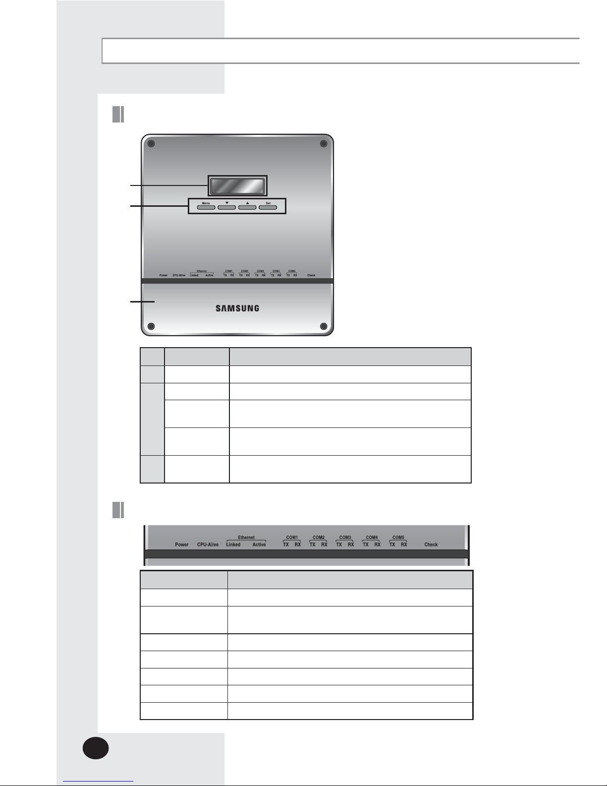
Viewing the Parts
Front View
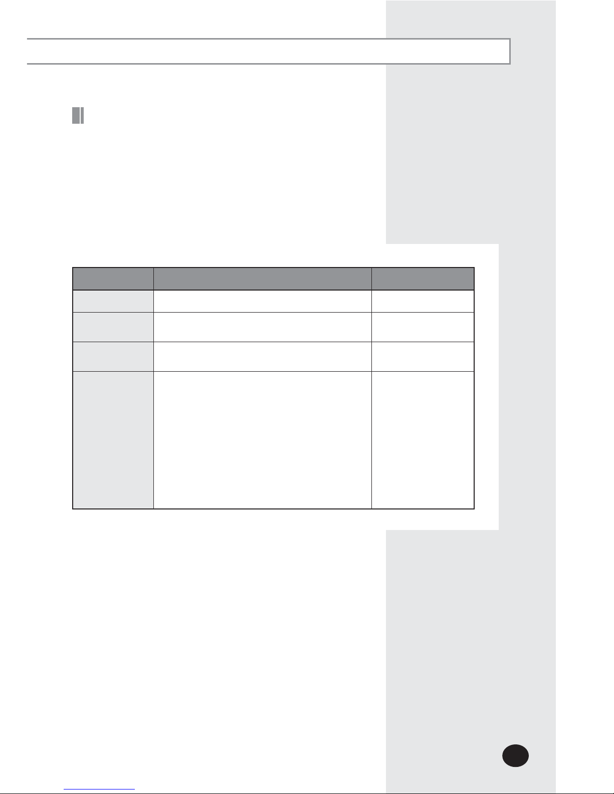
No. Name Description
LCD Display Display current time/ Check menu
Menu button Access to main menu
▼/▲ button
Select the function you want and set detailed functions in
main menu
Set button
Check the function you want from main menu
and select it
Bottom cover
Unfasten 2 screws on the bottom and separate the bottom
cover from DMS2.5. Then check cable connection part.
Name Description
Power Turns blue when the power is supplied.
CPU Alive
Blinks in orange with 1 second intervals during normal
operation.
Ethernet–Linked Turns green during normal connection.
Ethernet–Active Blinks in orange during normal transmission/reception.
COM1~5 – TX Blinks in green during normal transmission.
COM1~5 – RX Blinks in green during normal reception.
Check Turns green when notice occurs.
Indicator
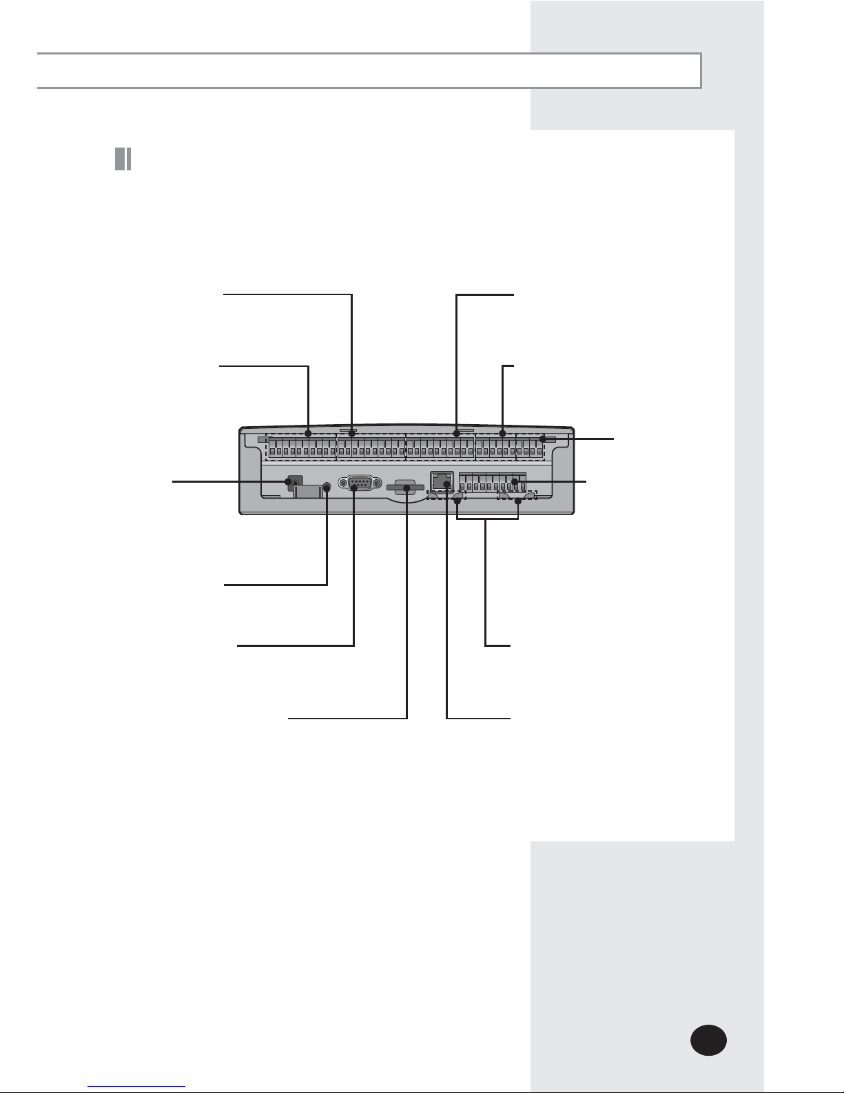
E-7
DI Terminal1
Connect Digital Input
- Channel 1~Channel 5
DI Terminal2
Connect Digital Input
- Channel 6~Channel10
DO Terminal 2
Connect Digital Output
- Channel 6~Channel 8
DO Terminal1
Connect Digital Output
- Channel 1~Channel 5
Power
Terminal
Connect
DMS2.5 adapter
Reset Button
Reset DMS2.5
RS485
Communication
terminal
Connect for RS485
communication with
devices such as OnOff
Controller/Outdoor
unit
- COM1 ~ COM5
Cable tie groove
Arrange cables connected to
DMS2.5
LAN Terminal
Connect LAN cable
Serial Terminal
Service agent checks error
status
SD Card Socket
Socket for sub memory (SD or MMC)
(
Sub memory is for DMS2.5 program
update and set information saving)
※ Purchase SD card separately.
X Separate bottom cover by unfastening 2 screws on the bottom.
Bottom View
Reserved
E-8
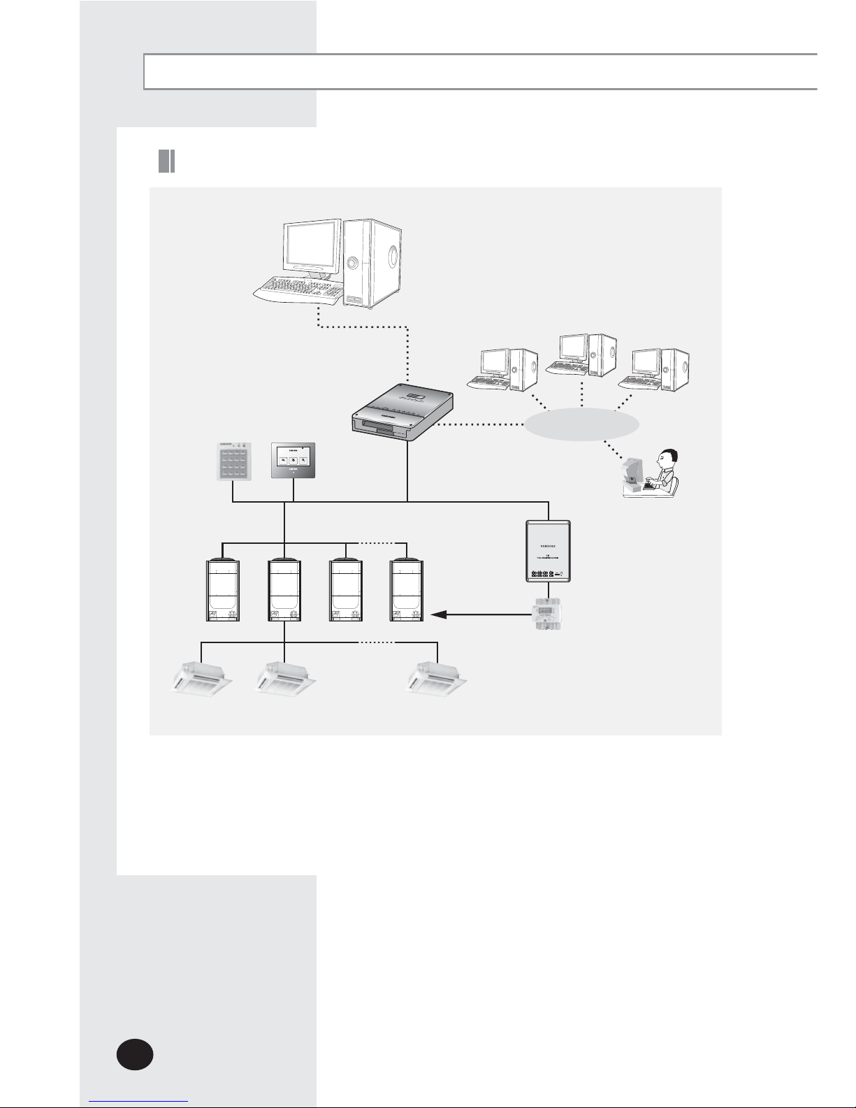
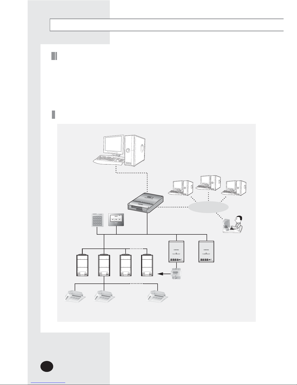
X Connecting outdoor unit and DMS2.5
- You can control up to 80 outdoor units and 256 indoor units by using DMS2.5.
※
You can connect up to 16 (outdoor) units per each communication channel of the
DMS2.5.
-
If the number of connected outdoor unit increases, it may take long time for tracking.
(Max. 30 minutes)
PM 05:45
OnOff
controller
DMS2.5
Internet
Web Client
RMS Senter
S-NET 3
TCP/IP
R5 485
(DVM Series)
Outdoor Unit
Max 256
Indoor units
SIM/PIM
Power meter
Before Use
System Configuration
Touch
Centralized
controller
E-9
XWindows 7 or later version
XInstall Internet Explorer 11 or later version
XInstall Silverlight 2.0 or later version
Web Browser Specification
Note
X Visit internet homepage (http://www.microsoft.com/silverlight/) to download
Silverlight. Or you can download it through the download link which is noticed
automatically when the PC is connected to the Internet and you access to DMS2.5
for the first time.
X Silverlight operates normally with Windows 7 or later version.
It may not operate normally with former version of Windows.
All settings of DMS2.5 will be arranged in web page which built in DMS2.5.
You should access to DMS2.5 IP to use DMS2.5 web page.
There are 2 ways to access DMS2.5 IP.
(For about settings, refer to installation manual.)
X Static IP setting
X Dynamic IP(DHCP) setting
X Basically, only Private IP can be set to IP address. To use Public IP, you must set Enable
public IP as ‘Enable’ from the menu [System Settings]
£
[System environment setting].
- Private IP range: 10.0.0.0 ~ 10.255.255.255, 172.16.0.0 ~ 172.31.255.255,
192.168.0.0~192.168.255.255
Computer Settings for DMS2.5 Connection
X
For devices that support new communication, you must set the communication mode
of the channel to 'NEW' from [System settings £ Tracking] menu. Set of Indoor/outdoor
units, with conventional communication type, cannot be connected to DMS2.5 with new
communication.
X
When 'NEW' is set as communication mode of the channel, virtual OnOff controller
address will be assigned.
(Channel 0: Virtual OnOff controller 11, Channel 1: Virtual OnOff controller 12,
Channel 2: Virtual OnOff controller 13, Channel 3: Virtual OnOff controller 14,
Channel 4: Virtual OnOff controller 15)
X
The maximum number of indoor units that can be connected to each communication
channel of DMS2.5 RS485 is 128.
X
Use this product only in a separate dedicated network.
Samsung electronics is not liable for any problems caused
by connecting it to the Internet or an intranet.
E-10
Device Type
Indoor Unit
Indoor unit communication error
Indoor unit sensor related error
Other errors
Outdoor Unit
Outdoor unit communication error
Pipe inspection error
Outdoor unit sensor related error
Outdoor unit related other errors
Communication error
such as OnO controller
Control device related communication
error
Main Function
The DMS2.5 saves at most 1024 cases of trouble history.
If the number of errors exceeds 1024, only the latest 1024 cases
a
re stored by deleting the oldest trouble history.
X Device name, address, error occurrence time, error solvation
time, trouble history will be saved. You can check it in web
page or upper controller.
X When an error occurs, it sends trouble history to e-mail saved
in DMS2.5.
X Some functions available on DMS2.5 web page may not be
functional at BACnet Gateway and Lonworks Gateway.
For detailed function, refer to the installation manual or
contact Samsung Electronics.
Save Trouble History
The DMS2.5 receives/manages setting and control data from the
upper level controller and sends the received data to the lower
level system.
X
Upper controller: S-NET 3, RMS and DMS2.5 which allows
controlling by accessing to a web page.
X
S-NET 3: System air conditioner controlling and monitoring
program that is used by installing on a PC.
X
RMS: A device which supervises operation status and break
down status by connecting to DMS2.5 for system air
conditioner remote service. If break down is detected,
it notifies service agent and makes fast service possible.
Interface with Upper Level Controller
E-11
Item Content Remark
Schedule Period Starting and ending date of a schedule
Exception Day
Setup
Set an exception day within a schedule period to
ignore the schedule control
Devices to
be applied
Select devices to receive schedule control
Event
Set indoor unit operation modes
- Device On time
- Device O time
- Desired temperature
- Operation mode: Auto/Cool/Dry/Fan/Heat/O
- Remote control usage Enable RC/ Disable RC/
Cond.RC
- Fan speed: Auto/Low/Mid/High/Turbo
- Air ow: None/Vertical/Horizontal/All
- ERV operation mode: Auto/HeatEx/ByPass/Sleep
- ERV Fan speed: Low/High/Turbo
Weekly Repeat:
Maximum 10 events
per day
Daily Repeat:
Maximum 70 events
The schedule function of the DMS2.5 can be set through the Web
or using the upper level controller. 1day/Everyday/Every week
schedules can be set.
X Each schedule can be used selectively by using the run
schedule/stop schedule order.
X At most 256 schedules can be set.
X Indoor unit control is possible at least 1 minute of interval by
set schedule.
Set and Run Schedule
E-12
System Architecture
The DMS2.5 calculates and distributes the power consumed by each indoor unit by
receiving the total power usage from the watt-hour meter interface modules (SIM/PIM)
and taking into account the operation status of the indoor units.
The DMS2.5 saves at most 1 year of data. After a year, the oldest data is deleted and
the latest data is saved. This data can be checked through the built-in Web page of
the DMS2.5 or by S-NET 3.
Save Integrated Power Distribution Data
Main Function (Continued)
PM 05:45
OnOff
controller
DMS2.5
Internet
Web Client
RMS Senter
S-NET 3
TCP/IP
R5 485
(DVM Series)
Outdoor Unit
Max 256
Indoor units
Power meter
SIM
/PIM
SIM
/PIM
Touch
Centralized
controller
E-13
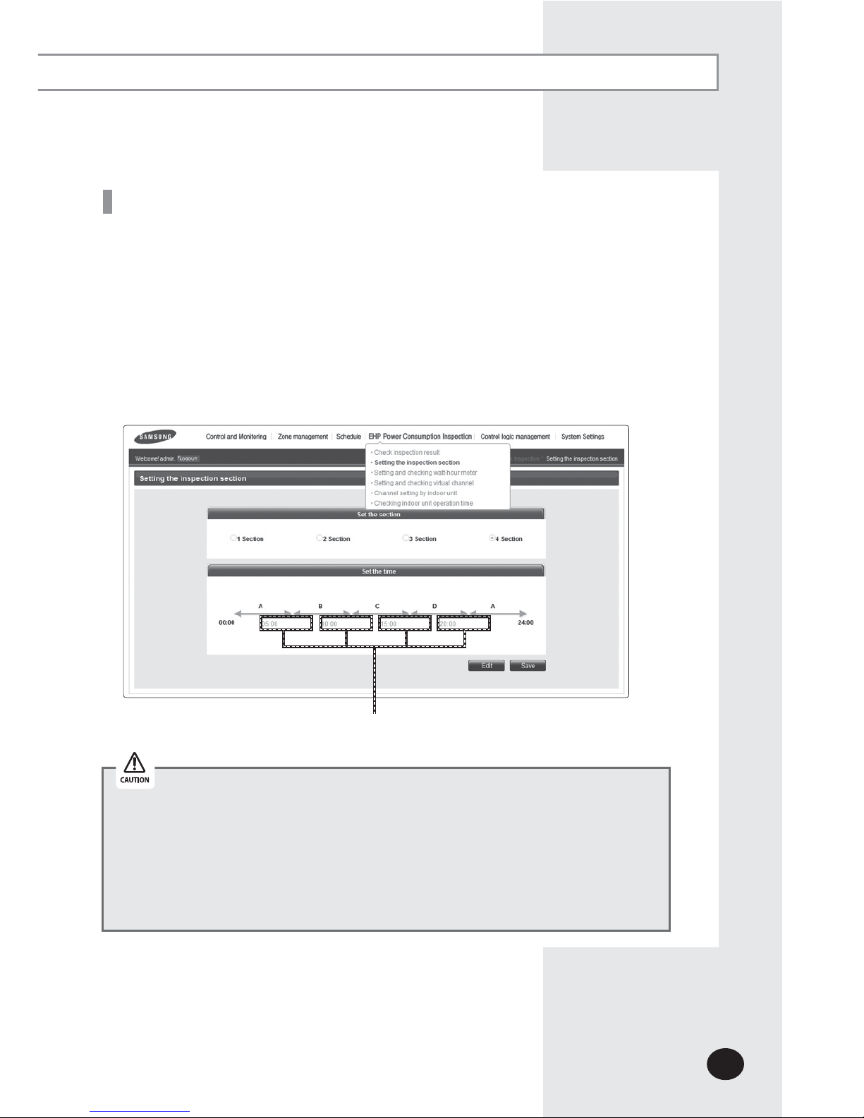
X Time segmentation is used to divide 24 hours into different sections and to distribute
power according to each section.
X
This function is used when the power consumption fee is different according to
different time slots or when a building is charged differently depending on the
consumption time.
X
1 section (A) is set as 24hours, and the factory default setting is set as 1 section.
The time, 24hours, can also be divided into 2 sections (A,B,A), 3 sections (A,B,C,A) or
4 sections (A,B,C,D,A)
X
DMS2.5 shows the result of the power distribution for each section you set.
Input manually (When setting 2 sections, 3 sections, and 4 sections)
Time Segmentation
If communication error occurs between DMS and the lower level controllers,
actual power consumption and the result of power distribution value may not be
same. Make sure to solve communication error status.
- Example of communication error :
Communication error between DMS2.5 and
SIM(PIM)/SIM(PIM) and watt hour meter/
DMS2.5 and outdoor unit/indoor and outdoor
units.
E-14
Set the current time of DMS2.5 system.
X “2016/01/01 01:01:01” is factory setting. Set the current time as DMS2.5 system time.
You can set DMS2.5 time in [System Settings] [System environment setting]
(Refer to page 129~130)
Starting DMS2.5
Current time setting
Connecting devices
(1) Make sure the connection of communication cables(R1/R2) between DMS2.5 and other
devices such as outdoor units, control devices.
(2) E
xecute tracking.
X DMS2.5 communicates with outdoor unit and brings information about installed
indoor unit and outdoor unit.
X
After tracking, you can use indoor unit control and other menu.
X
For tracking, refer to [System Settings] [Tracking] (Refer to page 148~152)
Connecting OnOff controller & outdoor unit
Starting DMS2.5
Access to DMS2.5 & Login
Address bar
If DMS2.5 time does not set as the current time, DMS2.5 may cause malfunction
when using Schedule or control logic management.
E-15
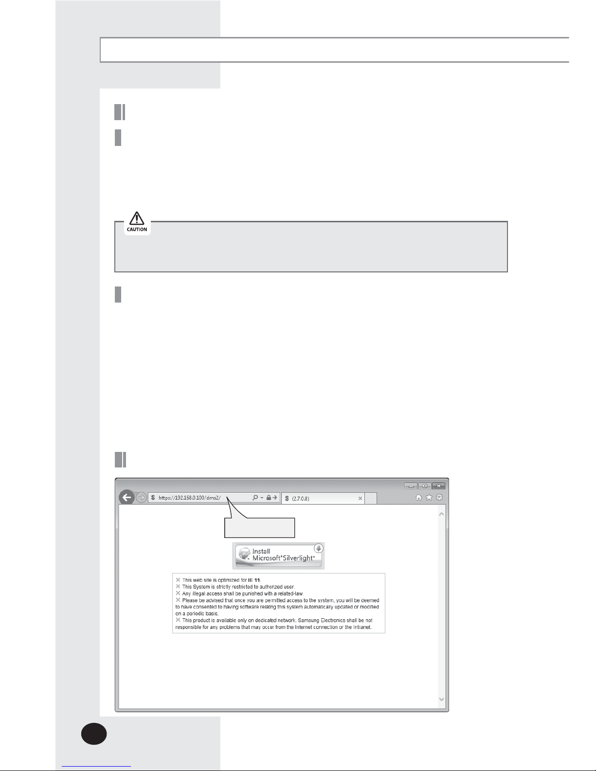
1
Run internet explorer on your computer.
2
Enter IP address (https://192.168.0.100) on the address bar, and then press [ENTER].
X
If it is the first access to DMS2.5, “Install Microsoft Silverlight” message will be
displayed.
-
The message will not appear if Microsoft Silverlight have already installed.
If the message window and login screen does not appear, check PC setting status.
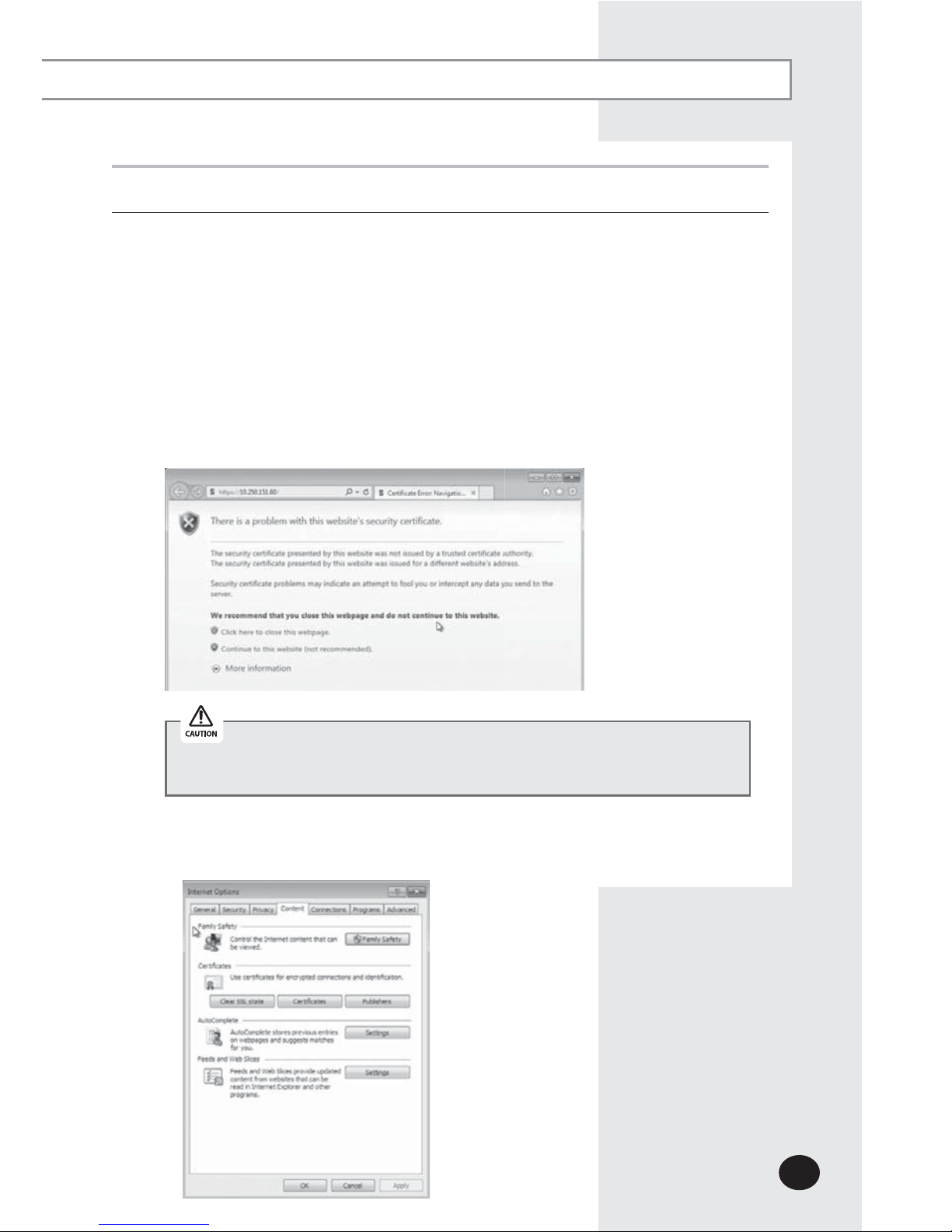
1
) At initial access, security certificate warning popup message will appear as shown.
This message appears since DMS2.5 used the certificate of its own, so it will not
appear if DMS2.5 certificate is registered on web browser. DMS2.5 certificate
must be registered because the message will appear every time and it is not safe
for security if it is not registered. Also, it should be registered to all PCs that are
connecting to DMS2.5.
You must stop connecting due to security problem if the message appears
even if you registered DMS2.5 certificate.
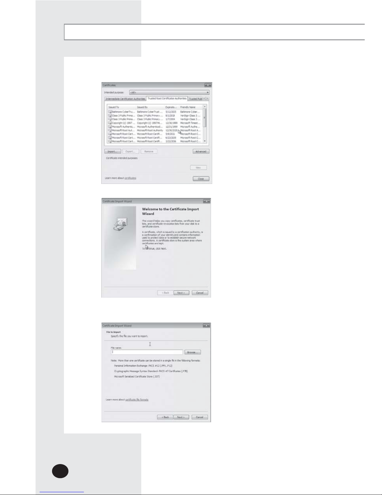
2) Registering DMS2.5 certificate on web browser
A. Select ‘Content’ tap in ‘Tools’
£
‘Internet options’, and click ‘Certicates’.
E-16
B. Select ‘Trusted Root Certication Authorities’ and click ‘Import’.
C. Click ‘Next’.
D. Select ‘Browse’ and nd DMS2.5 certicate, and click ‘Next’. DMS2.5 certicate can
be downloaded from [System environment setting].
Starting DMS2.5 (Continued)

E-17
E. Select ‘Place all certicates in following drive’ and click ‘Next’.
F. Click ‘Finish’, and click ‘Yes’ when security warning appears.
3
Click [Run] and continue installation.
X Access to DMS2.5 again after installation.
E-18
Starting DMS2.5 (Continued)
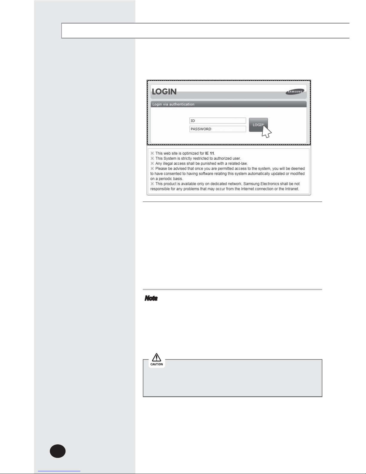
4
Enter ID and password when DMS2.5 main web page
appears.
Then click [LOGIN].
X
The default DMS2.5 user ID is 'admin' and password is
'ac0530'.
X
Depending on authorization settings which set by the
administrator, access to some functions may be restricted.
X To edit user authorization, refer to [System Settings]
[User authorization management]. (Refer to page 112)
Note
X Only authorized users can access to web page.
X Fewer than 5 concurrent users are recommended
because connection speed may slow down.
X DMS2.5 manager should change ID and password for
security and management. (Refer to page 110)
X Logout: To log out, click [LOGOUT] on the top of the
menu.
Silverlight will run normally with Windows 7 or later version.
With former version of Windows, DMS2.5 may not operate
normally.
4
E-19
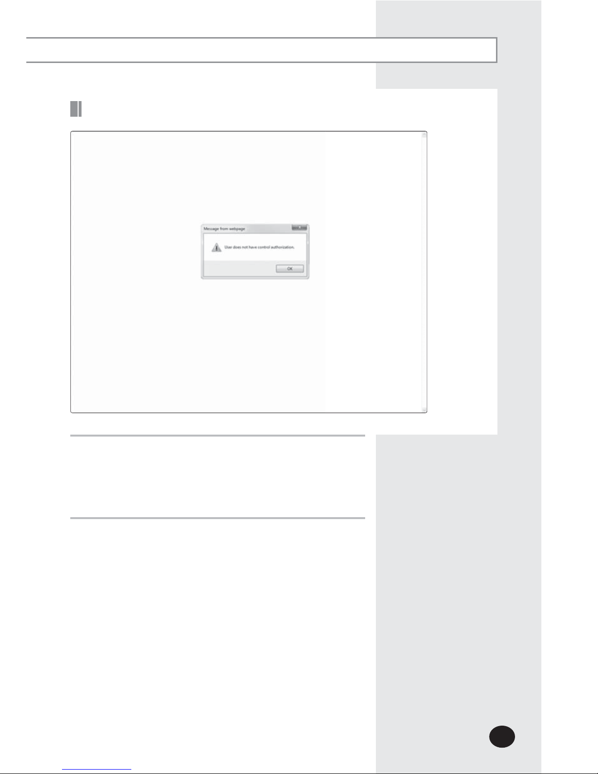
Logged-in User with No Authorization
1
When the screen above appears, ask for manager.
XDepending on control authorization setting, there can be
a user who does not have control authorization.
X
Above screen will appear when the logged-in user does
not have control authorization.
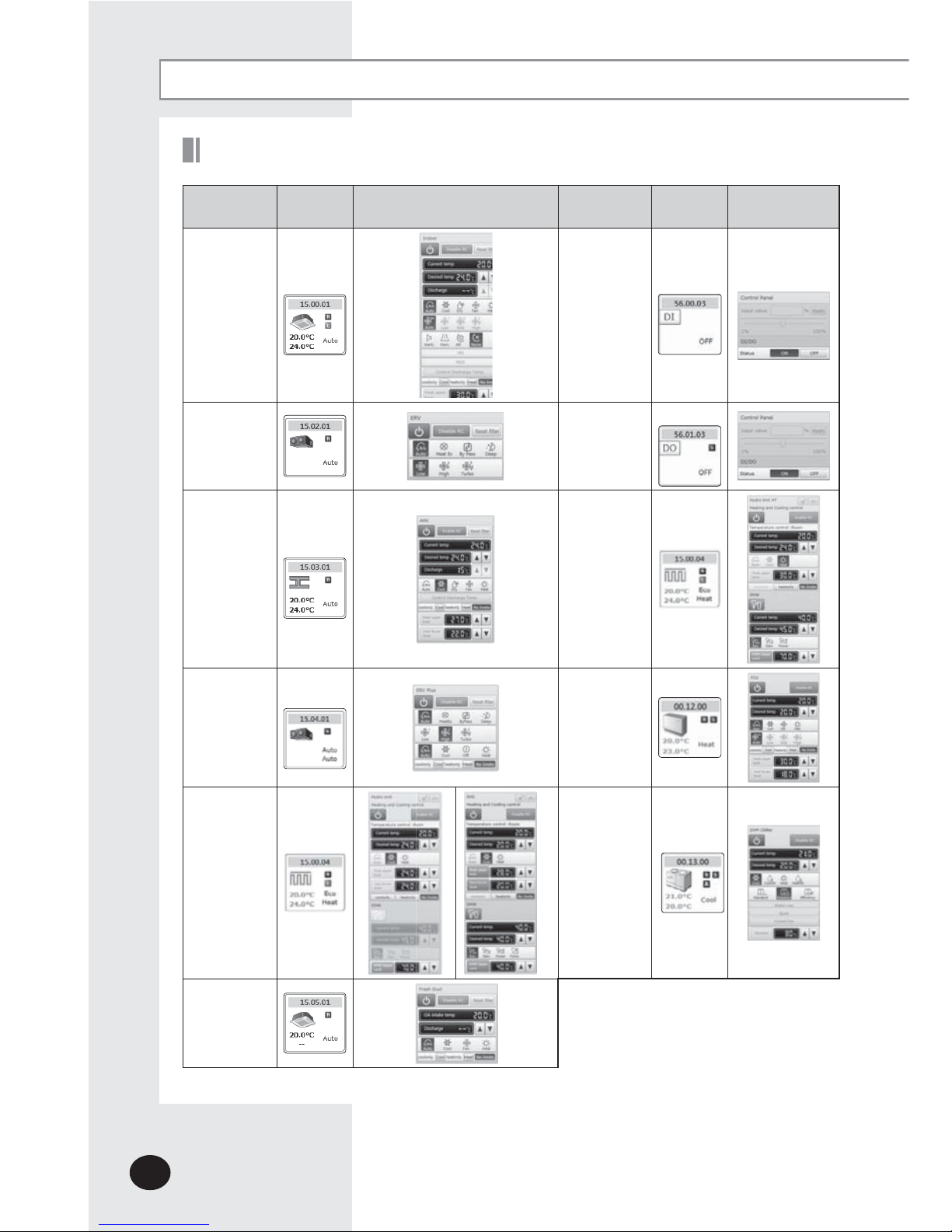
Devices controlled and monitored by DMS2.5
Control and Monitoring
Type Display
Remote controller
(Controlling range)
Type Display
Remote controller
(Controlling range)
Indoor
unit
display
i
con
DI
(Digital
I
nput)
display icon
ERV
display
i
con
DO
(Digital
O
utput)
display icon
AHU
display
i
con
Hydro Unit HT,
display icon
ERV PLUS
display
icon
FCU Kit
display
icon
Hydro
Unit,
Single EHS
display
icon
DVM CHILLER
display icon
Fresh duct
display
icon
E-20
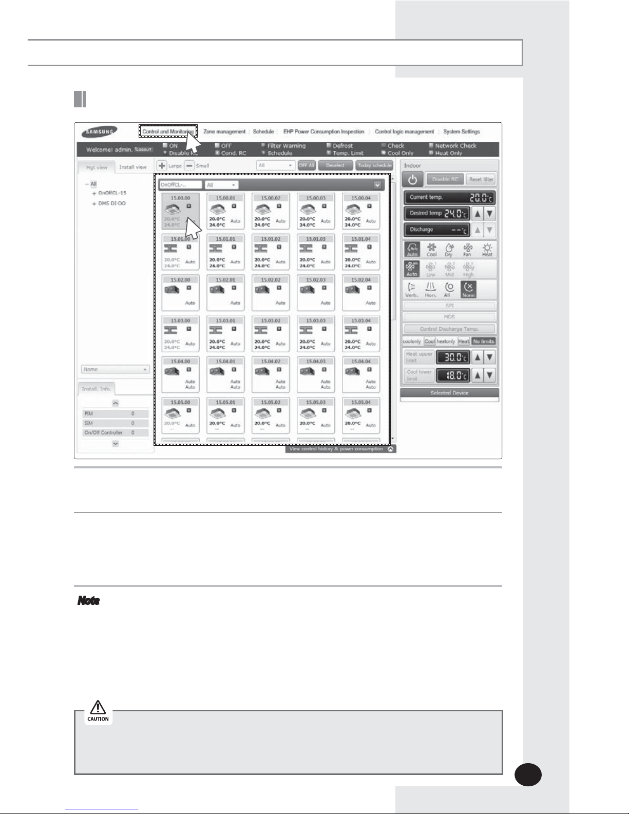
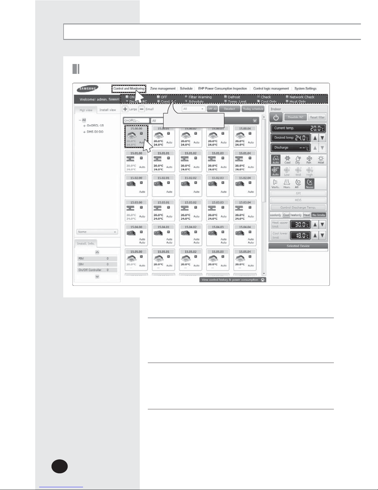
Monitoring Indoor Unit Operation Status
1
1
Click [Control and Monitoring] when DMS2.5 web page menu screen appears.
X [Control and Monitoring] screen will appear when you log-in to DMS2.5 web page.
2
Check the current status of all devices.
X You can check the current controlling status of all installed indoor units, ERV, AHU,
ERV PLUS, Fresh duct, Hydro Unit, Hydro Unit HT, Single EHS, DVMCHILLER, FCU Kit
a
nd other devices.
Note
X When the advanced functions (such as Sleep mode, Energy saving function)
are selected through wired/wireless remote controllers or indoor unit panel,
set operation mode on the remote controllers and DMS2.5 may be displayed
differently. Also, when controlling by DMS2.5, additional functions will be
canceled.
X
Depending on the model of indoor unit, Horizontal/All air flow direction control
may not be possible. In this case, vertical or fixed flow will be displayed depending
on indoor unit’s basic operation specification.
2
Some functions available on DMS2.5 web page may not be functional at BACnet
Gateway and LonWorks Gateway. For detailed function, refer to the installation
manual or contact Samsung Electronics.
E-21

E-22
Controlling an Indoor Unit
Control and Monitoring (Continued)
1
Click [Control and Monitoring] when DMS2.5 web page
menu screen appears.
X
[Control and Monitoring] screen will appear when you
log-in to DMS2.5 web page.
2
Select an indoor unit to control.
X
Check the indoor unit status through status display window.
X When the selected indoor unit is switched on, the remote
controller panel will be automatically activated.
3
Turn the indoor unit on by clicking [ ].
X
Remote controller panel will be activated.
1
Status display window
3
2
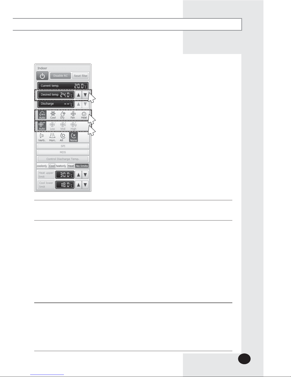
4
Select the operation mode.
X You can select Auto, Cool, Dry, Fan and Heat operation mode.
5
Click [S][T] to set the desired temperature.
X
Each time you press the buttons, the temperature will be adjusted by 1 or 0.1°C (or by 1°F).
X If Auto/Cool/Dry mode is in operation, you can adjust the desired temperature in
the range of 18°C(64°F)~30°C(86°F).
X
If Heat mode is in operation, you can adjust the desired temperature in the range of
16°C(61°F)~30°C(86°F).
X
You cannot adjust the desired temperature in Fan mode.
X When the operation mode of an indoor unit is Cool or Dry mode, you cannot set the
desired temperature lower than lower limit temperature if lower limit is enabled.
X
When the operation mode of indoor unit is Heat mode, you cannot set the desired
temperature higher than upper limit temperature if upper limit is enabled.
6
Select the fan speed.
X You can select Auto, Low, Mid and High.
X If Auto/Dry mode is in operation, fan speed will be set as Auto fan speed.
X If Fan mode is in operation, you cannot select Auto fan speed.
X When the Turbo fan speed is available, the Turbo icon is displayed and you can
select and control the Turbo fan speed.
E-23
5
4
6
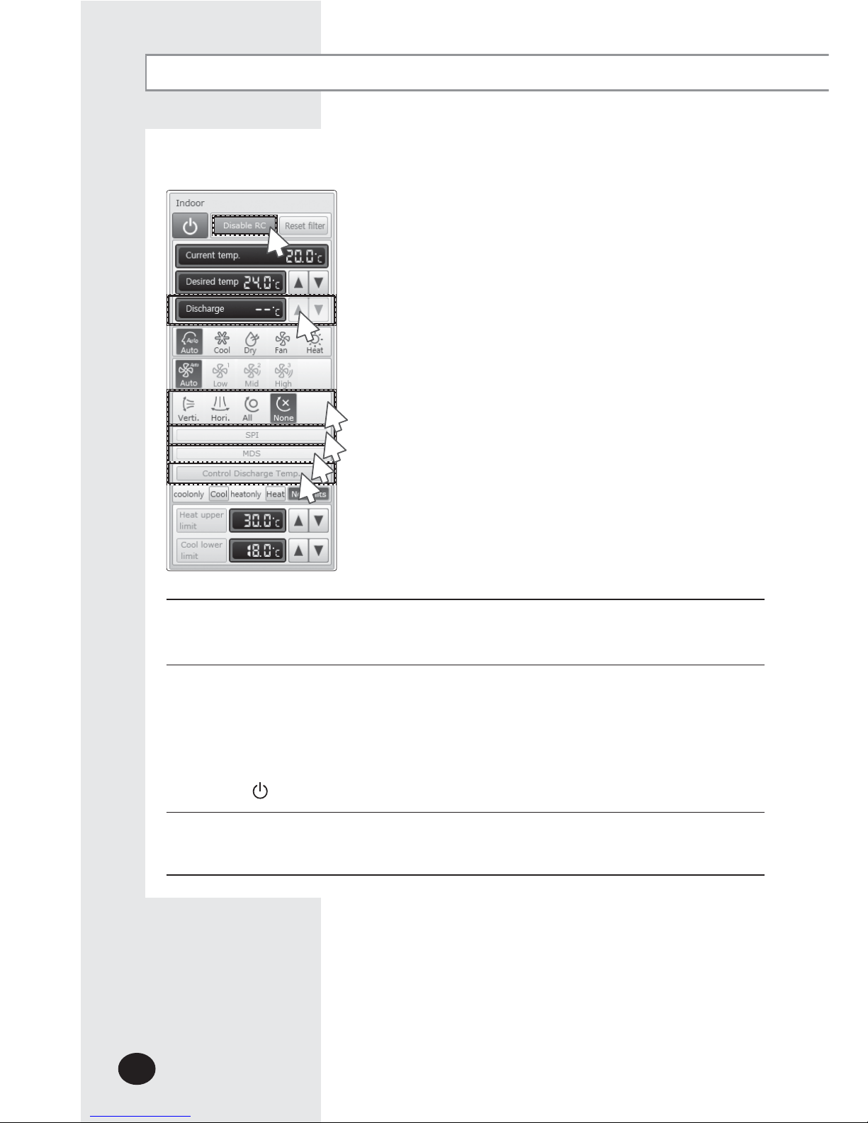
Control and Monitoring (Continued)
7
Select the air flow.
X You can select Vertical, Horizontal, All and None air flow direction.
8
Set remote controller settings.
X You can select Enable RC, Disable RC, and Cond. RC.
X When selecting [Disable RC], indoor unit control by wired/wireless remote controller
and indoor unit panel is not possible. Indoor unit control is only available in
DMS2.5 web page.
X
Click [
] when you want to use wired remote controller in each room.
9
Select SPI setting.
X You can set SPI through button activation / non activation.
E-24
8
7
9
10
11
12
E-25
10
Select MDS setting .
X You can set MDS(Motion Detection Sensor) through button activation / non
activation.
11
Set cooling/heating discharge temperature by clicking [S] and [T].
X When the indoor unit is in Cool mode, you can adjust cooling discharge temperature
and when the indoor unit is in Heat mode, you can adjust the heating discharge
temperature.
X
When the indoor unit is in Auto, Dry or Fan mode, you cannot adjust the discharged
temperature.
X
Cooling discharged temperature can be set in the range of 8°C(46°F)~18°C(64°F).
X Heating discharged temperature can be set in the range of 30°C(68°F)~43°C(109°F).
12
Select [Control Discharge Temp].
X You can enable/disable button to decide whether to use discharge temperature
adjustment.
Note
When filter warning sign is displayed on indoor unit status window
Select the indoor unit and click [Reset filter].
Filter warning will be released.
X Make sure that each indoor unit must be turned on to control.
X Selecting remote controller, reset filter, operation mode limits, setting lower/upper
temperature limit are possible even if the power of indoor unit is off.
X Some air flow direction option may be restricted depending on the indoor unit
model.
X SPI, MDS and discharge temperature functions can be operated normally when
corresponding optional functions are installed to the selected indoor unit.

E-26
Control and Monitoring (Continued)
Indoor Unit Operation Mode Limit
You can monitor the operation status of all indoor units or
have individual or whole control of the indoor units.
1
Click [Control and Monitoring] when DMS2.5 web page
menu screen appears.
X
[Control and Monitoring] screen will appear when you
log-in to DMS2.5 web page.
2
Select an indoor unit to control.
X Check the indoor unit status through status display
window.
X
When the selected indoor unit is switched on, the remote
controller panel will be automatically activated.
1
2
Status display window

E-27
3
3
Set operation mode limit.
X
You can select [coolonly (Cool)], [heatonly (Heat)], and [No limits].
- No limits : You can use cool mode and heat mode with no limits.
Note
X Operation mode limits setting is not available in ERV and DVM CHILLER.
X
If you set the operation mode limit, DMS2.5 will automatically change the
operation mode limit setting of all the indoor units connected to same outdoor
unit.
X
If the indoor unit is cooling only model, you cannot set the operation mode limit to
'heatonly'.
E-28
Control and Monitoring (Continued)
You can monitor the operation status of all indoor units, and
control the indoor units as a whole, or as individual units.
1
Click [Control and Monitoring] when DMS2.5 web page
menu screen appears.
X
[Control and Monitoring] screen will appear when you
log-in to DMS2.5 web page.
2
Select an indoor unit to control.
X
Check the indoor unit status through status display window.
X When the selected indoor unit is switched on, the remote
controller panel will be automatically activated.
Setting Lower/Upper Temperature Limit of an Indoor Unit
2
1
Status display window
E-29
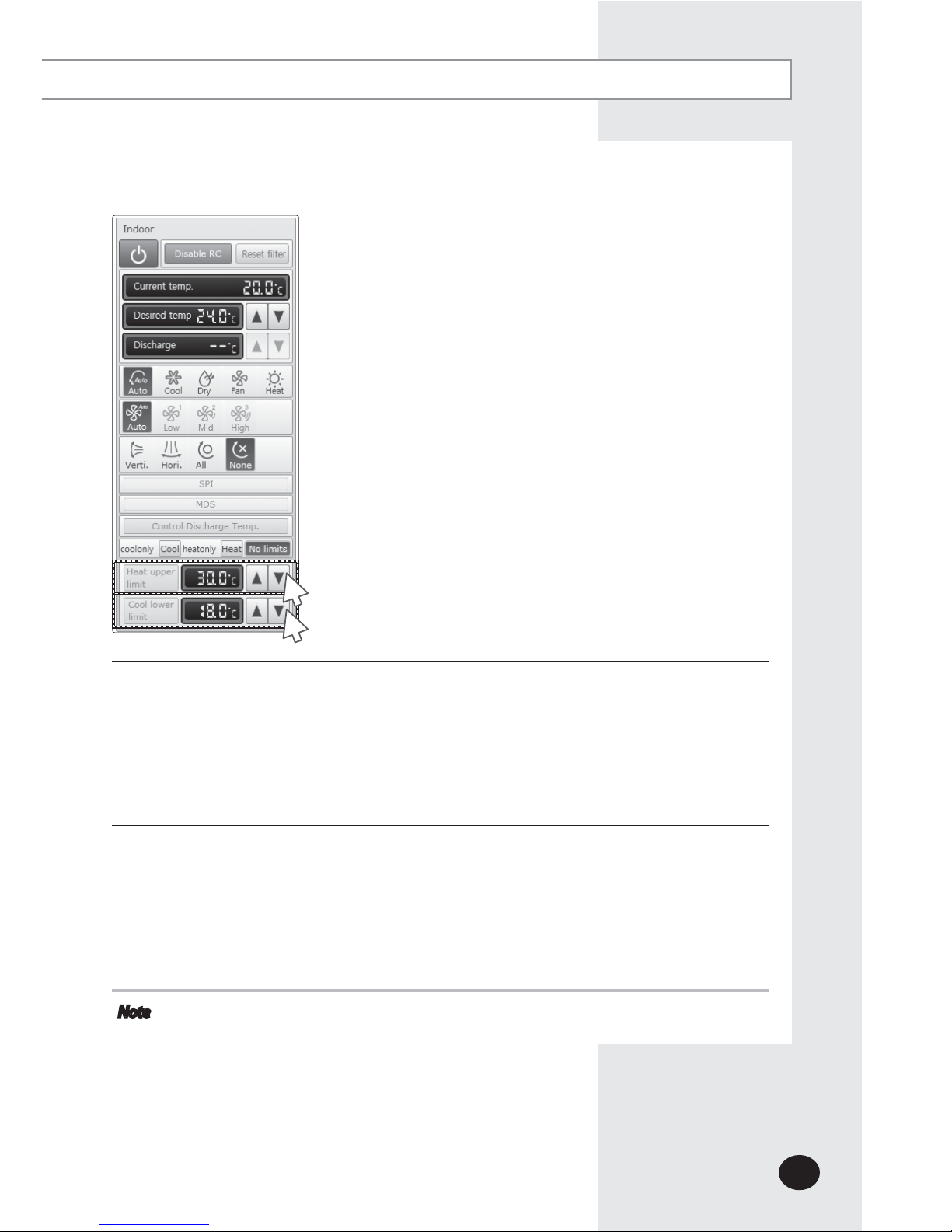
3
Set upper temperature limit by pressing [S] and [T].
X
Click 'Heat upper limit' to apply the upper temperature limit setting.
X Upper temperature limit can be set in the range of 16°C(61°F)~30°C(86°F).
X When an indoor unit is operating in Heat mode and the upper temperature limit is
applied, you cannot set the desired temperature higher than the upper temperature
limit.
4
Set lower temperature limit by pressing [S] and [T].
X
You can set lower temperature limit by clicking 'Cool lower limit'.
X Lower temperature limit can be set in the range of 18°C(64°F)~30°C(86°F).
X When indoor unit is operating in Cool or Dry mode and the low temperature limit is
applied, you cannot set the desired temperature lower than the lower temperature
limit.
Note
X You cannot set the lower and upper temperature limit of ERV, ERV PLUS, Freshduct,
DVM CHILLER.
3
4
E-30
Control and Monitoring (Continued)
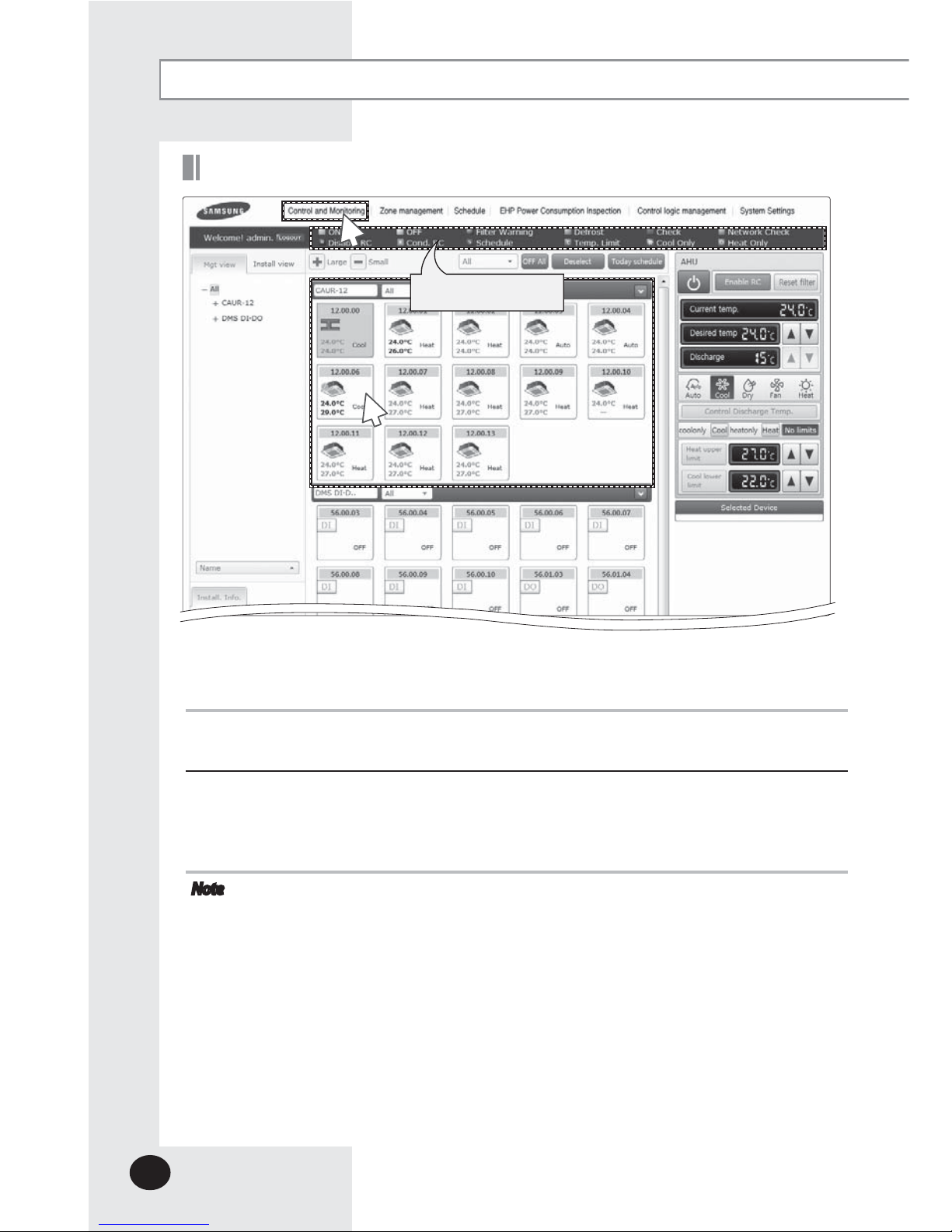
Monitoring AHU Operation Status
You can monitor the operation status of AHU, and control AHU as a whole,
or as individual units.
1
Click [Control and Monitoring] when DMS2.5 web page menu screen appears.
X [Control and Monitoring] screen will appear when you log-in to DMS2.5 web page.
2
Check current status of AHU.
X Check AHU status through status display window.
X When the selected AHU is switched on, the remote controller panel will be
automatically activated.
Note
X To control AHU, refer to the ‘Controlling an indoor unit’ steps.
(Refer to the page 20~23)
X AHU’s fan speed is fixed as high.
X You cannot set air flow direction of AHU.
X To set the operation mode limit of AHU, refer to the ‘Indoor unit operation mode
limit’ steps. (Refer to the page 24~25)
X T
o set the lower/upper temperature limit of AHU, refer to the ‘Setting lower/upper
temperature limit of indoor unit’ steps. (Refer to the page 26~27)
X To set the cooling/heating discharge temperature, refer to the step 11~12 of
'Controlling and indoor unit'. (Refer to the page 23)
X Cooling discharged temperature can be set in the range of 8 °C(46 °F)~25 °C(77 °F).
X Heating discharged temperature can be set in the range of 18 °C(64 °F)~43 °C(109 °F).
1
2
Status display window

E-31
Monitoring Fresh duct operation status
You can monitor the operation status of Fresh duct, and
control the Fresh duct as a whole, or as individual units.
1
Click [Control and Monitoring] when DMS2.5 web page
menu screen appear.
X [Control and Monitoring] screen will appear when you
log-in to DMS2.5 web page.
2
Check the current status of a Fresh duct.
X
Check the status of a Fresh duct through the status
display window.
X
When the selected Fresh duct is switched on, the
remote controller panel will be automatically activated.
1
2
Status display window

E-32
Control and Monitoring (Continued)
Controlling a Fresh duct
1
2
4
3
1
Click [Control and Monitoring] when DMS2.5 web page
menu screen appear.
X [Control and Monitoring] screen will appear when you
log-in to DMS web page.
2
Check the current status of a Fresh duct.
X Check the status of a Fresh duct through the status display
window.
X
When the selected Fresh duct is switched on, the remote
controller panel will be automatically activated.
3
Turn the Fresh duct on by clicking [ ].
X
Remote controller panel will be activated.
4
Set cooling/heating discharge temperature by clicking
[S]
and[T].
X
When the Fresh duct is in Cool mode, the Fresh duct can
be set as cooling discharge
temperature and when the Fresh duct is in Heat mode,
the Fresh duct can be set as heating discharge
temperature.
X
When the Fresh duct is in Auto or Fan mode, the discharge
temperature cannot be adjusted.

Note
X Refer to the ‘OnOff controller’ for Fresh duct control.
(Refer to page 22~25)
X The fan speed of a Fresh duct is fixed as ‘High’.
X Setting air flow direction of a Fresh duct is not
available.
X Refer to the ‘Indoor unit operation mode limit’ for
Fresh duct operation mode limit.
(Refer to page 26~27)
E-33

E-34
You can monitor the operation status of ERV, and control the
ERV as a whole, or as individual units.
1
Click [Control and Monitoring] when DMS2.5 web page
menu screen appears.
X
[Control and Monitoring] screen will appear when you
log-in to DMS2.5 web page.
2
Check current status of ERV.
X Check the status of ERV through the status display window.
X
When the selected ERV is switched on, the remote controller
panel will be automatically activated.
Monitoring ERV Operation Status
2
Status display window
1
Control and Monitoring (Continued)

E-35
Controlling ERV
You can monitor the operation status of ERV, and control the
ERV as a whole, or as individual units.
1
Click [Control and Monitoring] when DMS2.5 web page
menu screen appears.
X
[Control and Monitoring] screen will appear when you
log-in to DMS2.5 web page.
2
Select an ERV to control.
X
When the selected ERV is switched on, the remote controller
panel will be automatically activated.
3
Turn ERV on by pressing [ ].
X The remote controller panel will be activated.
1
3
2

E-36
4
6
5
4
Select the operation mode.
X
You can select Auto, HeatEx, By pass and Sleep.
5
Select the fan speed.
X
You can select Low, High and Turbo.
X Fan speed is set to Low in Sleep mode.
6
Set remote controller settings.
X You can select Enable RC, Disable RC, and Cond. RC.
X When selecting [Enable RC], indoor unit control by wired/
wireless remote controller is not possible. Indoor unit
control is only available in DMS2.5 web page.
X
Click [
] when you want to use wired remote controller in
each room.
Note
X When filter warning sign is displayed on ERV status
window
Select the ERV and click [Reset filter]. Filter warning will be
released.
X Make sure that ERV must be turned on to control.
X Selecting remote controller and filter reset are possible
even if the power of indoor unit is off.
Control and Monitoring (Continued)

E-37
Monitoring ERV PLUS operation status
You can monitor the operation status of ERV PLUS,
and control the ERV PLUS as a whole, or as individual units.
1
Click [Control and Monitoring] when DMS2.5 web page
menu screen appears.
X [Control and Monitoring] screen will appear when you
log-in to DMS2.5 web page.
2
Check the current status of ERV PLUS.
X Check the status of ERV PLUS through the status display
window.
X
When the selected ERV PLUS is switched on, the remote
controller panel will be automatically activated.
1
2
Status display window

Controlling ERV PLUS
1
Click [Control and Monitoring] when DMS2.5 web page menu screen appear.
X [Control and Monitoring] screen will appear when you log-in to DMS2.5 web page.
2
Select ERV PLUS to control.
X Check the status of ERV PLUS through the status display window.
X When the selected ERV PLUS is switched on, the remote controller panel will be
automatically activated.
3
Turn the ERV PLUS on by clicking [ ].
X
Remote controller panel will be activated.
4
Select the operation mode
X You can select Auto, Cool, Off and Heat mode.
Note
X Refer to the ‘Controlling ERV’ for ERV PLUS control. (Refer to page 35~36)
X Refer to the ‘Indoor unit operation mode limit’ for ERV PLUS operation
mode limit. (Refer to page 26~27)
1
2
3
E-38
4
Control and Monitoring (Continued)

E-39
Controlling Hydro unit
1
2
3
1
Click [Control and Monitoring] when DMS2.5 web page
menu screen appear.
X [Control and Monitoring] screen will appear when you
log-in to DMS2.5 web page.
2
Select a Hydro unit to control.
X When the selected Hydro unit is switched on, the remote
controller panel will be automatically activated.
X
Hydro unit does not support multiple selection with
other devices and you can only control and monitor the
Hydro unit individually. When you select Hydro unit while
multiple devices are already selected, previously selection
(of multiple devices) will be canceled.
3
Turn the Hydro unit on by clicking [ ].
X
Remote controller panel will be activated.

E-40
4
Icon will be activated when either Thermostat 1 or
Thermostat 2 is on.
5
Icon will be activated when the Outing mode is on.
6
Type of temperature control will be displayed. Control
and monitoring status of current temperature, desired
temperature, operation mode, Heat upper limit and Cool
lower limit will be changed depending on the type of
temperature control.
X Room: You can only control Cool and Heat mode.
X Water out: You cannot adjust the desired temperature in
Auto mode.
6
4
5
8
9
11
12
10
7
Control and Monitoring (Continued)

E-41
7
Select Heat upper limit and Cool lower limit by clicking [S] [T].
8
Select [coolonly] or [heatonly] button.
9
Click the button to turn on/off the power for direct heat
water.
X You can turn on the power for direct hot water only when
the operation mode is on Auto or Heat mode.
10
Select desired temperature for hot water by clicking [S] [T].
11
Select desired operation mode for hot water.
X Select the operation mode from Eco/Standard/Power.
12 Select DHW upper temperature limit by clicking
[S] [T].
Note
X Since the Hydro Unit and Hydro Unit HT does not
have any filters, filter monitoring and filter reset is
not available.

E-42
Controlling Hydro Unit HT
1
2
3
1
Click [Control and Monitoring] when DMS2.5 web page menu screen appear.
X [Control and Monitoring] screen will appear when you log-in to DMS2.5 web page.
2
Select a Hydro Unit HT to control.
X When the selected Hydro Unit HT is switched on, the remote controller panel will be
automatically activated.
X Hydro Unit HT does not support multiple selection with other devices and you can
only control and monitor the Hydro Unit HT individually. When you select Hydro
Unit HT while multiple devices are already selected, previously selection (of multiple
devices) will be canceled.
3
Turn the Hydro Unit HT on by clicking [ ].
X
Remote controller panel will be activated.
Control and Monitoring (Continued)

E-43
4
Icon will be activated when either Thermostat 1 or
Thermostat 2 is on.
5
Icon will be activated when the Outing mode is on.
6
Type of temperature control will be displayed. Control
and monitoring status of current temperature, desired
temperature, operation mode, Heat upper limit and Cool
lower limit will be changed depending on the type of
temperature control.
X Room: You can only control Heat mode.
X Water out: You can only control Auto and Heat mode.
You cannot adjust the desired temperature
in Auto mode.
6
4
5
8
7
9
11
12
10

E-44
7
Select Heat upper limit by clicking [S] [T].
8
To select exclusive operation mode, select [heatonly] or [No
limits].
9
Click the button to turn on/off the power for direct heat
water.
X You can turn on the power for direct hot water only when
the operation mode is on Auto or Heat mode.
10
Select desired temperature for hot water by clicking [S] [T].
11
Select desired operation mode for hot water.
X Select the operation mode from Eco/Standard/Power/
Force.
12 Select DHW upper temperature limit by clicking
[S] [T].
Note
X Since the Hydro Unit HT does not have any filters,
filter monitoring and filter reset is not available.
X Hydro Unit HT does not support temperature in
Fahrenheit.
Controlling Single EHS
1
Basic control operating procedures are the same as 'Hydro
Unit', and others are as follows:
X 'Force' is added to the hot water mode.
X The hot water thermostat is also considered when the
thermostat icon is activated.
Control and Monitoring (Continued)

E-45
Monitoring DMS DI/DO Operation Status
1
Click [Control and Monitoring] when DMS2.5 web page
menu screen appears.
X [Control and Monitoring] screen will appear when you
log-in to DMS2.5 web page.
2
Check the current status of DI and DO device.
3
Monitor the device through the control panel.
Note
X Entering OnOff becomes impossible for DI device.
X Entering OnOff becomes possible for DO device.
X Entering control value becomes impossible for
DI/DO device.
X You can control and monitor DI/DO which built-in
DMS2.5. However, DI 1, 2 and DO 1, 2, 9, 10 are
excluded
from controlling and monitoring because they are
used for the internal function of DMS.
1
3
2

E-46
Controlling DMS DO
1
Click [Control and Monitoring] when DMS2.5 web page menu screen appears.
X [Control and Monitoring] screen will appear when you log-in to DMS2.5 web page.
2
Select DO device to control when control and monitoring screen appears.
X Check the status of DI or DO device.
1
3
3
Turn DO device on by clicking [ON]/[OFF] button on the control panel.
Note
Remote controller setting is not possible for DI/DO device.
Control and Monitoring (Continued)
2

E-47
Controlling FCU Kit
1
Click [Control and Monitoring] when DMS2.5 web page menu screen appears.
X [Control and Monitoring] screen will appear when you log-in to DMS2.5 web page.
2
Select FCU to control when control and monitoring screen appears.
X Check the status of an indoor unit through status display window.
X When the selected indoor units are switched on, the remote controller panel will be
automatically activated.
3
Turn the selected indoor units on by clicking [ ].
X Remote controller panel will be activated.
1
3
2

E-48
Note
X Refer to the ‘Controlling an indoor units’ steps for FCU
Kit control. (Refer to page 22~25)
X
Refer to the ‘Indoor unit operation mode limit’ for FCU
Kit operation mode limit. (Refer to page 26~27)
X
Refer to ‘Setting Lower/Upper Temperature Limit of
an Indoor Unit’ for FCU Kit temperature limits.
(Refer to page
28~29
)
Control and Monitoring (Continued)

E-49
Controlling DVM CHILLER
1
Click [Control and Monitoring] when DMS2.5 web page menu screen appears.
X [Control and Monitoring] screen will appear when you log-in to DMS2.5 web page.
2
Select DVM CHILLER to control when control and monitoring screen appears.
X Check the status of an indoor unit through status display window.
X When the selected indoor units are switched on, the remote controller panel will be
automatically activated.
3
Turn the selected indoor units on by clicking [ ].
X Remote controller panel will be activated.
1
2
3

E-50
4
Select the operation mode.
X You can select Cool, Cool Storage, Heat, and Hot Water mode.
5
Select the operation pattern.
X You can select Standard, Rotation, Efficiency pattern.
6
Select Water Law setting.
X You can enable/disable button to select Water Law.
X You cannot adjust the desired temperature in Water Law.
7
Select Quiet function.
X You can enable/disable button to select Quiet function.
8
Select Forced Fan function.
X You can enable/disable button to select Forced Fan function.
9
Select Demand level by clicking [S] [T].
X You can select Demand level in range of 50%~100%.
Note X Power, desired temperature, operation mode, operation
pattern, Water Law, Quiet function, Forced Fan function,
Demand function can be controlled and monitored properly
when the options are installed on DVM CHILLER.
Control and Monitoring (Continued)
5
6
7
8
9
4

E-51
Monitoring the selected multiple devices operation status
2
You can monitor the operation status of other type devices,
and control other type devices as a whole, or as individual units.
1
Click [Control and Monitoring] when DMS2.5 web page menu screen appears.
X [Control and Monitoring] screen will appear when you log-in to DMS2.5 web page.
2
Check the status of the selected multiple devices.
X Check the status of an indoor unit through status display window.
X When the selected devices are switched on, the remote controller panel will be
automatically activated.
Note
X When users select multiple devices, 'Basic Control' will be displayed
on the screen. (This is when different types of multiple devices are selected.)
X The current status of last selected indoor unit type devices (Indoor unit, AHU,
Fresh duct) will be displayed on the 'Indoor control'.
X The status of last selected ERV type devices (ERV, ERV PLUS) will be displayed
on the 'Ventilation Control'.
X The list of the selected multiple devices will be displayed on the ‘Selected Device’.
X Hydro Unit, Hydro unit HT and Single EHS do not support multiple selection with
other devices and you can only control and monitor the Hydro Unit, Hydro Unit
HT and Single EHS individually. When you select Hydro Unit or Hydro Unit HT or
Single EHS while multiple devices are already selected, previously selection (of
multiple devices) will be canceled.
Status display window
1

E-52
Control and Monitoring (Continued)
Controlling the selected multiple devices
1
2
1
Click [Control and Monitoring] when DMS2.5 web page
menu screen appears.
X [Control and Monitoring] screen will appear when you
log-in to DMS2.5 web page.
2
Check the status of the selected devices.
X Check the status of an indoor unit through status display
window.
X
When the selected devices are switched on, the remote
controller panel will be automatically activated.
3
Turn the selected devices on by clicking [ ].
X Remote controller panel will be activated.
3

E-53
4
Select the desired temperature by clicking [S][T].
X Each time you press the buttons, the temperature will be adjusted by 1 or 0.1°C
(or by 1°F).
X
If Auto/Cool/Dry mode is in operation, you can adjust the desired temperature in the
range of 18°C(64°F)~30°C(86°F).
X
If Heat mode is in operation, you can adjust the desired temperature in the range of
16°C(61°F)~30°C(86°F).
X
You cannot adjust the desired temperature in Fan mode.
X When the operation mode of an indoor unit is in Cool or Dry mode, you cannot set
the desired temperature lower than lower limit temperature if lower limit is enabled.
X
When the operation mode of an indoor unit is in Heat mode, you cannot set the
desired temperature higher than upper limit temperature if upper limit is enabled.
5
Select the operation mode.
X
Y
ou can select Auto, Cool, Dry, Fan and Heat mode.
6
Select the fan speed.
X You can select Auto, Low, Mid and High.
X If Auto/Dry mode is in operation, fan speed will be set as Auto fan speed.
X If Fan mode is in operation, you cannot select Auto fan speed.
4
5
6
7
8
9

E-54
Control and Monitoring (Continued)
7
Select the ERV operation mode.
X You can select Auto, Heat Ex, By pass and Sleep mode.
8
Select the fan speed.
X You can select Low, high and Turbo.
X If Sleep mode is in operation, the fan speed will be set as
Low fan speed.
9
When controlling certain types of devices in detail, select
the device you want to control on the list of the ‘Selected
Device’.
Note
X If the ERV type devices are not on the list of the
‘Selected Device’, ventilation control will not be
activated.
X If the indoor unit type devices are not on the list of the
‘Selected Device’, Indoor control will not be activated.
X When controlling an indoor unit, ERV devices
(ERV, ERV PLUS) cannot be controlled.
X When controlling ERV devices, Indoor unit (Indoor unit,
AHU, Fresh duct) cannot be controlled.
X You can select power OnOff, Disable RC, Reset filter,
Indoor Control (Desired temp, operation mode, fan
speed) and ERV Control in the ‘Basic control’.
X Power OnOff, Disable RC and Reset filter are controlled
to all the devices.
X When selecting multiple devices, the list of the selected
devices will be displayed at the bottom of the remote
controller. When selecting the device you want to
control, the remote control panel of the selected device
will be activated and you can control the selected
device in detail. However, the rest of the devices cannot
be controlled other than the selected device.
X DVM CHILLER cannot be selected with other types of
devices and can be selected with DVM CHILLERs only.

E-55
Checking the Installation Information
You can check the installation status of currently connected
device.
1
Click [Control and Monitoring] when DMS2.5 web page
menu screen appears.
X
[Control and Monitoring] screen will appear when you
log-in to DMS2.5 web page.
2
Click ‘Install.Info’. tab at the bottom left of the screen.
3
Check installation status of currently connected device in the
installation information tab.
X
You can check installation information by pressing
[∧] and [∨] buttons.
1
3
2

E-56
View the Control History & Power Consumption
3
You can select a device and view control history and power
consumption information.
1
Click [Control and Monitoring] when DMS2.5 web page
menu screen appears.
X
[Control and Monitoring] screen will appear when you
log-in to DMS2.5 web page.
2
Select a device you want to view control history and power
consumption.
3
Click [View control history & power consumption]tab and
wait for a while.
X
Control history and power consumption information are
received from DMS2.5.
X ‘Data receiving’ message will appear on the bottom right
of the tab.
Control and Monitoring (Continued)
1
2

E-57
4
When data reception is completed from DMS2.5, check
control history and power consumption of selected device.
Note
X In ‘Control history’, you can check power control and
remote controller usage status.
X Operation mode, desired temperature, air flow and fan
speed control shows you the controlled time and type
of control only.
X If SIM/PIM is not installed, power consumption
information may not be correct.
X Power consumption information is displayed only
when SIM/PIM is installed.
X If SIM/PIM is removed, value measured with
SIM/PIM will be displayed.
4

E-58
Cycle Monitoring
You can select an indoor unit and check cycle information.
1
Click [Control and Monitoring] £ [Cycle Monitoring] when DMS2.5 web page menu
screen appears.
2
Click [Select].
X
DMS2.5 installation information will be displayed.
3
Select a device to check cycle information.
X
If you select OnOff controller, its subordinate outdoor unit which has the earliest
address will be selected.
X If you select an outdoor unit, all the information of the module (that are connected
to the selected outdoor unit) will be displayed.
X
If you select indoor unit, upper outdoor unit will be selected.
4
Cycle information of selected outdoor unit and subordinate indoor units.
X
If the status of outdoor unit and indoor unit is changed, status value turns into blue.
Control and Monitoring (Continued)
1
2
3

E-59
2
Indoor Unit Usage Restriction_Operation Limit
You can set the operation of indoor unit as cooling only and
heating only.
1
Click [Control and Monitoring] £ [Indoor unit usage
restriction] when DMS2.5 web page menu screen appears.
2
Press [Edit] button.
3
Set the limit mode.
X You can select 'Cool-only’, ‘Heat-only’ or ‘None’.
- For cooling only indoor unit, you can select cool, dry and
fan modes only.
- For heating only indoor unit, you can select heat and fan
modes only.
1
3

E-60
4
Set the control mode.
X
Control mode is used for DMS2.5 to set either 'cool only' or 'heat only' mode to
indoor and outdoor units.
Note
X Mixed operation can occur even if you set limit mode.
X If the indoor unit with operation mode limit is in mixed operation, DMS2.5 will
solve the problem automatically by controlling it in control mode.
X Since Hydro unit HT does not support Cool mode, control mode for Hydro unit HT
can only be set as 'Heat only' or 'None'.
Control and Monitoring (Continued)
X
When you set the operation mode limit, and if the outdoor unit is HP (Heat
pump) type, DMS2.5 will automatically change the operation mode limit setting
of all the indoor units connected to same outdoor unit.
X
If the indoor unit is cooling only model, you cannot set the operation mode limit
to 'heatonly'.
X
DVM CHILLER cannot set 'only' mode.
4

E-61
Indoor Unit Usage Restriction_Temperature Limit in Cool/Heat mode
You can set temperature lower/upper temperature limit in cool/heat mode.
1
Click [Control and Monitoring] £ [Indoor unit usage restriction] when DMS2.5 web
page menu screen appears.
2
Press [Edit] button.
3
Set the lower/upper temperature limit.
X
You can set lower/upper temperature limit by selecting 'Enable'/'Disable'.
X
ERV PLUS and Fresh duct cannot set the lower temperature limit in Cool mode or
upper temperature limit in Heat mode.
X For Hydro unit and Single EHS, if the temperature control is set as 'Room', you can
set the Lower temperature limit in Cool mode and Upper temperature limit in Heat
mode according to room temperature. If the temperature control of Hydro unit is
set as 'Water out', you can set the Lower temperature limit in Cool mode and Upper
temperature limit in Heat mode according to water out temperature.
X For Hydro unit HT, if the temperature control is set as 'Room', you can set the Upper
temperature limit in Heat mode according to room temperature. If the temperature
control of Hydro unit is set as 'Water out', you can set the Upper temperature limit in
Heat mode according to water out temperature.
X
DVM CHILLER cannot set the lower temperature limit in Cool mode or upper
temperature limit in Heat mode.
4
Click [Save].
X
Indoor unit usage restriction setting will be saved.
2
1
4
3

E-62
Control and Monitoring (Continued)
Checking the Trouble History
1
Click [Control and Monitoring] £ [Trouble history]
when DMS2.5 web page menu screen appears.
2
Check all the trouble history.
X
You can check address, device type, occur
rence time,
resolution time, code number and status.
3
You can check detailed information on trouble history by
selecting the item in the list.
Note
XDMS2.5 saves maximum 1024 trouble histories.
If the number of history exceeds 1024, DMS2.5 will
delete the oldest history first.
XIf the same code trouble is detected repeatedly in the
same device on the same day, trouble history will be
shown as 1 case. If it occurs more than 2 times,
‘Resolution time’ may change every time you check.
And the number of repetition will be displayed in
‘Status’ field.
1
3

E-63
1
Checking the Trouble History by Date
DMS2.5 saves maximum 1024 trouble histories. If the number
of history exceeds 1024, DMS2.5 will delete the oldest history
first.
1
Click [Control and Monitoring] £ [Trouble history]
when DMS2.5 web page menu screen appears.
2
Enter the time period you want to check.
X Enter year/month/day in order.
3
Click [Search].
X
You can check address, device type, occurrence time,
resolution time, code number and status in the entered
period.
4
You can check detailed information on trouble history by
selecting the item in the list.
2
4
3

E-64
Control and Monitoring (Continued)
1
Click [Control and Monitoring] £ [Trouble history]
when DMS2.5 web page menu screen appears.
2
Select trouble history you want to delete.
3
Click [Delete].
X
Click [OK] from the confirm window. Selected trouble
history will be deleted.
Deleting the Trouble History
1
2
3

E-65
Outdoor unit control
Control for Occupied/Vacant room
1
Click [Control and Monitoring] £ [Outdoor unit control] when DMS2.5 web page menu
screen appears.
2
Click [Edit] and select the desired setting for Electric current control option, Heating
capacity calibration and Cooling capacity calibration.
X Outdoor unit self-control: Outdoor unit controls the value itself.
X Manual: Outdoor will be controlled at value set by the user.
3
Click [Save] and the outdoor unit will be controlled at set value.
X If the value was set manually on DMS2.5, outdoor unit will always operate at set
value.
Note
XOutdoor unit control is supported on certain models only, and the 'Outdoor unit
control page' only appears on those supported models.
1
Click [Control and Monitoring] £ [Occupied/Vacant room control] when DMS2.5 web
page menu screen appears.
2
Click [Edit] and select the desired setting for Mode, Desired temperature, Fan speed
and Apply.
3
Click [Save] and the unoccupied room will be controlled at set value.
Note
X The ‘Occupied/Vacant room control page’ only appears on those supported
models.
X
will appear on the indoor unit icon on [Control and Monitoring] screen, if the
indoor unit is unoccupied.
1
3
2

E-66
You can check operation status of indoor unit which is
controlled by DMS2.5.
1
Click [Control and Monitoring] £ [Checking operation status]
when DMS2.5 web page menu screen appears.
2
Check the operation history.
X
You can check the device type, occurrence time, control
unit, control type, and controlled device address of indoor
unit which is controlled by DMS2.5 and subordinate
controller.
3
You can check operation status by entering date.
X
Enter year/month/day then click [Search]. You can check
control history that occurred on the entered date.
4
You can check detailed control history which is controlled by
the command by pressing control history in the list.
Note
DMS2.5 saves the information of operation history for 180
days. However, it varies depending on saving space of DMS2.5.
Checking the Operation Status
3
4
1
Control and Monitoring (Continued)

E-67
Zone Setting & Edit – Individual/Group Initialization
1
Click [Zone management] £ [Zone Setting & Edit] when DMS2.5 web page menu screen
appears.
X Same screen will be displayed even if you click [Zone management] only.
2
Initialize the indoor unit organization as individual by clicking [Individual].
X
Individual initialization reorganizes connected indoor unit based on installation address.
3
Initialize the indoor unit organization as group by clicking [Group].
X Group initialization reorganizes connected indoor unit based on RMC address.
X
After group initialization, indoor units are displayed as one device when
upper zone is selected in the [Control and Monitoring] screen.
X
When editing zone after group initialization, moving in group is only allowed.
X After group initialization, subordinate devices cannot be moved individually to
the other zone.
Note
X Only the user who has authorization to edit all zones can use zone initialization.
- To the user who has no authorization to use zone initialization and manage
structure, button will not be displayed.
X If the user does not have authorization to edit zone, [Individual], [Group] and
[Zone edit] will not be displayed.
1
3
2
Zone Management

E-68
Zone Setting & Edit – Setting the User Authorization
1
Click [Zone management] £ [Zone Setting & Edit] when DMS2.5 web page menu
screen appears.
X Same screen will be displayed even if you press [Zone management] only.
2
Set user authorization for each zone.
X If the user has no authorization for the zone, controlling and monitoring of the
zone is restricted.
X The user who is allowed to control and monitor zone has ‘5’ sign.
3
Click [Save] to save.
X The user of currently selected zone is selected in the screen.
X You should set the authorization for controlling and monitoring the zone when the
user is added.
X If you do not set the authorization for zone after adding a user, the zone will not be
displayed even if the user logged in.
X Setting the user authorization is valid only for the zone displayed on the screen. If you
select the other zone setting without clicking save button after changing the setting,
user authorization for previously selected zone will be gone.
X When initializing zone, all rights are given to all users.
1
2
3
Zone Management (Continued)

E-69
1
1
Click [Zone management] £ [Zone Setting & Edit] when
DMS2.5 web page menu screen appears.
X Same screen will be displayed even if you press
[Zone management] only.
2
Click [Zone Edit].
X Zone edit screen will be displayed.
Zone Setting & Edit – Zone Edit
2

E-70
4
5
6
7
8
3
Click [▼] to set viewing option of zone edit list.
X You can select from viewing by 'Name’, ‘Address’ and ‘Address & Name'.
4
Edit item you want.
Create in the
above
Create a new zone on top of the selected zone.
Create in the
below
Create a new zone under the selected zone.
Create the sub
zone
Create a zone one step lower than the user selected.
You cannot create a zone under 5 steps in zone edit.
Remove
Remove selected zone. If the selected zone includes device,
the device will move to the top step.
Move up Move up the selected zone or indoor unit.
Move down Move down the selected zone or indoor unit.
Move to upper
level
Move the selected zone or indoor unit to the upper level.
Rename
Rename the selected zone or indoor unit.
You can use maximum 16 letters.
Cut Cut to move the selected zone or indoor unit,
Paste Move the cut zone or indoor unit to the selected zone.
3
Zone Management (Continued)

E-71
5
Click [Remove disappeared] to remove all disappeared devices which were found
after tracking.
6
Change zone properties.
X You can select “General”, “AHU”, and “Group”.
7
Click [Apply].
X Edited zone structure will be applied.
8
To cancel the setting, click [Cancel].
Mode Property name Description Remarks
Individual
initialization
mode
General
䯼
Virtual group which is managed by
installation address, not by RMC
address
䯼
The user can create and delete zone.
-
Group
Not applicable.
( Only supported in group initialization
mode.)
Not applicable.
(
Only supported in group initialization
mode.)
AHU
䯼
Virtual group which manages AHU kit
in general zone.
䯼
The user can create and delete.
䯼
It will be displayed as single device in
the control and monitoring screen, and
it can be controlled as single device.
䯼
You cannot move subordinate device
to the other zone.
Group
initialization
mode
General
䯼
V
irtual group which is set and
managed by the user.
䯼
The user can create and delete.
-
Group
䯼
Virtual group which is managed by
installation address, not by RMC
address.
䯼
The user cannot create and delete.
DMS2.5 creates it automatically.
䯼
It is displayed like as one device in the
control and monitoring screen and can
be controlled.
䯼
You cannot move subordinate device
to the other zone.
AHU
䯼
Virtual group which manages AHU kit
in general zone.
䯼
The user can create and delete.
䯼
It is displayed like as one device in the
control and monitoring screen and can
be controlled.
䯼
You cannot move subordinate device
to the other zone.

E-72
1
2
You can set, edit, delete and use the schedules for air
conditioner control.
1
Click [Schedule] £ [Schedule setting] when DMS2.5 web
page menu screen appears.
2
Click [New] in the schedule setting screen.
Note
It is not available to provide the schedule information to
BMS system.
3
Enter the schedule name when the schedule setting screen
appears.
4
Select schedule period you want by clicking calendar.
X
If you select 'No limit' when setting end date, it means
there is no period and it displays Dec 31st, 9999.
To set the end date, remove the check of ‘No limit’ or select
calendar icon which is on the right side of date.
5
To set an exception date in the schedule period, click [Add]
and select date(month/day) you want.
X
Select an exception date on the calendar window.
Creating New schedule
4
5
3
Schedule

E-73
6
To cancel the added exception date, select the exception
date it(
5
) and click [Delete].
X
Maximum 365 exception dates can be saved.
6

E-74
7
Click [Add] to select a device to apply.
X
The list of all the connected devices will be displayed.
X You can register a schedule for DMS DO as well.
X
You cannot select DVM CHILLER and other devices
simultaneously.
8
To cancel the selected device, select (5) the device again
and click [Delete].
7
8
Schedule (Continued)

E-75
9
Click [∨] to select repeat schedule you want and set an event.
X
You can select 'Weekly', 'Everyday' and '1day'.
However, the starting and end date should be same when you select '1day'.
X Enter 4 digits for OnOff time setting.
Ex) 8:00 ¤ 0800, 9:30 ¤ 0930
X
Remote controller setting is as follows.
●
Enable RC: Controlling indoor unit using wired/wireless remote controller or
indoor unit panel in each room is possible.
●
Disable RC: Controlling indoor unit using wired/wireless remote controller or
indoor unit panel in each room is not possible.
●
Cond. RC
- ON by OnOff controller, DMS2.5: Controlling indoor unit using wired/wireless
remote controller or indoor unit panel in each
room is possible.
- OFF by OnOff controller, DMS2.5: Controlling indoor unit using wired/wireless
remote controller or indoor unit panel in each
room is not possible.
X
Click [Add] to add event.
X To delete event, select an event(5) and click [Delete].
X Maximum 70 events can be set per 1 schedule. In case of week schedule, 10 events per
1 day can be set.
X
If starting and end time of schedule event are repeated, only the schedule event
which is made earlier will be executed.
10
9

E-76
10
Click [Save].
X
Set schedule information is saved in DMS2.5.
X
Click [Cancel] to cancel schedule setting.
Note
X If you select dry mode among basic modes, auto fan
speed is only available.
X
When the operation mode is ‘Auto’, fan speed is always
set to ‘Auto’.
X
When the operation mode is ‘Fan’, you cannot control
fan speed as ‘Auto’.
X
When the operation mode is ‘Dry’, fan speed is always
set to ‘Auto’.
X
When you select sleep mode among ERV modes, ‘Mid’
fan speed is only available.
X
If the tracking is not completed, schedule setting is not
possible. To use proper schedule function, make sure to
complete tracking with installation engineer.
X
‘Off’ operation works only with ERV PLUS.
X '
Cool Storage' and 'Hot Water' mode works by
DVMCHILLER only.
X The Turbo fan speed is available only in the devices
that support the Turbo fan speed. For the devices that
do not support the Turbo fan speed, the Auto or High
fan speed operates, even though the Turbo fan speed is
selected.
Schedule (Continued)

E-77
1
Click [Schedule] £ [Schedule setting] when DMS2.5 web
page menu screen appears.
2
Click [New EHS] in the schedule setting screen.
3
Enter the schedule name when the schedule setting screen
appears.
4
Select schedule period you want by clicking calendar.
X
If you select 'No limit' when setting end date, it means
there is no period and it displays Dec 31st, 9999.
To set the end date, remove the check of ‘No limit’ or select
calendar icon which is on the right side of date.
5
To set an exception date in the schedule period, click [Add]
and select date(month/day) you want.
X
Select an exception date on the calendar window.
Creating new schedule for EHS
1
2
4
5
3

E-78
6
To cancel the added exception date, select the exception
date (
5
) and click [Delete].
X
Maximum 365 exception dates can be saved.
6
Schedule (Continued)

E-79
7
Click [Add] to select a device to apply.
X
The list of all the connected devices will be displayed.
Select a device and click [OK].
X You can only select one device.
8
To cancel the selected device, select (5) the device again
and click [Delete].
7
8

E-80
9
Click [∨] to select repeat schedule you want and set an event.
X
You can select 'Weekly', 'Everyday' and '1day'. However, the starting and end date
should be same when you select '1day'.
X Enter 4 digits to set the time for turning ON/OFF the EHS and the Hot water.
Ex) 8:00 ¤ 0800, 9:30 ¤ 0930
X
Remote controller setting is as follows.
●
Enable RC: Controlling indoor unit using wired/wireless remote controller or
indoor unit panel in each room is possible.
●
Disable RC: Controlling indoor unit using wired/wireless remote controller or
indoor unit panel in each room is not possible.
●
Cond. RC
- ON by OnOff controller, DMS2.5: Controlling indoor unit using wired/wireless
remote controller or indoor unit panel in
each room is possible.
- OFF by OnOff controller, DMS2.5: Controlling indoor unit using wired/wireless
remote controller or indoor unit panel in
each room is not possible.
X
Click [Add] to add event.
X To delete event, select an event(5) and click [Delete].
X Maximum 70 events can be set per 1 schedule. In case of week schedule and 10 events
per 1 day can be set.
X
If starting and end time of schedule event are repeated, only the schedule event
which is made earlier will be executed.
10
9
Schedule (Continued)

E-81
10
Click [Save].
X
Created schedule information will be saved in DMS2.5.
X
Click [Cancel] to cancel schedule setting.
Note
X Since Hydro unit HT does not support Cool mode, you
should not add any schedules related to Cool mode.
X If the desired temperature is set when the operation
mode is ‘None’, when the actual schedule should start
working, it may not work at desired temperature
setting depending on control type and mode.
X Do not input the desired temperature when the
operation mode is set to 'Auto'.
X Do not turn on the power for direct hot water when the
operation mode is set to 'Cool'.
X Schedule setting is not available when the tracking is
not completed. To use the schedule function normally,
complete the tracking with the installation expert.
X When Thermostat #1 or Thermostat #2 is ON, the
desired temperature and operation mode cannot be
controlled.
X W
hen the hot water thermostat is ON, the schedule of
the hot water temperature cannot be controlled.

E-82
Editing Schedule
1
Click [Schedule] £ [Schedule setting] when DMS2.5 web page menu screen appears.
2
Select the schedule to edit.
X
For the currently operating schedule, you can only check it.
3
Click [Edit].
X
Edit schedule when the schedule edit screen appears.
X
Editing schedule method is same as “Creating New Schedule”. (Refer to page
72~76)
1
2
3
Schedule (Continued)

E-83
Deleting Schedule
1
Click [Schedule] £ [Schedule setting] when DMS2.5 web page menu screen appears.
2
Select the schedule to delete.
3
Click [Delete].
X
Click [OK] in confirm window and selected schedule will be deleted.
X
Deleting schedule is possible only when the schedule is in stop status. If you want to
delete schedule which is currently applied, stop applying the schedule first.
1
3
2
Applying schedule
1
Click [Schedule] £ [Schedule setting] when DMS2.5 web page menu screen appears.
2
Select the schedule you want to use.
3
Use schedule functions by clicking [Run] and [Stop].
X To apply the selected schedule, click [Run].
X To stop the selected schedule, click [Stop].
Note
To stop all schedules, click [Stop all].
- Currently applied schedule will be stopped.
2
3
1

E-84
Checking Schedule Control History
1
Click [Schedule] £ [Checking schedule control history] when
DMS2.5 web page menu screen appears.
2
Select a date to check and then click [Search].
X
Only executed schedules can be searched.
3
You can check detailed setting by clicking the schedule
name.
Note
DMS2.5 saves the information or schedule control history
for 180 days.
However, it varies depending on saving space of DMS2.5.
2
3
Schedule (Continued)

E-85
Checking Inspection Result (with SIM/PIM)
You can check the operation history and power consumption saved in DMS for each
indoor unit.
1
Click [EHP Power Consumption Inspection] £ [Check inspection result] when DMS2.5
web page menu screen appears.
2
Set date and search condition (power consumption/proportion/individual indoor unit by
date) when inspection result screen appears.
X
Select year/month/day in order.
X Based on DMS2.5 time, you can check up to 365 days of watt-hour meter value.
3
Click [Search].
X
Inspection result will be displayed depending on set period and searching condition.
X
You can check power consumption only when watt-hour meter is connected.
If watt-hour meter is not connected, you can check operating proportion by indoor
unit only .
4
Click [Save as Excel].
X Searched inspection result will be saved as MS Excel file.
Note
XFor data management, it is recommended to save indoor unit inspection result
periodically.
XPower consumption inspection result is for reference only and should not be used
for official financial transactions.
4
1
2
3
EHP Power Consumption Inspection

E-86
Checking Inspection Result (without SIM/PIM)
1
Click [EHP Power Consumption Inspection] £ [Check
inspection result] when DMS2.5 web page menu screen
appears.
X Channel setting by indoor unit must be done in advance.
2
Set date when inspection result screen appears.
X
Select year/month/day in order.
X
Based on DMS2.5 time, You can check up to 365 days of
inspection results.
3
Enter power consumption value during the period.
X Virtual channel is value which is set in channel setting by
indoor unit.
4
Click [Calculate].
X
Power consumption by indoor unit during the period will
be displayed.
1
3
4
2
EHP Power Consumption Inspection (Continued)

E-87
5
Check the power consumption result of the selected period.
X Due to rounding the actual values, actual input value and
result value may different t
o each other.
X If you want to save the consumption result for selected
period as MS Excel file, click [Save as Excel].
X Click [Calculate] to go back to inspection result screen.
Note
XFor data management, it is recommended to save
indoor unit inspection result periodically.
XPower consumption inspection result is for reference
only and should not be used for official financial
transactions.

E-88
Setting the Inspection Section
1
Click [EHP Power Consumption Inspection] £ [Setting the
inspection section] when DMS2.5 web page menu screen
appears.
2
Click [Edit] when inspection result screen appears.
X
1 section is set as default.
3
Select a section and enter time by section.
X
You should enter time of section B when selecting 2
sections and enter time of section B and section C when
selecting 3 sections and enter time of section B, section C,
and section D when selecting 4 sections.
X
Correct format of time is HH:MM.
Ex) 4:30 in the afternoon
£
16:30
4
Click [Save].
X
Set power section will be saved in DMS2.5.
X
If you do not click [Save], changed setting will not be
saved.
Note
X Ex) When selecting 2 sections (A, B, A)
If the border time between A and B is 08:00 and 18:00,
section A is 00:00 ~ 08:00, section B is 08:01 ~ 18:00,
and second section A again is 18:01 ~ 24:00.
1
3
4
2
EHP Power Consumption Inspection (Continued)

E-89
Setting and Checking the meter
1
Click [EHP Power Consumption Inspection] £ [Setting and checking the meter] when
DMS2.5 web page menu screen appears.
X Setting watt-hour meter is possible only when SIM/PIM is installed.
2
Click [Edit] when the Setting and checking the meter screen appears.
X
CT proportion ‘1’ is set as default.
3
Set name and CT proportion of watt-hour meter.
X
You can use maximum 16 letters.
X
The range of CT proportion value is positive number from 1 to 5000.
X
CT proportion setting is required only when the meter type is 'electricity'.
4
Click [Save].
X
Set the meter information will be saved in DMS2.5.
X If you do not click [Save], changed setting will not be saved.
X
Watt-hour meter value shows actual value of currently connected watt-hour meter.
Watt-hour meter value will be updated automatically.
When using CT watt-hour meter, be careful that there can be difference with actual
power consumption as much as CT ratio error.
1
4
2
3

E-90
The meter history
1
Click [EHP Power Consumption Inspection] £ [Setting and checking the meter] when
DMS2.5 web page menu screen appears.
2
Click [The meter history] when the setting and checking the meter screen appears.
3
Select SIM/PIM address and date you want when the meter history screen appears.
X Enter year/month/day in order.
X
Based on DMS2.5 time, you can check up to 365 days of meter value history.
4
Click [Search].
X Meter value history of set period will be displayed.
5
Click [Excel].
X When you click the [Excel] button, meter value of all SIM/PIM throughout
the selected dates will be saved as MS Excel file.
2
1
3
4
5
For PIM, channel status should be set as "Enable" in order to
save the meter history in Excel file. (Refer to page 159~160)
EHP Power Consumption Inspection (Continued)

E-91
Setting and Checking Virtual Channel
1
Click [EHP Power Consumption Inspection] £ [Setting and
checking virtual channel] when DMS2.5 web page menu
screen appears.
X Maximum 128 virtual channels can be set.
Virtual channel is written in (24 ~ 31).(1 ~ 16) format
address.
Ex) 24.1, 25.2, 31.8
2
Click [Edit] when the setting and checking virtual channel
screen appears.
3
Set the name of virtual channel.
X
You can use maximum 16 letters.
4
Click [Save].
X
Set virtual channel name will be saved in DMS2.5.
X If you do not click [Save], changed setting will not be
saved.
3
1
4
2

E-92
Channel Setting by Indoor Unit
1
Click [EHP Power Consumption Inspection] £ [Channel
setting by indoor unit] when DMS2.5 web page menu screen
appears.
2
Click [Edit] when the setting channel by indoor unit screen
appears.
2
1
Some functions available on DMS2.5 web page may not be
functional at BACnet Gateway and LonWorks Gateway.
For detailed function, refer to the installation manual or
contact Samsung Electronics.
EHP Power Consumption Inspection (Continued)

E-93
3
Check the address and channel information of SIM/PIM which is connected to watt-
hour meter.
X
If 0~7 SIM/PIM units execute tracking, it will be displayed as 16~23 in DMS2.5.
4
Check the information of indoor/outdoor unit which is connected to
watt-hour meter.
5
Check the SIM/PIM channel(watt-hour meter) information of indoor/outdoor unit.
X You can set the channel when SIM/PIM is installed in DMS2.5.
X When bringing indoor unit’s power from outdoor unit, set the ‘Outdoor unit SIM
channel’ information only.
(
‘Outdoor unit SIM channel’ is referring to watt-hour meter which is connected to
outdoor unit.)
X When bringing indoor unit’s power from the other device, not from outdoor unit,
set the ‘Outdoor unit SIM channel’ and ‘Indoor unit SIM channel’ information.
(‘Indoor unit SIM channel’ is referring to watt-hour meter which is connected to
indoor unit.)
X
Power distribution will be executed automatically. The user does not need to check
the value of watt-hour meter.
X The maximum number of SIM channels for an outdoor unit is 4.
7
8

E-94
6
Check the virtual channel information of indoor/outdoor unit.
X
To execute power distribution without SIM/PIM, you should set virtual channel.
X When bringing indoor unit’s power from outdoor unit, set the ‘Outdoor unit virtual
channel’ information only.
(
‘Outdoor unit virtual channel’ is referring to watt-hour meter which is connected to
outdoor unit.)
X When bringing indoor unit’s power from the other device, not from outdoor unit,
set the ‘Outdoor unit virtual channel’ and ‘Indoor unit virtual channel’ information.
(‘Indoor unit virtual channel’ is referring to watt-hour meter which is connected to
indoor unit.)
X
The number of virtual channel varies depending on the number of outdoor unit
X To execute power distribution, you need to check watt-hour meter value manually.
X
Power distribution using SIM/PIM is more accurate than using indoor/outdoor unit
virtual channel. Therefore, it is recommended to execute power distribution using
SIM/PIM.
7
Set indoor unit to execute power distribution.
X
If you do not set the watt-hour meter information, the power distribution result of
the indoor unit will be displayed as ‘0’.
8
Click [Save].
X
Set channel information will be saved in DMS2.5.
X If you do not click [Save], changed setting will not be saved.
X Information of watt-hour meter connected to indoor/outdoor unit should be accurate.
If the watt-hour meter information is not accurate when you set channel information of
indoor unit, error may occur in the power distribution result.
X
You should set SIM/PIM channel information in the indoor unit if you want to execute
power distribution using SIM/PIM. If not, it means that you do not execute power
distribution. In this case, the power distribution result of the indoor unit will be ‘0’.
X If the information of watt-hour meter connected to indoor/outdoor unit is changed,
consult with installation engineer.
X DMS2.5 executes power distribution based on set information.
X Virtual channel is not available when you use BACnet or LonWorks Gateway function.
X DVM CHILLER and FCU Kit are excluded for power distribution devices.
EHP Power Consumption Inspection (Continued)

E-95
Checking Indoor Unit Operation Time
1
Click [EHP Power Consumption Inspection] £ [Checking
indoor unit operation time] when DMS2.5 web page menu
screen appears.
2
Select search condition (All indoor units by period/Individual
indoor unit by date) when Checking indoor unit operating
time screen appears.
X
Select year/month/day in order.
X
Based on DMS2.5 time, you can check up to 365 days of
operation time.
3
Click [Search].
X
Operation time will be displayed depending on set period
and condition.
4
Click [Save as Excel].
X
Searched operation time result will be saved as MS Excel
file.
Note
For data management, it is recommended to save indoor
unit operation time result periodically.
4
3
2
1

E-96
■
Control logic is used in the following situations.
Ex) The current temperature of the lab is higher than 29°C and you want cooling operation,
The current temperature of the office is lower than 10°C and you want heating operation
■
Period, day and time are included in specific conditions.
Setting Control Logic
You can set, edit, delete and use control logic for controlling device which is
connected to DMS2.5.
1
Click [Control logic management] £ [Setting control logic] when DMS2.5 web page
menu screen appears.
X Apply: Indicates control logic usage status.
X
Run: Indicates If the control logic is applied and whether the operation conditions
are met.
Ex)
If there is logic which says ‘If the current temperature of indoor unit is higher
than 29°C, control indoor unit as cool mode.’, 'Yes' will be displayed when the
indoor unit's current temperature is higher than 29°C. 'No' will be displayed
when the indoor unit's current temperature is lower than 29°C.
2
Click [New] when setting control logic screen appears.
X
Setting screen is composed of 4 categories.
- Name & time: Set the name and time(period, days, time) to apply of control logic.
- Factor edit: You can edit factor selection which is components of input/output.
- Input: Set the condition which makes control logic perform.
- Output: Set items to be controlled when the conditions of input are met.
Note
XIf different value is set for same control item of same address’ device, the indoor
unit follows the first control logic set among running control logics.
XIt is not available to provide the control logic management information to BMS
system.
1
2
Control Logic Management

E-97
3
Enter control logic name in the name field when the new
control logic setting screen appears.
X
You can use maximum 16 letters.
4
Set period, day and time in control logic screen.
X
Select year/month/day in order.
X Select a day to run during the control period.
X Control logic will be applied only when period, day and
time are united.
X If you select ‘Daily’ in day selection, control logic will run
regardless of day.
3
4

E-98
6
5
5
Select a factor in the input list.
X
Factor means the target to be controlled or standard item of logic decision.
6
Select the type of factor.
X
Single: It means 1 device.
Ex) Desired temperature of indoor unit
X
Arithmetic: It means 2 devices are connected by arithmetic operator.
Ex) Desired temperature of indoor unit 1 – Desired temperature of indoor unit 2
X
Function: It means several devices are using as value of function.
Ex)
Average(Current temperature of Indoor unit 1, Current temperature of
Indoor unit 2, Current temperature of Indoor unit 3)
Control Logic Management (Continued)

E-99
7
Click ‘Select’.
X
List of device which you can select will be displayed.
8
Select the device to use as factor.
X
Control and monitoring items will be displayed depending on selected device.
X
Control and monitoring items are as follows.
8
7
Type Item Value Remarks
Outdoor
unit
Current electric control
option
50%, 55%, 60%, 65%, 70%, 75%,
80%, 85%, 90%, 95%, 100%
Control impossible
Current heating capacity
calibration
25kg/cm², 26kg/cm², 27kg/cm²,
28kg/cm², 29kg/cm², 30kg/cm²,
31kg/cm², 32kg/cm², 33kg/cm²
Control impossible
Current cooling capacity
calibration
5~7°C(41~45°F), 7~9°C(45~48°F),
9~11°C(48~52°F), 10~12°C(50~54°F),
11~13°C(52~55°F),
12~14°C(54~57°F), 13~15°C(55~59°F)
Control impossible
Electric control option
50%, 55%, 60%, 65%, 70%, 75%,
80%, 85%, 90%, 95%, 100%
Heating capacity
calibration
25kg/cm², 26kg/cm², 27kg/cm²,
28kg/cm², 29kg/cm², 30kg/cm²,
31kg/cm², 32kg/cm², 33kg/cm²
Cooling capacity
calibration
5~7°C(41~45°F), 7~9°C(45~48°F),
9~11°C(48~52°F), 10~12°C(50~54°F),
11~13°C(52~55°F),
12~14°C(54~57°F), 13~15°C(55~59°F)
Error detection True, False
Control impossible
Limit operation mode None, Cool only, Heat only
-
Indoor unit
Power On, O
-
Current temp. Number
Control impossible
Desired temp. Number
-
Outdoor temp. Number
Control impossible
Operation mode Auto, Cool, Dry, Fan, Heat
-
Fan speed Auto, Low, Mid, High
Turbo is available
when the device
supports the Turbo
fan speed.
Air direction Vertical, Horizontal, All, None
-
RC usage Enable RC, Disable RC, Cond. RC
-
Error detection True, False
Control impossible
Limit operation mode None, Cool only, Heat only
-
ERV
Power On, O
-
Operation mode Auto, HeatEx, Bypass, Sleep
-
Fan speed Low, High, Turbo
-
RC usage Enable RC, Disable RC, Cond. RC
-
Error detection True, False
Control impossible
Limit operation mode None, Cool only, Heat only
-
ERV
PLUS
Power On, O
-
Outdoor temp. Number
Control impossible
ERV mode Auto, HeatEX, Bypass, Sleep
-
ERV fan speed Low, High, Turbo
-
Operation mode Auto, Cool, Heat, O
-
RC usage Enable RC, Disable RC, Cond. RC
-
Error detection True, False
Control impossible
Limit operation mode None, Cool only, Heat only
-
Type Item Value Remarks
Fresh
duct
Power On, O
-
Operation mode Auto, Cool, Fan, Heat
-
OA intake temp. Number
Control impossible
Outdoor temperature Number
Control impossible
Cool discharge temp. Number
-
Heat discharge temp Number
-
RC usage Enable RC, Disable RC, Cond. RC
-
Power On, O
-
Error detection True, False
Control impossible
Limit operation mode None, Cool only, Heat only
-
AHU
Current temp. Number
Control impossible
Desired temp. Number
-
Outdoor temp. Number
Control impossible
Operation mode Auto, Cool, Dry, Fan, Heat
-
RC usage Enable RC, Disable RC, Cond. RC
-
Power On, O
-
Error detection True, False
Control impossible
Limit operation mode None, Cool only, Heat only
-
DI
Status On, O
Control impossible
Error detection True, False
Control impossible
Limit operation mode None, Cool only, Heat only
-
DO
Status On, O
-
Error detection True, False
Control impossible
Limit operation mode None, Cool only, Heat only
-
Hydro Uni t,
Hydro Unit
HT, Single
EHS
Status On, O
Control impossible
Status On, O
-
Power On, O
-
Current temp. Number
Control impossible
Desired temp. Number
-
Current water out temp. Number
Control impossible
Desired water out temp. Number
-
Outdoor temp. Number
Control impossible
Operation mode Auto, Cool, Heat
Hydro unit HT cannot set Cool mode
DHW power On, O
-
Current DHW temp. Number
Control impossible
Desired water out temp. Number
-
DHW mode Eco, Standard, Power, Force
'Force' is only for
Single EHS
RC usage Enable RC, Disable RC, Cond. RC
-
Error detection True, False
Control impossible
Limit operation mode None, Cool only, Heat only
-

E-100
9
Select detailed item of factor.
X
Detailed item may be different depending on the type of selected device.
10
Click [Apply].
X
If you do not click [Apply], changed setting will not be saved.
11
Select comparison operator.
X
Types of comparison operators: = , =< , => , < , >, ≠
X
Comparison operator compares factor to standard factor.
11
10
9
Type Item Value Remarks
DVM
CHILLER
Power On, Off
-
Curre nt temp. Number
Control impossible
Desired temp. Number
-
Outdoor temp. Number
Control impossible
Operation mode Cool, Cool Storage, Heat, Hot Water
-
RC usage Enable RC, Disable RC, Cond. RC
-
Error detection True, False
Control impossible
Type Item Value Remarks
FCU Kit
Power On, Off
-
Curre nt temp. Number
Control impossible
Desired temp. Number
-
Operation mode Auto, Cool, Fan, Heat
-
Fan speed Auto, Low, Mid, High
-
RC usage Enable RC, Disable RC, Cond. RC
-
Error detection True, False
Control impossible
Limit operation mode None, Cool only, Heat only
-
Control Logic Management (Continued)
 Loading...