

Page 1

Data Management Server2
MIM-D00A
BACnet Gateway
MIM-B17
LonWorks Gateway
MIM-B18
Air Conditioner
user manual
DB98-32140A(3)
E
imagine the possibilities
Thank you for purchasing this Samsung product.
Page 2
E-2
Safety Precautions
• Before using the DMS2, read carefully these instructions.
• After reading the instructions, keep this user's manual in a handy and safe place.
If a user is changed, you must hand over the manuals.
• Never attempt to install the air conditioning system or to move the DMS2 by yourself.
WARNING
CAUTION
Do not attempt to install or repair this DMS2 by yourself.
This DMS2 contains no user-serviceable parts.
Always consult authorized service personnel for repairs.
When moving, consult authorized service personnel for
disconnection and installation of the DMS2.
Ensure that the wall is strong enough to support the
weight of the DMS2.
Must install the DMS2 with rated power supply.
In the event of a malfunction (burning smell, etc.),
immediately stop operation, turn off the electrical
breaker, and consult authorized service personnel.
Do not use inflammable gases near the DMS2.
Do not spill water into the DMS2.
Do not operate the DMS2 with wet hands.
Do not install the DMS2 in a location where it will come
into contact with the combustible gases, machine oil,
sulphide gas, etc.
Do not press buttons with a pointed thing.
Do not pull or bend the DMS2 cable excessively.
Do not use this DMS2 for other purpose.
Do not spray an insecticide or other combustible things
on the DMS2.
Do not clean the DMS2 with benzene, solvents or other
chemicals.
Do not give a shock to the DMS2 or disassemble it by
yourself.
Page 3

E-3
Contents
GENERAL DESCRIPTION ...................................................... 4
VIEWING THE PARTS .......................................................... 6
BEFORE USE ..................................................................... 8
MAIN FUNCTION ............................................................. 10
STARTING DMS2 ........................................................... 14
CONTROL AND MONITORING ............................................. 18
ZONE MANAGEMENT ....................................................... 45
SCHEDULE ..................................................................... 50
EHP POWER CONSUMPTION INSPECTION ............................ 60
CONTROL LOGIC MANAGEMENT ........................................ 71
SYSTEM SETTINGS ........................................................... 84
PIM SETTING ............................................................... 131
CHECK BEFORE USING PANEL .......................................... 133
SETTING NETWORK INFORMATION ................................... 134
CHECKING INDOOR/OUTDOOR UNIT INFORMATION ............ 136
CHECKING DMS2 VERSION ............................................ 137
DATA BACKUP SETTING ................................................. 140
CHECKING ERROR INFORMATION ..................................... 142
RESET PASSWORD ......................................................... 143
BUTTON LOCK .............................................................. 144
SAFETY HALT ............................................................... 145
TROUBLESHOOTING ....................................................... 146
SPECIFICATIONS ............................................................ 148
LICENSE ....................................................................... 149
Page 4
E-4
General Description
Introduction of DMS2 (Data Management Server2)
The DMS2 is an Internet based device for central management of Samsung system
air-conditioners. It supports LAN & WAN and operates 24 hours without a separate PC.
Advantages of DMS2 System
The DMS2 provides the following advantages:
Everyday Device–The DMS2 is operational all year long 24 hours.
Independent Operation–The DMS2 can operate schedule control, peak power control,
and power distribution without a PC.
Note In order to run peak power control and power distribution, relevant controllers
Internet Control
Web – The DMS2 has a built-in web server function and can be accessed from a
Using an Upper Level Controller–When a separate upper level controller (S-NET
Data Storage–The DMS2 has its own database built-in, therefore, trouble history,
Large Scale Management–At most 256 indoor units can be connected to one DMS2
Automatic ”e-mail” sending–When an error is occurred, inform the error details to an
need to be installed.
remote location to operate status
monitoring, control, trouble history, and schedule setting of the system
air-conditioners.
series) is used, a number of DMS2 can be controlled with one central management
system.
indoor unit installation information, and power distribution data can be saved and
retrieved.
and therefore, only one DMS2 can manage small and medium size buildings.
e-mail saved on DMS2.
Page 5
E-5
Terms
DMS2: The abbreviation of Data Management Server2.
Upper Controller: It means S-NET Series, a local controller of the DVM system.
Centralized Controller: A device that controls 16 groups of the DVM air conditioner.
Interface module: A data interface module of a DVM system which is located between
AHU(Air Handling Unit): Excutes heat exchange between air and cooling unit using
ERV(Energy Recovery Ventilator): Ventilating system using heat recover y function.
S-NET 3, S-NET mini and RMS are linked to a DMS2.
A central control device of a DVM system which is located
between a DMS2 and an outdoor unit interface module.
a central controller and an outdoor unit.
central air conditioning duct method.
Page 6
E-6
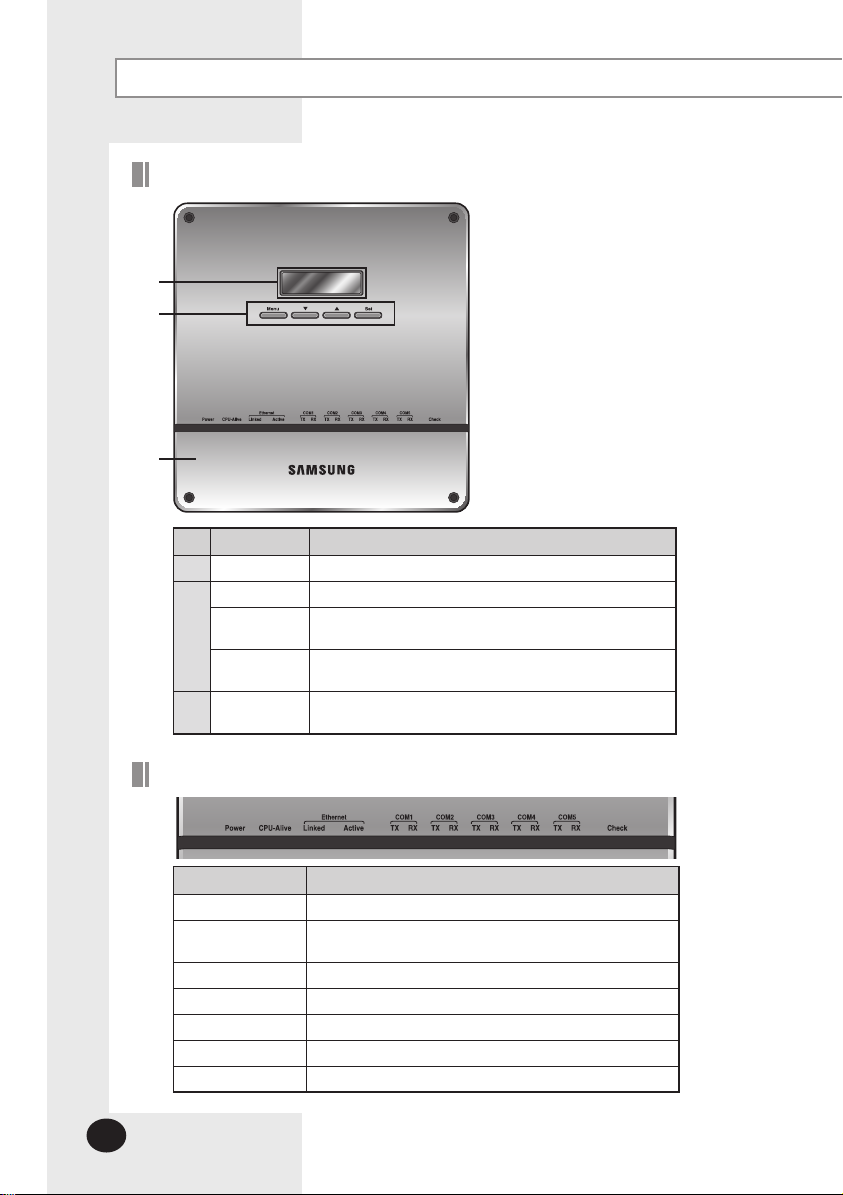
Viewing the Parts
Front View
No. Name Description
LCD Display Display current time/ Check menu
Menu button Access to main menu
▼/▲ button
Set button
Bottom cover
Select the function you want and set detailed functions in
main menu
Check the function you want from main menu
and select it
Unfasten 2 screws on the bottom and separate the bottom
cover from DMS2. Then check cable connection part.
Indicator
Name Description
Power Turns blue when the power is supplied.
CPU Alive
Ethernet–Linked Turns green during normal connection.
Ethernet–Active Blinks in orange during normal transmission/reception.
COM1~5 – TX Blinks in green during normal transmission.
COM1~5 – RX Blinks in green during normal reception.
Check Turns green when notice occurs.
Blinks in orange with 1 second intervals during normal
operation.
Page 7
E-7
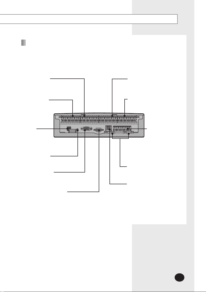
Bottom View
Separate bottom cover by unfastening 2 screws on the bottom.
DI Terminal2
Connect Digital Input
- Channel 6~Channel10
DI Terminal1
Connect Digital Input
- Channel 1~Channel 5
Power
Terminal
Connect
DMS2 adapter
Reset Button
Reset DMS2
Serial Terminal
Service agent checks error
status
SD Card Socket
Socket for sub memory (SD or MMC)
( Sub memory is for DMS2 program update and set
information saving)
※ Purchase SD card separately.
DO Terminal1
Connect Digital Output
- Channel 1~Channel 5
DO Terminal 2
Connect Digital Output
- Channel 6~Channel 10
RS485
Communication
terminal
Connect for RS485
communication
with devices such as
centralized controller/
interface module
- COM1 ~ COM5
Cable tie groove
Arrange cables connected to
DMS2
LAN Terminal
Connect LAN cable
Page 8
E-8
Before Use
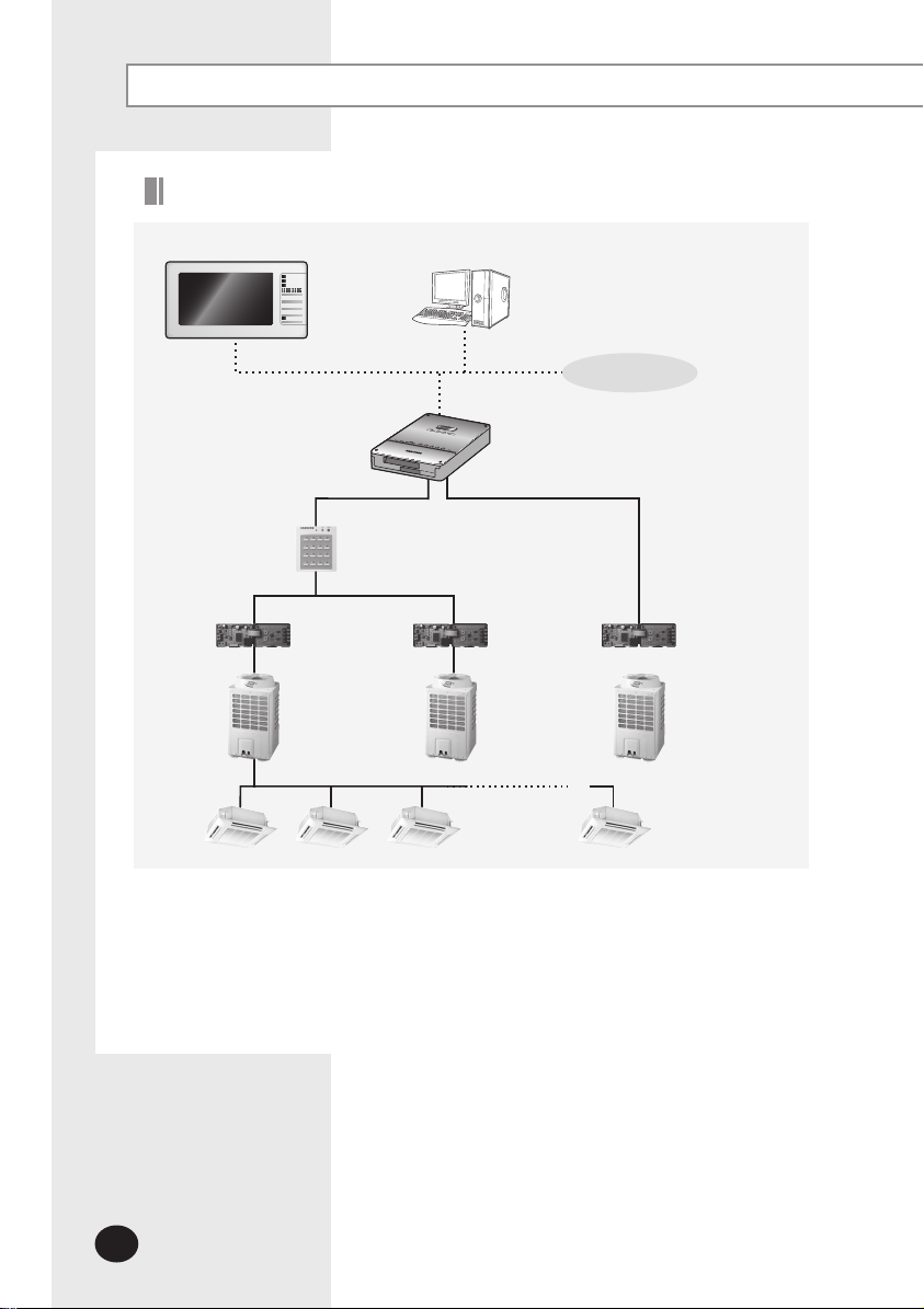
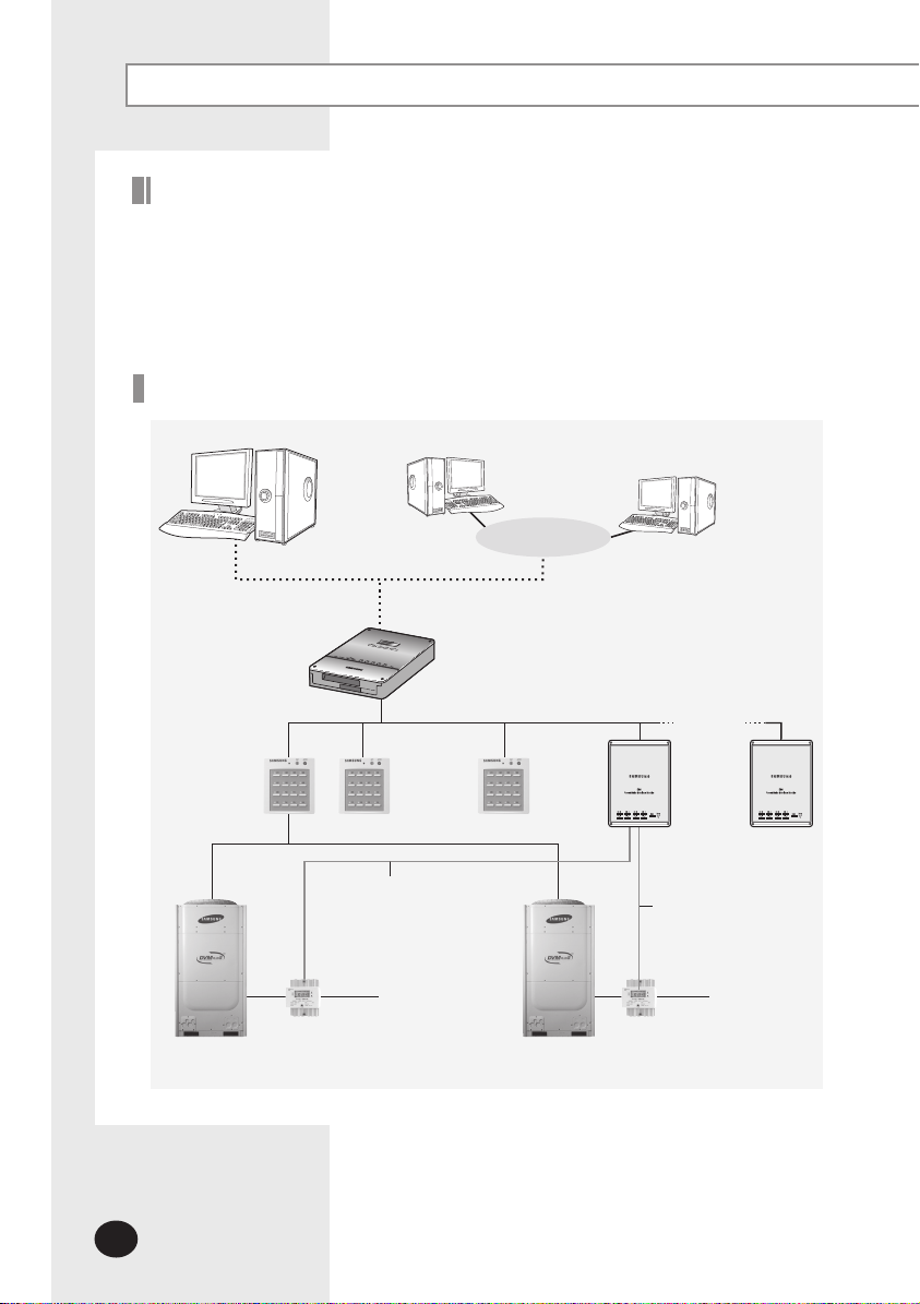
System Configuration
S-NET mini
Centralized
controller
Interface module
S-NET 3
DMS2
ⓐ ⓑ
Interface module
Internet
Interface module
Connecting centralized controller and DMS2 (ⓐ type )
You can control up to 16 centralized controllers and 256 indoor units using DMS2.
Connecting interface module and DMS2 (ⓑ type)
- You can control up to 80 interface modules and 256 indoor units using DMS2.
※ 16 interface modules can be connected to RS485 communication channel of DMS2.
- The more interface modules are connected, the longer time takes for tracking.
Page 9
E-9
When connecting centralized controller and interface module to the DMS2 of same
communication channel, only one of them will communicate according to the
communication channel mode setting of [System Settings]
[Tracking].
Therefore, do not connect the centralized controller and interface module to the same
communication channel.
If you set the communication channel mode as interface module, virtual centralized
controller address will be assigned. Therefore if you connect centralized controller
at the same time and set the address as virtual centralized controller address, it may
cause trouble for bringing device information.
Channel 0: Virtual centralized controller 11,
Channel 1: Virtual centralized controller 12,
Channel 2: Virtual centralized controller 13,
Channel 4: Virtual centralized controller 14,
Channel 5: Virtual centralized controller 15
Web Browser Specification
Install Windows XP SP2, Windows 2000 SP4 or later version
Install Internet Explorer 7.0 or later version
※ You can use Internet Explorer 6.0 but it is not recommended.
Install Silverlight 2.0 or later version
Note
Visit internet homepage (http://www.microsoft.
com/silverlight/) to download Silverlight. Or you can
download it through the download link which is noticed
automatically when the PC is connected to the Internet
and you access to DMS2 for the first time.
Silverlight operates normally with Windows XP SP2 or
later version.
It may not operate normally with former version of
Windows.
Computer Settings for DMS2 Connection
All settings of DMS2 will be arranged in web page which built in
DMS2.
You should access to DMS2 IP to use DMS2 web page.
There are 2 ways to access DMS2 IP.
(For about settings, refer to installation manual.)
Static IP setting
Dynamic IP(DHCP) setting
Page 10
E-10
Main Function
Interface with Upper Level Controller
The DMS2 receives/manages setting and control data from the
upper level controller and sends the received data to the lower
level system.
The upper level controllers of the DMS2 are the S-NET series
and the connectible S-NET series are S-NET 3, S-NET mini and
RMS.
S-NET 3: System air conditioner controlling and monitoring
program that is used by installing on a PC.
S-NET mini: System air conditioner controlling and monitoring
device with touchscreen
RMS: A device which supervises operation status and break
down status by connecting to DMS2 for system air
conditioner remote service. If break down is detected,
it notifies service agent and makes fast service possible.
Save Trouble History
The DMS2 saves at most 1024 cases of trouble history.
If the number of errors exceeds 1024, only the latest 1024 cases
are stored by deleting the oldest trouble history.
Device name, address, error occurrence time, error solvation
time, trouble history will be saved. You can check it in web
page or upper controller.
When an error occurs, it sends trouble history to e-mail saved
in DMS2.
Device Type
Indoor Unit
Outdoor Unit
Communication error
such as centralized controller
Indoor unit communication error
Indoor unit sensor related error
Other errors
Outdoor unit communication error
Pipe inspection error
Outdoor unit sensor related error
Outdoor unit related other errors
Option device related communication
error
Page 11
E-11
Set and Run Schedule
The schedule function of the DMS2 can be set through the Web
or using the upper level controller. 1day/Everyday/Every week
schedules can be set.
Each schedule can be used selectively by using the run
schedule/stop schedule order.
At most 256 schedules can be set.
Indoor unit control is possible at least 1 minute of interval by
set schedule.
Item Content Remark
Schedule Period Starting and ending date of a schedule
Exception Day
Setup
Indoor unit to
be applied
Event
Set an exception day within a schedule period to
ignore the schedule control
Select indoor units to receive schedule control
Set indoor unit operation modes
- Indoor unit On time
- Indoor unit Off time
- Set temperature
- Operation mode: Auto/Cool/Dry/Fan/Heat
- Remote control usage ON/OFF/Level1
- Fan speed: Auto/Low/Mid/High
- Air flow: None/Vertical/Horizontal/All
- ERV operation mode: Auto/HeatEx/ByPass/Sleep
- ERV Fan speed: Low/High/Turbo
Weekly Repeat:
Maximum 10 events
per day
Daily Repeat:
Maximum 70 events
Page 12
E-12
Main Function (Continued)
Save Integrated Power Distribution Data
The DMS2 calculates and distributes the power consumed by each indoor unit by
receiving the total power usage from the watt-hour meter interface modules (SIM/PIM)
and taking into account the operation status of the indoor units.
The DMS2 saves at most 1 year of data. After a year, the oldest data is deleted and
the latest data is saved. This data can be checked through the built-in Web page of
the DMS2 or by S-NET 3.
System Architecture
S-NET 3
Centralized controller
Watt-hour meter
DMS2
Up to
8 units
Internet
Web Client
Up to
8 units
SIM /PIM
Up to
8 units
Watt-hour meter
SIM /PIM
Page 13
E-13
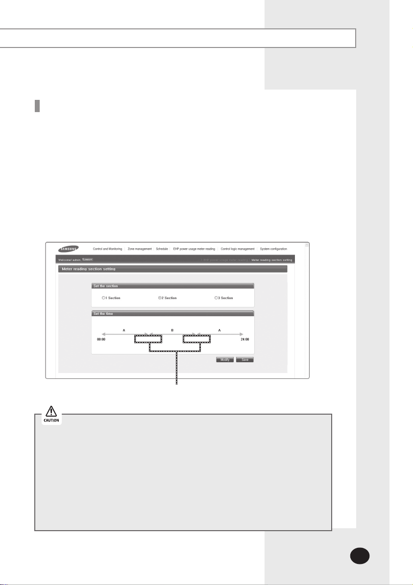
Time Segmentation
Time segmentation is used to divide 24 hours into different sections and to distribute
power according to each section.
This function is used when the power consumption fee is different according to
different time slots or when a building is charged differently depending on the
consumption time.
Time can be divided into 1 section (A), 2 sections (A,B,A), and 3 sections (A,B,C,B,A).
When the time is divided into 2 or 3 sections, you should install S-NET 3 to calculate or
check the distributed power on each section.
DMS2 will always show the result of the power distribution on section 1, regardless of
section 2 or 3.
Input manually (When setting 2 sections and 3 sections)
If communication error occurs between DMS and the lower level controllers,
actual power consumption and the result of power distribution value may not be
same. Make sure to solve communication error status.
- Communication error example : Between DMS2 and SIM/PIM
Between SIM/PIM and Watt-hour meter
Between DMS2 and Centralized controller
Between Centralized controller and interface
module
Between Interface module and indoor/outdoor
units Between DMS2 and interface module
Page 14
E-14
Starting DMS2
Starting DMS2
Current time setting
Set the current time of DMS2 system.
“2009/01/01 01:01:01” is factory setting. Set the current time as DMS2 system time.
You can set DMS2 time in [System Settings]
(Refer to page 104~105)
If DMS2 time does not set as the current time, DMS2 may cause malfunction when
using Schedule or control logic management.
Connecting centralized controller & interface module
(1) Make sure that centralized controller communication cables(C1, C2) or interface module
communication cables(R1, R2) are connected.
For communication between DMS2 and centralized controller/interface module,
centralized controller communication cable(C1, C2) or interface module
communication cable(R1, R2) should be connected.
(2) Execute tracking.
DMS2 communicates with centralized controller and interface module and brings
information about installed indoor unit and outdoor unit.
After tracking, you can use indoor unit control and other menu.
For tracking, refer to [System Settings] [Tracking] (Refer to page 120~130)
[System environment setting]
Page 15
E-15
Access to DMS2 & Login
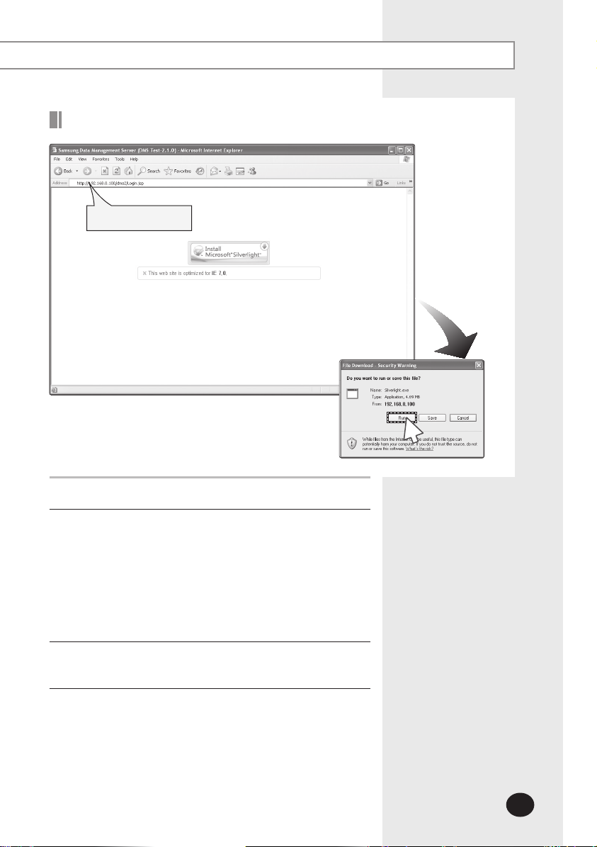
Address bar
Run internet explorer on your computer.
1
Enter IP address (http://192.168.0.100) on the address bar,
2
and then press [ENTER].
If it is the first access to DMS2, “Install Microsoft Silverlight”
message will be displayed.
- The message will not appear if Microsoft Silverlight have
already installed.
If the message window and login screen does not
appear, check PC setting status.
3
Click [Run] and continue installation.
3
Access to DMS2 again after installation.
Page 16
E-16
Starting DMS2 (Continued)
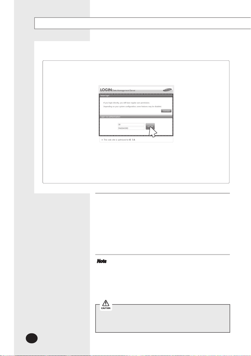
4
Enter ID and password when DMS2 main web page appears.
4
Then click [LOGIN].
The default DMS2 user ID is 'admin' and password is '1234'.
Click [Connect] to log in as a regular user.
Depending on authorization settings which set by the
administrator, access to some functions may be restricted.
To edit user authorization, refer to [System Settings]
[User authorization management]. (Refer to page 87)
Note
Only authorized users can access to web page.
Fewer than 5 concurrent users are recommended
DMS2 manager should change ID and password for
Logout: To log out, click [LOGOUT] on the top of the
because connection speed may slow down.
security and management. (Refer to page 85)
menu.
Silverlight will run normally with Windows XP SP2 or later
version. With former version of Windows, DMS2 may not
operate normally.
Page 17
E-17
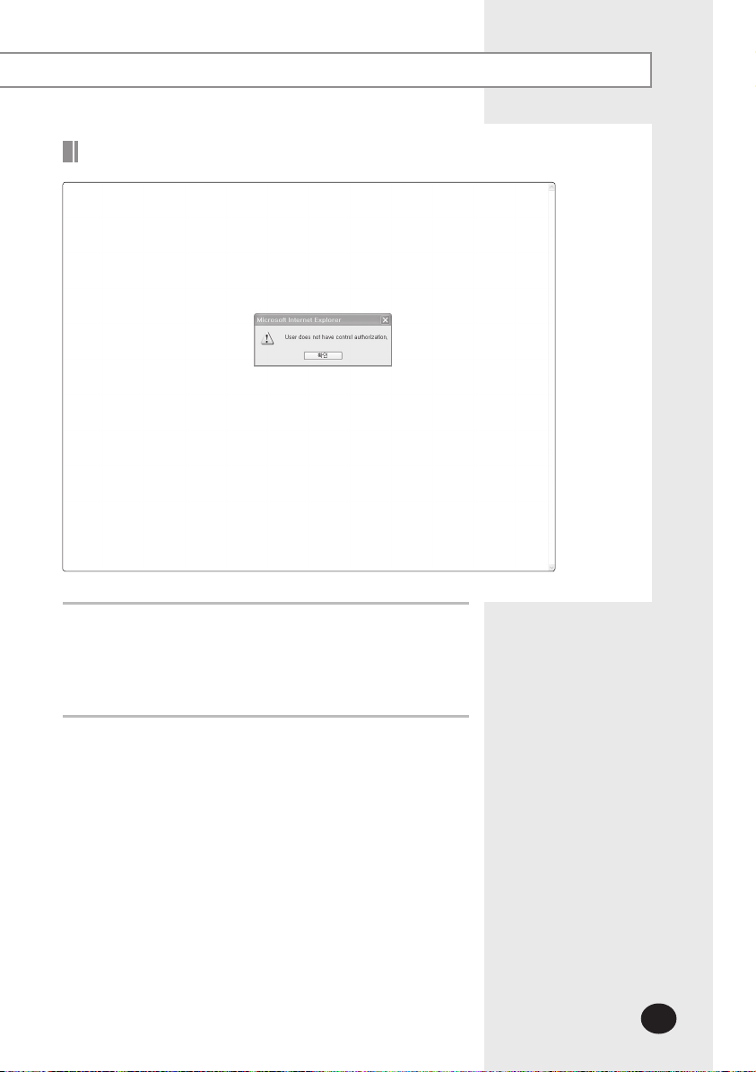
Logged-in User with No Authorization
When the screen above appears, ask for manager.
1
Depending on control authorization setting, there can be
a user who does not have control authorization.
Above screen will appear when the logged-in user does
not have control authorization.
Page 18
E-18
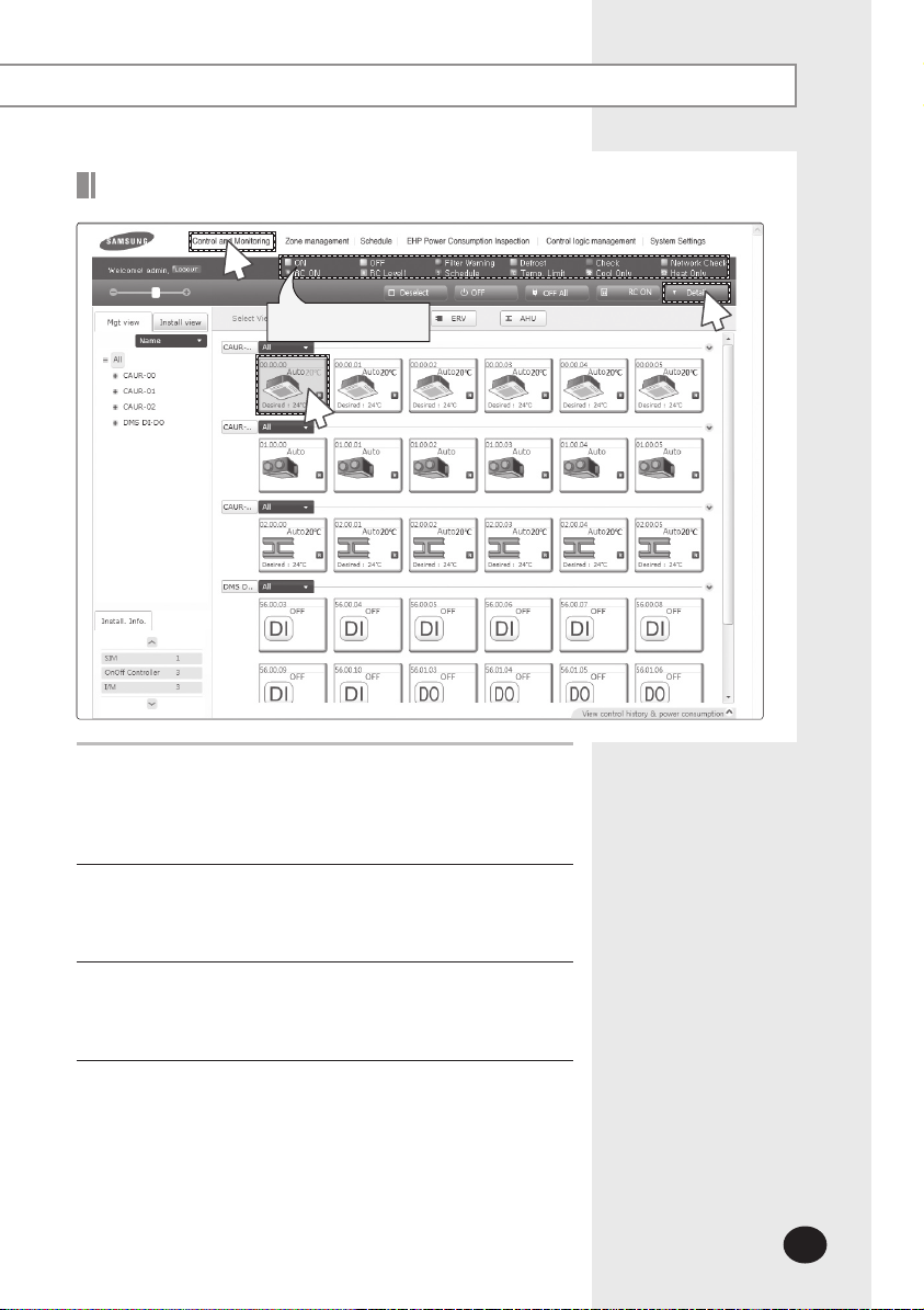
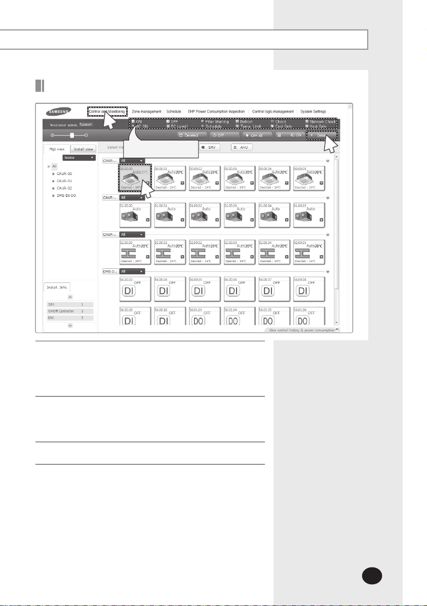
Control and Monitoring
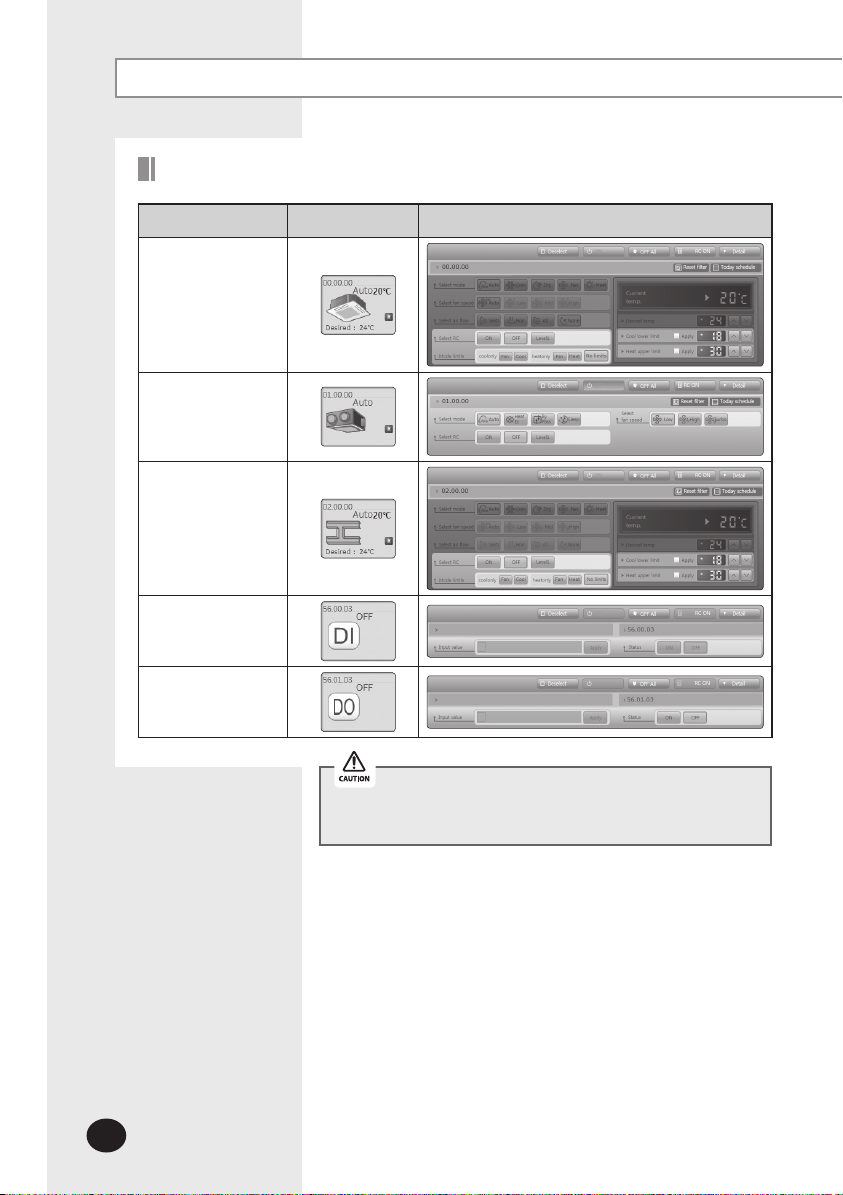
DMS2 Controllable Devices
Type Display Remote controller (Controlling range)
Indoor unit
display icon
ERV display icon
AHU display icon
DI(Digital Input)
display icon
DO(Digital Output)
display icon
If the user select several devices, the remote controller of
last selected device will be displayed on the screen.
Page 19
E-19
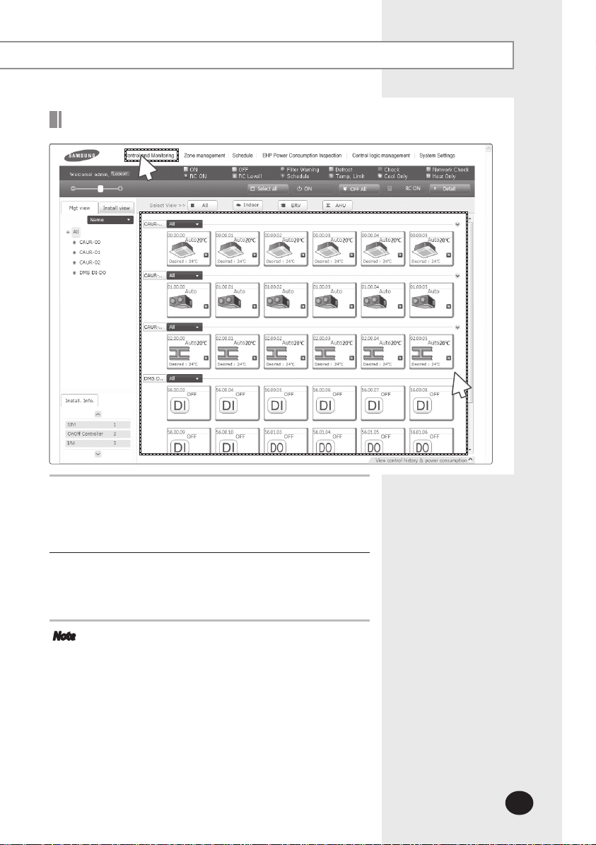
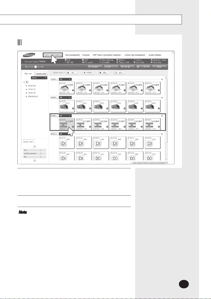
Monitoring Indoor Unit Operation Status
1
Click [Control and Monitoring] when DMS2 web page menu
1
screen appears.
[Control and Monitoring] screen will appear when you
log-in to DMS2 web page.
2
Check the current status of all devices.
2
You can check current status of all installed indoor units,
ERV, AHU, DI and DO.
Note
When the advanced functions (such as Sleep mode,
Energy saving function) are selected through wired/
wireless remote controllers or indoor unit panel,
set operation mode on the remote controllers and
DMS2 may be displayed differently. Also, when
controlling by DMS2, additional functions will be
canceled.
Depending on the model of indoor unit, horizontal/
all air flow control may not be possible. In this case,
vertical or fixed flow will be displayed depending on
indoor unit’s basic operation specification.
Devices such as AHU and ERV will be displayed only
when they are installed.
Page 20
E-20
Control and Monitoring (Continued)
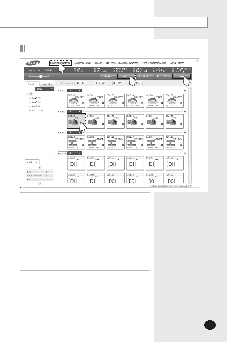
Controlling Indoor Unit
1
Status display window
2
Click [Control and Monitoring] when DMS2 web page menu
1
screen appears.
[Control and Monitoring] screen will appear when you
log-in to DMS2 web page.
Select indoor unit to control.
2
Check the indoor unit status through status display
window.
3
4
Turn the indoor unit on by clicking [ON].
3
Click [Detail].
4
Page 21
E-21
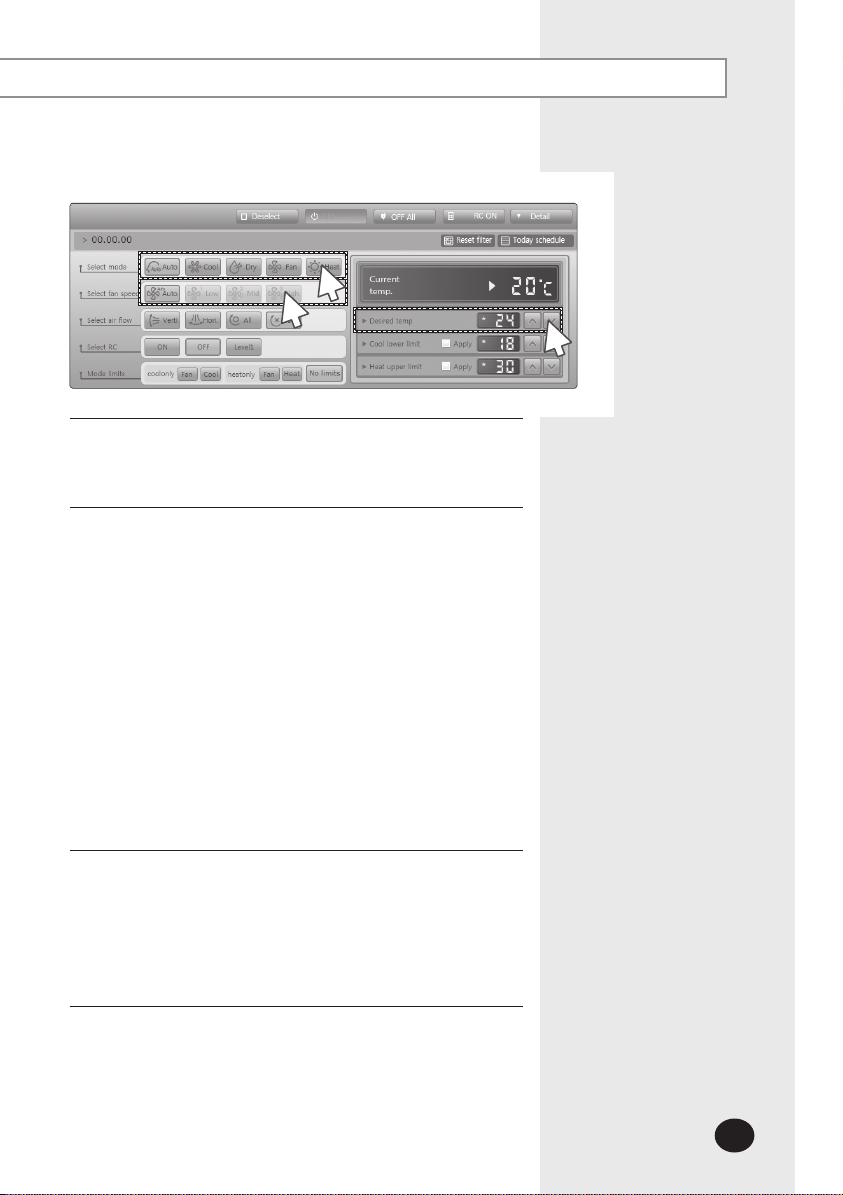
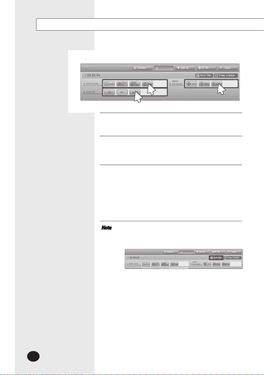
5
7
Select the operation mode.
5
You can select Auto, Cool, Dry, Fan or Heat operation
mode.
Click [∧][∨] to set the desired temperature.
6
Each time you click the buttons, the temperature will be
adjusted by 1℃(
1°F).
If Auto/Cool/Dry mode is in operation, you can adjust the
desired temperature in the range of 18℃(65°F)
~
30℃(86°F).
If Heat mode is in operation, you can adjust the desired
temperature in the range of 16℃(61°F)~30℃(86°F)
You cannot adjust the desired temperature in Fan mode.
When the operation mode of indoor unit is Cool or Dry
mode, you cannot set the desired temperature lower than
lower limit temperature if lower limit is enabled.
When the operation mode of indoor unit is Heat mode,
you cannot set the desired temperature higher than upper
limit temperature if upper limit is enabled.
6
.
Select the fan speed.
7
You can select Auto, Low, Mid or High.
If Auto/Dry mode is in operation, fan speed will be set as
Auto fan speed.
If Fan mode is in operation, you cannot select Auto fan
speed.
Page 22
E-22
Control and Monitoring (Continued)
8
9
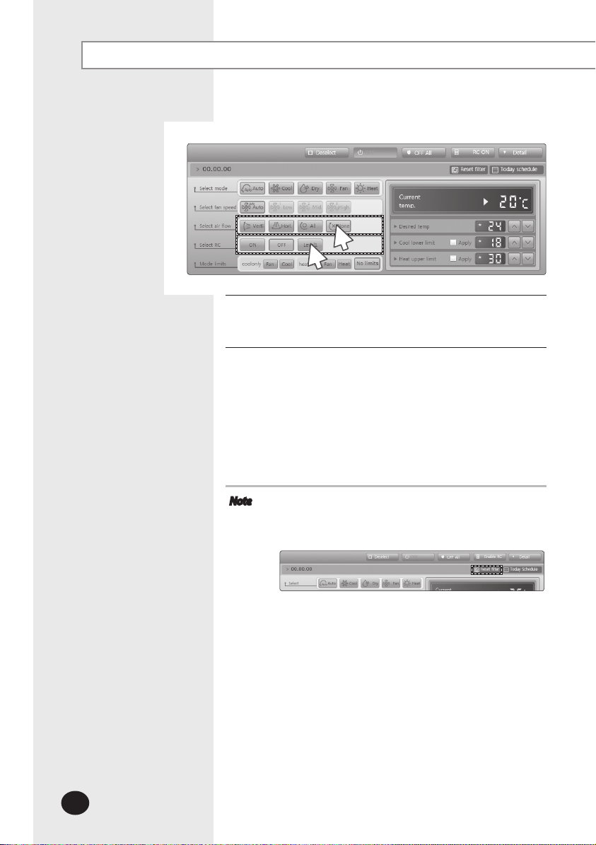
Select the air flow.
8
You can select Vertical, Horizontal, All and None air flow.
Set remote controller settings.
9
You can select ON, OFF and Level1.
When selecting [OFF], indoor unit control by wired/
wireless remote controller and indoor unit panel is not
possible. Indoor unit control is only available in DMS2 web
page.
Click [ON] when you want to use wired remote controller
in each room.
Note
When filter warning sign is displayed on indoor unit
status window
Select the indoor unit and click [Reset filter].
Filter warning will be released.
Make sure that each indoor unit must be turned on to
control.
Selecting remote controller, reset filter, operation
mode limits, setting lower/upper temperature limit are
possible even if the power of indoor unit is off.
Some air flow option may be restricted depending on
the indoor unit model.
Page 23
E-23
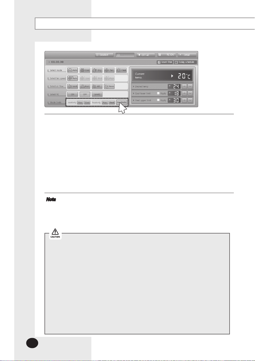
Indoor Unit Operation Mode Limit
1
Status display window
2
Click [Control and Monitoring] when DMS2 web page menu
1
screen appears.
[Control and Monitoring] screen will appear when you
log-in to DMS2 web page.
Select indoor unit to control.
2
Check the indoor unit status through status display
window.
3
Click [Detail].
3
You can check and set operation mode, fan speed, air flow
and desired temperature of selected indoor unit.
Page 24
E-24
Control and Monitoring (Continued)
4
Set operation mode limit.
4
You can select 'Cool only(Fan, Cool)’, ‘Heat only(Fan, Heat)’ and ‘No limits’.
- Cool only (Fan, Cool): If cooling only indoor unit operates in heat mode, indoor
- Heat only (Fan, Heat): If heating only indoor unit operates in cool mode, reset the
- No limits: You can use cooling only and heating only with no limits.
- Ex: If the cooling only indoor unit (with Fan mode set as alternative operation
mode) operates in heating mode, DMS2 will detect it and reset the indoor unit
in Fan mode.
Note
Operation mode limits setting is not available in ERV.
Mixed operation can occur regardless of operation mode limits setting.
If indoor unit with operation mode limit is in mixed operation, DMS2 solves
mixed operation status automatically by controlling the indoor unit in set
operation mode.
unit operation will be reset to the alternative operation
mode.
indoor unit as set operation mode.
In the following circumstances, all indoor units under the same outdoor unit
should be set to the same operation mode limits. Mixed operation can occur
continuously when you set some of indoor unit to cool only and the other to heat
only.
- If the centralized controller is MCM-A202 and is in group mode
- If the centralized controller is in group mode and the interface module is
MIM-B13 or MIM-B04A
Except above circumstances, DMS2 changes the operation mode limit of all
indoor units under the same outdoor unit to same operation mode limit.
- If the centralized controller is in group mode and is above MCM-A202A and all
the interface modules under the centralized controller are above MIM-B13A
- If the centralized controller is in individual mode
If you set the cooling only indoor unit’s operation mode limit to heating only,
DMS2 may display Heating
Cooling alternately.
Page 25
E-25
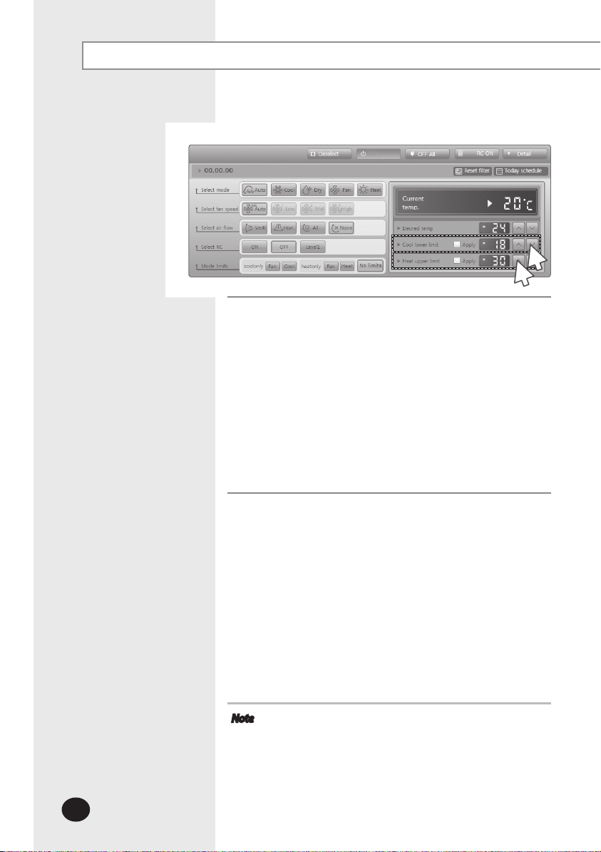
Setting Lower/Upper Temperature Limit of Indoor Unit
1
Status display window
2
Click [Control and Monitoring] when DMS2 web page menu
1
screen appears.
[Control and Monitoring] screen will appear when you
log-in to DMS2 web page.
Select indoor unit to control.
2
Check the indoor unit status through status display
window.
3
Click [Detail].
3
Page 26
E-26
Control and Monitoring (Continued)
Set lower temperature limit by pressing [∧] and [∨].
4
You can set lower temperature limit by checking 'Apply'.
When indoor unit is operating in cool mode, DMS2
controls indoor unit as lower temperature limit if the
desired temperature is lower than lower temperature limit.
Lower temperature limit can be set in the range of
18℃(65°F)~30℃(86°F)
Check 'Apply' to apply the Lower temperature limit setting.
When indoor unit is operating in Cool or Dry mode and
the low temperature limit is applied, you cannot set the
desired temperature lower than the lower temperature
limit.
4
5
.
Set upper temperature limit by pressing [∧] and [∨].
5
Check 'Apply' to apply the upper temperature limit setting.
When indoor unit is operating in heat mode, DMS2
controls indoor unit as upper temperature limit if the
desired temperature is higher than upper temperature
limit.
Upper temperature limit can be set in the range of
16℃(61°F)~30℃(86°F)
Check 'Apply' to apply the lower temperature limit setting.
When indoor unit is operating in Heat mode and the
upper temperature limit is applied, you cannot set the
desired temperature higher than the upper temperature
limit.
Note
Temperature limit in Cool/Heat mode setting is not
available in ERV.
If the indoor unit is in Auto(Cool)/Auto(Heat) mode,
lower/upper temperature limit will be applied when
the indoor unit is operating in Auto mode.
However, if the upper temperature limit is set to
16°C(61°F)~17°C(64°F), the upper temperature limit in
Auto(Heat) mode is 18°C(65°F).
.
Page 27
E-27
Monitoring AHU Operation Status
1
2
Click [Control and Monitoring] when DMS2 web page menu
1
screen appears.
[Control and Monitoring] screen will appear when you
log-in to DMS2 web page.
Check current status of AHU.
2
Note
To control AHU, refer to ‘Controlling indoor unit’ steps.
- AHU’s fan speed is fixed as high. (Refer to page 20~22)
- You cannot set air flow of AHU.
To set the operation mode limit of AHU, refer to ‘Indoor
To set the lower/upper temperature limit of AHU,
unit operation mode limit’ steps. (Refer to page 23~24)
refer to ‘Setting lower/upper temperature limit of
indoor unit’ steps. (Refer to page 25~26)
Page 28
E-28
Control and Monitoring (Continued)
Monitoring ERV Operation Status
1
2
Click [Control and Monitoring] when DMS2 web page menu
1
screen appears.
[Control and Monitoring] screen will appear when you
log-in to DMS2 web page.
Check current status of ERV.
2
Page 29
E-29
Controlling ERV
1
2
Click [Control and Monitoring] when DMS2 web page menu
1
screen appears.
[Control and Monitoring] screen will appear when you
log-in to DMS2 web page.
Select an ERV to control.
2
Check ERV status through status display window.
3
4
Turn ERV on by pressing [ON].
3
Click [Detail].
4
Page 30
E-30
Control and Monitoring (Continued)
5
7
Select the operation mode.
5
You can select Auto, HeatEx, By pass and Sleep.
Select the fan speed.
6
You can select Low, High and Turbo.
Fan speed is set to Low in sleep mode.
Set remote controller settings.
7
You can ON, OFF, Level1.
When selecting [OFF], ERV control by wired/wireless
remote controller is not possible. ERV control is only
available in DMS2 web page.
Click [ON] when you want to use wired remote controller in
each room.
Note
When filter warning sign is displayed on ERV status
window
Select the ERV and click [Reset filter]. Filter warning will be
released.
6
Make sure that ERV must be turned on to control.
Selecting remote controller and filter reset are possible
even if the power of indoor unit is off.
Page 31

E-31
Monitoring DMS DI/DO Operation Status
1
2
Click [Control and Monitoring] when DMS2 web page menu
1
screen appears.
[Control and Monitoring] screen will appear when you
log-in to DMS2 web page.
3
Check the current status of DI and DO device.
2
Click [Detail] to see the control window of selected device.
3
Monitor the device through the detail control window.
4
Note
You can control and monitor DI/DO(10 for each) which
built-in DMS2. However, DI 1, 2 and DO 1, 2, 9, 10 are
excluded from controlling and monitoring because
they are used for the internal function of DMS.
Entering ON/OFF becomes impossible for DI device.
Entering ON/OFF becomes possible for DO device.
Entering control value becomes impossible for DI/DO
device.
Page 32

E-32
Control and Monitoring (Continued)
Controlling DMS DO
1
2
3
4
Click [Control and Monitoring] when DMS2 web page menu
1
screen appears.
[Control and Monitoring] screen will appear when you
log-in to DMS2 web page.
Select DO device to control when control and monitoring
2
screen appears.
Check the status of DO device through the status window.
Click [Detail].
3
Control the DO device by clicking [ON]/[OFF].
4
Note
Remote controller setting is not possible for DI/DO device.
Page 33

E-33
Checking the Installation Information
1
2
You can check the installation status of currently connected
device.
Click [Control and Monitoring] when DMS2 web page menu
1
screen appears.
[Control and Monitoring] screen will appear when you
log-in to DMS2 web page.
Check installation status of currently connected device in the
2
installation information tab.
You can check installation information by pressing [∧] and
[∨] buttons.
Page 34

E-34
Control and Monitoring (Continued)
View the Control History & Power Consumption
1
2
3
You can select a device and view control history and power
consumption information.
Click [Control and Monitoring] when DMS2 web page menu
1
screen appears.
[Control and Monitoring] screen will appear when you
log-in to DMS2 web page.
Select a device you want to view control history and power
2
consumption.
Click ‘View control history & power consumption’ tab and
3
wait for a while.
Control history and power consumption information are
received from DMS2.
‘Data receiving’ message will appear on the bottom right
of the tab.
Page 35

E-35
When data reception is completed from DMS2, check control
4
history and power consumption of selected device.
Note
In ‘Control history’, you can check power control and
remote controller usage status.
Operation mode, desired temperature, air flow and fan
speed control shows you the controlled time and type
of control only.
If SIM/PIM is not installed, power consumption
information may not be correct.
- Power consumption information is displayed only
when SIM/PIM is installed.
- If SIM/PIM is removed, value measured with SIM/PIM
will be displayed.
4
Page 36

E-36
Control and Monitoring (Continued)
Cycle Monitoring
1
2
3
You can select an indoor unit and check cycle information.
Click [Control and Monitoring] [Cycle Monitoring] when DMS2 web page menu
1
screen appears.
Click [Select].
2
DMS2 installation information will be displayed.
Select a device to check cycle information.
3
If you select centralized controller, its subordinate outdoor unit which has the
earliest address will be selected.
If you select interface module, its subordinate outdoor unit will be selected.
If you select indoor unit, upper outdoor unit will be selected.
Cycle information of selected outdoor unit and subordinate indoor units.
4
If the status of outdoor unit and indoor unit is changed, status value turns into blue.
Note
You can check all the cycle information on DVM Plus 2 or DVM Plus 3 with the
centralized controller MCM-A202B and interface module MIM-B13B (or higher
version of those devices) only. However, some cycle information may not be
displayed on any other models of outdoor unit.
Page 37

E-37
Indoor Unit Usage Restriction_Operation Limit
1
3
You can set the operation of indoor unit as cooling only and
heating only.
Click [Control and Monitoring] [Indoor unit usage
1
restriction] when DMS2 web page menu screen appears.
Press [Edit] button.
2
Set the limit mode.
3
You can select 'Cool-only’, ‘Heat-only’ or ‘None’.
- For cooling only indoor unit, you can select cool, dry and
fan modes only.
- For heating only indoor unit, you can select heat and fan
modes only.
2
Page 38

E-38
Control and Monitoring (Continued)
4
Set the control mode.
4
If you set the control mode, indoor unit operating in limited operation mode will
be automatically set to operate in pre-set control mode. You can set the different
control mode to each of the indoor units.
- Cooling only indoor unit: You can select fan or cool mode.
- Heating only indoor unit: You can select fan or heat mode.
(Ex: When the indoor unit with fan mode is changed to heat mode, DMS2 will
perceive it and control the indoor unit in fan mode.)
Note
Mixed operation can occur even if you set limit mode.
If the indoor unit with operation mode limit is in mixed operation, DMS2 will
solve the problem automatically by controlling it in control mode.
In the following circumstances, all indoor units under the same outdoor unit
should be set to the same limit mode. Mixed operation can occur continuously
when you set some of indoor unit to cool only and the other to heat only.
- If the centralized controller is MCM-A202 and is in group mode
- If the centralized controller is in group mode and the interface module is
MIM-B13 or MIM-B04A
Except above circumstances, DMS2 changes the limit mode of all indoor units
under the same outdoor unit to same limit mode.
- If the centralized controller is in group mode and is above MCM-A202A and all
the interface modules under the centralized controller are above MIM-B13A
- If the centralized controller is in individual mode
If you set the cooling only indoor unit’s limit mode to heating only, DMS2 may
display Heating
Cooling alternately.
Page 39

E-39
Indoor Unit Usage Restriction_Temperature Limit in Cool/Heat mode
1
2
You can set temperature lower/upper temperature limit in
cool/heat mode.
Click [Control and Monitoring] [Indoor unit usage
1
restriction] when DMS2 web page menu screen appears.
Press [Edit] button.
2
Page 40

E-40
Control and Monitoring (Continued)
3
Set the lower/upper temperature limit.
3
You can set lower/upper temperature limit by selecting
'Enable'/'Disable'.
If desired temperature is lower than lower limit
temperature when the indoor unit is operating in cool
mode, DMS2 controls indoor unit to lower temperature
limit.
If desired temperature is higher than upper limit
temperature when the indoor unit is operating in heat
mode, DMS2 controls indoor unit to upper temperature
limit.
Lower temperature limit range: 18℃(65°F)~30℃(86°F)
Upper temperature limit range: 16℃(61°F)~30℃(86°F)
If the indoor unit is in Auto(Cool)/Auto(Heat) mode, lower/
upper temperature limit will be applied when the indoor
unit is operating in Auto mode.
However, if the upper temperature limit is set to
16°C(61°F)~17°C(64°F), the upper temperature limit in
Auto(Heat) mode is 18°C(65°F).
4
Click [Save].
4
Indoor unit usage restriction setting will be saved.
Page 41

E-41
Checking the Trouble History
1
Click [Control and Monitoring] [Trouble history]
1
when DMS2 web page menu screen appears.
Check all the trouble history.
2
You can check address, device type, occurrence time,
resolution time, code number and status.
3
You can check detailed information on trouble history by
3
selecting the item in the list.
Note
DMS2 saves maximum 1024 trouble histories.
If the number of history exceeds 1024, DMS2 will delete
the oldest history first.
If the same code trouble is detected repeatedly in the
same device on the same day, trouble history will be
shown as 1 case. If it occurs more than 2 times,
‘Resolution time’ may change every time you check.
And the number of repetition will be displayed in
‘Status’ field.
Page 42

E-42
Control and Monitoring (Continued)
Checking the Trouble History by Date
1
3
DMS2 saves maximum 1024 trouble histories. If the number
of history exceeds 1024, DMS2 will delete the oldest history
first.
Click [Control and Monitoring] [Trouble history]
1
when DMS2 web page menu screen appears.
Enter the time period you want to check.
2
Enter year/month/day in order.
Click [Search].
3
You can check address, device type, occurrence time,
resolution time, code number and status in the entered
period.
2
4
You can check detailed information on trouble history by
4
selecting the item in the list.
Page 43

E-43
Deleting the Trouble History
1
2
Click [Control and Monitoring] [Trouble history]
1
when DMS2 web page menu screen appears.
Select trouble history you want to delete.
2
Click [Delete].
3
Click [OK] from the confirm window. Selected trouble
history will be deleted.
3
Page 44

E-44
Control and Monitoring (Continued)
Checking the Operation Status
1
3
You can check operation status of indoor unit which is
controlled by DMS2.
4
Click [Control and Monitoring] [Checking operation status]
1
when DMS2 web page menu screen appears.
Check the operation history.
2
You can check the device type, occurrence time, control
unit, control type, and controlled device address of
indoor unit which is controlled by DMS2 and subordinate
controller.
You can check operation status by entering date.
3
Enter year/month/day then click [Search]. You can check
control histor y that occurred on the entered date.
You can check detailed control history which is controlled by
4
the command by pressing control history in the list.
Note
DMS2 saves the information of operation history for 180 days.
However, it varies depending on saving space of DMS2.
Page 45

E-45
Zone Management
Zone Setting & Edit – Individual/Group Initialization
1
3
2
Click [Zone management] [Zone Setting & Edit] when DMS2 web page menu screen
1
appears.
Same screen will be displayed even if you click [Zone management] only.
Initialize the indoor unit organization as individual by clicking [Individual].
2
Individual initialization reorganizes connected indoor unit based on installation address.
Initialize the indoor unit organization as group by clicking [Group].
3
Group initialization reorganizes connected indoor unit based on RMC address.
After group initialization, indoor units are displayed as one device when
upper zone is selected in the [Control and Monitoring] screen.
When editing zone after group initialization, moving in group is only allowed.
After group initialization, subordinate devices cannot be moved individually to
the other zone.
Note
Only the user who has authorization to edit all zones can use zone initialization.
- To the user who has no authorization to use zone initialization and manage
structure, button will not be displayed.
If the user does not have authorization to edit zone, [Inidividual], [Group] and
[Zone edit] will not be displayed.
Page 46

E-46
Zone Management (Continued)
Zone Setting & Edit – Setting the User Authorization
1
2
Click [Zone management] [Zone Setting & Edit] when DMS2 web page menu
1
screen appears.
Same screen will be displayed even if you press [Zone management] only.
3
Set user authorization for each zone.
2
If the user has no authorization for the zone, controlling and monitoring of the
zone is restricted.
The user who is allowed to control and monitor zone has ‘’ sign.
Click [Save] to save.
3
The user of currently selected zone is selected in the screen.
You should set the authorization for controlling and monitoring the zone when the
user is added.
If you do not set the authorization for zone after adding a user, the zone will not be
displayed even if the user logged in.
Setting the user authorization is valid only for the zone displayed on the screen. If you
select the other zone setting without clicking save button after changing the setting,
user authorization for previously selected zone will be gone.
When initializing zone, all rights are given to all users.
Page 47

E-47
Zone Setting & Edit – Zone Edit
1
2
Click [Zone management] [Zone Setting & Edit] when
1
DMS2 web page menu screen appears.
Same screen will be displayed even if you press
[Zone management] only.
Click [Zone Edit].
2
Zone edit screen will be displayed.
Page 48

E-48
Zone Management (Continued)
3
6
7
4
5
8
Click [▼] to set viewing option of zone edit list.
3
You can select from viewing by 'Name’, ‘Address’ and ‘Address & Name'.
Edit item you want.
4
Create in the
above
Create in the
below
Create the sub
zone
Remove
Move up Move up the selected zone or indoor unit.
Move down Move down the selected zone or indoor unit.
Move to upper
level
Rename
Cut Cut to move the selected zone or indoor unit,
Paste Move the cut zone or indoor unit to the selected zone.
Create a new zone on top of the selected zone.
Create a new zone under the selected zone.
Create a zone one step lower than the user selected.
You cannot create a zone under 5 steps in zone edit.
Remove selected zone. If the selected zone includes device,
the device will move to the top step.
Move the selected zone or indoor unit to the upper level.
Rename the selected zone or indoor unit.
You can use maximum 16 letters.
Page 49

E-49
Click [Remove disappeared] to remove all disappeared devices which were found
5
after tracking.
Change zone properties.
6
You can select “General”, “AHU”, and “Group”.
Mode Property name Description Remarks
Virtual group which is managed by
Individual
initialization
mode
Group
initialization
mode
General
Group
AHU
General
Group
AHU
installation address, not by RMC
address
The user can create and delete zone.
Not applicable.
( Only supported in group initialization
mode.)
Virtual group which manages AHU kit
in general zone.
The user can create and delete.
Virtual group which is set and
managed by the user.
The user can create and delete.
Virtual group which is managed by
installation address, not by RMC
address.
The user cannot create and delete.
DMS2 creates it automatically.
Virtual group which manages AHU kit
in general zone.
The user can create and delete.
Not applicable.
( Only supported in group initialization
mode.)
It will be displayed as single device in
the control and monitoring screen, and
it can be controlled as single device.
You cannot move subordinate device
to the other zone.
It is displayed like as one device in the
control and monitoring screen and can
be controlled.
You cannot move subordinate device
to the other zone.
It is displayed like as one device in the
control and monitoring screen and can
be controlled.
You cannot move subordinate device
to the other zone.
-
-
Click [Apply].
7
Edited zone structure will be applied.
To cancel the setting, click [Cancel].
8
Page 50

E-50
Schedule
Creating New schedule
1
2
You can set, edit, delete and use the schedules for air
conditioner control.
Click [Schedule] [Schedule setting] when DMS2 web page
1
menu screen appears.
Click [Register] in the schedule setting screen.
2
Note
It is not available to provide the schedule information to
BMS system.
Page 51

E-51
3
4
5
Enter the schedule name when the schedule setting screen
3
appears.
Select schedule period you want by clicking calendar.
4
If you select 'No limit' when setting end date, it means
there is no period and it displays Dec 31st, 9999.
To set the end date, remove the check of ‘No limit’ or select
calendar icon which is on the right side of date.
To set an exception date in the schedule period, click
5
[Add exception] and select date(month/day) you want.
Select an exception date on the calendar window.
Page 52

E-52
Schedule (Continued)
6
To cancel the added exception date, select the exception
6
date it(
) and click [Delete].
Maximum 365 exception dates can be saved.
Page 53

E-53
7
8
Click [Add indoor] to select an indoor unit to apply.
7
All the connected indoor units list will be displayed.
8
To cancel the indoor unit selection, select () the indoor
unit again and click [Delete].
Page 54

E-54
Schedule (Continued)
9
10
Click [∨] to select repeat schedule you want and set an event.
9
You can select 'Weekly', 'Everyday' and '1day'.
However, the starting and end date should be same when you select '1day'.
Enter 4 digits for ON/OFF time setting.
Ex) 8:00 0800, 9:30 0930
Remote controller setting is as follows.
●
ON: Controlling indoor unit using wired/wireless remote controller or
indoor unit panel in each room is possible.
●
OFF: Controlling indoor unit using wired/wireless remote controller or
indoor unit panel in each room is not possible.
●
Level1
- ON by centralized controller, DMS2: Controlling indoor unit using wired/wireless
- OFF by centralized controller, DMS2: Controlling indoor unit using wired/wireless
Click [Add] to add event.
To delete event, select an event() and click [Delete].
Maximum 70 events can be set per 1 schedule. In case of week schedule, 10 events per
1 day can be set.
If starting and end time of schedule event are repeated, only the schedule event
which is made earlier will be executed.
remote controller or indoor unit panel in each
room is possible.
remote controller or indoor unit panel in each
room is not possible.
Page 55

E-55
Click [Save].
10
Set schedule information is saved in DMS2.
Click [Cancel] to cancel schedule setting.
Note
If you select dry mode among basic modes, auto fan
speed is only available.
When the operation mode is ‘Auto’, fan speed is always
set to ‘Auto’.
When the operation mode is ‘Fan’, you cannot control
fan speed as ‘Auto’.
When the operation mode is ‘Dry’, fan speed is always
set to ‘Auto’.
When you select sleep mode among ERV modes, ‘Mid’
fan speed is only available.
The desired temperature range is as below.
- Celsius: 16°C~30°C in heating mode, 18°C~30°C in
cooling mode
- Fahrenheit: 61°F~86°F in heating mode, 65°F~86°F in
cooling mode
If the tracking is not completed, schedule setting is not
possible. To use proper schedule function, make sure to
complete tracking with installation engineer.
Page 56

E-56
Schedule (Continued)
Editing Schedule
2
1
2
1
3
Click [Schedule] [Schedule setting] when DMS2 web page
menu screen appears.
Select the schedule to edit.
For the currently operating schedule, you can only
check it.
Click [Edit].
3
Edit schedule when the schedule edit screen appears.
Editing schedule method is same as “Creating New
Schedule”. (Refer to page 50~55)
Page 57

E-57
Deleting Schedule
1
2
3
Click [Schedule] [Schedule setting] when DMS2 web page
1
menu screen appears.
Select the schedule to delete.
2
Click [Delete].
3
Click [OK] in confirm window and selected schedule will
be deleted.
Deleting schedule is possible only when the schedule is in
stop status.
If you want to delete schedule which is currently applied,
stop applying the schedule first.
Page 58

E-58
Schedule (Continued)
Applying schedule
2
3
1
2
3
1
Click [Schedule] [Schedule setting] when DMS2 web page
menu screen appears.
Select the schedule you want to use.
Use schedule functions by clicking [Run] and [Stop].
To apply the selected schedule, click [Run].
To stop the selected schedule, click [Stop].
Note
To stop all schedules, click [Stop all].
- Currently applied schedule will be stopped.
Page 59

E-59
Checking Schedule Control History
1
2
3
Click [Schedule] [Checking schedule control history] when
1
DMS2 web page menu screen appears.
Select a date to check and then click [Search].
2
Only executed schedules can be searched.
You can check detailed setting by clicking the schedule
3
name.
Note
DMS2 saves the information or schedule control history
for 180 days.
However, it varies depending on saving space of DMS2.
Page 60

E-60
EHP Power Consumption Inspection
Checking Inspection Result (with SIM/PIM)
1
2
You can check the operation history and power consumption saved in DMS for each
indoor unit.
Click [EHP Power Consumption Inspection] [Check inspection result] when DMS2 web
1
page menu screen appears.
Set date and search condition (power consumption/proportion/individual indoor unit by
2
date) when inspection result screen appears.
Select year/month/day in order.
Based on DMS2 time, you can check up to 365 days of watt-hour meter value.
Click [Search].
3
Inspection result will be displayed depending on set period and searching condition.
You can check power consumption only when watt-hour meter is connected.
If watt-hour meter is not connected, you can check operating proportion by indoor
unit only .
3
4
Click [Save as Excel].
4
Searched inspection result will be saved as MS Excel file.
Note
For data management, it is recommended to save indoor unit inspection result
periodically.
Page 61

E-61
Checking Inspection Result (without SIM/PIM)
1
2
3
Click [EHP Power Consumption Inspection] [Check
1
inspection result] when DMS2 web page menu screen
appears.
Channel setting by indoor unit must be done in advance.
Set date when inspection result screen appears.
2
Select year/month/day in order.
Based on DMS2 time, You can check up to 365 days of
inspection results.
4
Enter power consumption value during the period.
3
Virtual channel is value which is set in channel setting by
indoor unit.
Click [Calculate].
4
Power consumption by indoor unit during the period will
be displayed.
Page 62

E-62
EHP Power Consumption Inspection (Continued)
Check the power consumption result of the selected period.
5
Due to rounding the actual values, actual input value and
result value may different to each other.
If you want to save the consumption result for selected
period as MS Excel file, click [Save as Excel].
Click [Calculate] to go back to inspection result screen.
Note
For data management, it is recommended to save indoor
unit inspection result periodically.
Page 63

E-63
Setting the Inspection Section
3
Click [EHP Power Consumption Inspection] [Setting the
1
inspection section] when DMS2 web page menu screen
appears.
Click [Edit] when inspection result screen appears.
2
1 section is set as default.
Select a section and enter time by section.
3
You should enter time of section B when selecting
section. And you should enter time if section B and C
when selecting 3 sections.
Correct format of time is HH:MM.
Ex) 4:30 in the afternoon
16:30
1
2
4
Click [Save].
4
Set power section will be saved in DMS2.
If you do not click [Save] , changed setting will not be
saved.
Note
Ex) When selecting 2 sections(A, B, C)
If the border time between A and B is 08:00, section A is
00:00 ~ 08:00,
section B is 08:01 ~ 18:00, and section A again is
18:01 ~ 24:00.
Checking inspection result by section is available in
S-NET 3 only.
Page 64

E-64
EHP Power Consumption Inspection (Continued)
Setting and Checking Watt-Hour Meter
1
3
4
2
Click [EHP Power Consumption Inspection] [Setting and checking watt-hour
1
meter] when DMS2 web page menu screen appears.
Setting watt-hour meter is possible only when SIM/PIM is installed.
Click [Edit] when the setting and checking watt-hour meter screen appears.
2
CT proportion ‘1’ is set as default.
Set name and CT proportion of watt-hour meter.
3
You can use maximum 16 letters.
The range of CT proportion value is positive number from 1 to 5000.
Click [Save].
4
Set watt-hour meter information will be saved in DMS2.
If you do not click [Save], changed setting will not be saved.
Watt-hour meter value shows actual value of currently connected watt-hour meter.
Watt-hour meter value will be updated automatically.
When using CT watt-hour meter, be careful that there can be difference with actual
power consumption as much as CT ratio error.
Page 65

E-65
Checking Kilowatthour History
1
2
3
Click [EHP Power Consumption Inspection] [Setting and Checking watt-hour
1
meter] when DMS2 web page menu screen appears.
Click [Kilowatthour history] when the setting and checking
2
watt-hour meter screen appears.
Select SIM/PIM address and date you want when the kilowatthour history screen
3
appears.
Enter year/month/day in order.
Based on DMS2 time, you can check up to 365 days of kilowatthour history.
Click [Check].
4
Kilowatthour history of set period will be displayed.
4
Page 66

E-66
EHP Power Consumption Inspection (Continued)
Setting and Checking Virtual Channel
1
3
2
4
Click [EHP Power Consumption Inspection] [Setting and
1
checking virtual channel] when DMS2 web page menu screen
appears.
Maximum 128 virtual channels can be set.
Virtual channel is written in (24 ~ 31).(1 ~ 16) format
address.
Ex) 24.1, 25.2, 31.8
Click [Edit] when the setting and checking virtual channel
2
screen appears.
Set the name of virtual channel.
3
You can use maximum 16 letters.
Click [Save].
4
Set virtual channel name will be saved in DMS2.
If you do not click [Save], changed setting will not be
saved.
Page 67

E-67
Channel Setting by Indoor Unit
Click [EHP Power Consumption Inspection] [Channel
1
setting by indoor unit] when DMS2 web page menu screen
appears.
Click [Edit] when the setting channel by indoor unit screen
2
appears.
1
2
Page 68

E-68
EHP Power Consumption Inspection (Continued)
7
8
Check the address and channel information of SIM/PIM which is connected to watt-
3
hour meter.
If 0~7 SIM/PIM units execute tracking, it will be displayed as 16~23 in DMS2.
Below table shows the channel information of the terminal which SIM and watt-
hour meter is connected.
(Terminal block 1 is on the very left side in SIM.)
Terminal block
Location
Top part
Bottom part
PIM: Channel 1 is on the most left side and 8 channels are arranged in a line.
Terminal block 1 Terminal block 2 Terminal block 3 Terminal block 4
1 2 3 4
5 6 7 8
Check the information of indoor/outdoor unit which is connected to
4
watt-hour meter.
Check the SIM/PIM channel(watt-hour meter) information of indoor/outdoor unit.
5
You can set the channel when SIM/PIM is installed in DMS2.
When bringing indoor unit’s power from outdoor unit, set the ‘Outdoor unit SIM
channel’ information only.
( ‘Outdoor unit SIM channel’ is referring to watt-hour meter which is connected to
outdoor unit.)
When bringing indoor unit’s power from the other device, not from outdoor unit,
set the ‘Outdoor unit SIM channel’ and ‘Indoor unit SIM channel’ information.
(‘Indoor unit SIM channel’ is referring to watt-hour meter which is connected to
indoor unit.)
Power distribution will be executed automatically. The user does not need to check
the value of watt-hour meter.
Page 69

E-69
Check the virtual channel information of indoor/outdoor unit.
6
To execute power distribution without SIM/PIM, you should set virtual channel.
When bringing indoor unit’s power from outdoor unit, set the ‘Outdoor unit virtual
channel’ information only.
( ‘Outdoor unit virtual channel’ is referring to watt-hour meter which is connected
to outdoor unit.)
When bringing indoor unit’s power from the other device, not from outdoor unit,
set the ‘Outdoor unit virtual channel’ and ‘Indoor unit virtual channel’ information.
(‘Indoor unit virtual channel’ is referring to watt-hour meter which is connected to
indoor unit.)
The number of virtual channel varies depending on the number of interface
module.
To execute power distribution, you need to check watt-hour meter value manually.
Power distribution using SIM/PIM is more accurate than using indoor/outdoor unit
virtual channel. Therefore, it is recommended to execute power distribution using
SIM/PIM.
Set indoor unit to execute power distribution.
7
If you do not set the watt-hour meter information, the power distribution result of
the indoor unit will be displayed as ‘0’.
Click [Save].
8
Set channel information will be saved in DMS2.
If you do not click [Save], changed setting will not be saved.
Information of watt-hour meter connected to indoor/outdoor unit should be accurate.
If the watt-hour meter information is not accurate when you set channel information
of indoor unit, error may occur in the power distribution result.
You should set SIM/PIM channel information in the indoor unit if you want to execute
power distribution using SIM/PIM. If not, it means that you do not execute power
distribution. In this case, the power distribution result of the indoor unit will be ‘0’.
If the information of watt-hour meter connected to indoor/outdoor unit is changed,
consult with installation engineer.
DMS2 executes power distribution based on set information.
Virtual channel is not available when you use BACnet or LonWorks Gateway function.
Page 70

E-70
EHP Power Consumption Inspection (Continued)
Checking Indoor Unit Operation Time
1
2
Click [EHP Power Consumption Inspection] [Checking
1
indoor unit operation time] when DMS2 web page menu
screen appears.
Select search condition (All indoor units by period/
2
Individual indoor unit by date) when Checking indoor unit
operating time screen appears.
Select year/month/day in order.
Based on DMS2 time, you can check up to 365 days of
operation time.
Click [Search].
3
Operation time will be displayed depending on set period
and condition.
3
4
Click [Save as Excel].
4
Searched operation time result will be saved as MS Excel
file.
Note
For data management, it is recommended to save indoor
unit operation time result periodically.
Page 71

E-71
Control Logic Management
Setting Control Logic
■
Control logic is used in the following situations.
Ex) The current temperature of the lab is higher than 29
The current temperature of the office is lower than 10℃ and you want heating operation
■
Period, day and time are included in specific conditions.
You can set, edit, delete and use control logic for controlling device which is
connected to DMS2.
Click [Control logic management] [Setting control logic] when DMS2 web page
1
menu screen appears.
Apply: Indicates control logic usage status.
Run: Indicates If the control logic is applied and whether the operation conditions
are met.
Ex) If there is logic which says ‘If the current temperature of indoor unit is higher
than 29℃, control indoor unit as cool mode.’, 'Yes' will be displayed when the
indoor unit's current temperature is higher than 29℃. 'No' will be displayed
when the indoor unit's current temperature is lower than 29℃.
℃ and you want cooling operation,
1
2
Click [Register] when setting control logic screen appears.
2
Setting screen is composed of 4 categories.
- Name & time: Set the name and time(period, days, time) to apply of control logic.
- Factor edit: You can edit factor selection which is components of input/output.
- Input: Set the condition which makes control logic perform.
- Output: Set items to be controlled when the conditions of input are met.
Note
If different value is set for same control item of same address’ device, the indoor
unit follows the first control logic set among running control logics.
It is not available to provide the control logic management information to BMS
system.
Page 72

E-72
Control Logic Management (Continued)
3
4
Enter control logic name in the name field when the new
3
control logic setting screen appears.
You can use maximum 16 letters.
Set period, day and time in control logic screen.
4
Select year/month/day in order.
Select a day to run during the control period.
Control logic will be applied only when period, day and
time are united.
If you select ‘Daily’ in day selection, control logic will run
regardless of day.
Page 73

E-73
6
5
Select a factor in the input list.
5
Factor means the target to be controlled or standard item of logic decision.
Select the type of factor.
6
Single: It means 1 device.
Ex) Desired temperature of indoor unit
Arithmetic: It means 2 devices are connected by arithmetic operator.
Ex) Desired temperature of indoor unit 1 – Desired temperature of indoor unit 2
Function: It means several devices are using as value of function.
Ex) Average(Current temperature of Indoor unit 1, Current temperature of Indoor
unit 2, Current temperature of Indoor unit 3)
Page 74

E-74
Control Logic Management (Continued)
7
Select a device.
7
List of device which you can select will be displayed.
Select the device to use as factor.
8
Control and monitoring items will be displayed depending on selected device.
Control and monitoring items are as follows.
Type Item Value Remarks
Indoor unit
ERV
AHU
DI Status On, Off Control impossible
DO Status On, Off
Power On, Off
Current temp. Number Control impossible
Desired temp. Number -
Outdoor temp. Number Control impossible
Operation mode Auto, Cool, Dry, Fan, Heat -
Fan speed Auto, Low, Mid, High -
Air flow Vertical, Horizontal, All, None -
Remote controller usage ON, OFF, Level1
Power On, Off -
Operation mode Auto, HeatEx, Bypass, Sleep -
Fan speed Low, High, Turbo
Remote controller usage ON, OFF, Level1
Power On, Off
Current temp. Number Control impossible
Desired temp. Number -
Outdoor temp. Number Control impossible
Operation mode Auto, Cool, Dry, Fan, Heat
Remote controller usage ON, OFF, Level1
8
-
-
-
-
-
-
-
-
Page 75

E-75
9
11
Select detailed item of factor.
9
Detailed item may be different depending on the type of selected device.
Click [Apply].
10
If you do not click [Apply], changed setting will not be saved.
Select comparison operator.
11
Types of comparison operators: = , =< , => , < , >, ≠
Comparison operator compares factor to standard factor.
10
Page 76

E-76
Control Logic Management (Continued)
12
Select standard value.
12
Select detailed item value of selected factor or factor.
The item varies depending on the left factor when selecting detailed item value
from standard value.
Ex1) Factor : Current temperature of indoor unit 1,
Value of standard value: Enter 29
Ex2) Factor :
When selecting factor from standard value, it must be same with control item of
left factor.
Ex1) Factor : Power of indoor unit 1,
Factor of standard value : Power of indoor unit 2
Ex2) Factor : Current temperature of indoor unit 1,
Factor of standard value : Average current temperature of indoor unit 1 and 2
Select duration time usage.
13
Duration time means the time which the comparing conditions satisfy ‘True’.
The duration time can be set from 1 to 60.
If you select duration time apply, the comparing condition will be 'True'.
To execute, maintain 'True' for duration time.
Note
Only 1 duration time can be set per control logic.
Remote controller usage of indoor unit 1,
Value of standard value: Select one among On, Off and Level1
13
The tolerance range of duration time is maximum 1 minute. If you set the
duration time as 2 minutes, operation will be started between 2 and 3 minutes.
Page 77

E-77
14
15
Select compound factor setting usage.
14
You can use compound factor setting when you give conditions to 2 and 3 input
items.
You can select 1 compound factor from 'AND' and 'OR'.
Select 'AND' if all the input items each should be ‘True'.
Select 'OR' if just 1 input item needs to be 'True'.
Compound factor has priorities in order.
For example, if you set 'OR', 'AND' in order, it means ‘(input item 1 OR input item 2)
AND input item 3’.
Select ‘Select a factor’ in the Output list.
15
Page 78

E-78
Control Logic Management (Continued)
16
17
18
Select type of factor.
16
Single factor can be set for the left factor of output.
- Single factor: It means 1 device.
Ex) Desired temperature of indoor unit
Select a device.
17
List of device which can be selected will be displayed.
Select the device to use as factor.
18
Page 79

E-79
19
21
Select detailed item of factor.
19
Detailed item may be different depending on the type of selected device.
Click [Apply].
20
If you do not click [Apply], changed setting will not be saved.
Select command value.
21
The value may vary depending on the detailed item of selected factor.
You can select value of selected item or new factor.
You can set single factor, arithmetic factor and function factor.
20
Page 80

E-80
Control Logic Management (Continued)
To add output, click [Add].
22
If you want to delete output which you don't use anymore, select it and then click
[Delete].
Click [Save].
23
Set control logic will be saved in DMS2.
If you do not click [Save], changed setting will not be saved.
Note
Control logic input items consist of factor, comparison operator, standard
You can enter up to 3 input items of control logic, and the items can be
Output item of control logic consists of factor and command value.
You can enter up to 20 output items of control logic.
You can create up to 256 control logics.
value and duration time.
connected with compound factor.
22
23
Page 81

E-81
Editing/Deleting/Copying Control Logic
2
Click [Control logic management] [Setting control logic]
1
when DMS2 web page menu screen appears.
Select control logic when control logic screen appears.
2
Click [Edit]/[Delete]/[Copy].
3
To edit control logic, refer to 'Setting control logic' steps.
(Refer to page 71~80)
Click [Delete] to delete the selected control logic.
Click [Copy] to copy the selected control logic.
1
3
Page 82

E-82
Control Logic Management (Continued)
Enable/Disable Control Logic
2
Click [Control logic management] [Setting control logic]
1
when DMS2 web page menu screen appears.
Select control logic when control logic screen appears.
2
Click [Apply]/[Not apply].
3
The selected control logic will be applied by clicking
[Apply].
The selected control logic will not be applied by clicking
[Not apply].
1
3
Page 83

E-83
Checking Control History
1
2
Click [Control logic management] [Checking control
1
history] when DMS2 web page menu screen appears.
Select the date you want when the control logic screen
2
appears.
Select Year/Month/Day in order.
Based on DMS2 time, you can check of maximum 180 days
of previous control history.
Click [Search].
3
You can check only in daily unit.
Select each items to check detailed contents of control
4
history.
Note
DMS2 saves the information of control logic
management control history for 180 days. However, it
varies depending on saving space of DMS2.
3
4
Page 84

E-84
System Settings
Adding a User
1
3
4
2
You can add, edit and delete the user of DMS2.
Click [System Settings] [User management] when DMS2 web page menu screen
1
appears.
Click [Add user] when user management screen appears.
2
User information input window will be appeared when pressing [Add user].
Enter ID, password, name and description for new user and then select authority.
3
ID should be within 12 letters. You can use small letter and number only.
(Big letter and special symbols including space cannot be used for user ID.)
Password should be within 12 letters. You can use small letter/big letter,
number(except space) only.
Name should be within 20 letters, and description should be in 50 letters.
Registration date will be input automatically as system date.
Select authorization for the user from 'Admin', 'Manager' and 'Regular user'.
Admin has all authorization and 'Manager'/'Regular user' has limited authorization.
Click [Save].
4
There is no limit to the number of user.
User information will be saved in DMS2.
Note
For security and maintenance of admin account and guest account, you should
change the password.
Administrator(Admin) can change all setting of indoor/outdoor unit.
Administrator(Admin) can check all indoor/outdoor units connected to DMS2.
Administrator(Admin) can edit zone information and assign the zone
information to manager.
A manager can check and control indoor/outdoor units which belong to
assigned zones only.
Page 85

E-85
Editing a User
2
3
4
Click [System Settings] [User management] when DMS2 web page menu screen
1
appears.
Click the user name to edit when user management screen appears.
2
User information window will be displayed.
Edit user information when the user information window appears.
3
You cannot change user ID.
Password should be within 12 letters. You can use small letter/big letter,
number(except space) only.
Name should be within 20 letters, and description should be in 50 letters.
Registration date is input automatically as system date. Therefore you cannot edit
registration date.
Select authorization for the user from 'Admin', 'Manager' and 'Regular user'. Admin
has all rights and 'Manager'/'Regular user' has some rights.
1
Click [Save].
4
Modified user information will be saved in DMS2.
Note
User information can be changed only with the admin account.
Authorization of admin and guest account cannot be modified.
Administrator(Admin) can change all setting of indoor/outdoor unit.
Administrator(Admin) can check all indoor/outdoor units connected to DMS2.
Administrator(Admin) can edit zone information and assign the zone
information to manager.
A manager can check and control indoor/outdoor units which belong to
assigned zones only.
Page 86

E-86
System Settings (Continued)
Deleting a User
2
Click [System Settings] [User management] when DMS2
1
web page menu screen appears.
Click the user name to delete when user management
2
screen appears.
User information window will be displayed.
1
4
3
Click [Delete] when the user delete window appears.
3
Confirm window will pop up saying, “Do you want to
delete the user?"
Click [OK].
4
Selected user information will be deleted in DMS2.
Note
You cannot delete admin account and guest account.
Page 87

E-87
Editing User Authorization
4
Click [System Settings] [User authorization management]
1
when DMS2 web page menu screen appears.
Select/Deselect accessible menu by authorization when the
2
user authorization management screen appears.
1
2
3
Click [Save] after setting is completed.
3
Click [OK] when “Successfully done.” message appears.
4
Changed user authorization information will be saved in
DMS2 by clicking [OK].
Note
Administrator(Admin authorization) is allowed to
access to all menus.
You cannot edit authorization (menu access) of
administrator(Admin).
Page 88

E-88
System Settings (Continued)
Initializing a User Authorization
Click [System Settings] [User authorization management]
1
when DMS2 web page menu screen appears.
Click [Initialize] when user management screen appears.
2
1
3
2
Click [OK] when “Successfully done.” message appears.
3
User authorization information saved in DMS2 will be
initialized by clicking [OK].
Note
You can restore user authorization information as factory
setting by using initialization function.
Page 89

E-89
DMS2 Data Backup – PC Backup
2
You can back up DMS2 data to PC or SD card.
Click [System Settings] [Data backup & restoration] when
1
DMS2 web page menu screen appears.
Click [PC backup] when DMS2 data backup & restoration
2
screen appears.
“Reading data from DMS2. Please wait.” message will
appear.
Depending on the size of the data, backup time may vary.
It will usually take few seconds.
1
Page 90

E-90
System Settings (Continued)
3
4
Click [OK] when “Backup file is ready. Click "OK" to
3
download.” message appears.
Click [Save] when “File download” window appears.
4
Page 91

E-91
5
When “Save as” window appears, select saving location and
5
file name and then click [Save].
Backup file will be saved as the name you made in the
location you select by clicking [Save].
Basic backup file name is “DMS2dataYYYYMMDD.dms”.
(YY YY: year, MM : month, DD : day)
The extension of the backup data files is “. dms”.
If you want to edit the file name, use English alphabets or
numbers only.
File name should be less than 32 letters. If the file name
exceeds 32 letters, proper restoration may not be
possible.
Click [Close] af ter completing the download.
6
Note
Backup data includes DB data, setting data, data related
indoor/outdoor unit control and various kinds of history
data. They will be backed up in single unified file.
Page 92

E-92
System Settings (Continued)
DMS2 Data Backup – SD card backup
2
You can back up DMS2 data to PC or SD card.
Click [System Settings] [Data backup & restoration] when
1
DMS2 web page menu screen appears.
Click [SD card backup] when DMS2 data backup &
2
restoration screen appears.
“Reading data from DMS2. Please wait.” message will be
displayed.
Depending on the size of the data, backup time may vary.
It will usually take few seconds.
1
Page 93

E-93
3
Click [OK] when “DMS2 data backup completed.
3
The created file name is as follows:
DMS2dataYYYYMMDD.dms" message appears.
The file name of backup file is “DMS2dataYYYYMMDD.dms”
and it does not exceed maximum 15 letters.
(YYYY: year, MM: month, DD: day)
Backup files recorded on the same date are numbered in
order of 001, 002.
The extension of the backup data files is “. dms”.
If “Backup failed.”message appears, click [OK] . Then check
if the SD card is inserted or forbidden for writing.
Note
Backup data includes DB data, setting data, data related
indoor/outdoor unit control and various kinds of history
data. They will be backed up in single unified file.
To use SD backup and restoration function properly,
SD card which is formatted in VFAT file system is required.
If SD card is already inserted, automatic backup function
will be operated and everyday data will be backed up in
SD card.
If available space of SD card is smaller than 100Mbytes,
deleting oldest DMS2 backup file process will be operated
first and then auto backup function will be operated.
Page 94

E-94
System Settings (Continued)
DMS2 Data Restoration - PC Restore
1
2
Click [System Settings] [Data backup & restoration] when
1
DMS2 web page menu screen appears.
Enter the password of Admin account when DMS2 data
2
backup and restoration screen appears.
Data restoration function deals with the important data of
the system.
To activate the function, you should enter administrator's
password.
Click [OK].
3
Click [OK] when caution window appears.
4
3
Page 95

E-95
I want to restore DMS2 data.
6
You can restore DMS2 data which is backed up in PC or SD card.
5
7
Click [PC restore].
5
Click [Browse].
6
Select DMS2 data file to restore and then click [Open(O)]
when “File selection” window appears.
Check if the file route and file name are correctly entered in
7
the text box, and then click [Upload].
Page 96

E-96
System Settings (Continued)
Click [OK] when “Restore the DMS by using the file. Do you
8
want to continue?” message appears.
“Reading data from DMS2. Please wait.” message window
will appear.
Depending on the size of the data, backup time may vary.
It will usually take few seconds.
Click [OK] when “Restoration is complete. Click 'OK' to restart
9
DMS.” confirm window appears.
DMS2 will restart and restored data will be reflected.
8
9
Note
Backup and restoration of set event history is not
Backup and restoration of network setting is not
available.
available.
Keep in mind followings when operating restoration using
backup file saved in PC.
1. You cannot use files bigger than 100Mbytes for
restoration file.
2. Restoration should be carefully executed because
existing data will be deleted during restoration and
the data you select will be restored. Before operating
restoration, backup current data of DMS2 to
PC or SD card.
3. The name of file for restoration should be within
32 letters in English alphabet or numbers.
If not, rename the file and upload it again.
Page 97

E-97
DMS2 Data Restoration - SD Card Restoration
1
Click [System Settings] [Data backup & restoration] when
1
DMS2 web page menu screen appears.
Enter the password of Admin account when DMS2 data
2
backup and restoration screen appears.
Data restoration function deals with the important data of
the system.
To activate the function, you should enter administrator’s
password.
Click [OK].
3
Click [OK] when caution window appears.
4
2
3
Page 98

E-98
System Settings (Continued)
6
5
7
Click [SD card restore].
5
Select the check box of file to restore.
6
Click [OK].
7
Page 99

E-99
8
9
Click [OK] when “Restore DMS data by using the file.
8
Do you want to continue?” message appears.
“Reading data from DMS2. Please wait.” message window
appears.
Depending on the size of the data, backup time may vary.
It will usually takes few seconds.
Click [OK] when “Restoration is complete. Click 'OK' to restart
9
DMS.” message window appears.
DMS2 will restart and restored data will be reflected.
Note
For proper restoration, unlock the forbidden writing
function of SD card.
Page 100

E-100
System Settings (Continued)
Event History Management “Search(Check)”
1
2
4
You can search(check) all kinds of set information of event log
in DMS2.
Click [System Settings] [Event history management] when
1
DMS2 web page menu screen appears.
Select the period of event history you want to search.
2
Click [Search].
3
List of events which occurred in the period will be displayed.
4
You can check detailed information about the event by
selecting the item you want to check.
3
Note
You can check following event logs using event history
management.
1. DMS2 power related event
2. Schedule setting related event
3. RMS service setting related event
4. Tracking related event
5. User information modification related event
6. System settings related event
7. Operation using external interface related event
 Loading...