

Samsung MAX-ZJ550 Service manual
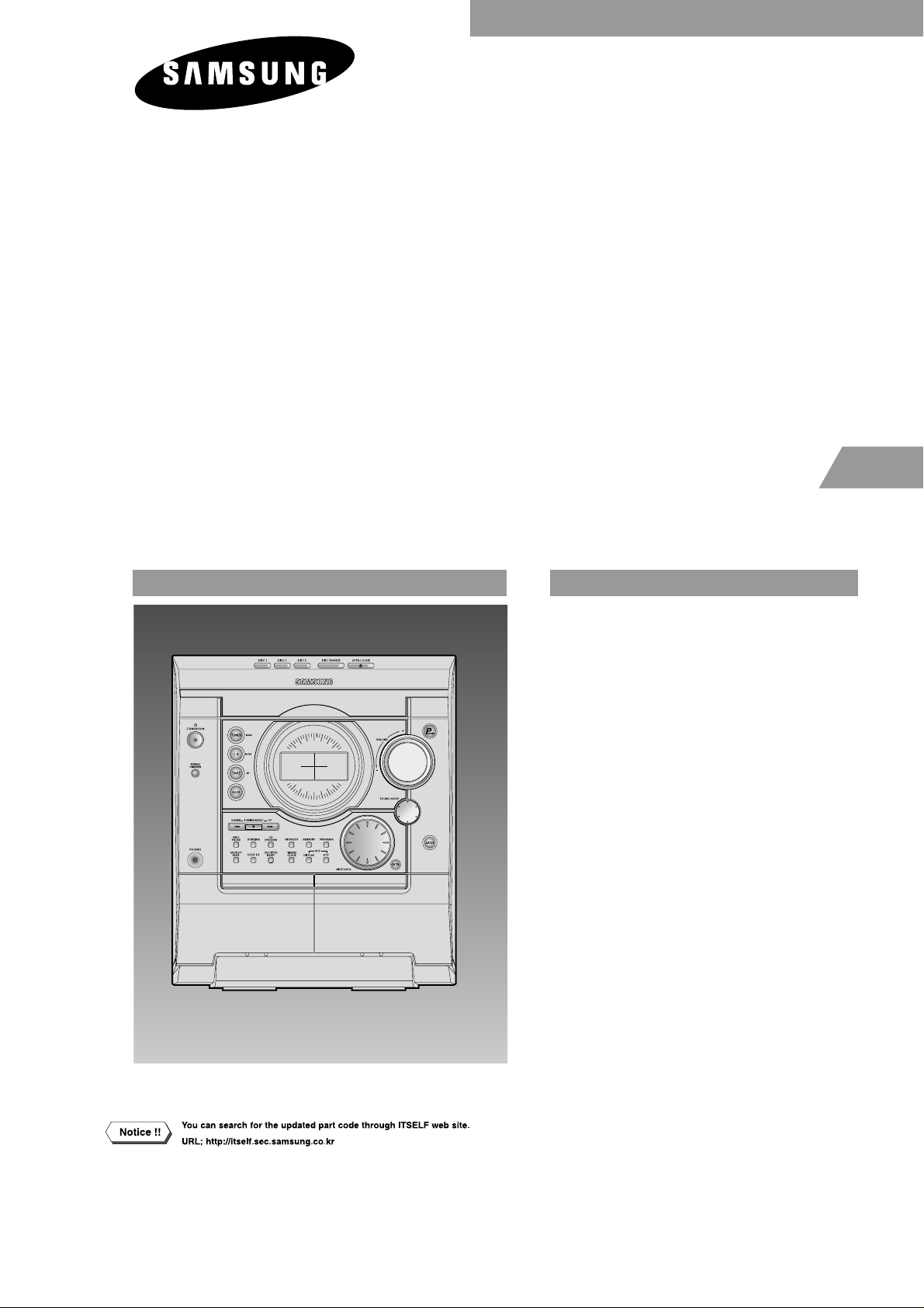
3 CD CHANGER
MINI MINI COMPONENT
MAX-ZJ550
SERVICE
Manual
MIMI MIMI COMPONENT SYSTEM CONTENTS
1. Alignment and Adjustments
2. Exploded Views and Parts List
3. Electrical Parts List
4. Block Diagrams
5. Wiring Diagram
6. Schematic Diagrams
- Confidential -

© Samsung Electronics Co.,Ltd. FEB. 2004
Printed in Korea
Code no. AH68-01383U
1-1Samsung Electronics
1. Alignment and Adjustments
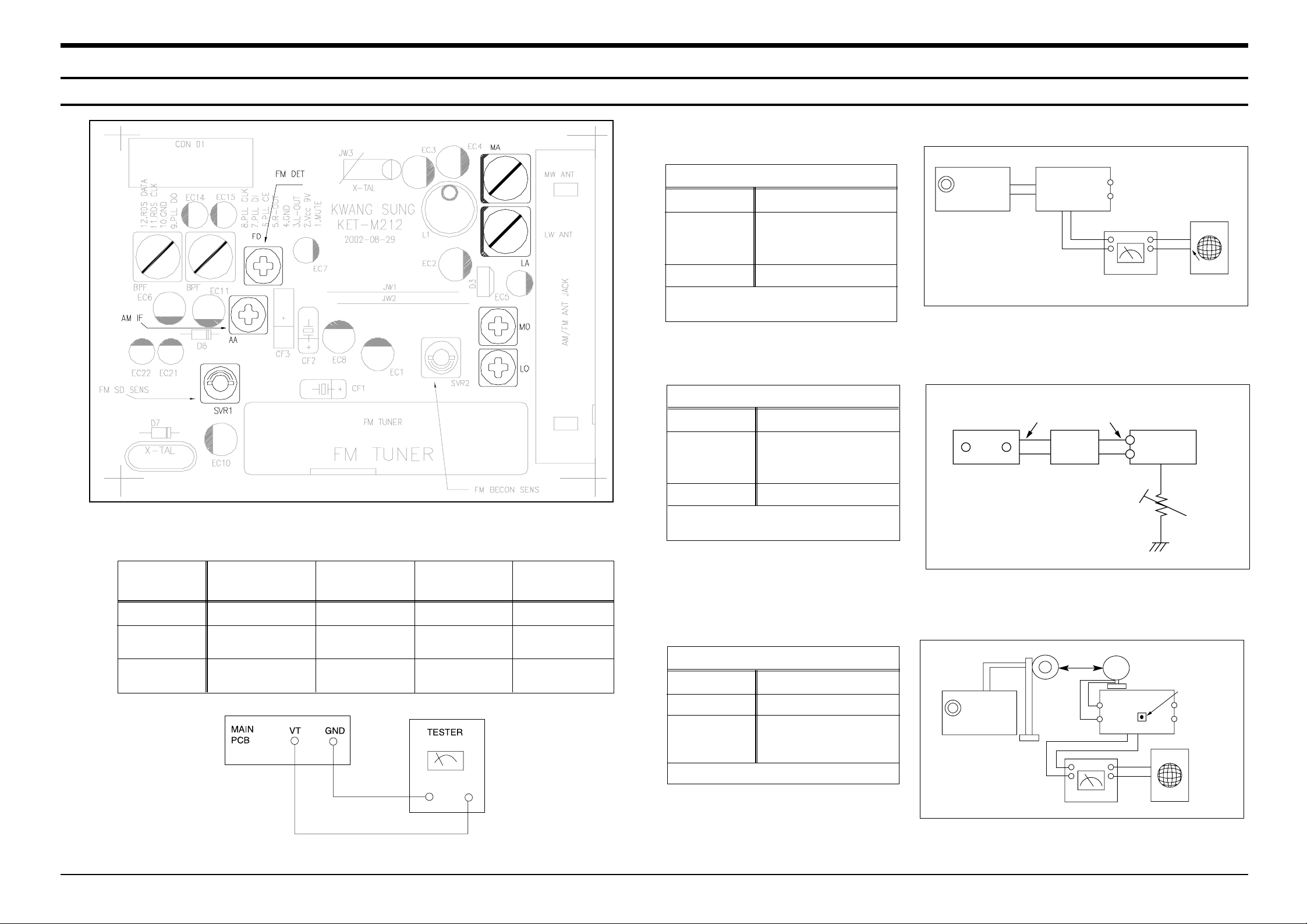
1-1.Tuner
FM THD Adjustment
Output
Output
28 dB(±2dB)
60 dB
Minumum Distortion (0.4% below)
(Figure 1-1)
SSG FREQ.
Adjustment
point
(FM DET)
98 MHz
FM DETECTOR COIL
FM Search Level Adjustment
Adjust SVR1 (Figure 1-2)
Figure1-2 FM Auto Search Level Adjustment
*Adjust FM S.S.G level to 28dB
Figure1-1 IF CENTER and THD Adjustment
SSG FREQ.
Adjustment
point
(SVR1)
98 MHz
BEACON
SENSITIVITY
SEMI-VR(10KΩ)
FM S.S. G
GND
28 dB
FM S.S. G
Output
GND
Speaker
Terminal
FM
Antenna
Terminal
Distortion Meter
Input
SET
Input
output
Oscilloscope
FM IN
FM Antenna
SET
20 kΩ
OUTPUT
AM SSG
450KHZ
INPUT
AM ANT
IN
Speaker Terminal
60cm
AM IF
VTVM Oscilloscope
AM(MW) I.F Adjustment
Maximum output (Figure 1-3)
SSG FREQ.
Frequency
Adjustment
point
450 kHz
522 kHz
AM IF
Figure1-3 AM I.F Adjustment
OUTPUT
* Adjustment Location of Tuner PCB
Fig 1-4 OSC Voltage
AM(MW) OSC
Adjustment
Output
1~7.0±0.5V
Received FREQ.
Adjustment
point
522~1611 KHz
MO
AM(MW) RF
Adjustment
ITEAM
594 KHz
MA
Maximum
Output(Fig1-4)
LW OSC
Adjustment
146~290 KHz
LO
2~7.0±0.5V
LW RF
Adjustment
150 KHz
LA
Maximum
Output(Fig1-4)

Alignment and Adjustments
1-2 Samsung Electronics
1-1-2 AM(MW),LW,SW1,SW2 Adjustment
Circuit Measuring Instrument & Step S.S.G Radio dial Adjusting Adjust for
to be Arrangement Frequency Setting Point
Adjusted
1 522KHz 522KHz MW OSC Adjust for
1.0V±0.1V at the low.
OSC Connect AM signal (IR117)
generator to loop
antenna,VTVM AND
oscilloscope 2 1611KHz 1611KHz MW OSC Check for 7.0V±1.0V at the high.
(Fig 1-3) (IR117)
AM
(MW)
RF “ 1 594KHz 594KHz MW ANT Maximum out
INTER FREQ “ 1 455KHz 522KHz TL2 Maximum out
OSC Fig 1-3 1 146KHz LW OSC Adjust for 2.0V±0.1V at the low.
LW 2 290KHz LW OSC Check for 7.0V±1.0V at the high.
RF 1 150KHz 150KHz LW ANT Maximum out
OSC Fig 1-3 1 2.3MHz SW1 OSC Adjust for
1.0V±0.1V at the low.
SW1 2 7.3MHz - Check for 8.5V±1.0V at the high.
RF 1 3.5MHz 3.5MHz SW1 ANT Maximum out
OSC Fig 1-3 1 9.5MHz SW2 OSC Adjust for 1.5V±0.1V at the low.
SW2 2 26.1MHz - Check for 8.0V±1.0V at the high.
RF 1 10MHz 10MHz SW2 ANT Maximum out
Alignment and Adjustments
1-3Samsung Electronics
(GND)
VTVM
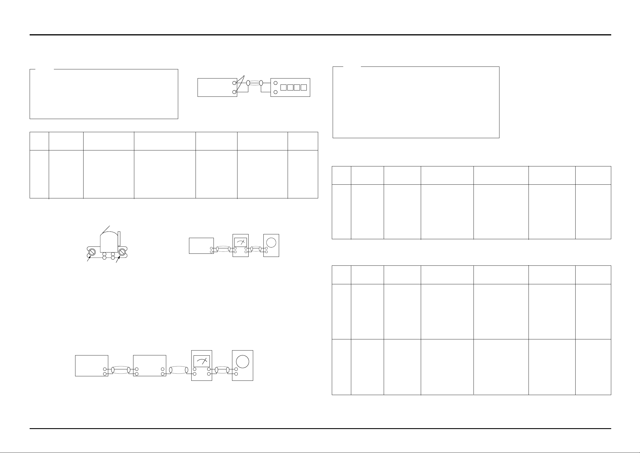
2-1. To Adjust Tape Speed
1) Measuring tape: i) MTT-111 (or equivalent)
(Tapes recorded with 3kHz)
ii) MTT-5512 (or equivalent)
2) Connect the SPK OUT of the MAIN PCB to the fre-
quency counter as in figure 1-5.
1) Before the actual adjustment, clean the play/recording
head.
2) Measuring tape :
i) MTT-114N(or equivalent 10kHz AZIMUTH control)
ii) MTT-5512
3) The cassette deck is connections as shown in figure 1-7.
Notes
Notes
NOR
SPEED
Control
1
SPK OUT
(connected
to the frequency
counter)
Turn VSR1 to
left and right
(FRONT PCB)
3KHz
Remark
Standard
To Adjust
Pre-Setup
Item
Step
Pre-Setup
Condition
1) Deck 1:MTT-111
2) Press PLAY
SW button
3) Deck 2:Same
as above
AZIMUTH
1
SPK OUT
(VTVM is
connected to
the scope)
- Turn the control
screw to as shown
in Figure 1-6.
Max output
and same phase
(both channels)
After
adjustment
secure it with
REGION
LOCK.
Remark
Standard
To Adjust
Pre-Setup
Item
Step
Pre-Setup
Condition
After putting MTT114N into Deck 1
- Press FWD PLA Y
button.
1
2
- Turn the control
screw to as shown in
Figure 1-6.
MAX OUTPUT
and same phase
(both channels)
CHECK TO
7mV(±0.5mV)
Remark
Standard
To Adjust
Pre-Setup
Item
Step
Pre-Setup
Condition
After putting MTT5512 into Deck 2
1) Press REC PLA Y button.
2) TAPE PCB JCW3 ,connected
to VTVM
Recording
Bias
Voltage
2-2. To Adjust PlayBack Level/REC
2. Adjust Deck 2 Play Level/ REC BIAS
1. Adjust Deck 1 Play Level
MAIN PCB
output
SPK OUT
Frequency Counter
Figure 1-5
SPK OUT
Figure 1-7
In Out
MAIN PCB
Oscilloscope
2. Cassette Deck
±1%
range
Figure 1-8
Audio OSC.
SET
(MAIN PCB)
Oscilloscope
AUX IN
VTVM
IN
SPK OUT
IN OUT
TP
AZIMUTH
Figure 1-6
Recording /Play head
AZIMUTH control screw
(RVS Play)
AZIMUTH control screw
(FWD Play)
SPK OUT
(VTVM is connected to the
scope)
Fig 1-8
- Turn JSR2L,JSR2R
to the right and left
After adjustment secure
it with
REGION
LOCK.
After putting MTT114N into Deck 2
- Press FWD PLA Y
button.
Samsung Electronics2-1
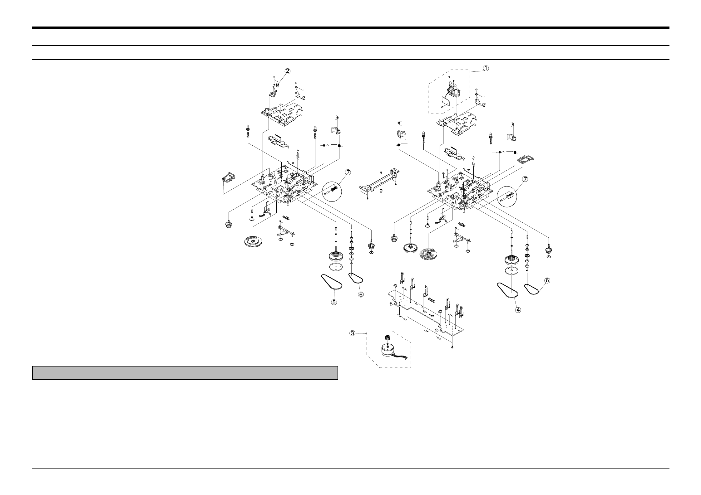
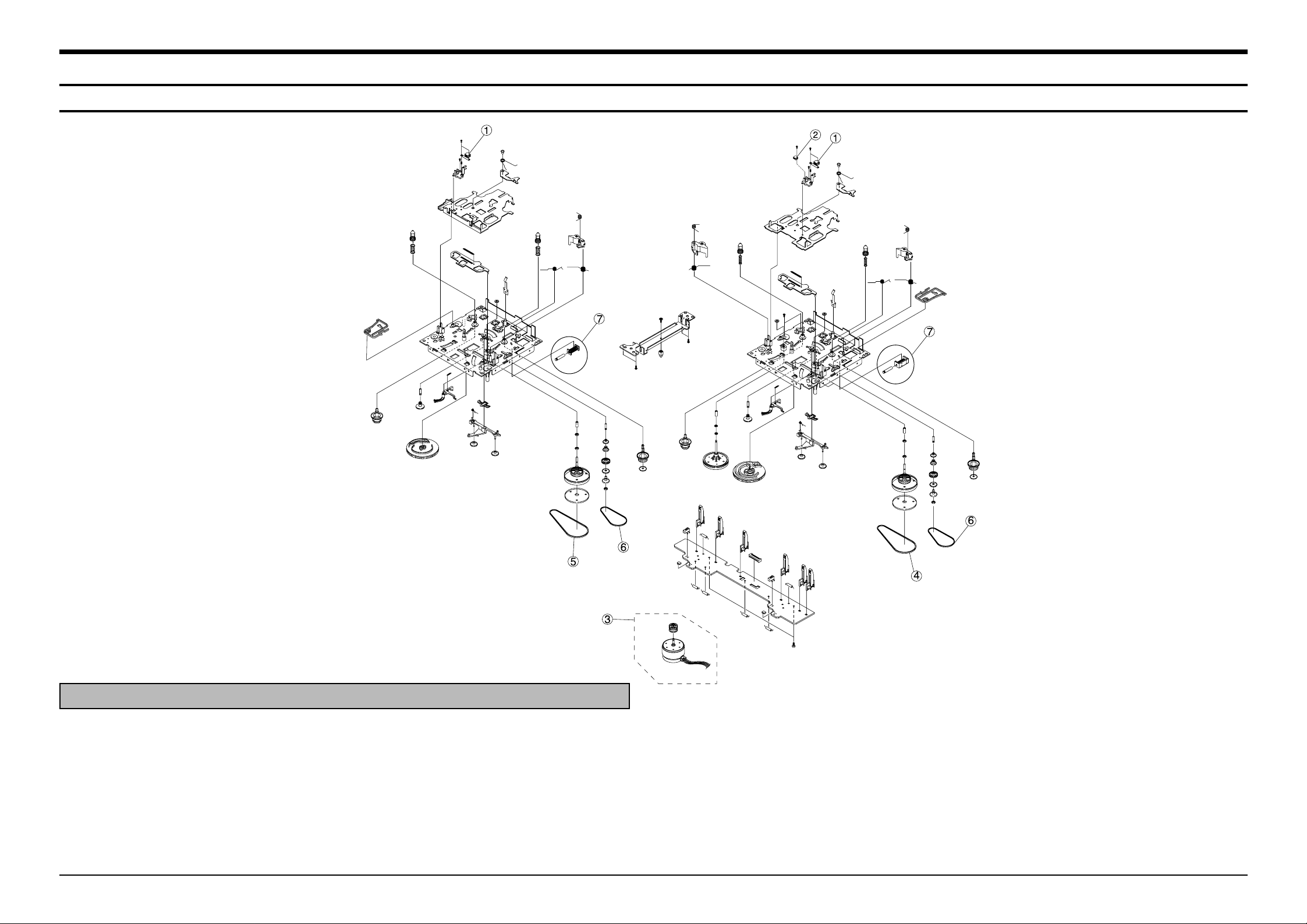
2.Exploded Views and Par ts List
2-1 Cassette Deck :ADR268FTW(OPTION)
No. Code No. Description Specification Remarks
AH59-01145A DECK-CASSETTE ADR268FTW
1 AH81-00368A ASS.Y RP HEAD ADR2400-RP(SANKYO) MT91-11010T
2 AH81-00141B HEAD PB MK10P-SS2N3 MT59-00041V
3 AH81-00363A ASS,Y MOTOR ADR2400-SHU2L MT91-15012J
4 AH81-00364A BELT MAIN1 ADR2400-MAIN 0.5 6602-001056
5 AH81-00365A BELT MAIN2 ADR2400-MAIN 1.25 6602-001010
6 AH81-00101A BELT SUB ADR2400-FR 6602-001055
7 AH81-00102A SOLENOID ADR2400-1(20
Ω)
MT75-00049A
Samsung Electronics
2-2
2.Exploded Views and Par ts List
2-2 Cassette Deck :ADR268DSW1-1(Option)
No. Code No. Description Specification Remarks
AH59-01144A DECK-CASSETTE ADR268DSW1-1
1 AH81-01031A HEAD 1WAY T21V1CAA MT59-K0015A
2 AH81-01032A HEAD ERASE DZLE15B-C1 MT59-K0009A
3 AH81-00363A ASS,Y MOTOR ADR2400-SHU2L MT91-15012J
4 AH81-00364A BELT MAIN1 ADR2400-MAIN 0.5 6602-001056
5 AH81-00365A BELT MAIN2 ADR2400-MAIN 1.25 6602-001010
6 AH81-00101A BELT SUB ADR2400-FR 6602-001055
7 AH81-00102A SOLENOID ADR2400-1(20
Ω)
MT75-00049A
 Loading...