

Samsung MAX-X55 Service Manual
MINI COMPONENT
SYSTEM
BASIC MODEL: MAX-X55/X56/X57
MAX-X65/X66
SERVICE
Manual
MINI COMPONENT SYSTEM Features
* CD/MP3-CD/CD-R/RW Playback
* Tuner
* Tape Deck
- Confidential -

ELECTRONICS
Ch4 Troubleshooting
1. MAIN(MAX-X55) 4-1
2. MAIN(MAX-X56) 4-2
3. DISC PLAY 4-3
Ch2 Product Descriptions
1. Notes on Discs 2-1
2. Specifications 2-2
3. Accessories 2-3
4. Specification comparison 2-4
Ch1 Precautions
1-1. Safety Precautions 1-1
1-2. Servicing Precautions 1-2
1-3. Precautions for Electrostatically
Sensitive Device (ESDs) 1-3
1-4. Special Precations and Waring
Lables for Laser Products 1-4
1-5. Special Precautions for HDD 1-5
INDEX
Ch3 How to disassemble
How to disassemble 3-1
Ch5 Exploded View & Parts List
1-1. Total Exploded View 5-1
1-2. Parts List of Exploded View 5-2
2. Electrical Parts List 5-3
Ch6 Wiring &PCB Diagram
1.Wiring Diagram 6-1
2-1. MAIN PCB (MAX-X55) 6-2
2-2. MAIN PCB (MAX-X56/DX56) 6-3
2-3. FRONT PCB 6-4
Ch7 Schematic Diagram
1.Block Diagram 7-1
2-1. MAIN (MAX-X55-1) 7-2
2-2. MAIN (MAX-X55-2) 7-3
2-3. MAIN (MAX-X56-1) 7-4
2-4. MAIN (MAX-X56-2) 7-5
2-5. FRONT-1 7-6
2-6. FRONT-2 7-7
2-7. AMP 7-7
1. Precautions
Follow these safety, servicing and ESD precautions to prevent damage and protect against potential hazards
such as electrical shock and X-rays.
Samsung Electronics 1-1
1-1 Safety Precautions
1. Be sure that all of the built-in protective
devices are replaced.
2. When reinstalling the chassis and its
assemblies, be sure to restore all protective
devices, including control knobs and
compartment covers.
3. Make sure that there are no cabinet
openings through which people-particularly children--might insert fingers
and contact dangerous voltages. Such
openings include the spacing between the
picture tube and the cabinet mask,
excessively wide cabinet ventilation slots,
and improperly fitted back covers.
4. Design Alteration Warning:
Never alter or add to the mechanical or
electrical design of the unit. Example: Do
not add auxiliary audio or video connectors. Such alterations might create a safety
hazard. Also, any design changes or additions will void the manufacturer's warranty.
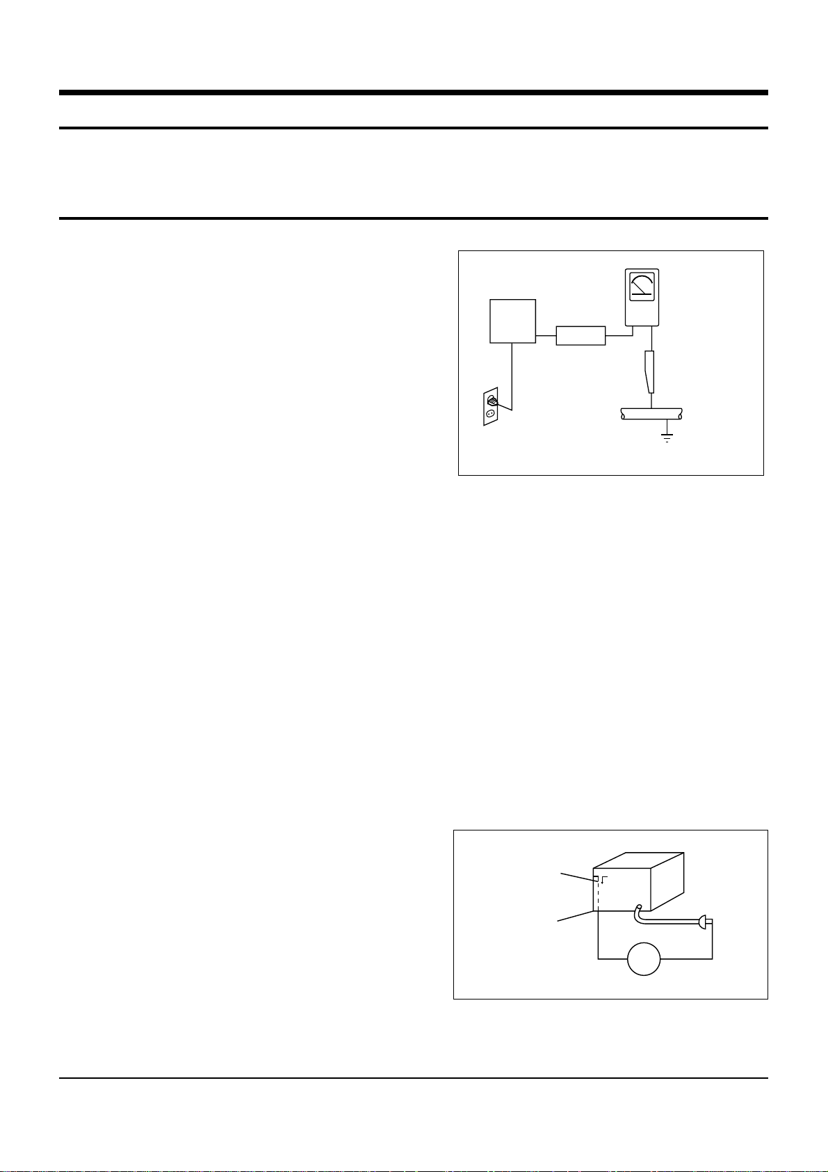
5. Leakage Current Hot Check (Figure 1-1):
Warning: Do not use an isolation
transformer during this test. Use a leakagecurrent tester or a metering system that
complies with American National Standards
Institute (ANSI C101.1, Leakage Current for
Appliances), and Underwriters Laboratories
(UL Publication UL1410, 59.7).
With the unit completely reassembled, plug
the AC line cord directly into a 120V AC
outlet. With the unit's AC switch first in
the ON position and then OFF, measure the
current between a known earth ground
(metal water pipe, etc.) and all exposed
metal parts. Examples: Handle brackets,
metal cabinets, screwheads and control
shafts. The current measured should not
exceed 0.5 milliamp. Reverse the powerplug prongs in the AC outlet and repeat.
6. Insulation Resistance Cold Check:
(1) With the unit's AC plug disconnected
from the AC source, connect an electrical
jumper across the two AC prongs. (2) Set
the power switch to ON. (3) Measure the
resistance between the shorted AC plug and
any exposed metallic parts. Example:
Screwheads, antenna, control shafts or
handle brackets.
If any of the exposed metallic parts has a
return path to the chassis, the measured
resistance should be between 1 and 5.2
megohms. If there is no return path, the
measured resistance should be "infinite." If
the resistance is outside these limits, a shock
hazard might exist. See Figure 1-2
Fig. 1-1 AC Leakage Test
Fig. 1-2 Insulation Resistance Test
(Reading should
not be above
Device
Under
Test
Test all
exposed metal
surfaces
2-Wire Cord
Also test with
plug reversed
(using AC adapter
plug as required)
0.5mA)
Leakage
Currant
Tester
Earth
Ground
Antenna
Terminal
Exposed
Metal Part
ohm
Ohmmeter

Samsung Electronics1-2
1-1 Safety Precautions (Continued)
7. Components, parts and wiring that appear
to have overheated or that are otherwise
damaged should be replaced with parts
that meet the original specifications.
Always determine the cause of damage or
overheating, and correct any potential
hazards
8. Observe the original lead dress, especially
near the following areas: Antenna
wiring, sharp edges, and especially the
AC and high voltage power supplies.
Always inspect for pinched, out-of-place,
or frayed wiring. Do not change the
spacing between components and the
printed circuit board. Check the AC
power cord for damage. Make sure that
no wires or components touch thermally
hot parts.
9. Product Safety Notice:
Some electrical and mechanical parts
have special safety-related characteristics
which might not be obvious from visual
inspection. These safety features and the
protection they give might be lost if the
replacement component differs from the
original--even if the replacement is rated
for higher voltage, wattage, etc.
10 Components that are critical for safety are
indicated in the circuit diagram by
shading, or . Use replacement
components that have the same ratings,
especially for flame resistance and
dielectric strength specifications. A
replacement part that does not have the
same safety characteristics as the original
might create shock, fire or other hazards.
1-2 Servicing Precautions
1. Servicing precautions are printed on the
cabinet. Follow them.
2. Always unplug the unit's AC power cord
from the AC power source before
attempting to: (a) Remove or reinstall any
component or assembly, (b) Disconnect an
electrical plug or connector, (c) Connect a
test component in parallel with an
electrolytic capacitor.
3. Some components are raised above the
printed circuit board for safety. An
insulation tube or tape is sometimes used.
The internal wiring may be clamped to
prevent contact with thermally hot
components. Reinstall all such elements to
their original position.
4. After servicing, always check that the
screws, components and wiring have been
correctly reinstalled. Make sure that the
portion around the serviced part has not
been damaged.
5. Check the insulation between the blades of
the AC plug and accessible conductive parts
(examples: metal panels, input terminals
and earphone jacks).
6. Insulation Checking Procedure: Disconnect
the power cord from the AC source and
turn the power switch ON. Connect an
insulation resistance meter (500V) to the
blades of the AC plug.
The insulation resistance between each
blade of the AC plug and accessible
conductive parts (see above) should be
greater than 1 megohm.
7. Never defeat any of the B+ voltage
interlocks. Do not apply AC power to the
unit (or any of its assemblies) unless all
solid-state heat sinks are correctly installed.
8. Always connect a test instrument's ground
lead to the instrument chassis ground
before connecting the positive lead; always
remove the instrument's ground lead last.
Precautions
Warning1: First read the "Safety Precautions" section of this manual. If some unforeseen circumstance creates a conflict
between the servicing and safety precautions, always follow the safety precautions.
Samsung Electronics 1-3
1-3 Precautions for Electrostatically Sensitive Devices (ESDs)
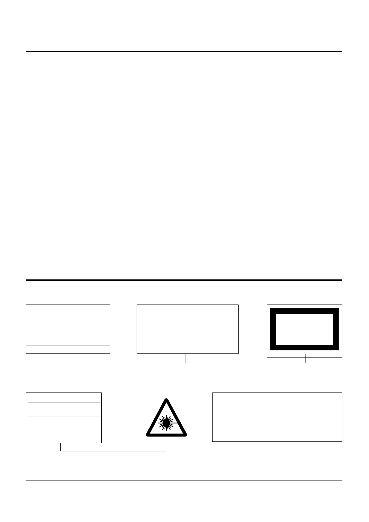
1-4 Special Precautions and Warning Labels for Laser Products
1. Some semiconductor ("solid state") devices
are easily damaged by static electricity.
Such components are called Electrostatically
Sensitive Devices (ESDs). Examples include
integrated circuits and some field-effect
transistors. The following techniques will
reduce the occurrence of component
damage caused by static electricity.
2. Immediately before handling any
semiconductor components or assemblies,
drain the electrostatic charge from your
body by touching a known earth ground.
Alternatively, wear a discharging
wrist-strap device. (Be sure to remove it
prior to applying power--this is an electric
shock precaution.)
3. After removing an ESD-equipped assembly,
place it on a conductive surface such as
aluminum foil to prevent accumulation of
electrostatic charge.
4. Do not use freon-propelled chemicals.
These can generate electrical charges that
damage ESDs.
5. Use only a grounded-tip soldering iron
when soldering or unsoldering ESDs.
6. Use only an anti-static solder removal
device. Many solder removal devices are
not rated as "anti-static" (these can
accumulate sufficient electrical charge to
damage ESDs).
7. Do not remove a replacement ESD from its
protective package until you are ready to
install it. Most replacement ESDs are
packaged with leads that are electrically
shorted together by conductive foam,
aluminum foil or other conductive
materials.
8. Immediately before removing the protective
material from the leads of a replacement
ESD, touch the protective material to the
chassis or circuit assembly into which the
device will be installed.
9. Minimize body motions when handing
unpackaged replacement ESDs. Motions
such as brushing clothes together, or lifting
a foot from a carpeted floor can generate
enough static electricity to damage an ESD.
Precautions
UL : Manufactured for U.S.A. Market.
CSA : Manufactured for Canadian Market.
EU : Manufactured for European Market.
SCAN : Manufactured for Scandinavian
Market.
This Product Complies with
DHHS Rules 21CFR, Sub
chapter J.At date of Manufacture
(UL)
(UL,CSA,SCAN)
(EU)
CERTIFIED ONLY TO CANADIAN
ELECTRICAL CODE.
CERTIFIE EN VERTU DU CODE
CANADIAN DE LELETRICITE
SEULEMENT
(CSA)
CLASS 1
LASER PRODUCT
(UL,CSA,EU)
Fig. 1-3 Warning Labels (Location: Enclosure Block)
Fig. 1-4 Warning Labels (Location: Disc Clamper, Inner Side of Unit Door or Nearby Unit Chassis )
CAUTION : INVISIBLE LASER RADIATION WHEN OPEN
AND INTERLOCKS DEFEATEO AVOIDEXPOSURE TO BEAM
ADVARSEL:USYNLIG LASERSTRÅLING VED ABNING
NÅR SIKKERHEDSAFBRYDERE ER UDE AF FUNKTION
UNDGA UDSAETTELSE FOR STRALING
VARO:AVATTAESSA JA SUOJALUKITUS OHITETTAESSA
OLET ALTTINA NAKYMATTÖMALLE LASERSATEILYLLE ALA
KATSO SATEESEEN!
VARNING:OSYNLIG LASERSTRÅLNING NAR DENNA DEL
AR OPPNAD OCH SPARREN AR URKOPPLAD BETRAKTA
EJSTRÅLEN!
Samsung Electronics1-4
1-4 Special Precautions and Warning Labels for Laser Products (Continued)
1-4-1 Warnings
1. When servicing, do not approach the LASER
exit with the eye too closely. In case it is
necessary to confirm LASER beam emission,
be sure to observe from a distance of more
than 30 cm from the surface of the objective
lens on the optical pick-up block.
2. Do not attempt to handle the objective lens
when the DISC is not on the tray.
1-4-2 Laser Diode Specifications
Material: GaAs+ GaAlAs
Wavelength: 760-800 nm
Emission Duration: Continuous
Laser Output: 0.2 mw (measured at a
1.6 mm distance from the objective lens
surface on the optical pick-up block.)
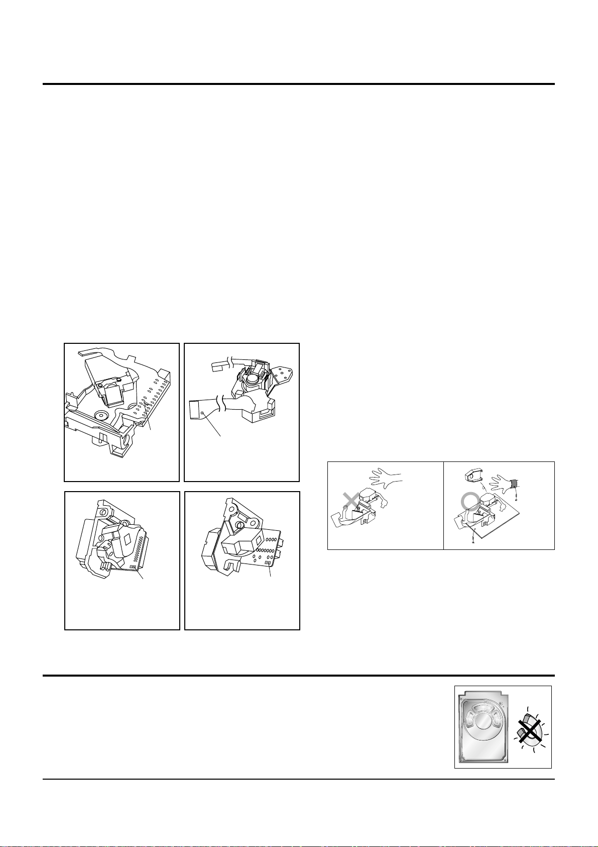
1-4-3 Handling the Optical Pick-up
1. Static electricity from clothing or the body
may cause electrostatic breakdown of the
laser diode in the Optical Pickup. Follow
this procedure:
2. Place a conductive sheet on the work bench
(i.e., the black sheet used for wrapping
repair parts.) Note: The surface of the work
bench should be covered by a copper
ground plane, which is grounded.
3. The repair technician must wear a wrist
strap which is grounded to the copper sheet.
4. To remove the Optical Pickup block:
Place the set on the conductive sheet, and
momentarily touch the conductive sheet
with both hands. (While working, do not
allow any electrostatic sources--such as
clothes--to touch the unit.)
5. Ground the "Short Terminal" (located on the
PCB, inside the Pickup Assembly) before
replacing the Pickup. This terminal should
be shorted whenever the Pickup Assembly
is lifted or moved.
6. After replacing the Pickup, reopen the Short
Terminal. See diagrams below:
Precautions
1-5 Special Precautions for HDD
* HDD Data Maintenance Step
1. Since the data on the HDD is weak to mechanical shock, place the HDD in a safe
location that is free from mechanical shock once it is removed from the main unit.
2. In order to safe keep the data on the HDD, back up the data before the repair or
make sure not to place the HDD near any electrical appliance that generates a strong
magnetic field.
short
terminal
SOH91VI(LDP)
short terminal
SOH91CI(CAR,walkman)
THE UNIT
(1) WRIST-STRAP
FOR GROUNDING
short
terminal
SOH-A1
(CMS-V10,CMS-V30)
SOH94T4N
(CMS-V10,CMS-V30)
short
terminal
1M
1M
CONDUCTIVE SHEET

Samsung Electronics 2-1
2-1. Product Description
1. Notes on discs
CD-R Discs
•
Some CD-R discs may not be playable depending on the disc recording device (CD-Recorder or PC) and the
condition of the disc.
•
Use a 650MB/74 minute CD-R disc.
Do not use CD-R disk over 700MB/80 minute as much as possible since it may not be played back.
•
Some CD-RW (Rewritable) media, may not be playable.
•
Only CD-Rs that are properly "closed" can be fully played. If the session is closed but the disc is left open, you
may not be able to fully play the disc.
CD-R JPEG Discs
•
Only files with the ".jpeg" and ".JPEG" extensions can be played.
•
If the disc is not closed, it will take longer to start playing and not all of the recorded files may be played.
•
Only CD-R discs with JPEG files in ISO 9660 or Joliet format can be played.
•
JPEG file names should be 8 characters or less in length and contain no blank spaces or special characters (. / = +).
•
Only a consecutively written multisession disc can be played. If there is a blank segment in the multisession disc, the
disc can be played only up to the blank segment.
•
A maximum of 9,999 images can be stored on a single CD.
•
When playing a Kodak/Fuji Picture CD, only the JPEG files in the picture folder can be played.
•
Picture discs other than Kodak/Fuji Picture CDs may take longer to start playing or may not play at all.
Disc Recording Format
CD-R MP3 Discs
•
Only CD-R discs with MP3 files in ISO 9660 or Joliet format can be played.
•
MP3 file names should be 8 characters or less in length and contain no blank spaces or special characters (. / = +).
•
Use discs recorded with a compression/decompression data rate greater than 128Kbps.
•
Only files with the ".mp3" and ".MP3" extensions can be played.
•
Only a consecutively written Multisession disc can be played. If there is a blank segment in the Multisession disc,
the disc can be played only up to the blank segment.
•
If the disc is not closed, it will take longer to begin playback and not all of the recorded files may be played.
•
For files encoded in Variable Bit Rate (VBR) format, i.e. files encoded in both low bit rate and high bit rate
(e.g., 32Kbps ~ 320Kbps), the sound may skip during playback.
•
A maximum of 500 tracks can be played per CD.
•
A maximum of 300 folders can be played per CD.

2-2 Samsung Electronics
2. Specifications
RADIO
AM (MW)
Signal/noise ratio 40 dB
Usable sensitivity 54 dB
Total harmonic distortion 2 %
FM
Signal/noise ratio 62 dB
Usable sensitivity 10 dB
Total harmonic distortion 0.3 %
COMPACT DISC PLAYER
Capacity 3 discs
Frequency range 20 Hz - 20 KHz (± 1 dB)
Signal/noise ratio 90 dB (at 1 KHz) with filter
Distortion 0.05 % (at 1 KHz)
Channel separation 74 dB
Disc sizes Diameter: 120 or 80 mm. Thickness: 1.2 mm
TAPE DECK
Frequency range 125 Hz ~ 8 KHz
Signal/noise ratio 40 dB
Channel separation 35 dB
Erasing effect 50 dB
AMPLIFIER
Output power
Front Speaker (6 Ω)(MAX-X55) 40 Watts/CH RMS,IEC (total harmonic distortion: 10 %)
Front Speaker (6 Ω)(MAX-X56) 80 Watts/CH RMS,IEC (total harmonic distortion: 10 %)
Front Speaker (6 Ω)(MAX-X57) 90 Watts/CH RMS,IEC (total harmonic distortion: 10 %)
Front Speaker (6 Ω)(MAX-X65)
150 Watts/CH RMS,IEC (total harmonic distortion: 10 %)
Front Speaker (6 Ω)(MAX-X66)
150 Watts/CH RMS,IEC (total harmonic distortion: 10 %)
Subwoofer Speaker (4 Ω)(MAX-X66)
150 Watts/CH RMS,IEC (total harmonic distortion: 10 %)
Channel separation 45 dB
Signal/noise ratio 75 dB
GENERAL
Power Consumption
85W(MAX-X55)
Power Consumption
65W(MAX-X56/X57)
Power Consumption
40W(MAX-X65/X66)
Dimensions 270 (W) x 317 (H) x 395 (D) mm
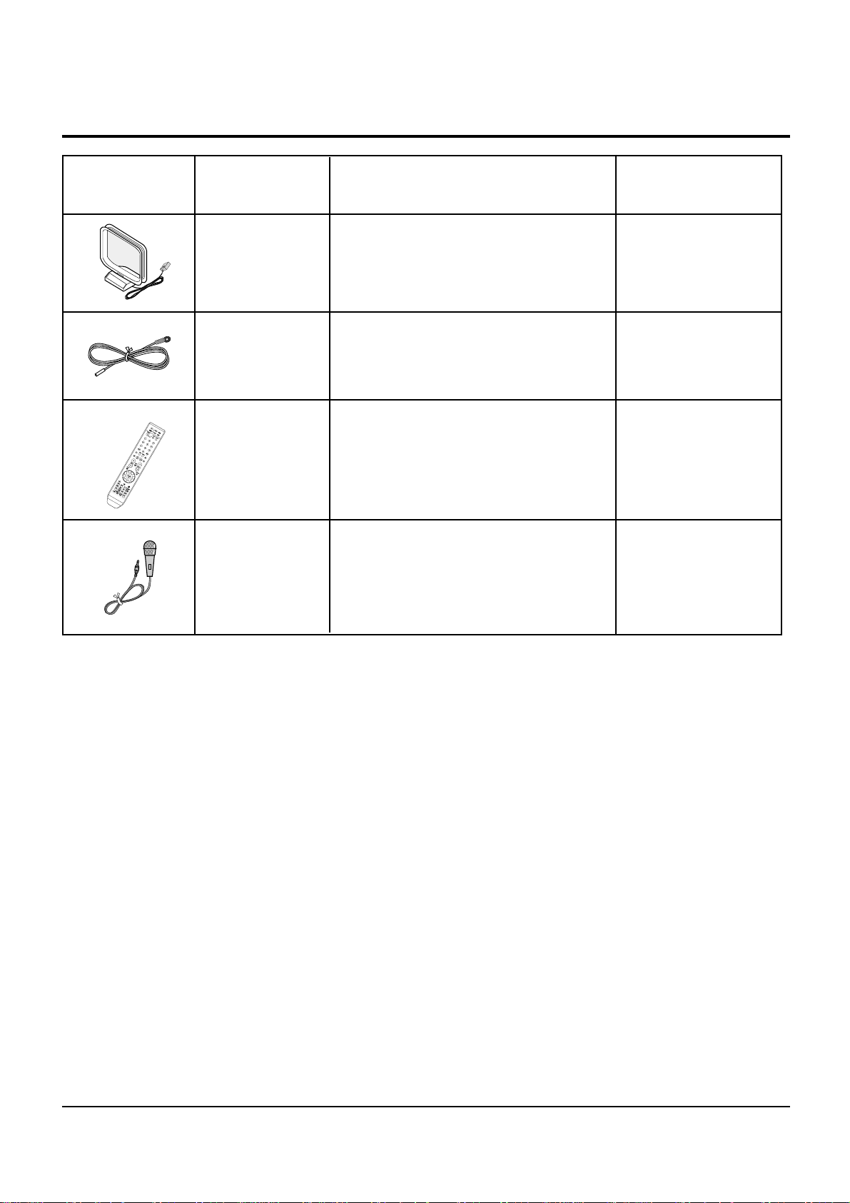
Picture Code no. Description & Specification Remarks
AH42-00023A
ANT LOOP-AM;-,MAX-DT55,-,-,1KHZ
AH42-00021A
ANT FM T;T18011F-1,75 ohm,1800mm
AH59-01696E REMOCON;MAX-X55/X56,NON-KOR
MAX-X55,X56,X57 EXP
AH59-01696F REMOCON;MAX-X65/X66,NON-KOR MAX-X65,X66 EXP
AH59-01696G REMOCON;MAX-X55/X56/X65/X66,KOR
MAX-X55,X66,X65 KOR
AH59-01695G REMOCON;MAX-DX55/DX56,NON-KOR MAX-DX55,DX56 EXP
AH59-01695H REMOCON;MAX-DX55/DX56,KOR
MAX-DX55 DX56 KOR
AH59-30001H MICROPHONE;YMC-2511,-,-,
MAX-X65/X66T/SMT
Samsung Electronics 2-3
3. Accessories
2-4 Samsung Electronics
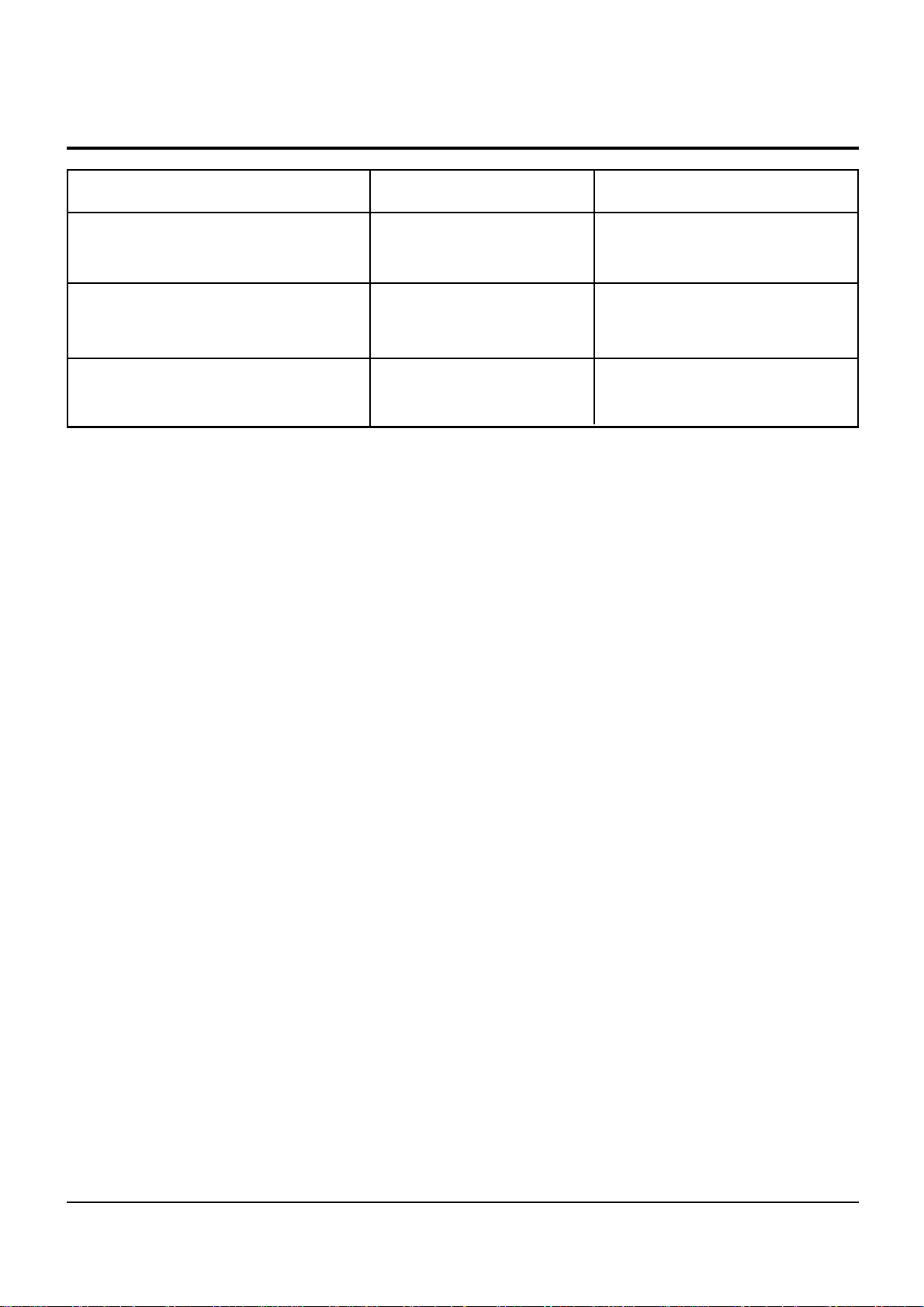
4. Specification Comparison
X55
Model Name
T55
2006
2007Year
70W
80W
2.1CH
2.0CHCH
OUTPUT
Samsung Electronics 3-1
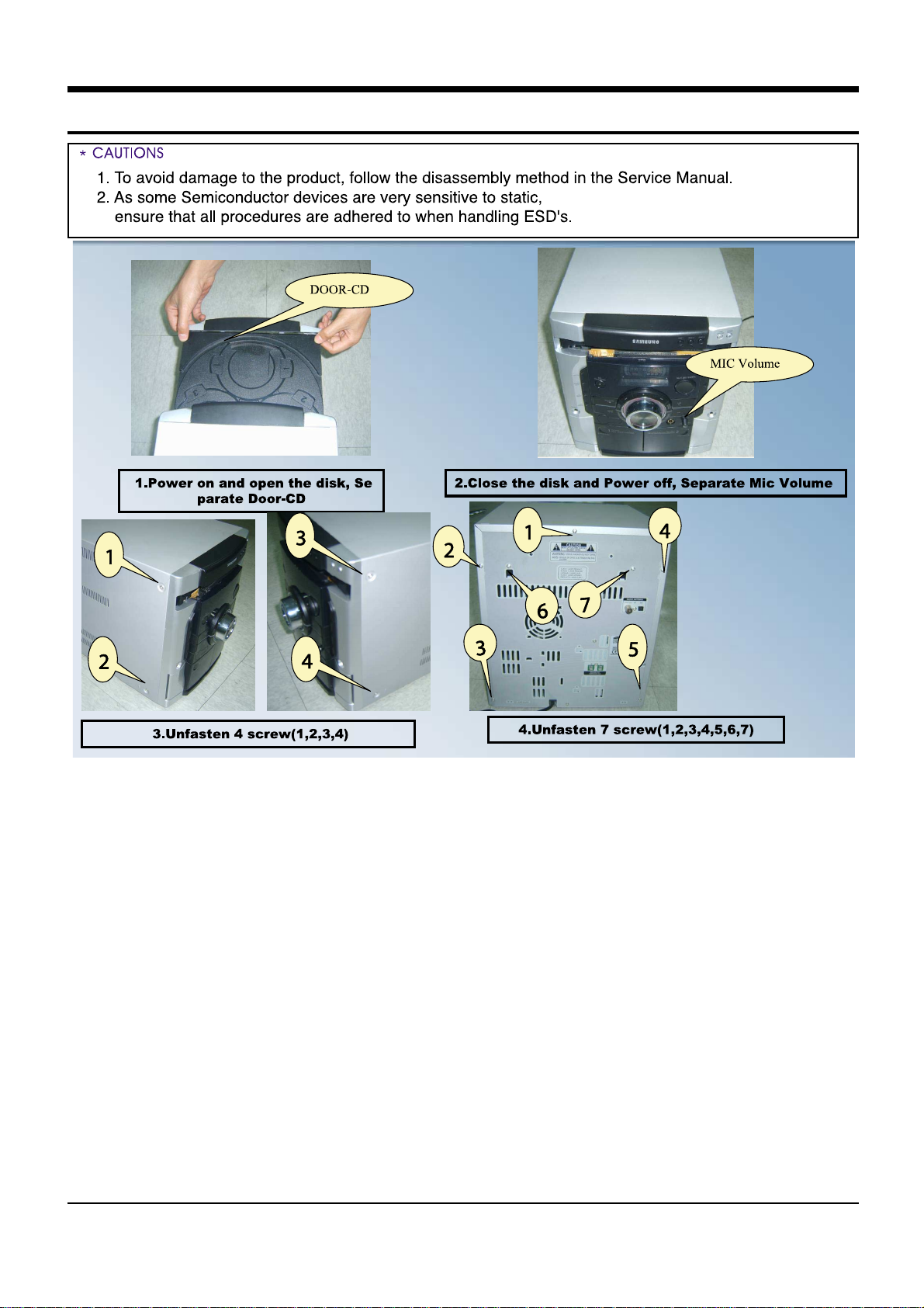
3. How to disassemble
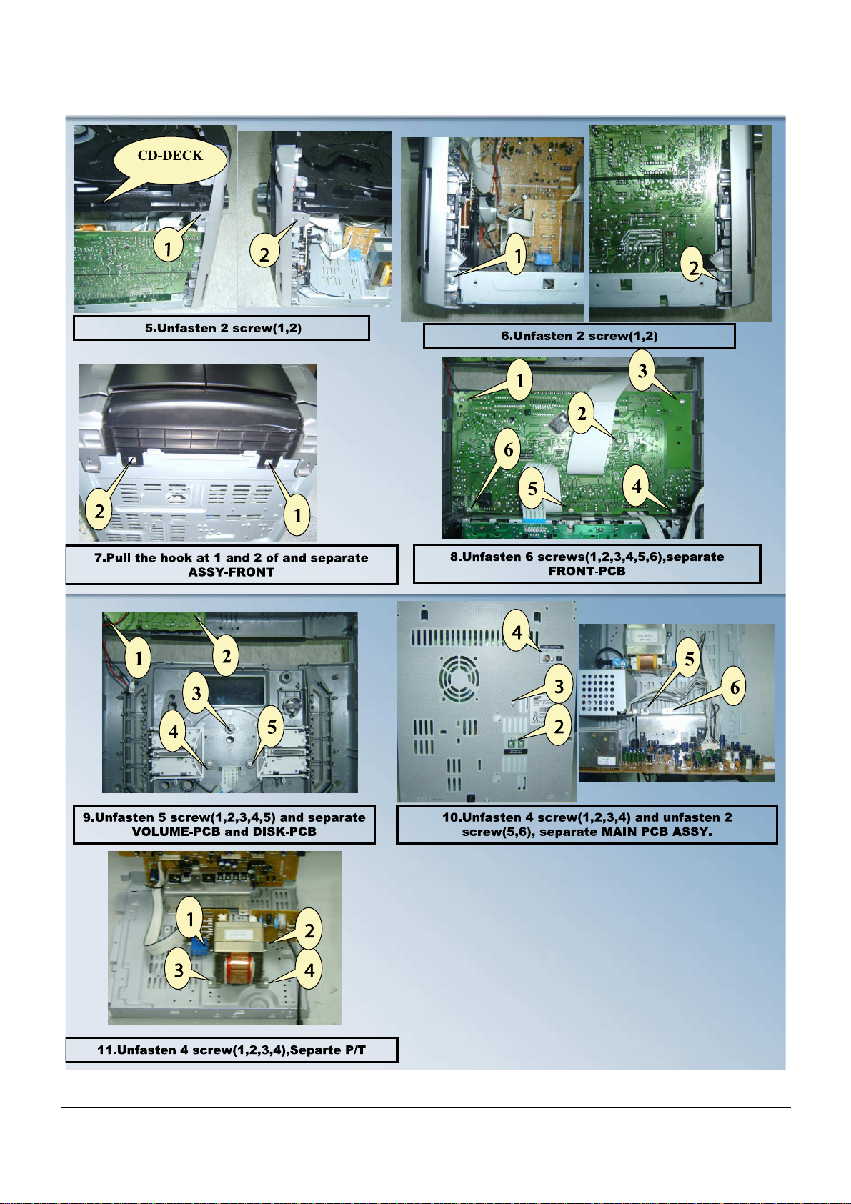
3-2 Samsung Electronics
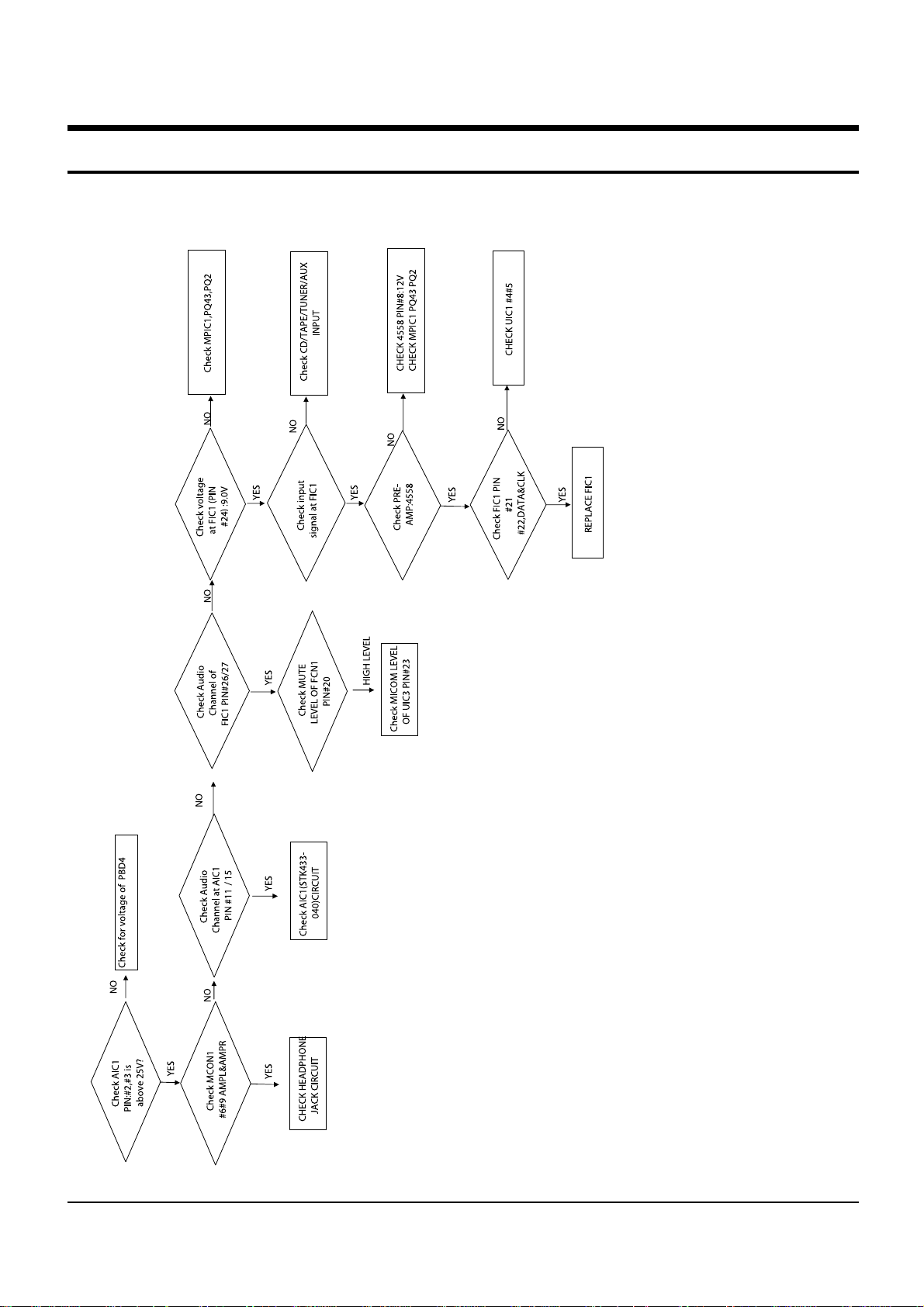
Samsung Electronics 4-1
4. TroubleShooting
MAIN (MAX-X55)
 Loading...