

SAMSUNG MAX-VL45 Service Manual
3 VCD CHANGER
MINI MINI COMPONENT
MAX-VL45
SERVICE
Manual
MIMI MIMI COMPONENT SYSTEM CONTENTS
1. Alignment and Adjustments
2. Exploded Views and Parts List
3. Electrical Parts List
4. Block Diagrams
5. PCB Diagrams
6. Wiring Diagram
7. Schematic Diagrams

ELECTRONICS
© Samsung Electronics Co.,Ltd. NOV. 2001
Printed in Korea
Code no. AH68-00664U
1-1Samsung Electronics
1. Alignment and Adjustments
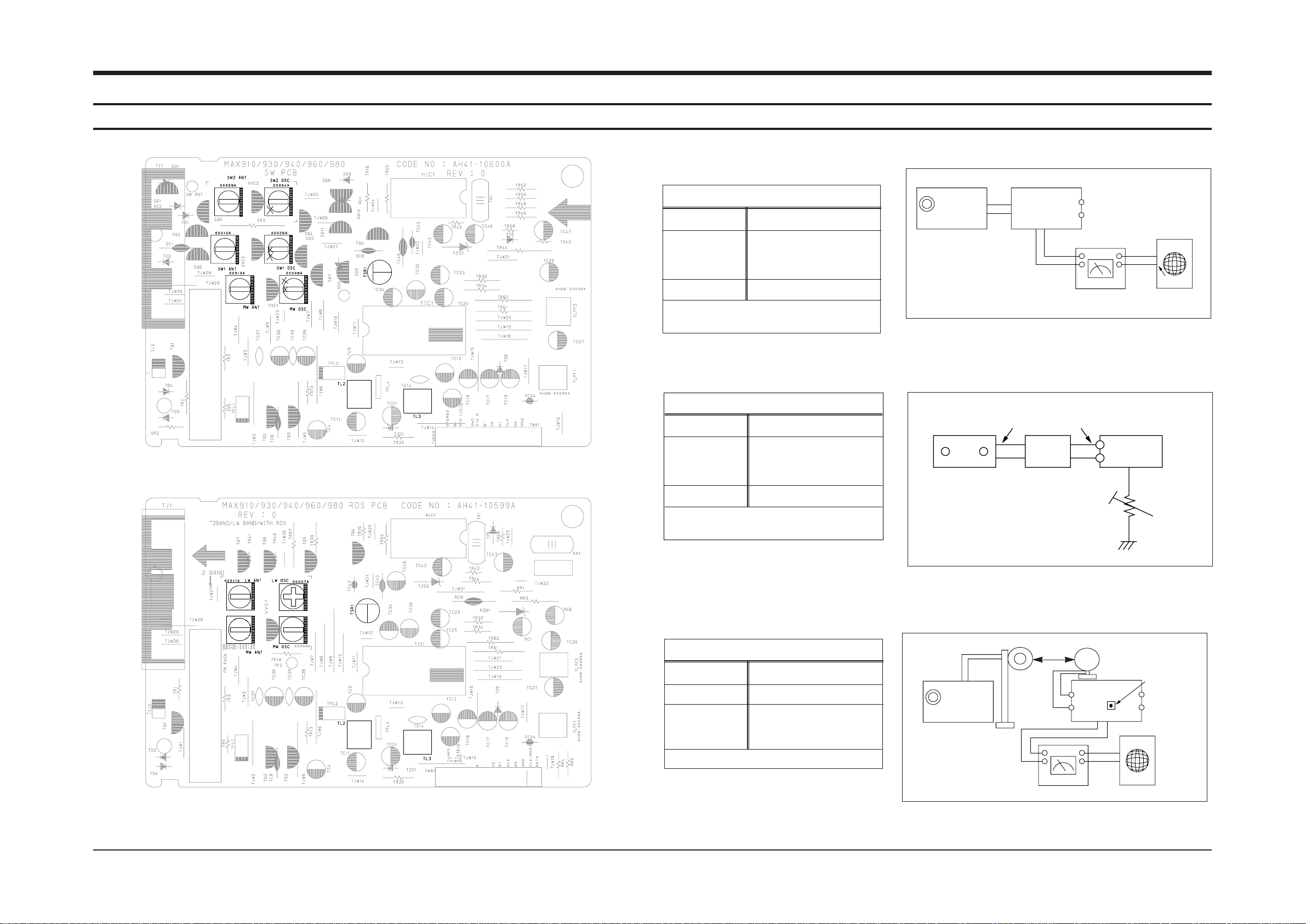
1-1 Tuner
FM THD Adjustment
Output
Output
23 dB
60 dB
Minumum Distortion (0.3% below)
(Figure 1-1)
SSG FREQ.
Adjustment
point
(TL3)
98 MHz
FM DETECTOR COIL
FM Search Level Adjustment
Adjust TSR1 so that “TUNED” of FLT
is lighted (Figure 1-2)
Figure1-2 FM Auto Search Level Adjustment
*Adjust FM S.S.G level to 23dB
Figure1-1 IF CENTER and THD Adjustment
SSG FREQ.
Adjustment
point
(TSR1)
98 MHz
BEACON
SENSITIVITY
SEMI-VR(5K½)
FM S.S.G
GND
23 dB
FM S.S.G
Output
GND
Speaker
Terminal
FM
Antenna
Terminal
Distortion Meter
Input
SET
Input
output
Oscilloscope
FM IN
FM Antenna
SET
5 k½
OUTPUT
AM SSG
450KHZ
INPUT
AM ANT
IN
Speaker Terminal
60cm
TL2
VTVM Oscilloscope
AM(MW) I.F Adjustment
Maximum output (Figure 1-3)
SSG FREQ.
Frequency
Adjustment
point
(TL2)
450 kHz
522 kHz
AM I.F COIL
Figure1-3 AM I.F Adjustment
OUTPUT
* Adjustment Location of SW Band
* Adjustment Location of LW Band

Alignment and Adjustments
1-2 Samsung Electronics
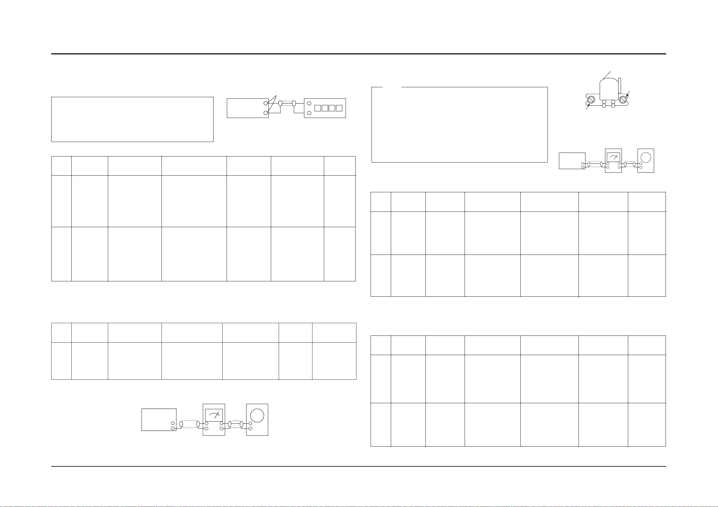
1-1-2 AM(MW),LW,SW1,SW2 Adjustment
Circuit Measuring Instrument & Step S.S.G Radio dial Adjusting Adjust for
to be Arrangement Frequency Setting Point
Adjusted
1 522KHz 522KHz MW OSC Aduust for 1.0V±0.1V at the low.
OSC Connect AM signal (IR117)
generator to loop
antenna,VTVM AND
oscilloscope 2 1611KHz 1611KHz MW OSC Check for 7.0V±1.0V at the high.
(Fig 1-3) (IR117)
AM
(MW)
RF “ 1 594KHz 594KHz MW ANT Maximum out
INTER FREQ “ 1 455KHz 522KHz TL2 Maximum out
OSC Fig 1-3 1 146KHz LW OSC Aduust for 2.0V±0.1V at the low.
LW 2 290KHz LW OSC Check for 7.0V±1.0V at the high.
RF 1 150KHz 150KHz LW ANT Maximum out
OSC Fig 1-3 1 2.3MHz SW1 OSC Aduust for 1.0V±0.1V at the low.
SW1 2 7.3MHz - Check for 8.5V±1.0V at the high.
RF 1 3.5MHz 3.5MHz SW1 ANT Maximum out
OSC Fig 1-3 1 9.5MHz SW2 OSC Aduust for 1.5V±0.1V at the low.
SW2 2 26.1MHz - Check for 8.0V±1.0V at the high.
RF 1 10MHz 10MHz SW2 ANT Maximum out
Alignment and Adjustments
1-3Samsung Electronics
(GND)
VTVM
1-2-1 To Adjust Tape Speed
1) Measuring tape: i) MTT-111 (or equivalent)
(Tapes recorded with 3kHz)
ii) MTT-5512 (or equivalent)
2) Connect the cassette deck to the frequency counter
as in figure 1-4.
1) Before the actual adjustment, clean the play/recording
head.
2) Measuring tape :
i) MTT-114(or equivalent 10kHz AZIMUTH control)
ii) MTT-112(or equivalent) :
3) The cassette deck is connections as shown in figure 1-6.
Notes
Notes
NOR
SPEED
Control
1
2
OUT
(connected
to the frequency
counter)
Turn CSR1 to
left and right
3KHz
5200~6600Hz
:Check
FIXED
Remark
Standard
To Adjust
Pre-Setup
Item
Step
Pre-Setup
Condition
Same as above
1) Deck 1:MTT-111
2) Press PLAY
SW button
3) Deck 2:MTT-5512
1) Deck 1:MTT-111
2) Deck 2:MTT-5512
3) Press Hi-SPEED
button.
HI SPEED
Control
AZIMUTH
1
2
SPK OUT
(VTVM is
connected to
the scope)
1) Turn the control
screw to as shown
in Figure 1-5.
Max output
and same phase
(both channels)
After
adjustment
secure it with
REGION
LOCK.
Adjust to level
and same as
R-CH.
L-CH:Turn JSR2L
to the right and
left
R-CH : fixed.
See the
diagram for
adjustment
locations.
Remark
Standard
To Adjust
Pre-Setup
Item
Step
Pre-Setup
Condition
Same as
above
After putting MTT-
114 into Deck 1
1)Press PLAY button.
PLAY MTT-112
on Deck 1.
PlayBack
out Level
AZIMUTH
1
2
SPK OUT
(VTVM is
connected to
the scope)
1) Turn the control
screw to as shown
in Figure 1-5.
Max output
and same phase
(both channels)
After
adjustment
secure it with
REGION
LOCK.
Check level
and same as
Deck1 level
No Adjustment
See the
diagram for
adjustment
locations.
Remark
Standard
To Adjust
Pre-Setup
Item
Step
Pre-Setup
Condition
Same as
above
After putting MTT-
114 into Deck 2
1)Press PLAY button.
PLAY MTT-150
on Deck 2.
PlayBack
out Level
1-2-2 To Adjust PlayBack Level
@ Adjust Deck 2 Play Level
! Adjust Deck 1 Play Level
Cassette Deck
output
SPK OUT
Frequency Counter
Figure 1-4
Figure 1-5
SPK OUT
Recording /Play head
AZIMUTH control screw
Figure 1-6
In Out
SET
Oscilloscope
1-2 Cassette Deck
REC
Bias
Voltage
1
Connect to
JCW3 as in
Fig.1-7 and read
the VTVM.
L-CH;JSR2L
and R-CH;JSR2R
to the right and
left.
8mV
Remark
Standard
To Adjust
Pre-Setup
Item
Step
Pre-Setup
Condition
Input MTT-5512
into Deck2,then
press REC button.
See diagram
for adjustment
location
Adjust REC Bias Voltage
Figure 1-7
SET
Oscilloscope
VTVM
IN
JCW3
Samsung Electronics 2-1
2.Exploded Views and Parts List
2-1 Cassette Deck :CWL43FR37 ; PIGION
2
3
6
5
4
7
8
3
3
1
7
8
No. Code No. Description Specification Remarks
AH59-00126B ASS’Y DECK CWL43FR37
1 AH81-00472E ASS’Y R/P HEAD 50-093-4653 50-093-4653
2 AH81-00472A PB HEAD TC881CB067P TC881CB067P
3 AH81-00472N ROLLER PINCH 22-027-41054 22-027-41054
4 AH81-00472W ASS’Y MOTOR SHU2L61 50-093-4643
5 AH81-00472F BELT BR 02-084-4205 02-084-4205
6 AH81-00472D BELTAF 02-084-4202 02-084-4202
7 AH81-00472X BELT FR 02-083-4188 02-084-4202
8 AH81-00474A SOLENOID 50-093-4145 50-093-4145
Samsung Electronics
2-2
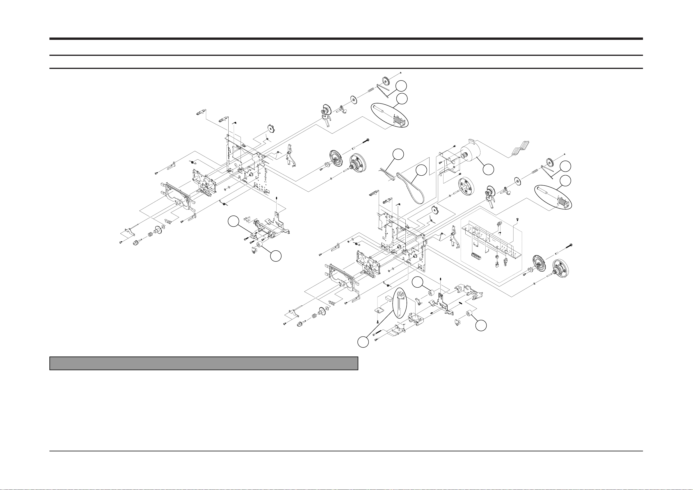
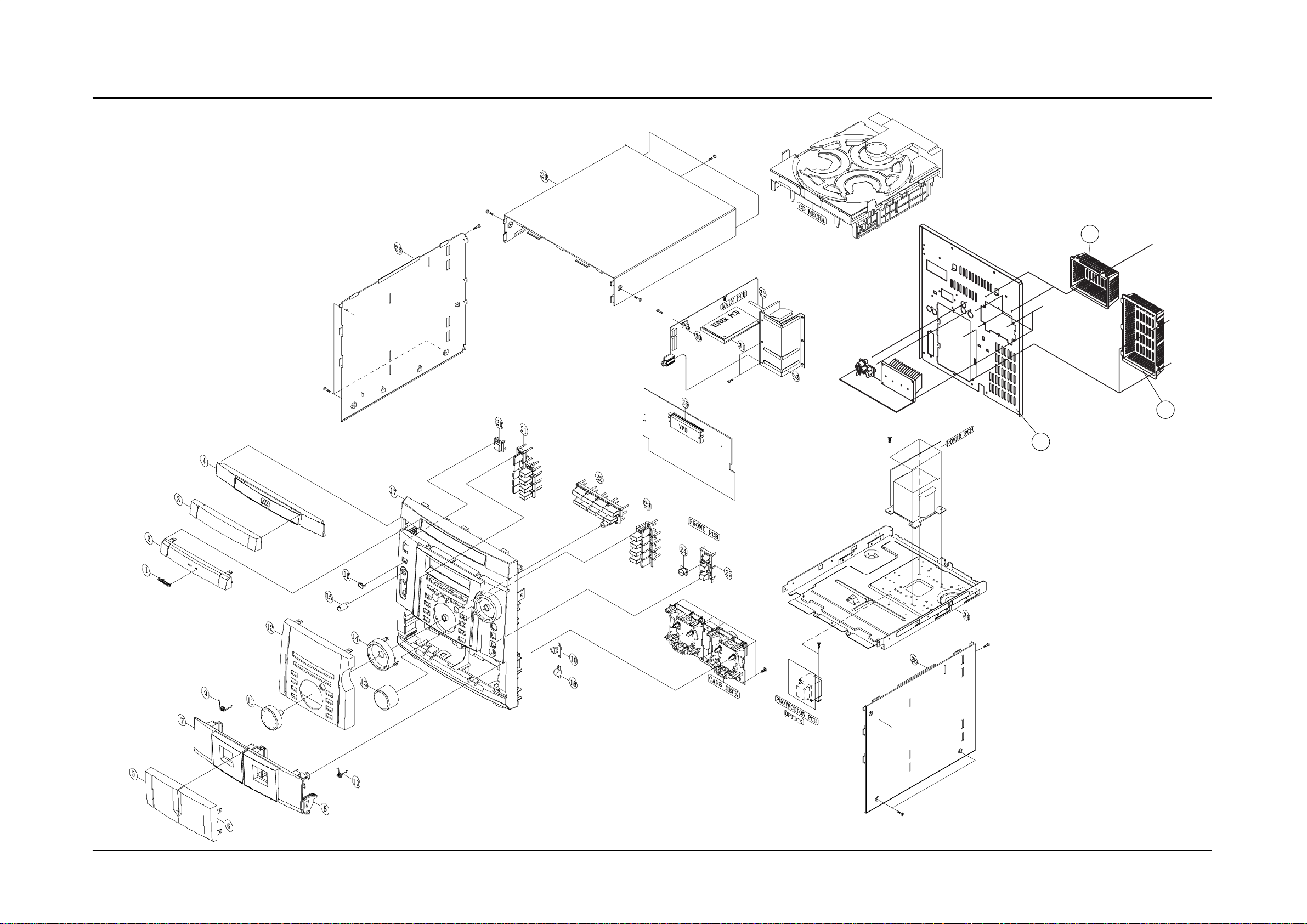
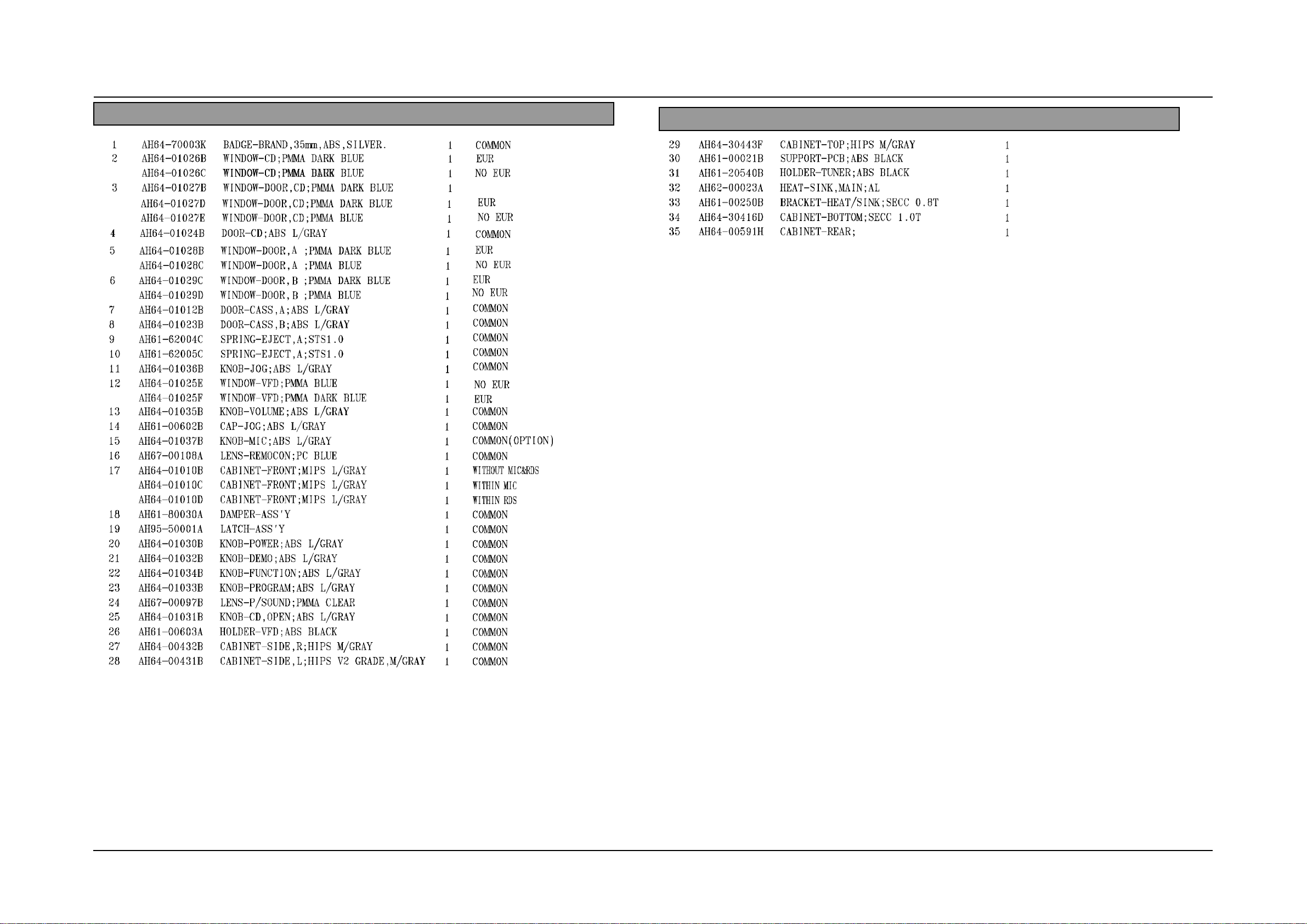
2-2 Total Exploded View and Parts List
35
36
37
Samsung Electronics 2-3
* Parts List of Total Exploded view
No. Code No. Description ; Specification Q’ty REMARK
No. Code No. Description ; Specification Q’ty REMARK
SECC T0.8
AH61-00604A
36
AH61-00278A
37
CAP-DVD;ABS
CAP-REAR;ABS
1
1
Samsung Electronics
2-4
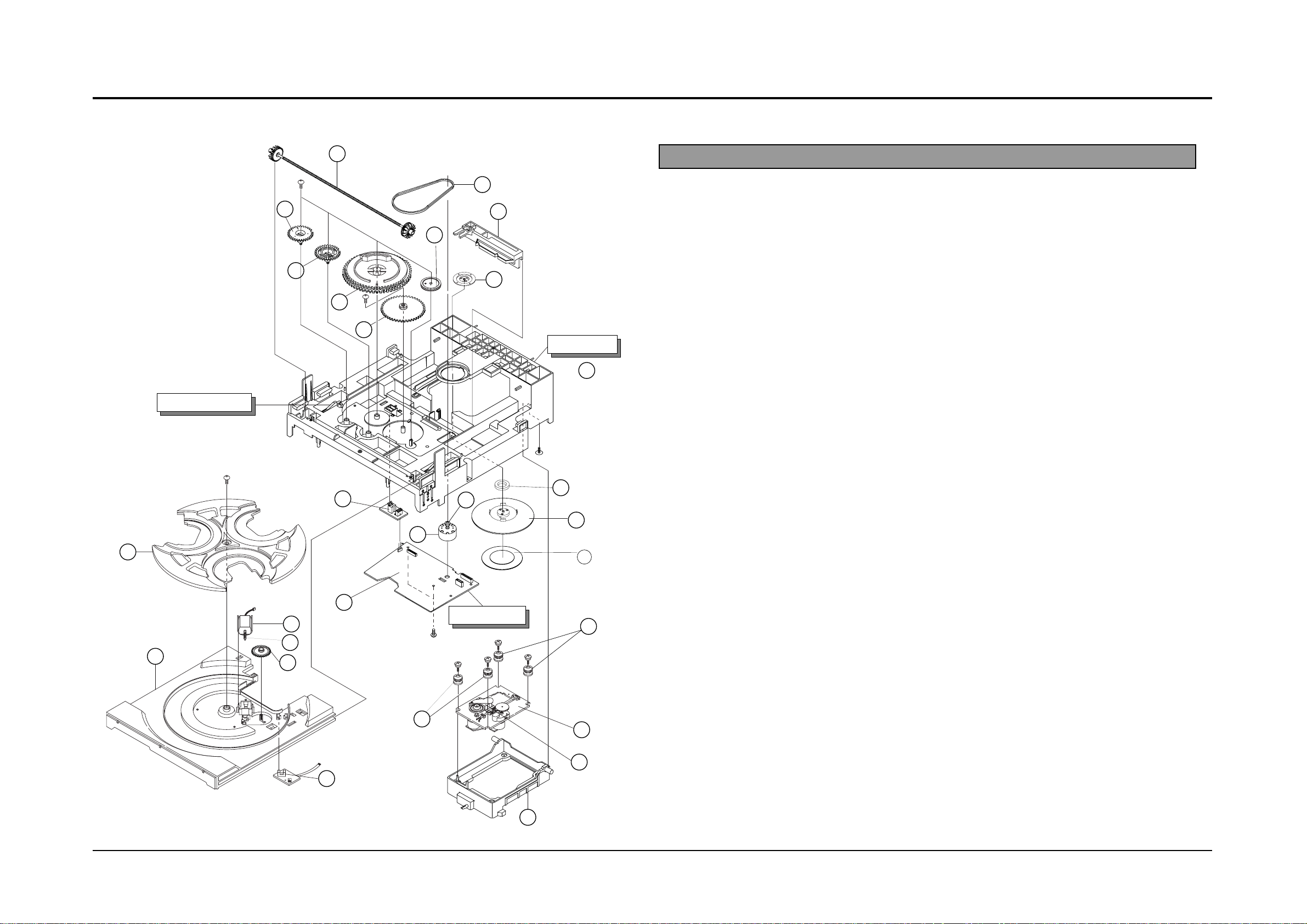
2-3 CD Deck Exploded View and Parts list
12
8
2
28
15
27
19
7
6
5
4
3
1
10
20
17
22
26
21
11
9
14
16
13
CD SUB PCB
TRAY STOPPER
24
23
25
BASE MAIN
18
No. Code No. Description Specification Remarks
AH97-00857A ASS’Y-DECK
G3HI-3CD/VCD
1 AH66-80022A SLIDER-CAM ABS HF-380 NTR
2 AH66-60034A BELT-LOAD CR
3 AH66-20186A GEAR-PULLEY POM (M90-44) WHT
4 AH66-20187A GEAR-LOAD POM (M90-44) BLK
5 AH66-20188B GEAR-CAM POM (M90-44) WHT
6 AH66-20189B GEAR-TRAY POM (M90-44) BLK
7 AH66-20190B GEAR-CONVERT POM (M90-44) WHT
8 AH66-20191A GEAR-SYNCRO ABS HF-380 NTR
9 AH66-20192A GEAR-WORM POM(M90-44),M0.5,PCD4.5
10 AH31-12001A MOTOR-LOADING FF-030PN-09120
11 AH66-20193A GEAR-ROULLETE POM(M90-44) BLK
12 AH63-00324A TRAY-ROULLETE ABS XR-401 BLK
13 AH63-00325A TRAY-DISC ABS BLK
14 AH32-10001F SENSOR KPI-L06
15 AH61-00837A BASE-MAIN ABS,NATURAL,CMS-300
16 3302-000159 MAGNET AC,3500-3800G,2.6-3.2MGOe,30
17 AH63-90053A TABLE-CHUCK ,ABS,+GF20%,BLK,
18 AH63-00068B SHEET-CHUCK SHEET,HYMERON,BLK,0.4T
19 3405-000101 SWITCH -MICRO MLS-24
20 AH31-10021A MOTOR-DC RF-500TB,9VDC/130MA
21 AH66-10008A PULLEY-MOTOR POM,BLK,CMS-CR3
22 AH73-10031A RUBBER-CD(R) SI,CMS-300,40,RED
23 AH91-60150C CDP DECK ASSY CMS-D73SG6U
24 AH66-30098A LEVER-LIFTER ABS BLK CMS-300
25 AH30-00007A PICK-UP SOH-AD3
26 AH73-10034A RUBBER-CD(G) SI,CMS-300,40,GREEN
27 AH92-00922A ASS’Y PCB CD MAIN
28 AH61-00225A BRKT-CHUCK SECL 0.8t
Samsung Electronics 2-5
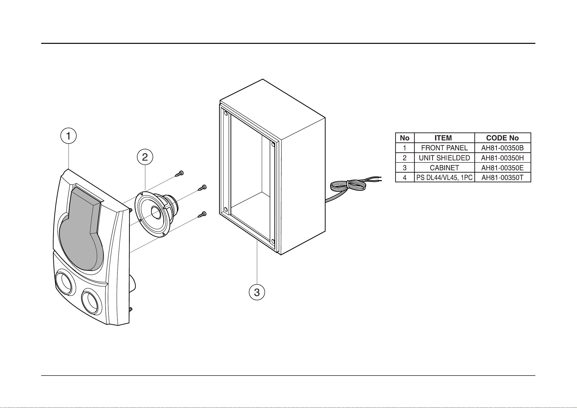
2-4 SPEAKER Exploded View and Parts list
*PS VL45E : AH81-00350P
* CAUSION : It is used the bonding, connet NET FRAME(or FRONT PANEL ASS’Y) to CABINET ASS’Y.
So when the disassembly, take extreme care not to demage the SPEAKER.
 Loading...