

SAMSUNG max920, max900 Alignment and Adjustments
OUTPUT
AM SSG
450KHZ
INPUT
AM ANT
IN
Speaker Terminal
60cm
TFT1
VTVM Oscilloscope
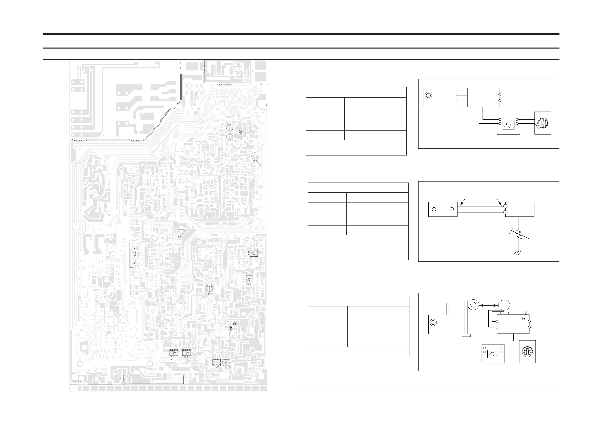
1. Alignment and Adjustments
1-1 Tuner
Samsung Electronics 1-1
FM THD Adjustment
Output
Output
1kHz 28dB
60 dB
Minumum Distortion (0.3% below)
(Figure 1-1)
SSG FREQ.
Adjustment
point
(TFT2)
98 MHz
FM DETECTOR COIL
AM(MW) I.F Adjustment
Maximum output (Figure 1-3)
SSG FREQ.
Frequency
Adjustment
point
(TFT1)
450 kHz
522 kHz
AM I.F COIL
FM Search Level Adjustment
Adjust IVR1 so that “TUNED” of FLT is
lighted (Figure 1-2)
4Gain : 20dB(CE standard)
Figure1-2 FM Auto Search Level Adjustment
Figure1-3 AM I.F Adjustment
Figure1-1 IF CENTER and THD Adjustment
SSG FREQ.
Adjustment
point
(TVR1)
98 MHz
BEACON
SENSITIVITY
SEMI-VR(20KΩ)
FM SSG
GND
28 dB
FM SSG
Output
GND
Speaker
Terminal
FM
Antenna
Terminal
Distortion Meter
Input
SET
Input
output
Oscilloscope
FM IN
FM Antenna
SET
TVR1
20KHz
SVR1
SVR2
* When adjusting T.H.D., readjust I/F coil on the Tuner Pack.
OUTPUT
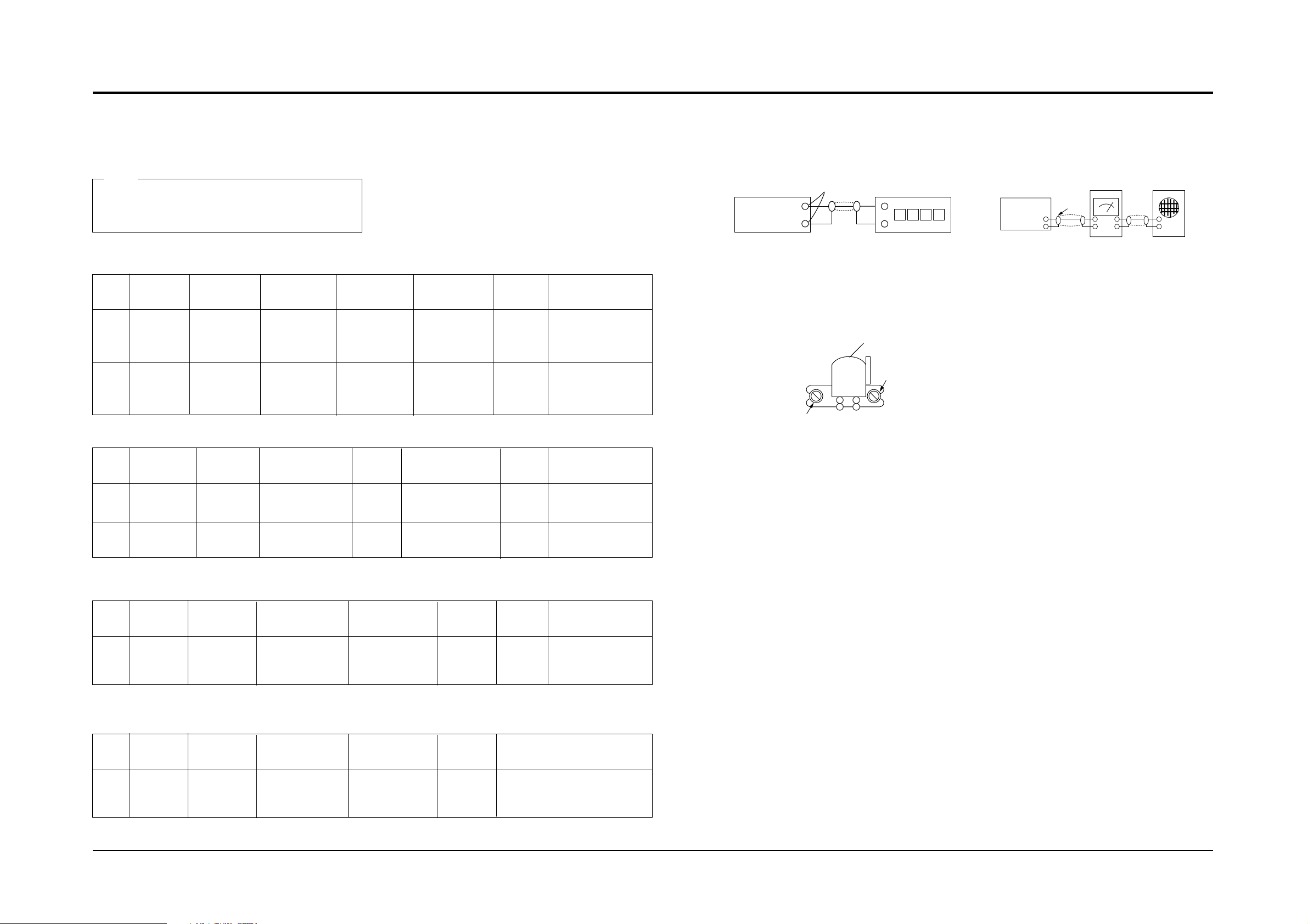
1-2-1 To Adjust Tape Speed
* Measuring tape: i) MTT-111 CN(or equivalent)
(Tapes recorded with 3kHz)
ii) MTT-5512 (or equivalent)
Notes
SPEED
Control
1
2
MTT-111N
(3KHZ)
MTT-111
(3KHZ)
3 kHZ ±1%
Fig. 1-4
Fig. 1-4
A&B Deck
deviation : 60Hz
-
5200~6600Hz
Check
Remark
Standard
Figure
Adjust
Point
Item
Step
Tape
SVR3
No
Adjustment
HI SPEED
Control
Azimuth
1
MTT-111CN
8KHZ
Fig.1-4
Fig. 1-6
Output:Maximum
Remark
Standard
Figure
Adjust
Point
Item
Step
Tape
Adjustment
screw of HEAD
L,R
Unbalance
1
2
MTT-112B
(1KHZ)
MTT-5512
±5dB
Fig. 1-5
Fig. 1-5
SPEAKER
VTVM (A-DECK)
60KHZ±1KHZ(MAX900)
85KHZ±1KHZ(MAX920)
SP2
Remark
Frequency
Range
Figure
Adjust
Point
Item
Step
Tape
SVR4
SFT1
Record
Frequency
Speaker
Terminal
output
Frequency Counter
Figure 1-4
Figure 1-6
Recording /Play head
AZIMUTH control
Figure 1-5
In Out
Cassette Deck
Oscilloscope
SET
(GND)
VTVM
V H
1-2 Cassette Deck
Alignment and Adjustments
2-2
Samsung Electronics
SP2
SPEAKER
PreSetup
Press play
button after
puting tape into
the Deck1
Press play
button after
puting tape into
the Deck1
PreSetup
Press Rec button after
connecting (Fig1-5)
Press Rec button after
connecting (Fig1-5)
PreSetup
Press Play button
after puting tape
into the Deck1
Rec Bias
Voltage
1
MTT-5512
(3KHZ)
7V±0.5V
Connete to MWF6 from
AC Meter.
Remark
Votage
Range
Adjust
Point
Item
Step
Tape
SVR1
SVR2
PreSetup
Press Rec button
after puting tape
into the Deck1
- Adjust SPEED Control
- Adjust Record Frequency
- Adjust Azimuth
- Adjust Rec Bias Voltage(Only MAX920 Model)
 Loading...