

Page 1
4. Alignment and Adjustments
4-1 Tuner
Samsung Electronics 4-1
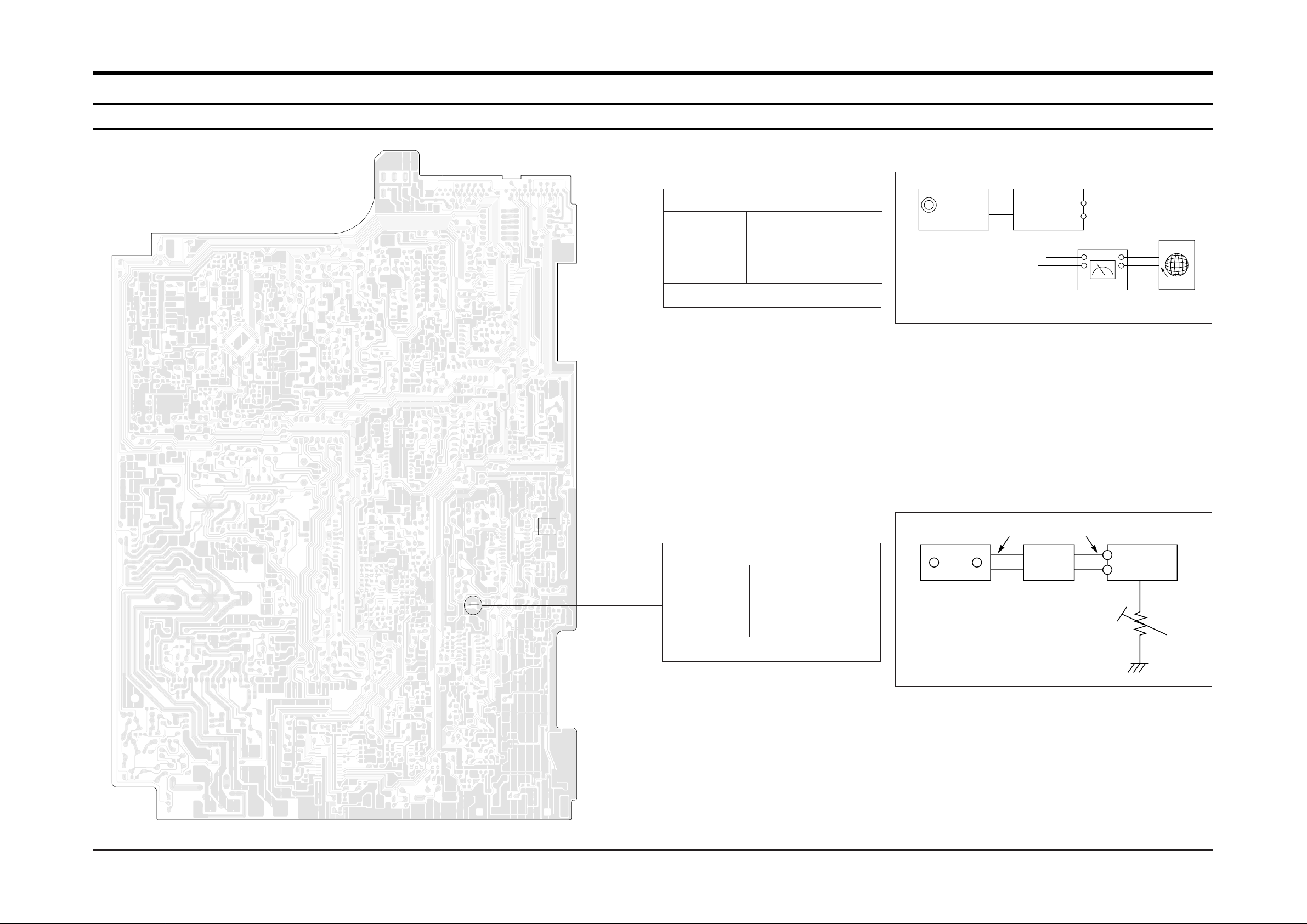
FM THD Adjustment
Minumum Distortion (Figure 4-1)
SSG FREQ.
Adjustment
point
(IFT6)
98 MHz
FM DETECTOR COIL
FM Search Level Adjustment
“TUNED” is shown on FLT (Figure 4-2)
Figure4-2 FM Auto Search Level Adjustment
Figure4-1 IF CENTER and THD Adjustment
SSG FREQ.
Adjustment
point
(MSR1)
98 MHz
SEMI-VR(5KB)
FM SSG
GND
30 dB
FM SSG
Output
GND
Speaker
Terminal
FM
Antenna
Terminal
Distortion Meter
Input
SET
Input
output
Oscilloscope
75Ω
Dummy
FM IN
FM Antenna
SET
5 kB
IFT6
FM T.H.D
MSR1
FM TUNED
Page 2
4-2 Samsung Electronics
Alignment and Adjustments
4-2 Cassette Deck
4-2-1 To Adjust Tape Speed
1) Measuring tape: i) MTT-111 (or equivalent)
(Tapes recorded with 3kHz)
ii) MTT-5512 (or equivalent)
2) Connect the cassette deck to the frequency counter
as in figure 4-3.
1) Before the actual adjustment, clean the replay/recording
head.
2) Measuring tape :
i) MTT-114NA(or equivalent 12.5kHz AZIMUTH control)
ii) MTT-150(or equivalent : Dolby level 200nwb/m)
3) Dolby NR SW OFF
4) The cassette deck is connections as shown in figure 4-5.
Notes
Notes
NOR
SPEED
Control
counter
1
2
OUT
(connected
to the frequency
counter)
Turn DSR5 to
left and right
3KHz ±1%
5700 ~ 6300KHZ
Fixed
Check
Remark
Standard
To Adjust
Pre-Setup
Item
Step
Pre-Setup
Condition
Same as above
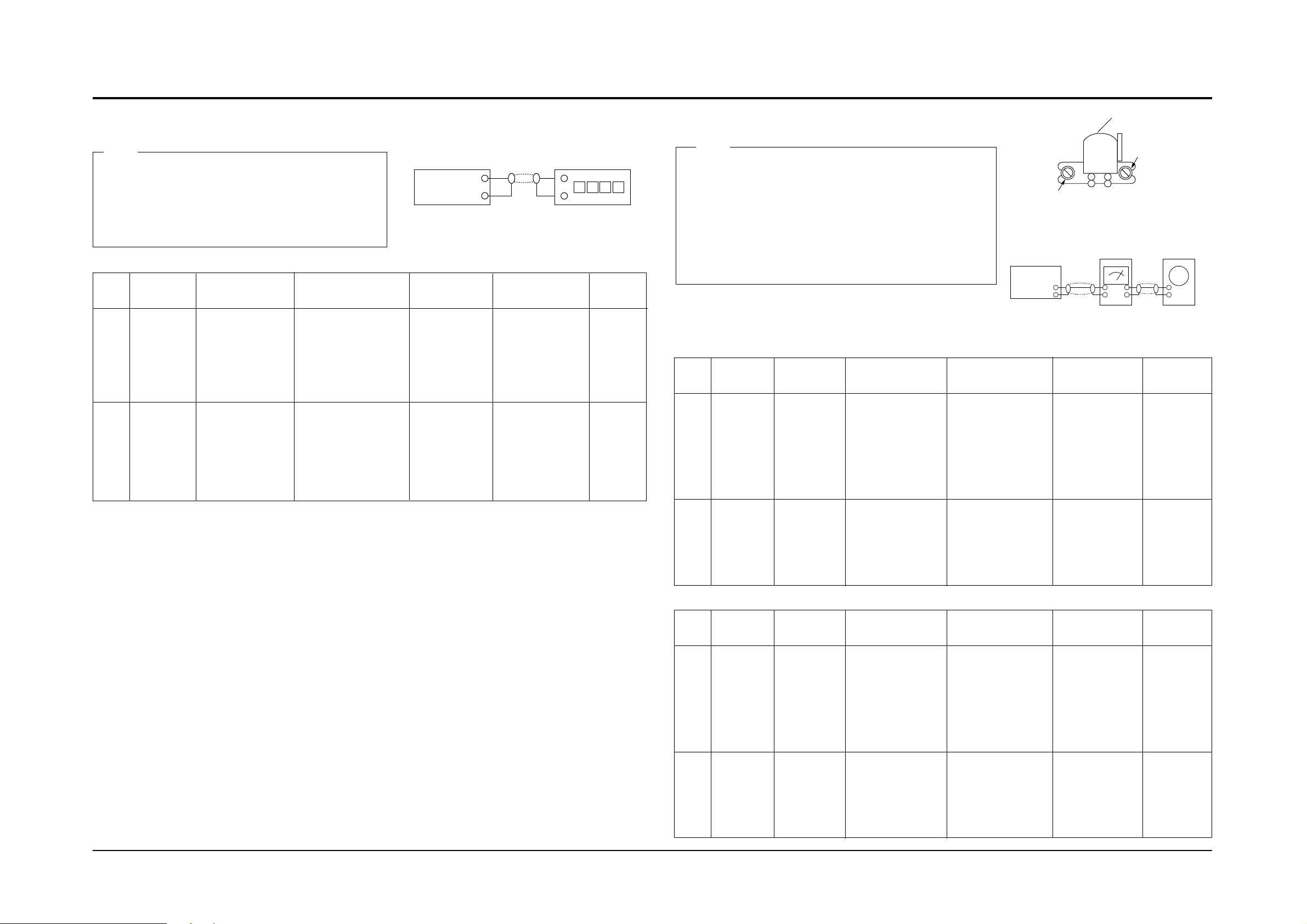
1) 1-Deck:MTT-111
2) Press PLAY
SW button
3) 2-Deck:Same
as below
1) 1-Deck:MTT-111
2) 2-Deck:MTT-5512
3) Press Hi Speed
dubbing SW button
HI SPEED
Control
AZIMUTH
1
2
TP3 OUT
(VTVM is
connected to
the scope)
1) T urn the control
knob to as shown
in Figure4-4.
2) Adjust the right
control screw to
playback REV . Mode
Max output
and same phase
(both channels)
After
adjustment
secure it with
REGION
LOCK.
100mV ±0.5dB
L-CH:T urn DSR3L
to the right and
left
R-CH:Fixed
See the
diagram for
adjustment
locations.
Remark
Standard
To Adjust
Pre-Setup
Item
Step
Pre-Setup
Condition
Same as
above
After putting MTT 114NA into Deck 1
1) Press FWD PLAY
button.
2) Press REV PLAY
button.
PLAY MTT-150
on Deck 1.
PlayBack
out Level
AZIMUTH
1
2
TP3 OUT
(VTVM is
connected to
the scope)
1) T urn the control
knob to as shown
in Figure4-4.
2)Adjust the right
control screw to
playback REV . Mode
Max output
and same phase
(both channels)
After
adjustment
secure it with
REGION
LOCK.
100mV ±0.5dB
L-CH:T urn DSR4L
to the right and
left
R-CH:Fixed
See the
diagram for
adjustment
locations.
Remark
Standard
To Adjust
Pre-Setup
Item
Step
Pre-Setup
Condition
Same as
above
After putting MTT 114NA into Deck 2
1)Press FWD PLAY
button.
2)Press REV PLAY
button.
PLAY MTT-150
on Deck 2.
PlayBack
out Level
4-2-2 To Adjust Replay Head
@ Adjust 2-Deck Replay Level
! Adjust 1-Deck Replay Level
TP3
Cassette Deck
output
LINE OUT
Frequency Counter
Figure 4-3
Figure 4-4
Recording /Play head
REVERSE PLAY
AZIMUTH control knob
Figure 4-5
In Out
Cassette Deck
Oscilloscope
LINE OUT
TP3
(GND)
VTVM
V H
Page 3

1) Connect the measuring instruments as shown in Figure 4-6.
2) Set the DOLBY NR Switch off.
3) Measuring tape:
MTT-5512 (or equivalent: normal recording)
4) The input signals supply 400Hz 400mV into AUX IN of AMP (AUDIO OSC.)
Samsung Electronics 4-3
4-2-3 To Adjust PlayBack
Alignment and Adjustments
Normal
electric
current
for
recording
1
2
3
Connect to TP2
as in Figure4-6
and read VTVM
L-CH : DSR2L
to the right and
left.
R-CH : Fixed
VTVM
400mV ±5%
105KHz ±5%
VTVM
(7V ±5%)
Turn BIAS oscillator frequency
coil (LL3) to the
right and left.
L-CH: DSR1L and
R-CH: DSR1R to
the right and left
See diagram
for
adjustment
locations
See diagram
for
adjustment
locations
See diagram
for
adjustment
locations
Remark
Standard
To Adjust
Pre-Setup
Item
Step
Pre-Setup
Condition
Connect the
frequency
counter to TP
Connect to
TP1 as in Figure
4-6 and read the
VTVM
Insert MTT-5512
into Deck2, then
press REC button.
Insert MTT-5512 into
Deck2, then press
REC button.
Insert MTT-5512 into
Deck2, then press
REC button.
BIAS OSC.
Frequency
BIAS
Electric
current
Figure 4-6
Audio OSC.
Cassette Deck
Oscilloscope
AUX IN
LINE OUT
VTVM
IN
TP
IN OUT
NOTES
Page 4

4-3 CD
Alignment and Adjustments
4-4 Samsung Electronics
4-3-1 To Adjust FOCUS BIAS (STOP mode)
1. Set Volt/Div of the oscilloscope to DC 100mV.
2. Ground the scope input and set the waveform to 0v, DC range.
3. Connect the GND terminal of the oscilloscope to Vref,
and (+) terminal to center of AP1.
4. Set NVR1704 to 0mV.
4-3-2 To Adjust Tracking Gain (PLAY mode)
1. Connect the ground terminal of the oscilloscope to Vref and (+) terminal to TP2.
2. Load and play the disc.
3. While the disc is running adjust the gain with NVR1701 as shown below.
4-3-3 To Adjust Focus Gain (PLAY mode)
1. Connect the ground terminal of the oscilloscope to Vref and (+) terminal to TP1.
2. Load and play the disc.
3. While the disc is running adjust the gain with NVR1702 as shown in the following figure.
4-3-4 To Adjust E/F Balance (PLAY mode)
1. Set Time/Div of the oscilloscope to 2mS.
2. Set Volt/Div of the oscilloscope to 0.5V.
3. Ground the scope input and set to DC, and then
set the DC range.
4. Connect the ground terminal of the oscilloscope to Vref
and (+)terminal to TP2.
5. Load and play the disc.
6. Turn NVR1701 counterclockwise to the minimum value.
7. Raise NVR1703 and adjust the waveform so that its middle
comes to ground of the oscilloscope. (Or, until the upper half
of waveform becomes symmetrical to the bottom half,A=B)
8. Adjust NVR1701 (arrow) for normal sound.
TP2
TP1
VR
NVR1704
NVR1703 NVR1702
NVR1701
TE CENTER
FE CENTER
E.F BAL
F.BIAS
0V
Normal Frequency
VOLT/DIV : 0.2V
TIME/DIV : 2mS
VOLT/DIV : 0.2V
TIME/DIV : 2mS
VOLT/DIV : 0.2V
TIME/DIV : 2mS
Low Frequency
High Frequency
A=B
0V
0V
0V
Normal Frequency
VOLT/DIV : 0.1V
TIME/DIV : 2mS
VOLT/DIV : 0.1V
TIME/DIV : 2mS
VOLT/DIV : 0.1V
TIME/DIV : 2mS
Low Frequency
High Frequency
0V
100mV
0V
250mV
0V
100mV
 Loading...