

Page 1
Disassembly and Assembly Instructions
7.
Disassembly
7-1.
1 2
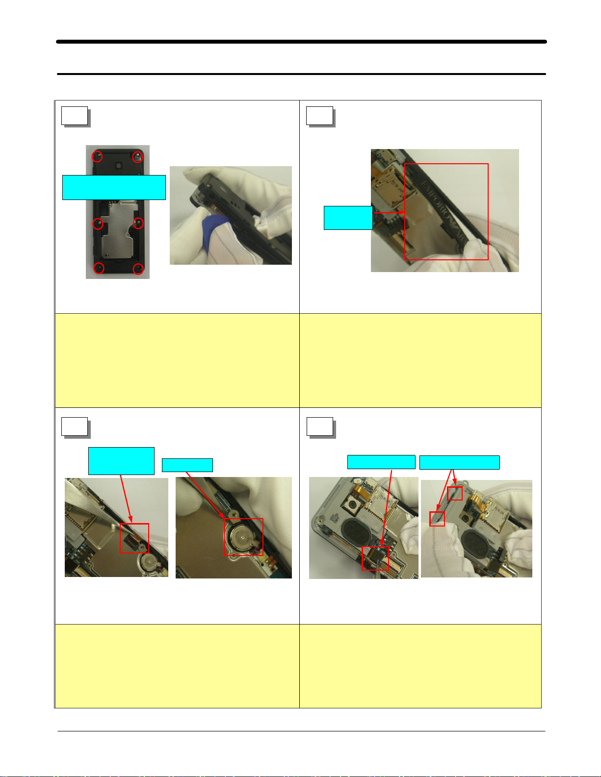
Screw(M1.4,L3.5)
1.2 ~ 1.3
Torque
Figure
<
Unscrew the REAR at the six points.
1)
Disassemble the REAR using the
2)
disassembeling knife.[Figure
Caution!
*
Be careful not to make scratch and molding
1)
Kgf.cm
1>
<
2]
Figure
2>
[Figure 1]
Disassemble the TEXT LOGO
1)
damage!
TEXT
LOGO
<
Figure
1>
[Figure 1]
3 4
TEXT LOGO
FPCB
Figure
<
Disassemble the TEXT LOGO from the
1)
1>
connector using the tweezers.
Insert the tweezers into disassembly hole and
2)
disassemble the MOTOR.
Caution!
*
Be careful not to damage FPCB!
1)
Be careful not to damage WIRE!
1)
MOTOR
[Figure 2]
Figure
<
[Figure 1]
2>
SSL Connector
Figure
<
Remove the SSL connector using the
1)
tweezers.[Figure
Check up the upper side of SSL.
2)
Caution!
*
Be careful not to damage FPCB!
1)
1>
1]
HOOK 2 POINT
7-1
SAMSUNG Proprietary-Contents may change without notice
This Document can not be used without Samsung's authorization
Page 2
Exploded View and Parts List
5 6
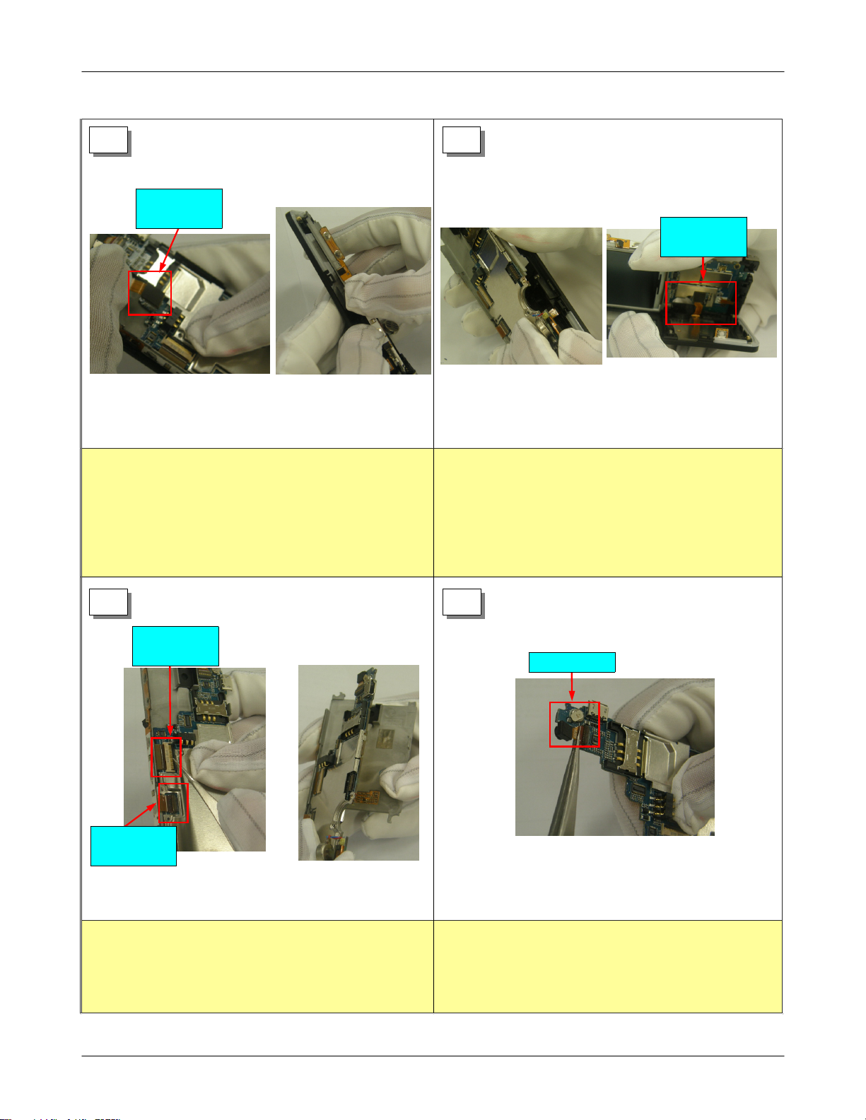
CAMERA
3M
CONNECTOR
Figure
Figure
<
Remove the3Mega Camera
1)
Separate the right side of FRONT and remove
2)
the PBA.
Caution!
*
Be careful not to damage FPCB!
1)
Be careful not to make scratch and molding
1)
damage LED FRONT
1>
[Figure 2]
!
<
[Figure 1]
2>
KRY PBA
CONNECTOR
Figure
<
PushtheleftsideofFRONTandremove
1)
PBA.[Figure
1>
1]
<
Figure
2) Separate the KEY PBA CONNECTOR[Figure 2]
Caution!
*
When PBA is separated,
1)
Be careful not to damage KEY PBA FPCB
2>
솓
!
7 8
LCD
CONNECTOR
SIDE KEY
CONNECTOR
Figure
Figure
<
Separate the LCD and SIDE KEY connector
1)
1>
using the tweezers.[Figure
Remove the BRACKET from PBA.[Figure
2)
Caution!
*
Be careful not to damage FPCB!
1)
<
1]
2>
2]
CIF CAMERA
Figure
<
Separate the CIF CAMERA using the
1)
tweezers.[Figure
Caution!
*
Be careful not to damage FPCB!
1)
1]
1>
7-2
SAMSUNG Proprietary-Contents may change without notice
This Document can not be used without Samsung's authorization
Page 3

Exploded View and Parts List
Assembly
7-2.
1 2
CIF CAMERA
Figure
<
Insert the CIF CAMERA using the tweezers.
1)
Figure
[
Insert the LCD FPCB by the guide line
2)
Caution!
*
Be careful not to damage FPCB!
1)
Check up the guide line when connector is
2)
1]
1>
<
Figure
LCD
CONNECTOR
2>
.[Figure 2]
inserted.
3 4
SIDEKEY
FPCB
CONNECTOR
Figure
<
Insert the side FPCB
1)
2) Adjust
theguideandassembletheSIDEKEY
FPCB.
Caution!
*
Check up the guide line when connector is
1)
1>
.[Figure1]
[Figure 2]
Guide
<
Figure
inserted.
Check up the basis guide when FPCB is
2)
assembled.
2>
KEY PBA
CONNECTOR
Figure
<
Check the position of the KEY PBA
1)
CONNECTOR.
1>
[Figure 1]
KEY PBA
CONNECTOR
Figure
<
2>
2) Assembel the KEY PBA CONNECTOR into PBA.
[Figure 2]
Caution!
*
Be sure to
1)
connect the connectors!
<
LED
Figure
1>
<
HOOK
Figure
1) Assemble the PBA on the FRONT from right side.
[Figure 1]
Pull the HOOK of Front and assemble the PBA.
2)
[Figure 2]
Caution!
*
Be careful not to damage LED When the PBA
1)
is assembled.
Check up the assembling condition of shield
2)
SHIELD CAN HOOK.
7-3
2>
SAMSUNG Proprietary-Contents may change without notice
This Document can not be used without Samsung's authorization
Page 4

5 6
<
MOTOR
Figure
2><
CIF CAMERA
Figure
1>
Insert the CIF CAMERA into the FRONT using
1)
the tweezers.[Figure
Twist the motor one andahalf and assemble
2)
the motor.[Figure
Caution!
*
Be careful when motor is assembled. WIRE!
1)
1]
2]
Exploded View and Parts List
CAMERA
3M
CONNECTOR
Figure
<
Assemble the3M Camera connector and
1)
1>
SD Card FPCB
Module connector
Figure
<
assemble the camera into the camera guide.
Insert the SD Card FPCB Module connector.
2)
Figure
[
Caution!
*
Be sure to connect the CAMERA connector
1)
Be sure to connect the SD Card connector
2)
2]
2>
s!
s!
7 8
SSL
CONNECTOR
Figure
<
Assemble the SSL into PBA and insert the
1)
connector.[Figure
Push and Assemble the upper side Hook of the
2)
SSL[Figure
Caution!
*
Be sure to connect the connector
1)
Check the condition of hook connection.
2)
1>
1]
2]
<
Hook
Figure
2>
s!
TEXT LOGO
FPCB
Figure
<
Assemble the TEXT LOGO FPCB into
1)
FRONT.[Figure
Insert the TEXT LOGO FPCB into connector.
2)
Figure
[
Caution!
*
Be careful not to damage FPCB!
1)
Check the silk line after FPCB is inserted.
2)
2]
1>
1]
TEXT LOGO
FPCB Connector
Figure
<
2>
7-4
SAMSUNG Proprietary-Contents may change without notice
This Document can not be used without Samsung's authorization
Page 5

Exploded View and Parts List
9 10
MUSIC KEY
TEXT LOGO
Figure
<
Assemble the TEXT LOGO into the FRONT.
1)
Figure
[
Assemble the MUSIC KEY into the FRONT
2)
Figure
[
Caution!
*
Be careful the reverse insertion when MUSIC
1)
1]
2]
1>
<
Figure
2>
.
KEY is assembled.
Figure
<
CovertheREARandpushtheleftandright
1)
Figure
[
1]
1>
.
11
Screw(M1.4,L3.5)
1.2 ~ 1.3
Torque
Figure
<
crew the REAR at the six points.[Figure
1) S
Check the look of Set.[Figure
2)
Caution!
*
Toque kgf.cm
1)
Kgf.cm
1> <
2]
Figure
1>
1]
7-5
SAMSUNG Proprietary-Contents may change without notice
This Document can not be used without Samsung's authorization
 Loading...