

Page 1

4 Alignments and Adjustments
LTP1745/LTP1745U/LTP2045 4-1
4 Alignments and Adjustments
4-1 General Alignment Instuction
1. Usually, a color TV-VCR needs only slight touch-up adjustment upon installation.
Check the basic characteristics such as height, horizontal and vertical sync.
2. Use the specified test equipment or its equivalent.
3. Correct impedance matching is essential.
4. Avoid overload. Excessive signal from a sweep generator might overload the front-end of the TV.
When inserting signal markers, do not allow the marker generator to distort test result.
5. Connect the TV only to an DC power source with voltage and frequency as specified on
the backcover nameplate.
6. Do not attempt to connect or disconnect any wire while the TV is turned on.
Make sure that the power cord is disconnected before replacing any parts.
7. To protect aganist shock hazard, use an isolation transform.
Page 2
4 Alignments and Adjustments
4-2 LTP1745/LTP1745U/LTP2045
4-2 Factory Mode Adjustments
4-2-1 Entering Factory Mode
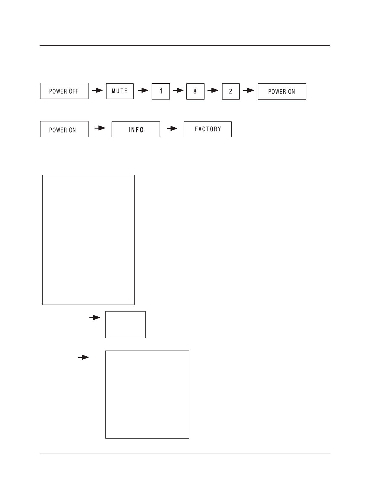
1. To enter “Service Mode” Press the remote -control keys in this sequence :
- If you do not have Factory remote - control
- If you have Factory remote - control
4-2-2 Factory Mode Tree (U.S. Only)
1. Calibration
1. Calibration VCTi
Component
PC
2. Option 1. Video Mute O
2. Auto Power On
3. Panel XGA
4. Inch 15
5. Antenna Osd off
6. High Deviation off
7. V-Chip USA
8. Acc/ACM O
9. Gamma LUT O
10. ESM On
2. Option
3. W/B
4. ADC
5. VCTi 127
6. ACC/ACM
7. Test Pattern 0
8. Bus Stop off
9. Check Sum 0
10. Reset
T- VNCNUS - 0016 2004/01/31
Page 3

4 Alignments and Adjustments
LTP1745/LTP1745U/LTP2045 4-3
3. W/B(1)
3. W/B(2)
R level 128
G level 128
B level 128
R gain 127
G gain 127
B gain 127
g Sub Color 0
g Sub Tint 50
Recall
RF RF
[Initial Data] [AdjustData]
RemarkAdjustment item
Item
Cannot be adjustment
Adjustment
External input
External input
External input
External input
Cannot be adjustment
Cannot be adjustment
Cannot be adjustment
Cannot be adjustment
Cannot be adjustment
Red level ADJ[0~255] 128 128
Blue le
vel
128 FIXGreen level ADJ[0~255] 128 128
Blue level FIX[0~ 255] 128 128
Red Gain FIX[0~ 255] 128 135
Red Gain 135 FIX
`
Green Gain ADJ[0~255] 128 135
Blue Gain ADJ[0~255] 128 135
gSUB Color FIX[0~ 255] 0 0
gSUB Tint FIX[0~ 255] 50 50
Factory Recall
*A/S : Micom Initial Data Wr ite
Dynamic RemarkCool 1
MODE RF[A DJ] COMPONENT 480i COMPONENT 480P PC
* W/B connot be
adjusted in
COMPONENT &PC
* Only x,y axes can
be adusted in
High & Low Light
Signal S ource
ABL Patter
Process
n
[MSPG925LTH]
ABL Pattern
[MSPG925LTH]
ABL Pattern
[MSPG925LTH]
ABL Pattern
[MSPG925LTH]
W/B
SPEC
High
x=270 2, y=270 2
Low
x=270 2, y=270 2
W/B
SPEC
High
x=270 10,y =270 10 , Y=22. 0 [FL] x=270 20,y=270 20 x=270 20, y=275 20 x=250 30, y=260 30
Low
x=270 10,y =270 10 , Y=0. 3 0. 1 [ FL] x=260 20,y=260 20 x=280 20, y=290 20 x=250 30, y=255 30
+_
+_
+_
+_
+_
+_
+_+_
+_
+_
+_+_
+_
+_
+_+_
+_+_
+_
+_
Page 4

4 Alignments and Adjustments
4-4 LTP1745/LTP1745U/LTP2045
4. ADC
R offset
VCTi
53
G offset
43
B offset
47
R gain 0
125
R gain 1
1
G gain 0
122
G gain 1
1
B gain 0
134
B gain 1
1
R offset
Compenent
113
G offset
85
B offset
83
R gain 0
207
R gain 1
1
G gain 0
31
G gain 1
1
B gain 0
205
B gain 1
1
R offset
PC
66
G offset
63
B offset
51
R gain 0
54
R gain 1
1
G gain 0
62
G gain 1
1
B gain 0
66
B gain 1
1
5. VCT
R Drive
255
G Drive
255
B Drive
255
Sub Contrast
44
Sub Bright
0
Sub Sharp
15
Sub Color
7
Sub Tint
50
Sub Coring
5
RF AGC
0
Vpeaking
6
CTI Gain
3
CTI Coring
5
LMIXOFS
6
PKCF
3
AGCADJ1
32
LTI Gain
15
6. ACC/ ACM
Y Max D
7
Y Scl Thr
64
Y Scl A
5
Y Scl B
0
A Ctrl
0
A Snslp
8
T Dixel
12
Lower End
80
Mid Start
30
Mid End
100
Up Start
40
Low Sn Thr
60
Up Sn Thr
0
Y Min
10
Y Max
255
Ym Div Slp
128
Fr Age
1
Fr App
0
Esm Ctrl
127
Page 5

4 Alignments and Adjustments
LTP1745/LTP1745U/LTP2045 4-5
7. Test Pattern ( Test Pattern of VCTi)
1) VCTi
2) Toshiba
3) Gray Bar
4) Gray
5) Green
6) Color Bar
7) Cross
8. Bus Stop
- Bus stop is used data communication.
9. Chcek Sum
- Display the current check sum size of the MICOM.
10. Reset
- Initializes the data in the MICOM.
11. T-VNCNUS-0016 2004/01/31
- Display the MICOM program version.
4-2-3 White Balance
High Low
270, 270 270, 270
x, y x, y
Page 6

4 Alignments and Adjustments
4-6 LTP1745/LTP1745U/LTP2045
4-2-4 Calibration
(1) RF,VIDEO, S-VI DEO :
Factory M ode Calibration VCTi Ente
r
(2)Compoent:adjust in 16 Gray Pattern of 480p.
Based on Master device (VIDEO SIGNAL GENERATOR MSPG-925F)
after adjusting to 16 Gray Pattern (Model : 212, Pattern : 17)
F
ac
tory M od
e
Calibration Component Enter
(3)PC:adjust in VGA MODE.
Based on Master device
execute Auto Adjustment in Cross Hatch (also called Combination) (Model : 10, Pattern : 25)
(VIDEO SIGNAL GENERATORMSPG-925F)
After adjusting 16 Gray Pattern (Model : 10, Pattern : 17)
Fac
t
ory M ode Calibration PC Ente
r
(4) check 4.ADC of Factory Mode. Adjustment can be done as below.
Value variation can be 10~20.
VCTi Compone
nt
PC
Roff
set
set
set
set
set
set
set
set
set
FIX[ 0~127] 46 Roff FIX[0~127] 64 Roff FI X[0~127] 50
Goff FIX[0~127] 66 Goff FIX[0~127] 86 Goff FIX[ 0~127] 54
Boff FIX[0~127] 68 Boff FIX[0~127] 64 Boff FIX[0~127] 44
Rg
ain0
FI X[ 0~255]
251 Rg
ain0
FI X[ 0~255]
215 Rg
ain0
FI X[ 0~255]
115
Rg
ain1
FI X[ 0 ~ 1]
0 Rg
ain1
FI X[ 0 ~ 1]
1 Rg
ain1
FI X[ 0 ~ 1]
1
Gg
ain0
FI X[ 0~255]
255 Gg
ain0
FI X[ 0~255]
247 Gg
ain0
FI X[ 0~255]
120
Gg
ain1
FI X[ 0 ~ 1]
0 Gg
ain1
FI X[ 0 ~ 1]
0 Gg
ain1
FI X[ 0 ~ 1]
1
Bg
ain0
FI X[ 0~255]
253 Bg
ain0
FI X[ 0~255]
215 Bg
ain0
FI X[ 0~255]
114
Bg
ain1
FI X[ 0 ~ 1]
0 Bg
ain1
FI X[ 0 ~ 1]
1 Bg
ain1
FI X[ 0 ~ 1]
1
+
_
 Loading...