

Samsung LTM1775W, LTM1575W Owner’s Manual
PI D ir 7_[e_] e[e]tauuun _v_ [o]_
..............-Owner's
Instructions
l Warninq ! Important
Safety Instructions
CAUTION
CAUTION: TO REDUCE THE RISK OF ELECTRIC SHOCK, DO NOT
REMOVE COVER (OR BACK). NO USER SERVICEABLE PARTS INSIDE.
REFER SERVICING TO QUALIFIED SERVICE PERSONNEL.
dangerous to make any kind of contact with any inside part of
This symbol indicates high voltage is present inside, It is
this product.
This symbol alerts you that important literature concerning
operation and maintenance has been included with this producL
Note to CATV system installer: This reminder is provided to call CATV system
installer's attention to Article 820 40 of the National Electrical Code (Section 54 of
Canadian Electrical Code, Part I), that provides guidelines for proper grounding
and, in particular, specifies that the cable ground shall be connected to the
grounding system of the building as close to the point of cable entry as practical.
Caution: FCC/CSA regulations state that any unauthorized ehanges or modillca
tlons to this equipment may void the user's authority to operate it.
Caution: To prevent etectric shoek, match the wide Made of plug to the wide slot,
and fully insert the plug.
Attention: pour eviter les chocs electriques, introduire la lame le ptus large de la
fiche dans la borne correspondante de la prise et pousserjusqu'au fond.
Important: One Federal Court has held that unauthorized recording of
copyrighted TV programs is an infringement of U.S. copyright laws.
Certain Canadian programs may also be copyrighted and any unauthorized
recording in whole or in part may be in violation of these rights.
To prevent damage which may result in fire or electric shock
hazard, do not expose this appliance to rain or moisture.
Thank You for Choosing Samsung
Thank you for choosing Samsung! Your new Samsung TV represents the latest in television
technology, We designed it with easy to use on screen menus and closed captioning capabili
ties, makhlg it one of the best products in its class. We are proud to offbr you a product that
will provide convenient, dependable service and enjoyment fur years to come.
Important Safety Information
Always be careful when using your TV receiver. '1"oreduce the risk of fire, electrical shock,
and other injuries, keep these safety precautions in mind when installing, using, and
maintaining your machine.
• Read all safety and operating instructions before operating your T_
• Keep the safety and operating instructions for future ieference.
• Heed all warnings on the TV i-eceiver and in the operating instructions.
• Follow all operating and use instructions.
• Unplug the TV receiver from the wall outlet befure cleaning. Use a damp cloth; do not use
liquid or aerosol cleaners.
• Never add any attachments and/or equipment without approval of the manufacturer. Such
additions can inci-ease the risk of fire, electric shock, or other personal injury,
• Do not use the TV receiver where contact with or immersion in water is a possibility, such as
near bath tubs, sinks, washing machines, swimming pools, etc.
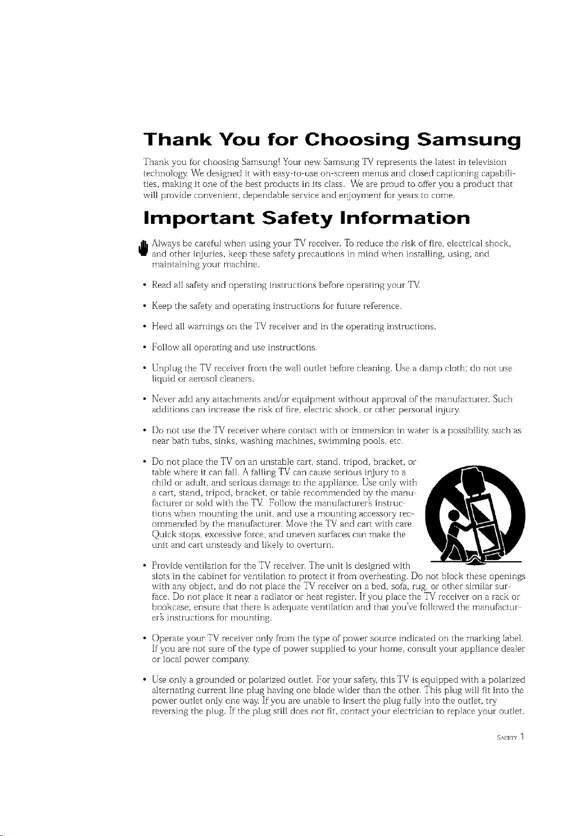
• Do not place the TV on an unstable cart, stand, tripod, bracket, or
table where it can fail. A falling TV can cause serious injury to a
child or adult, and serious damage to the appliance. Use only with
a cart, stand, tripod, bracket, or table recommended by the manu
facturer or sold with the TV_ Follow the manufacturer[ instruc
tions when mounting the unit, and use a mounting accessory rec
ommended by the manufacturer. Move the TV and cart with care.
Quick stops, excessive force, and uneven surfaces can make the
unit and cart unsteady and likely to overturn.
• Provide ventilation fur the TV receiver. The unitis designed with
slots in the cabinet for ventilation to pi-otect it from overheating. Do not block these openings
with any object, and do not place the TV receiver on a bed, sofa, rug, or other similar sur
face. Do not place it near a radiator or beat i-egister. If you place the TV receiver on a rack or
bookcase, ensure that there is adequate ventilation and that you've followed the manufactur
er_ instructions fur mounting.
• Operate your TV receiver only from the type of power source indicated on the marking label.
If you are not sure of the type of power supplied to your home, consult your appliance dealer
orlocal power company
• Use only a grounded or polarized outlet. For your safety, this TV is equipped with a polarized
alternating current line plug having one blade wider than the other. This plug will fit into the
power outlet only one way If you are unable to insert the plug fully into the outlet, try
reversing the plug. If the plug still does not fit, contact your electrician to replace your outlet.
SAFFIY 1
• Protect the power cord. Power supply cords should be routed so that they won't be walked
on or pinched by objects placed on or against them. Pay particular attention to cords at
plugs, convenience receptacles, and the point where they exit from the unit.
• Unplug the TV from the wall outlet and disconnect the antenna or cable system during a
lightning storm or when left unattended and unused fur long periods of thne. This will pre
vent damage to the unit due to lightning and power line surges.
Avoid overhead power lines. An outside antenna system should not be placed in the vicinity
of overhead power lines or other electric light or power circuits or where it can fail into such
power lines or circuits. When installing an outside antenna system, be extremely careflnl to
keep from touching the power lines or circuits. Contact with such lines can be fatal.
• Do not overload the wall outlet or extension cords. Overloading can result in fire or electric
shock.
• Do not insert anything through the openings in the unit, where they can touch dangerous
voltage points or damage parts. Never spill liquid of any kind on the TV[
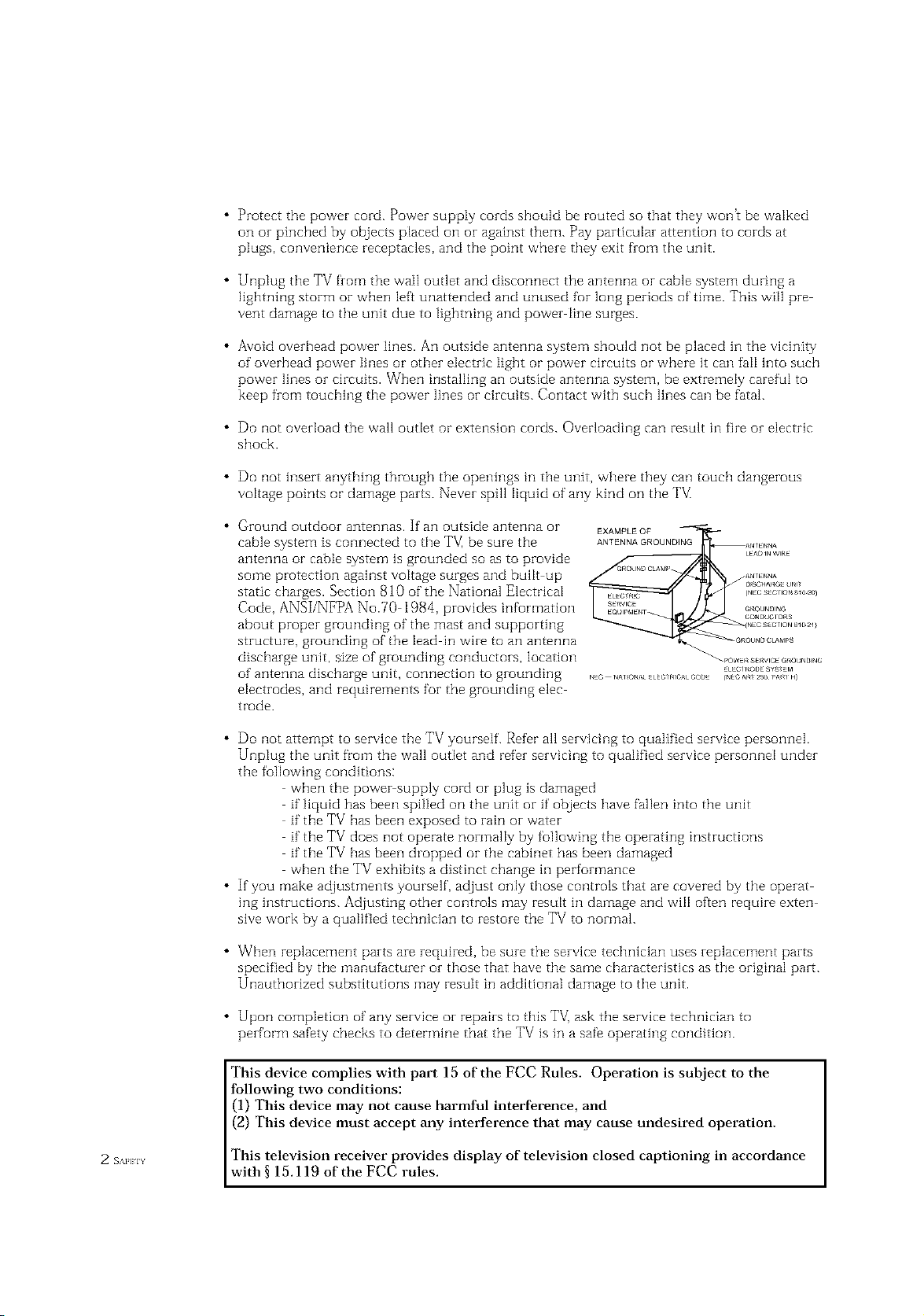
Ground outdoor antennas. If an outside antenna or
cable system is connected to the TV, be sure the
antenna or cable system is grounded so as to provide
some protection against voltage surges and built up
static charges. Section 810 of the National Electrical
EXAMPLEOF
ANTENNA GROUNDING
Code, ANSI/NFPA No.70 1984, provides information
about proper grounding of the mast and supporting
structure, grounding of the lead in wire to an antenna
discharge unit, size of grounding conductors, location
of antenna discharge unit, connection to grounding
electrodes, and requirements for the grounding elec
trode.
• Do not attempt to service the TV yourself. Refer all servicing to qualified service personnel.
Unplug the unit from the wall outlet and refer servicing to qualified service personnel under
the following conditions:
when the power supply cord or plug is damaged
if"liquid has been spilled on the unit or if' objects have fallen into the unit
if"the TV has been exposed to rain or water
if the TV does not operate normally by following the operating instructions
if the TV has been dropped or the cabinet has been damaged
when the TV exhibits a distinct change in performance
• If you make adjustments yourself, adjust only those controls that are covered by the operat
ing hlstructions. Adjusting other controls may result in damage and wfl[ often require exten
sive work by a qualified technician to restore the TV to normal.
• When replacement parts are required, be sure the service technician uses replacement parts
specified by the manufacturer or those that have the same characteristics as the original part.
Unauthorized substitutions may result in additional damage to the unit.
• Upon completion of any service or repairs to this TV] ask the service technician to
perform safety checks to determine that the TV is in a safe operating condition.
This device complies with part 15 of the FCC Rules. Operation is subject to the
following two conditions:
(1) This device may not cause harmful interference, and
(2) This device must accept any interference that may cause undesired operation.
2 s_Hn This television receiver provides display of television closed captioning in accordance
with § 15.119 of the FCC rules.
1) Read these hlstructions.
[_ OUBLE INSULATED When servidng
Keep these instructions.
Heed all warnings.
use only identical replacement parts.
4) Follow aI[ hlstruetions.
Do not use this apparatus near water.
Clean only with dry cloth.
Do not block any ventilation openings, Install hi accordance with the manufacturerh
instructions.
Do not insta[] near any heat sources such as radiators, heat registers, or other apparatus
(including amplifiers) that produce heat.
9) Do not defeat the safety purpose of the polarized or grounding type plug. A polarized
plug has two blades with one wider than the other. A grounding type plug has two blades
and a third grounding prong. The wide blade or the third prong are provided for your
safety. If the provided plug does not fit into your outlet, consult an electrician for replace
ment of the obsolete outlet.
10) Protect the power cord from being from being walked on or pinched particularly at plugs,
convenience receptacles, and the point where they exit from the apparatus.
11) Only use attachments/accessories specified by the manufacturer.
12) Use only with cart, stand, tripod, bracket, or table specified by the manufacturer, or sold
with the apparatus. When a used, caution when moving the cart/apparatus combination to
avoid injury from tip over.
13) Unplug this apparatus. When a cart is used, use caution when moving the cart/apparatus
combination to avoid injury from tip over.
14) Refer all servicing to qualified service personnel. Servicing is required when the apparatus
has been damaged in any way, such as power supply cord or plug is damaged, liquid has
been spilled or objects have fallen into the apparatus, the apparatus has been exposed to
rain or moisture, does not operate normally, or has been dropped.
EAFKIY 3
CONTENTS ]
Chapter 1: Your New TV ............... 1.1
List of Features .......................................... 1.1
List of Parts ............................................ 1.1
Familiarizing Yourself with Your New TV ...................... 1.2
Front Pand Buttons ............................... 1.2
Side Panel Jacks .................................. 1.3
Rear Panel Jacks .................................. 1.4
Remote Control .................................. 1.5
Chapter 2: Installation ................ 2.1
Connecting VHF and UHP' Antennas ......................... 2.1
Antennas with 300 ohm Flat ]bvin Leads ............... 2.1
Antennas with 75 ohm Round Leads .................. 2.2
Separate VHF and UHF Antennas .................... 2.2
Connecting Cable TV ..................................... 2.2
Connecting a VCR ....................................... 2.5
Connecting a DVD Player ................................. 2.7
Connecting a Digital TV Set-%p Box ......................... 2.7
Connecting a Camcorder .................................. 2.8
Installing Batteries in the Remote Control ..................... 2.9
Cable without a Cable Box .......................... 2.2
Connecting to a Cable Box that Descrambles All Channels 2.3
Corlnectirlg to a Cable Box that
Descrambles Some Channels ........................ 2.3
Connecting an S VHS VCR ......................... 2.6
Chapter 3: Operation .................. 3.1
"lhrnhlg the TV On and Off ................................ 3.1
Plug & Play Feature ...................................... 3.1
Viewing the Menus and On Screen Displays ................... 3.3
Viewing the Menus ............................... 3.3
Viewing the Display ............................... 3.3
Selecting a Menu Language ................................ 3.4
Memorizing the Channels ................................. 3.5
Selecting the Video Signa[ source ..................... .'{.5
Storing Channels in Memory (Automatic Method) ........ 3.6
Adding and Erasing Channels (Manual Method) ......... 3.7
Changing Channels ...................................... 3.7
Using the Channel Buttons ......................... 3.7
Directly Accessing Channels ........................ 3.7
Using the Pre CH Button to select the Previous Channel . .'{.7
Ac]justing the Volume ..................................... 3.8
Using Mute ..................................... 3.8
Setting the Clock ........................................ 3.9
Customizing the Picture .................................. 3 10
Using Automatic Picture Settings ........................... 3 1i
Customizing the Sound .................................. 3 12
Using Automatic Sound Settings ........................... 3 13
Viewing a VCR or Camcorder Tape ......................... 3 14
1 (ION] EN] S
CONTENTS
Chapter 4: Special Features ............ 4.1
Fine llming Channels .................................... 41
t,NA (LowNoise Amplifier) ................................ 42
Setting the Blue Screen Mode ............................... 43
Changing the Screen Size .................................. 44
Freezing the Picture ...................................... 44
Special Sound Options .................................... 4,5
Choosing a Multi Cf]alqlqe}Sound (MTS) Sourldtrack ..... 45
Auto Vulume .................................... 46
Virtual Dolby .................................... 47
Adjusting the Headphone Sound ..................... 48
Selecting the Headphone Sound ..................... 49
Setting the On/Off Timer ................................. 4. l0
Setting the Sleep Timer .................................. 4.11
Viewing Closed Captions ................................. 4.12
Viewing Picture in Picture ................................ 4.13
Activating Picture in Picture ....................... 4.13
Selecting a Signal Source (External A/V) for PIP ......... 4.14
Swapping the Contents of the PiP image and Main image 4.15
Changing the PIP Chalqnel ......................... 4.15
Changing the Location of the PIP Window ............ 4.15
Changing the Size of the PIP Window ................ 4.15
Using the VChip ....................................... 4.16
Setting Up Your Personal ID Number (PIN) ............ 4.16
How to Enable/Disable the VChip ................. 4.17
How to Set up Restrictions Using the "TV guidelines" . . 4.17
How to Set up Restrictions using the MPAA Ratings:
G. PG, PG 13, R, NC 17, X ........................ 4.18
How to Reset the TV after the VChip
Blocks a Charmel ("Emergency Escape") .............. 4.19
Chapter 5: PC Display ................. 5.1
Using Yc_urTV as a Computer (PC) Display .................... 51
How to Connect Your PC to the TV ................... 51
How to Set up Yuur PC Software (Windows only) ........ 52
Adjusting the Screen Quality ........................ 53
Changing the Screen Position ....................... 54
Changing the ScreenColor Standard .................. 55
Acliusting the Screen Color Settings ................... 5B
Chapter 6: Troubleshooting ............ 6.1
Identifying Problems ..................................... (} 1
Appendix ........................... A.1
Display Modes .......................................... A 1
Installing VESA compliant mounting devices ................... A2
Attaching a Wall or Arm mounting device ..................... A3
Retractable Stand ........................................ A4
Using the Anti Theft Kensington Lock ........................ A4
Pin Assignments ........................................ A5
Cleaning and Maintaining Yuur TV .......................... A5
Using YcourTV ir_Another Country .......................... A5
Specifications ........................................... A6
Your New TV
List of Features
_ur TV was designedwith the latesttechnology. This TV is a high per_rmance unit that
includes the following special features:
• Easy to use remote control
Easy to use on screen menu system
Automatic timer to turn the TV on and off
Adjustable picture and sound settings that can be stored in the TV_ memory
Automatic channel tuning for up to 181 channels
A special filter to reduce or eliminate reception problems
Fine tuning control for the sharpest picture possible
A built in multi channel sound decoder for stereo and bilingual listening
Built in, dual channel speakers
A special sleep timer
Double screen
Headphone jack fur private listening
16:9 letter box furmat available depending upon source
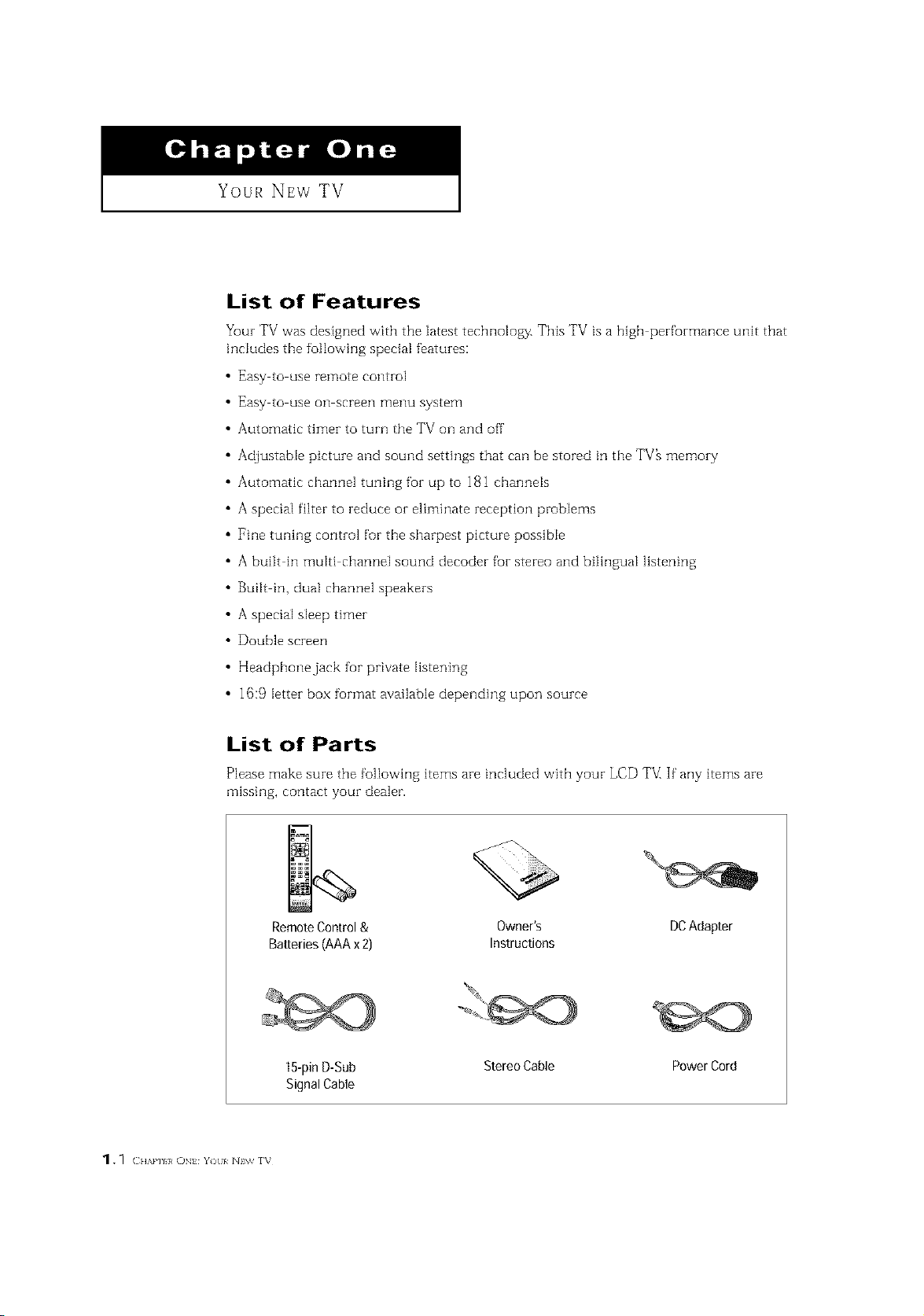
List of Parts
Please make sure the following items are included with your LCD TVIIf"any items are
missing, contact your dealer.
RemoteControl& Owner's DCAdapter
Batteries(AAAx2) Instructions
15-pinD-Sub StereoCable PowerCord
SignalCable
1. _ ( HAm I, ON Y)[I/ N\v rv
I Your NEw TV
Familiarizing Yourself with The TV
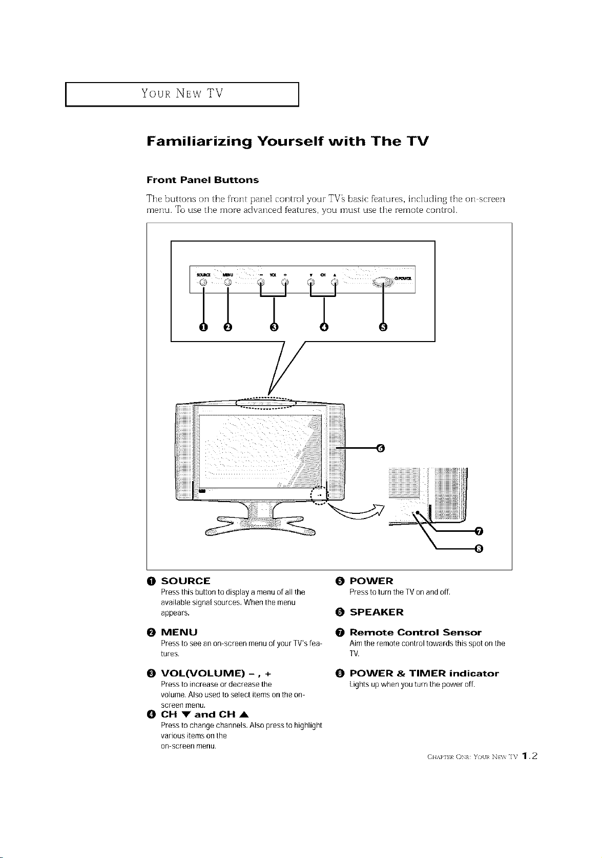
Front Panel Buttons
The buttons on the front pane[ control your TV_ basic f_atures, hldudhlg the on screen
menu. To use the more advanced f_atures, you must use the remote control.
LTT
/
(0 SOURCE
Pressthisbuttontodisplayamenu ofallthe
available signal sources. When the menu
appears,
0 MENU
Press to see an on screen menu of your ]V's lea
tures,
O VOL(VOLUME) -0 +
Press to increase or decrease the
volume, Also used to select items on the on
screen menu,
0 CH VandCHA
Press to change channels. Also press to highlight
various items on the
on screen menu.
0 POWER
Press to turn the TVon and off,
O SPEAKER
Remote Control Sensor
Aim the remote control towards this spot on the
TV.
O POWER & TIMER indicator
Lightsupwhenyouturnthepoweroff.
(2HAP] k ON YO/[< NEV_ ]V 1.2
Your NEw TV ]
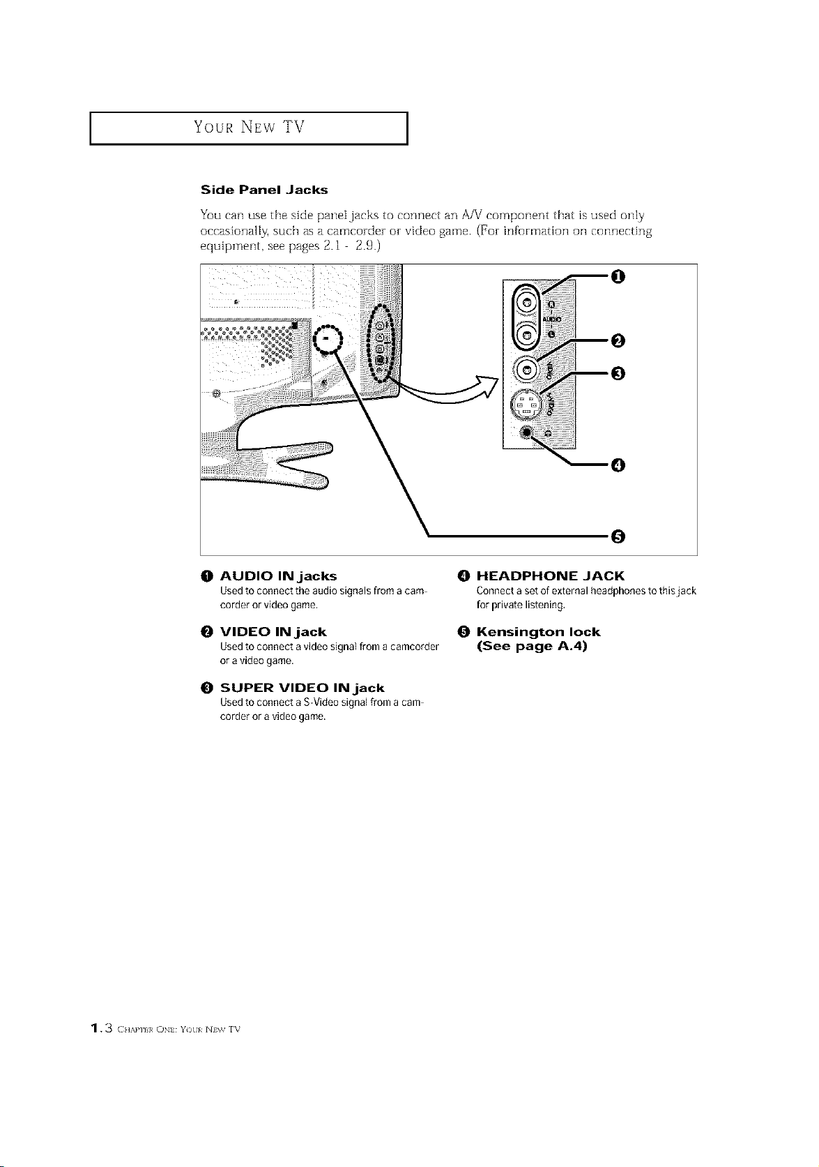
Side Panel Jacks
You can use the side panei jacks to connect an A/V component that is used only
occasionally, such as a camcozdez or video game. (For information oil connecting
equipment, see pages 2.1 2.9.)
0
0
O AUDIO INjacks
Used to connect the audio signals from a cam
corder or video game.
O VIDEO INjack
Used to connect a video signal [rom a camcorder
or a video game.
0 SUPER VIDEO INjack
Used to connect a S-Video signal from a cam
corder or a video game.
HEADPHONE JACK
Connect a set of external headphones to thisjack
for private listening.
Kensington lock
(See page A.4)
1.3 CH',.P] }, ON Y)tl/ N\_ rv
Your NEw TV ]
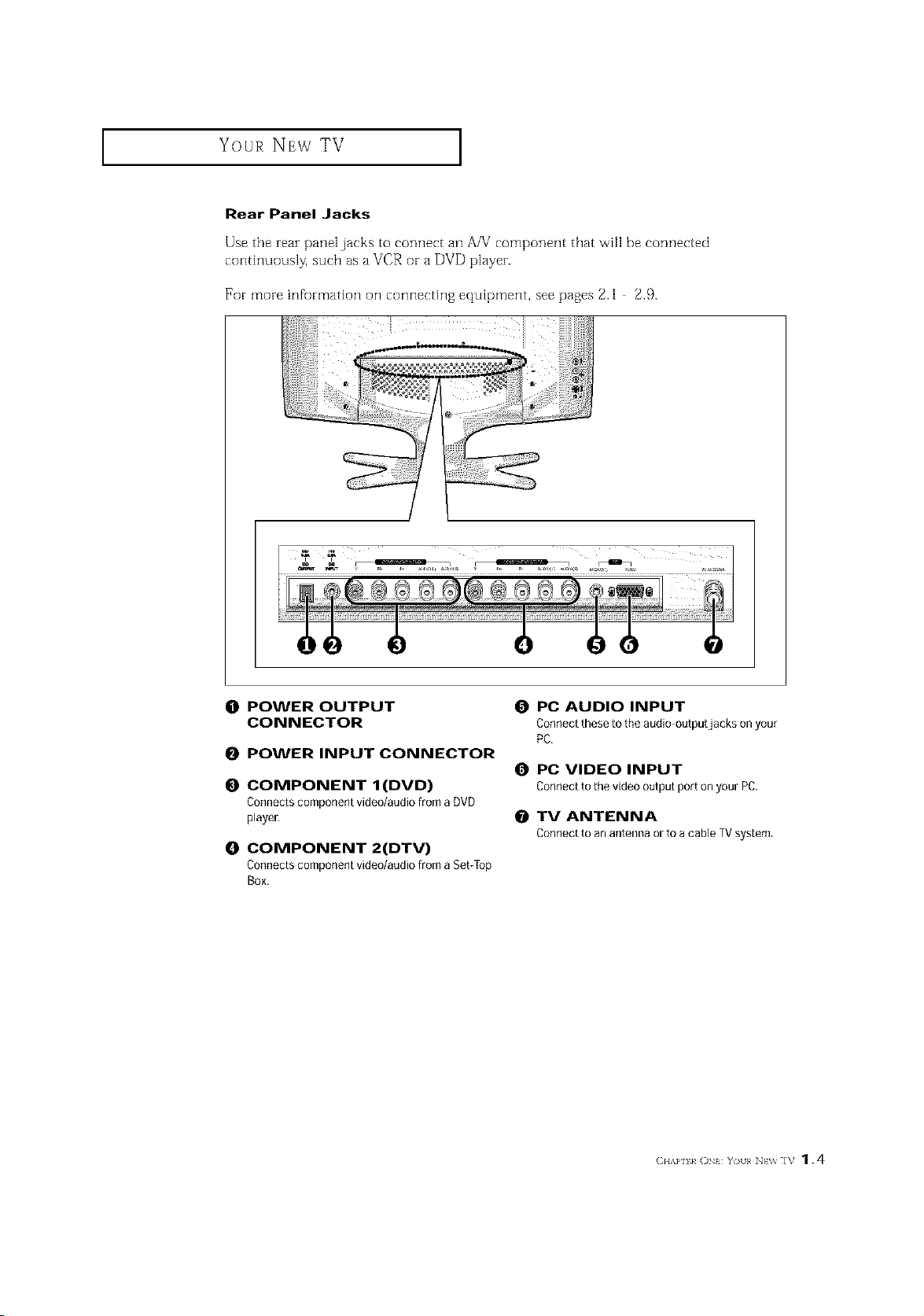
Rear Panel Jacks
Use the rear panel jacks to connect an A/V component that _viHbe connected
conth]uously, such asa VCR or a DVD player.
For more infurmation on connecting equipment, see pages 2.1 2.9.
(]1 POWER OUTPUT
CONNECTOR
0 POWER INPUT CONNECTOR
O COMPONENT I(DVD)
Connects component video/audio from a DVD
player,
O COMPONENT 2(DTV)
Connects component video/audio from a Set/fop
Box.
O PC AUDIO INPUT
Connect these to the audio outputjacks on your
PC.
0 PC VIDEO INPUT
Connectto thevideooutputportonyourPC.
O TV ANTENNA
Connectto anantennaorto acableTVsystem.
(2HAP] 1, ()N YOII< NEV_ ]V 1.4
Your NEw TV I
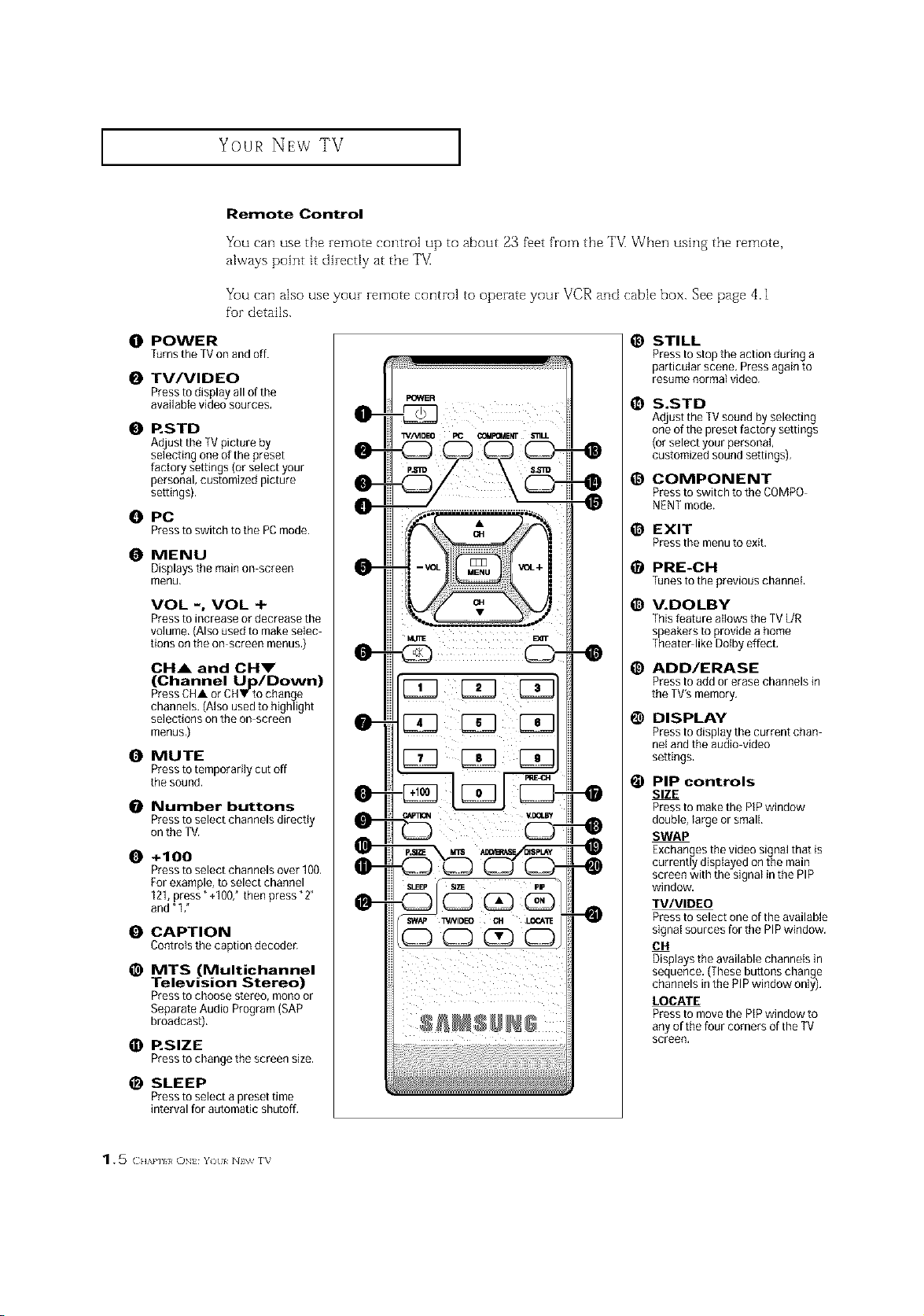
Remote Control
You can use the remote control up to about 23 fi_et from the "FV_When ushlg the remote,
always point it direcdy at the TV
You can also use your remote control to operate your VCR and cable box. See page 4.1
for details.
O POWER
TurnstheTVonandoff.
O TV/VIDEO
Pressto display all of the
available video sources.
0 RSTD
A_usttheTV picture by
selecting one ofthe preset
Nctoq se_ings(orselectyour
personal, cus_mized picture
sewings).
O PC
Presstoswitchtothe PCmode.
O MENU
Displays the main on screen
menu,
VOL -, VOL +
Press to increase or decrease the
volume,(Alsoused to make selec
lions on the on-screen menus,)
CH& and OHm"
(Channel Up/Down)
Press CHA or CHV to change
channeJs.(Also used to highlight
selections on the on screen
menus,)
O MUTE
Press totemporarily cut off
the sound.
0 Number buttons
Pressto select channels directly
on the TV.
O +100
Press to select channels over 100.
For example, to select channel
121,press" +1007 then press "2"
and"1 ,"
O CAPTION
Controls the caption decoder,
_) MTS (Multichannel
Television Stereo)
Pressto choose stereo, mono or
Separate Audio Program (SAP
broadcast).
O RSlZE
Presstochangethescreensize,
_) SLEEP
Press to select a preset time
interval for automatic shutoff,
_) STILL
Press to stop the action during a
particular scene, Pressagain 1o
resume normal video.
1_ S.STD
Adjustthe TVsound by selectillg
one of the preset factory settings
(or select yourpersonal,
customized sound settings),
@ COMPONENT
Press to switch to the COMPO-
NENT mode.
_) EXIT
Press the menu to exit.
_) PRE-CH
Tunes to the previous channel,
_) V.DOLBY
This feature allows the TV L/R
speakers to provide a home
Theater like Dotby effect.
_) ADD/ERASE
Press to add or erase channels in
the TV's memory.
1_ DISPLAY
Pressto display the current chan
nel and the audio-video
settings.
@ PIP controls
SIZE
Pressto make the PiPwindow
double, large or small,
SWAP
Exchanges the video signal that is
currently displayed on the main
screen with the signal in the PIP
window.
TV/VIDEO
Pressto select one of the available
signatsources for the PIPwindow.
014
Displays the available channels in
sequence. (Thesebuttons change
channels inthe PiP window only),
LOCATE
Pressto move the PIPwindow to
any of the four corners of the TV
screen.
1. 5 () tzkl'/I}/ ()N Y) I/ NIW f_
INSTALLATION
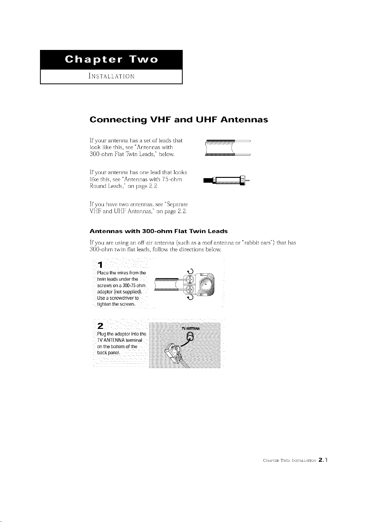
Connecting VHF and UHF Antennas
If your antenna has a set of leads that
look like this, see "Antennas with
3OO ohm Flat 7_vin Leads," below.
If your antenna has one lead that looks
like this, see "Antennas with 75 ohm
Round Leads," oil page 2.2.
If you have two antennas, see "Separate
VHF and UHF Antennas," oil page 2.2.
Antennas with 300-ohm Flat Twin Leads
If"you are using an off air antenna (such as a roof antenna or "rabbit ears") that has
300-ohm twin fiat leads, follow the directions below'.
1
Place the wires from the
[wm eaas under the
screws on a 300J5 ohm
adaptor Inot suppltedl,
use a screwdriver to
ugeten me screws
2
Plugtheadaptorintothe
TVANTENNAterminat
onthebottomofthe
backpanel
INSTALLATION ]
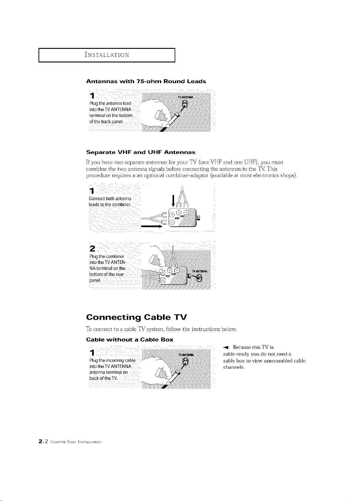
Antennas with 75-ohm Round Leads
1
Plug the antenna tead
into theTV ANTENNA
terminal on the bottom
of the back panel.
Separate VHF and UHF Antennas
If' you have two separate antennas for your TV (one VH1_and one UHF), you must
combine the tVMOanterula signa]s before connecting the antennas to the TV This
procedure requires a an optional combiner adaptor (avaiiab[e at most electronics shops).
Connect both antenna
leads to the combiner,
z -4
Plug the combiner
into theTV ANTEN-
NA terminal on the
botton"
panel
Connecting Cable TV
To connect to a cable TV system, follow the instructioi]s below.
Cable without a Cable Box
1
Plug the incoming cable
into the TV ANTENNA
antenna terminal on
back ofthe TV,
-411 Because this TV is
table-read Z you do not need a
cable box to view unscrambled cable
channels.
2.2 ( H,,,m]_}a i_s],_=] A]JO_
INSTALLATION ]
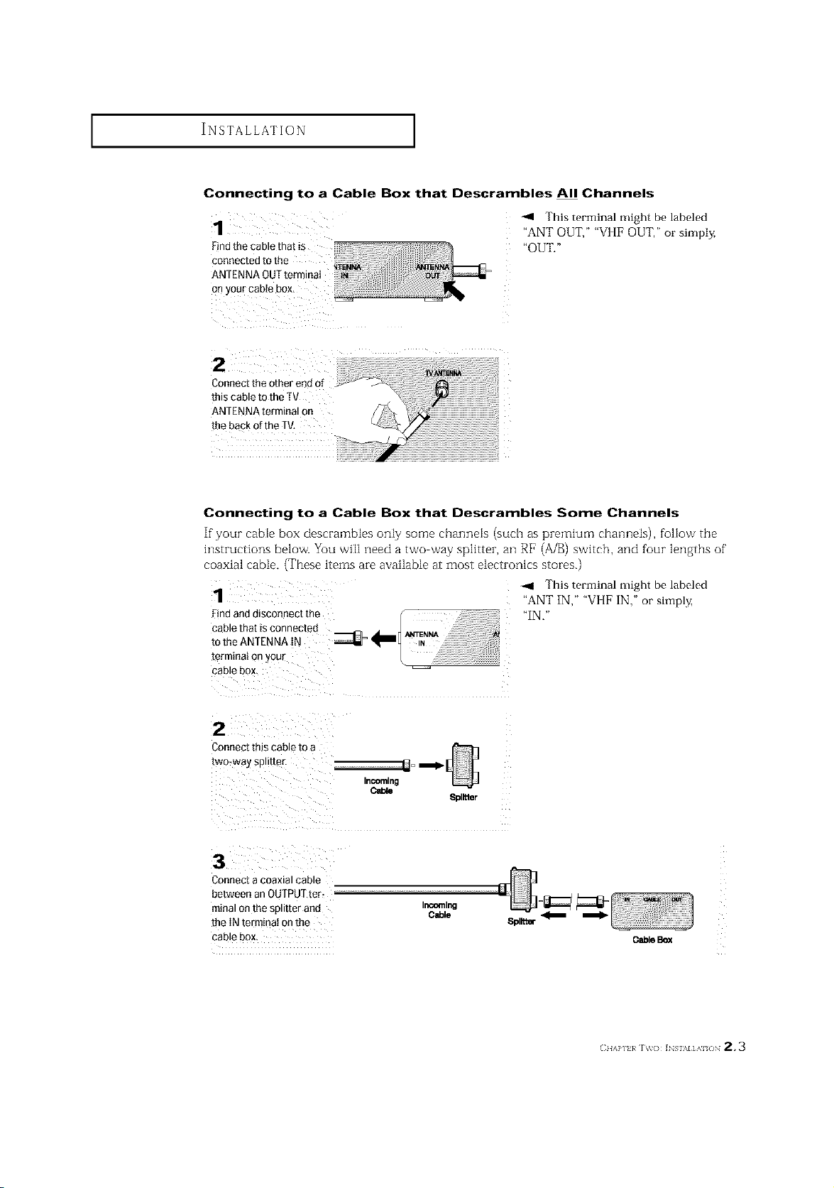
Connecting to a Cable Box that Descrambles All Channels
1
Findthecablethat is
This terminal might be labeled
"ANT OUT," "VI [F OUT," or simply,
"OUT."
cooneotedtothe ) _
ANTflNNAOUTtermmat
onyourcab ebox
2 :
Connecttheotherendof
thiscableto theTV
ANTENNAterminalon
thebackoftheTV,
Connecting to a Cable Box that Descrambles Some Channels
If"your cable box descrambles only some charmeis (such as premium channels), follow the
instructions below. You will need a two way splitter, an RF (A/B) switch, and four lengths of"
coaxial cable. (These items are available at most electronics stores.)
1
-ql This terminal might be labeled
"ANT IN," "VI [F IN," or simply,
"IN,"
[erminai on your
cable box.
2
Connec[ IRIS cable m a
[wo_waysp.[[e£
InCOming
3
Connect a coaxial cable
between an OUFPUTter_ --
minal on the splitter and Ir_emlng
[he IN term_na_on me
cable box.
Cable
8pl_ter
Spllt_
O_le Box
(_IIAP] }/ IV(} ]NSIM]AI /IN 2.3
INSTALLATION ]
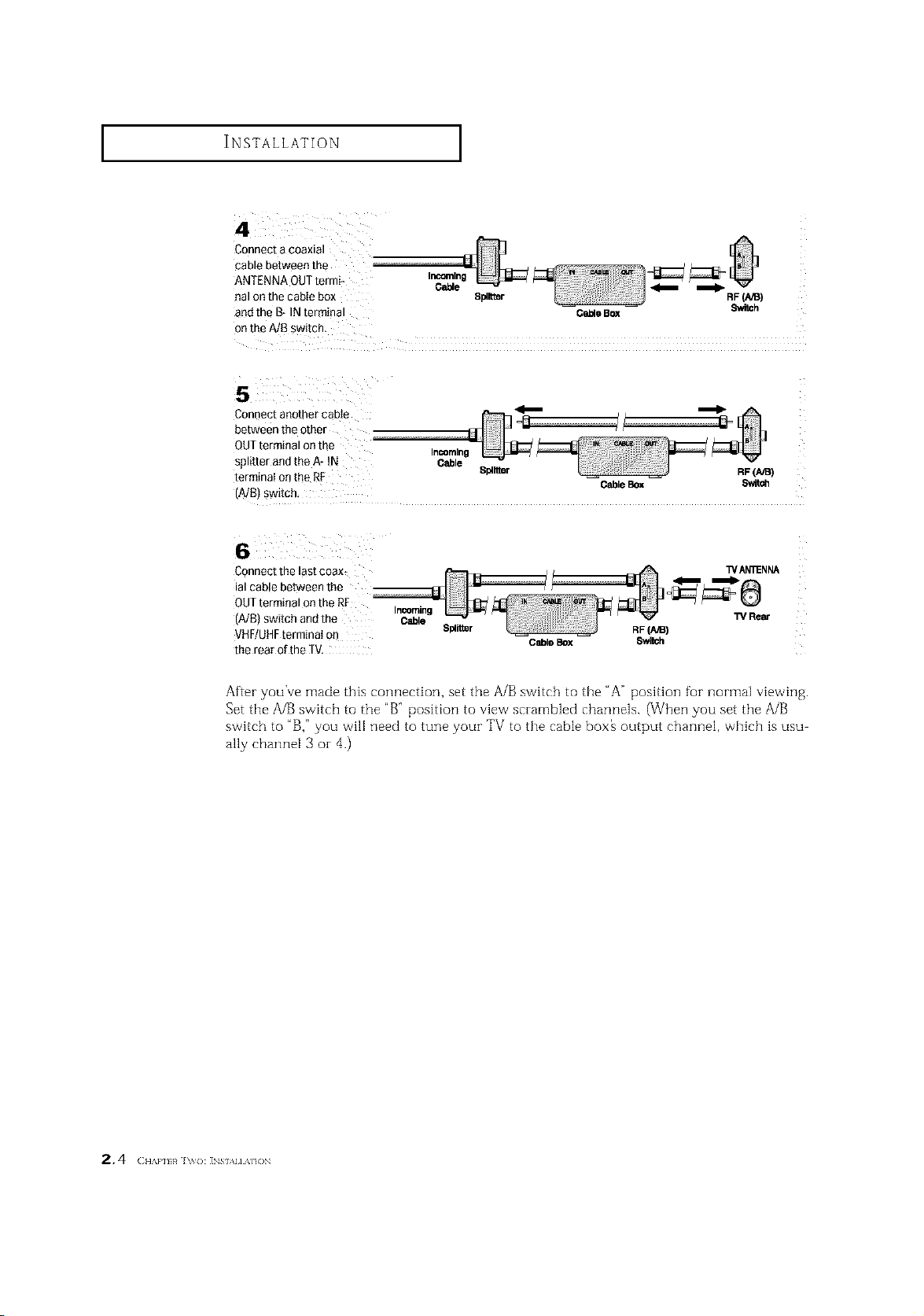
Connect a coaxial
cable between the
ANTENNA QUTtermi- Incoming
eal on the cabIe box Splitter RF(A,_)
and the B- IN terminal O_e Box Switch
onthe A/B switch.
Connect another cable _ _
between the other
QUTterminal on the
splitter andthe A- tN Cable
terminaI onthe RF Spllrmr RF(AIB)
(A/B) Switch,
Connect the last coax_ WAN'_NNA
ial cable between the
OUTterminal on the RF
(A/B) switch and the Cable W Rear
VHF/UHFterminal on Splil_r RF(AiB)
the rear of the TV,
Cable _
Incoming
CableBox $wit_
Incoming
CableBox 8witch
After you've made this connection, set the A/B switch to the "A" position fur normal viewing.
Set tile A/B switch to the "B" position to view scrambled channels. (When you set tile A/B
switch to "B," you will need to tune your TV to tile cable box_ output channel, which is usu
ally channel 3 oi- 4.)
2, 4 (:,,.,,,,,,,,_],_{):INs,,,,,A,.).
INSTALLATION ]
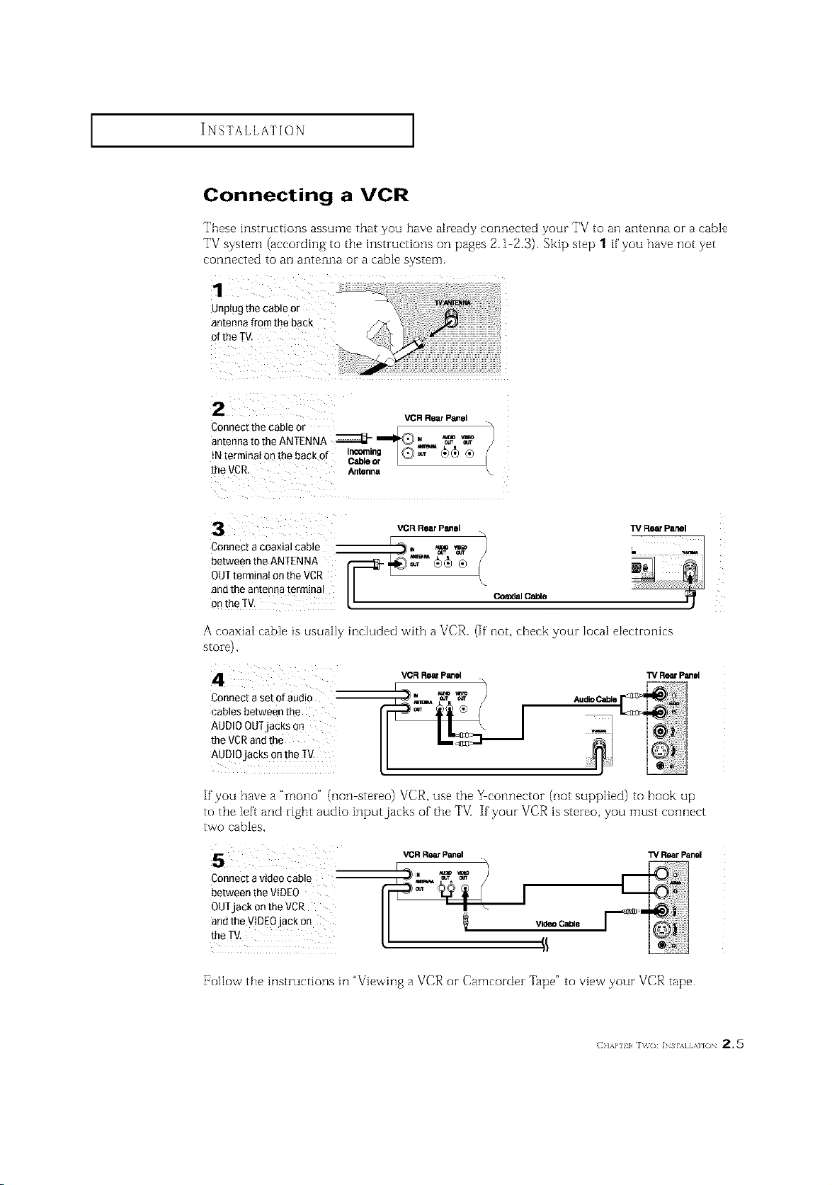
Connecting a VCR
These instructions assume that you have already connected your TV to an antenna or a cable
TV system (according to the instructions on pages 2.1 2.3). Skip step 1 if'you have not yet
connected to an antenna or a cable system.
1
Unplugthecableor
antennafromtheback
ofthe TV.
2
Connect the cable or _[ _. _/
VGR Rear Panel
antennatotheANTENNA ZZZZ_=_,_ _
{Nterrninatanthebackof ICr_le'_ [Q)_ _)_ ®
[heVCR. Antenna
3
Connect a coaxial cable
between the ANTENNA
OUTterminal on the VCR
ana Tneantenna termina
onthe IV.
VCR Rear Panel
A coaxial cabIe is usually inciuded with a VCR.
_lal Cable
If' not, check your IocaI eiectmnlcs
TV Rear Panel
i !'!#',!ii!i! ! , !i,,iiii!iiiii,ii! iii i!i iii illii
stoTe),
Connect a set ofaudio
cables between the
AUDIOOUTjacks On
the VCRand the
AUDIOjacks on the IV.
_RR_P_el
_1
1_/ReefPanel
If you have a "mono" (non stereo) VCR, use the _eonnector (not supplied) to hook up
to the [eft and right audio inputjacks of the TV[ If your VCR is stereo, you must connect
tVVOcables,
VOR R_lr Panel
Connect a video cable
between the VIDEO
OUTjack on the VCR
andthe WDEOjack on
the TV,
[7ollow the instructions in "Viewing a VCR or Camcorder Tape" to view your VCR tape.
Video Cabie
(]]'kl'll l r\_o: INs],_] [ ,\]l() 2 * 5
TV RearPanel
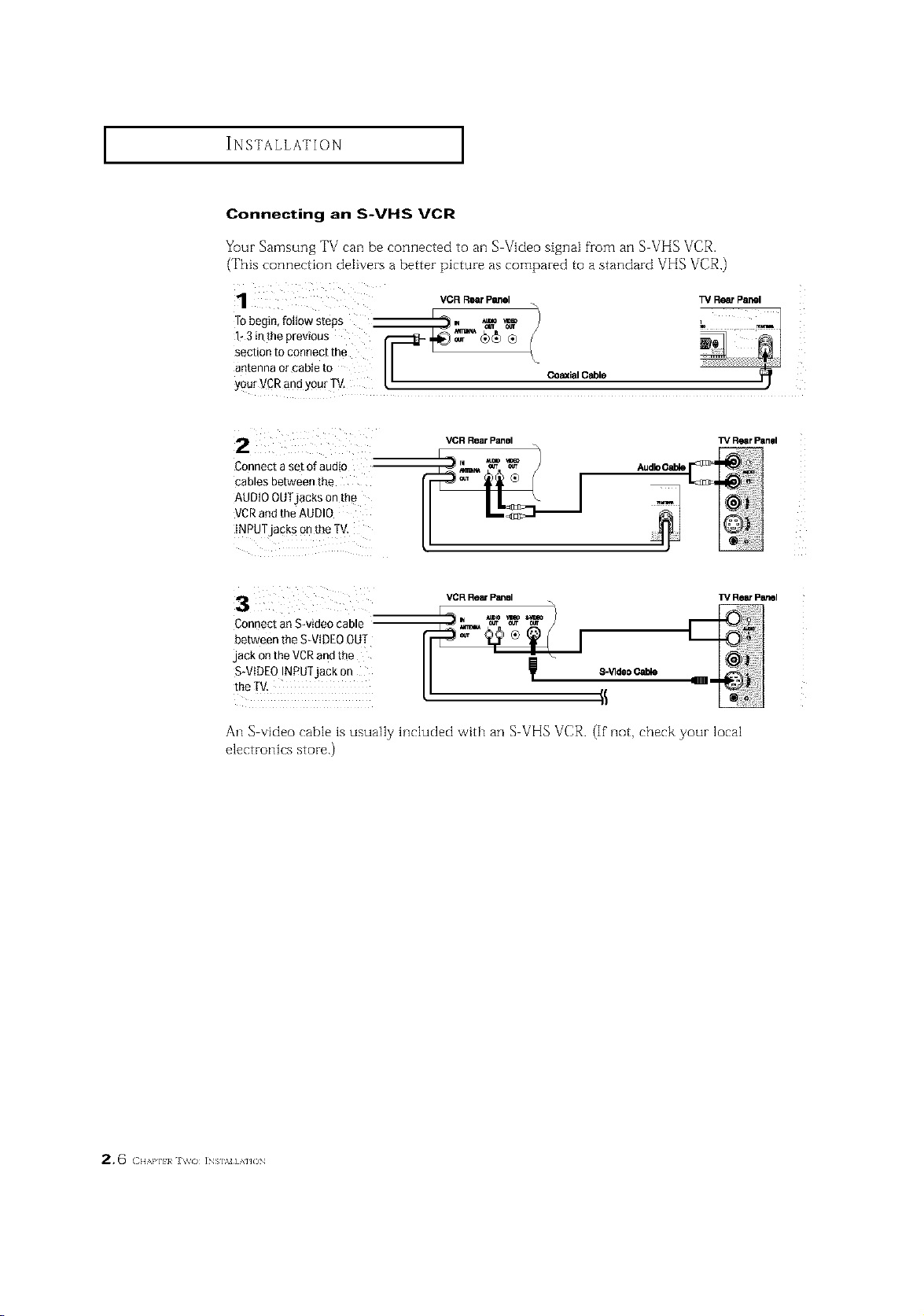
INSTALLATION I
Connecting an S-VHS VCR
Your Samsung TV can be connected to an S-Video signal fronl an S VHS VCR.
(This connection delivers a better picture as compared to a standard VHS VCR.)
R
: VCR_ Panel TVRe_ panel
Tobegin,fottows'teps _m., *_ _ h _ _
g;t 7o17::it,e
antenna or cable to I I co_ial Cable I)
yourVCR and yourTV. 12
TVRearPan01
TV I_ panel
2
Connect a set of audio
cables ee[ween the
AUDIOOUTjacks on me
VCRano [ne AUDIO
INPUTjacks on me IV
V(_R RlSar Panel
VCR Rein P_sl
3
2onnec[ an Swmeo came
aetween the S-VIDEOOUT
jack Onthe VCRand the
S-VIDEOINPU]jac_ o_
me IV.
An S-video -able is usually htcluded with an S VHS VCR. (If not, check your local
electrott[cs store.)
8-Vide0Cable
2,6 ( ],,,,},][:!}_ J \tv<) ]NS],M] A']JON
INSTALLATION ]
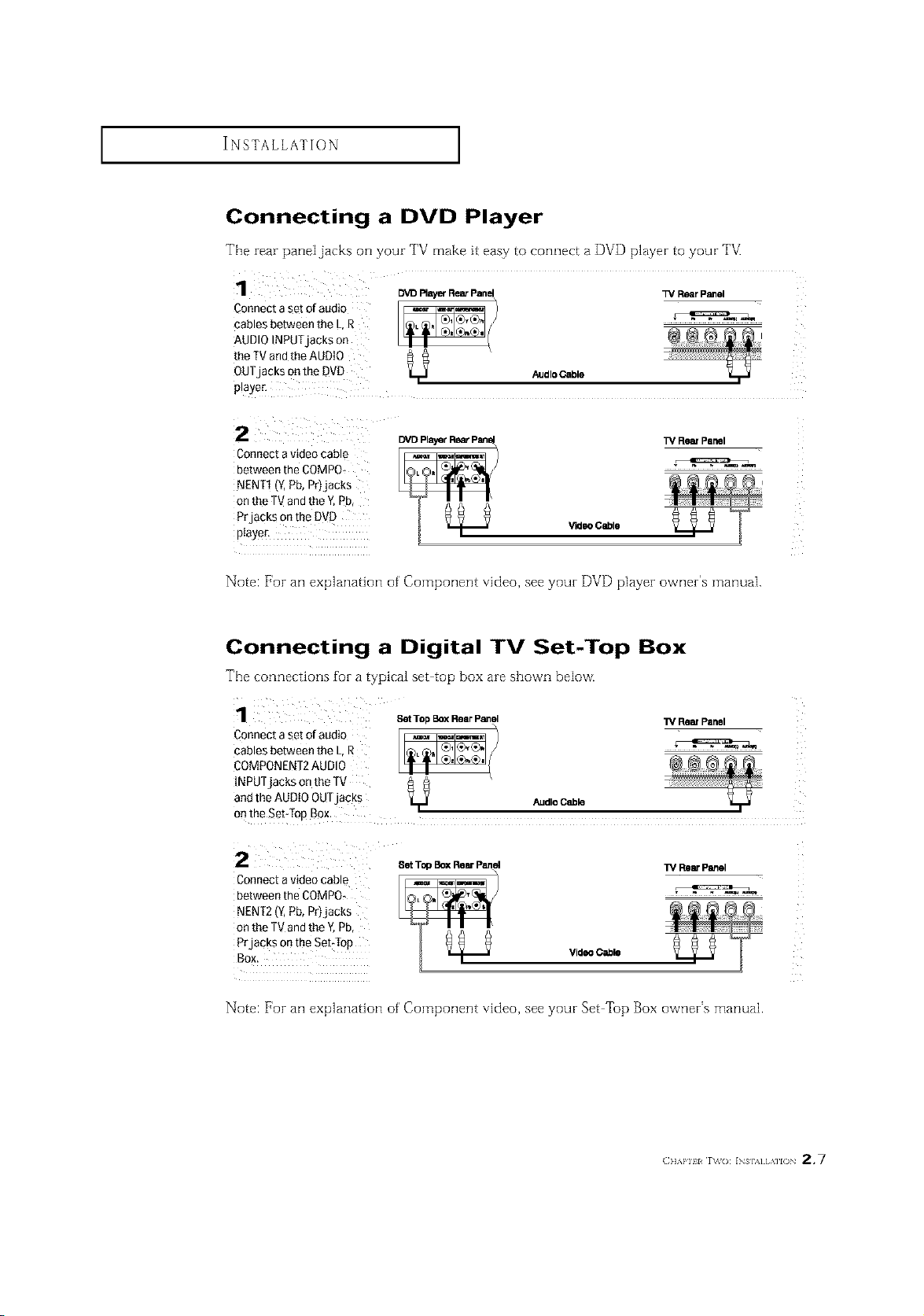
Connecting a DVD Player
The rear paneljacks on your TV make it easy to connect a DVD player to your TV.
Connect a set of audio
cables between the L.R
AUDIO INPUTjacKs on
the TV and the AUDIO
OUT acksonthe DVD
3_aye£
2
Connect avideo cable
between the COMPO+
NENT1 'Z Pb, Pr_jac_s
on the TV and the _ Pb
PrjacKs on me DVC
pla_.er.
DVD Ray_ RearPane_ _/Rear Panel
AudloOable
TV Rear Panel
VideoCable
Note: For an explanation of' Component video, see your DVD player owner's manual.
Connecting a Digital TV Set-Top Box
The connections for a typical set top box are shown below.
Connect a set of audio
SetTop BoxRear Panel
cables between the L,R
COMPONENT2AUDIO
INPUTjacks onthe TV
and the AUDIO OUTjacks AudleCable
onthe Set:lop Box.
1_ ReinPanel
2 SetTopBOXRearPanel
Connect avideo cable
between the COMPO,
NENT2 (Y,Pb, Pr)jacks
on the TVand the Y,Pb,
Prjacks onthe SebTop
Video Cable
TM RearPanel
Note: For an explanation of' Component video, see your Set Top Box owner's manual.
(}]]'kl'll l r\_o: INs],,][,\]l() 2.7
INSTALLATION ]
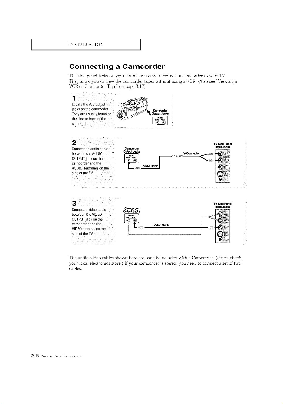
Connecting a Camcorder
The side panel jacks o1-1your TV make it easy to connect a carncorder to your TM
They allow you to vievvrthe camcorder tapes without using a VCR. (Also see "Viewil]g a
VCR or Camcorder Tape" on page 3.17)
1
LocatetheA/Voutput _Jl_
jacks onthecamcorder, _...J.4_ _"__'_'_'>_ _ _ Ceencorder
Theyare usuallyfoundon _S_=J'_,O_P.t Jeal_
t2,2o?rr.hacko",o
W Side Panel
Connect an audio cabIe O.rr_o_ler
0UTPUTjack on the
cameorder andthe
between the AUDt0 _A_
AUDIO terminals onthe
side of the TV,
Output Jecks
Inp=JtJacks
3 ¸
Connecta videocable
_rder
W SidePanel
InputJ_ks
betweenthe VIDEO
OUTPUTjack onthe
cameorderandthe
VIDEOterminalonthe
sideoftheTV,
Tile audio video cables shown here are usually included w'ith a Camcorder. (If' not, check
your local electronics store.) If your camcorder is stereo, you need to connect a set of"two
cables.
2.8 c,,,,,,,,,,,,J,_o INS],NHAHON
INSTALLATION ]
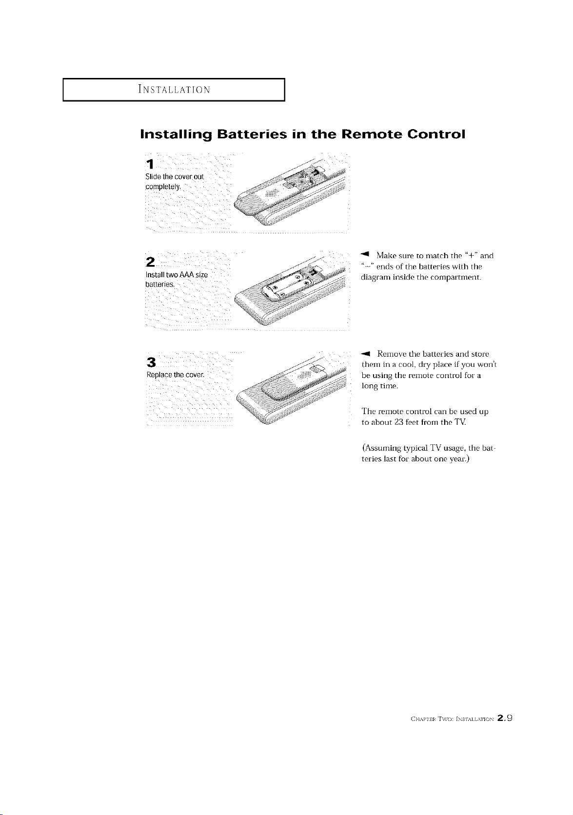
Installing Batteries in the Remote Control
Make sure to match the "+" and
Install tw0 AAA size
batteries_
Replace the cover.
"-" ends of the batteries with the
diagram inside the compartment.
-.11 Remove the batteries and store
them in a cool, dry place if you won't
be using the remote control for a
long time.
The remote control can be used up
to about 23 feet from the TM
(Assuming typical TV usage, the bat-
teries last for about one year.)
(]]_,l'll l r\_(): INs],_][,\]l() 2.9
 Loading...