

Page 1
LED Monitor
Chassis : WVN2
Model : T19C300**
Chassis : WFB2
Model : T22C300**
T24C300**
SERVICE
LED Monitor Contents
1. Precautions
2. Product specications
3. Disassembly and Reassembly
4. Troubleshooting
5. Wiring Diagram
Manual
LT**C300**
Page 2

Contents
1. Precautions ...................................................................................................................1-1
1-1. Safety Precautions ..............................................................................................................1-1
1-1-1. Warnings .......................................................................................................................1-1
1-1-2. Servicing the LED Monitor ............................................................................................1-1
1-1-3. Fire and Shock Hazard .................................................................................................1-1
1-1-4. Product Safety Notices .................................................................................................1-1
1-2. Servicing Precautions ..........................................................................................................1-2
1-2-1. General Servicing Precautions .....................................................................................1-2
1-3. Static Electricity Precautions ...............................................................................................1-3
1-4. Installation Precautions .......................................................................................................1-4
2. Product specications .................................................................................................2-1
2-1. Model Comparison ..............................................................................................................2-1
2-2. Feature & Specications ......................................................................................................2-2
2-2-1. Feature ..........................................................................................................................2-2
2-2-2. Specications ................................................................................................................2-3
2-3. Specication Comparison to Old Models.............................................................................2-6
2-4. Detail Factory Option ........................................................................................................... 2-7
2-5. Accessories .........................................................................................................................2-8
3. Disassembly and Reassembly ....................................................................................3-1
3-1. Disassembly and Reassembly ............................................................................................3-1
4. Troubleshooting ...........................................................................................................4-1
4-1. Previous check ....................................................................................................................4-1
4-2. How to check fault symptom ................................................................................................4-2
4-2-1. No Power ......................................................................................................................4-2
4-2-2. No video (Analog PC signal) .........................................................................................4-4
4-2-3. No video (HDMI1 - Digital signal) ..................................................................................4-7
4-2-4. No video (Tuner_CVBS) .............................................................................................4-10
4-2-5. No video (Tuner DTV) .................................................................................................4-14
4-2-6. No video (Video CVBS) ..............................................................................................4-18
4-2-7. No video (Component) ................................................................................................4-22
4-2-8. No sound .....................................................................................................................4-25
4-4. Adjustment .........................................................................................................................4-28
4-4-1. Service Instruction ......................................................................................................4-28
4-4-2. How to Access Service Mode .....................................................................................4-28
4-4-3. Service Mode Menu ....................................................................................................4-29
4-4-4. White Balance - Calibration ........................................................................................4-41
4-4-5. White Balance - Adjustment ........................................................................................4-43
4-5. Software Upgrade ..............................................................................................................4-45
4-5-1. How to check the SW version .....................................................................................4-45
4-5-2. How to Upgade SW and Micom ..................................................................................4-47
5. Wiring Diagram .............................................................................................................5-1
5-1. Wiring Diagram .................................................................................................................... 5-1
5-2. Board Connection ................................................................................................................ 5-2
5-3. Connector Functions ...........................................................................................................5-4
5-4. Cables .................................................................................................................................5-4
A. Exploded View & Part List [TC300] ........................................................................... A-1
A-1. Exploded View ................................................................................................................... A-1
A-1-1. Parts List (T19C300**) ................................................................................................. A-2
Page 3

A-1-2. Electrical Parts List (T19C300**) ................................................................................. A-2
A-2-1. Parts List (T22C300**) ................................................................................................. A-5
A-2-2. Electrical Parts List (T22C300**) ................................................................................. A-5
A-3-1. Parts List (T24C300**) ................................................................................................. A-8
A-3-2. Electrical Parts List (T24C300**) ................................................................................. A-8
Page 4

This Service Manual is a property of Samsung Electronics Co.,Ltd.
Any unauthorized use of Manual can be punished under applicable
International and/or domestic law.
© 2013 Samsung Electronics Co.,Ltd. All
rights reserved.
Printed in Korea
Page 5
3. Disassembly and Reassemble
3. Disassembly and Reassembly
This section of the service manual describes the disassembly and reassembly procedures for the Monitor.
As this monitor has parts that are sensitive to static electricity, be careful when handling them.
WARNING
3-1. Disassembly and Reassembly
Turn the monitor off before beginning the disassembly process.1.
When disassembling the monitor, do not use any metal tools except for the provided jig.2.
CAUTION
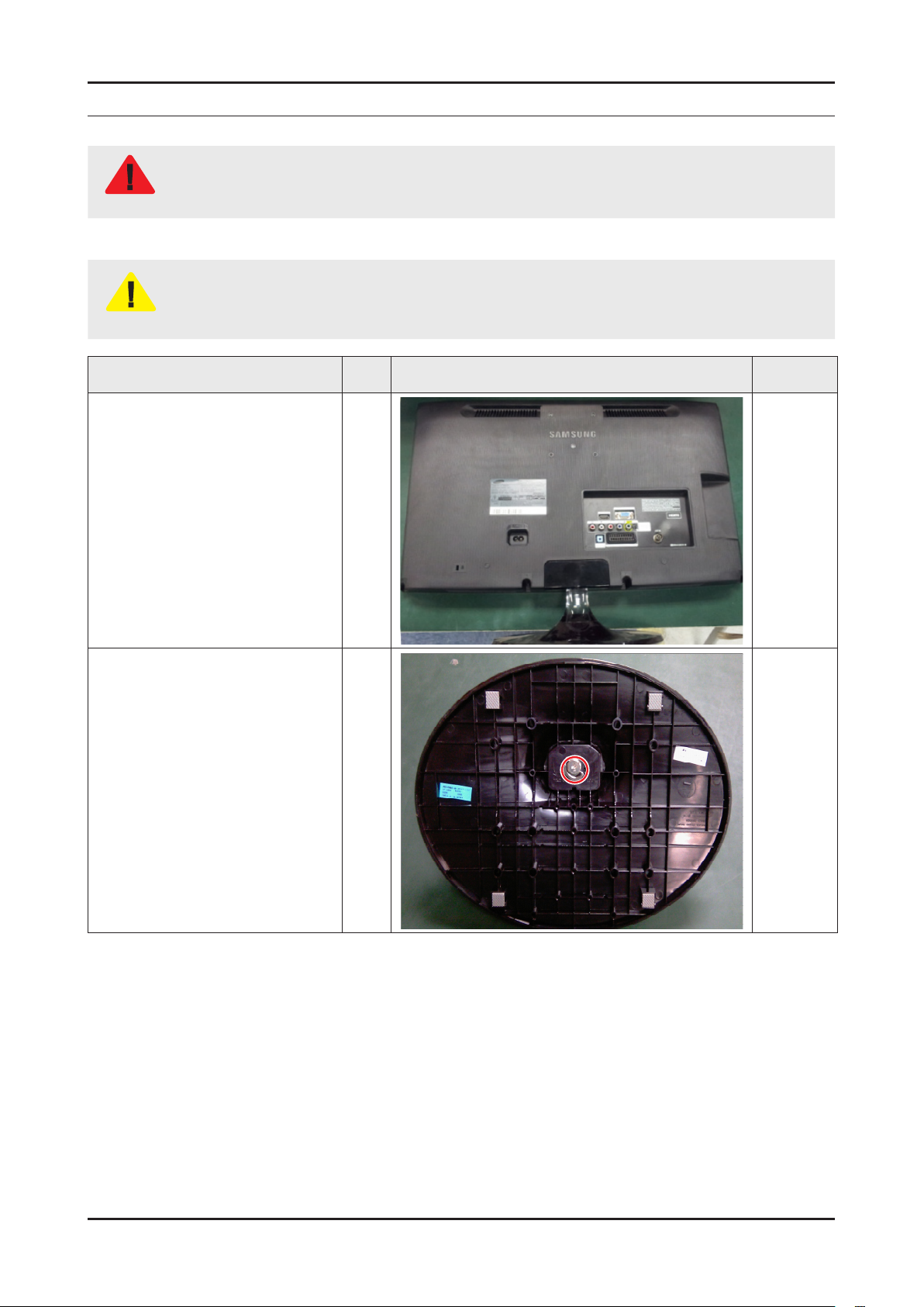
Place monitor face down on
1
cushioned table.
Disassemble the monitor carefully as directed in the following procedures.3.
Description Inch Picture Description Screws
Remove single screw from the
2
stand.
All
All
3-1
Page 6

3-2
3. Disassembly and Reassemble
3-3
3. Disassembly and Reassemble
Description Inch Picture Description Screws
Remove 4 screws from the rear-
3
cover.
Remove 3 screws from the rearcover.
21.5"
24"
18.5"
6003-001086
Remove the one screw in
4
interface area.
18.5"
21.5"
24"
6003-001782
Page 7
Description Inch Picture Description Screws
3-3
3. Disassembly and Reassemble
3-3
3. Disassembly and Reassemble
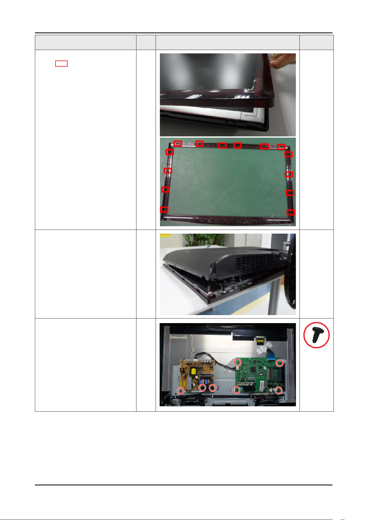
Detach the front from monitor.
5
: locking point (14 point)
All
Lift up the rear-cover.
6
Remove the 4 screws of main
7
board and 3 screws SMPS
board.
All
6003-000115
All
Page 8

3-4
3. Disassembly and Reassemble
3-5
3. Disassembly and Reassemble
Description Inch Picture Description Screws
Remove the left and right
8
speaker.
Remove the panel bracket.
9
All
All
Lift up the panel bracket.
10
Lift up the panel.
11
: locking point
All
All
Page 9

How to disassembly Function & IR ASSY
3-5
3. Disassembly and Reassemble
3-5
3. Disassembly and Reassemble
Description Inch Picture Description Screws
There is no clip.
1
Heat the Function Assy by Heat
2
Gun and Lift up the Function
Assy.
All
All
NOTE
Reassembly procedures are in the reverse order of disassembly procedures.
Page 10
1. Precautions
1-1. Safety Precautions
Follow these safety, servicing and ESD precautions to prevent damage and to protect against potential hazards such as
electrical shock.
1-1-1. Warnings
For continued safety, do not attempt to modify the circuit board.
WARNING
1-1-2. Servicing the LED Monitor
When servicing the LED Monitor, Disconnect the AC line cord from the AC outlet.1.
It is essential that service technicians have an accurate voltage meter available at all times. Check the calibration of this 2.
meter periodically.
1-1-3. Fire and Shock Hazard
Before returning the monitor to the user, perform the following safety checks:
Inspect each lead dress to make certain that the leads are not pinched or that hardware is not lodged between the chassis 1.
and other metal parts in the monitor.
Inspect all protective devices such as nonmetallic control knobs, insulating materials, cabinet backs, adjustment and 2.
compartment covers or shields, isolation resistorcapacitor networks, mechanical insulators, etc.
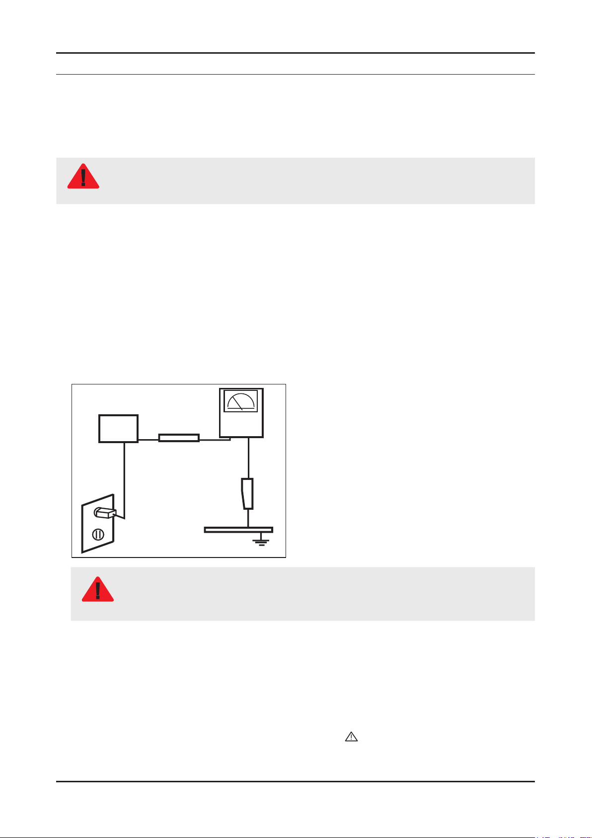
Leakage Current Hot Check:3.
Disconnect the AC power and DC power jack before servicing.
(READING SHOULD)
DEVICE
UNDER
TEST
ALSO TEST WITH PLUG
REVERSED (USING AC
ADAPTER PLUG AS
REQUIRED)
NOT BE ABOVE 0.5mA
EXPOSED METAL
2-WIRE CORD
TEST ALL
SURFACES
LEAKAGE
CURRENT
TESTER
EARTH
GROUND
Do not use an isolation transformer during this test.
Use a leakage current tester or a metering system that complies with American National Standards
WARNING
Institute (ANSI C101.1, Leakage Current for Appliances), and Underwriters Laboratories (UL Publication
UL1410, 59.7).
With the unit completely reassembled, plug the AC line cord directly into a 120V AC outlet. With the unit’s AC switch rst in 4.
the ON position and then OFF, measure the current between a known earth ground (metal water pipe, conduit, etc.) and all
exposed metal parts, including: metal cabinets, screwheads and control shafts.
The current measured should not exceed 0.5 milliamp.
Reverse the power-plug prongs in the AC outlet and repeat the test.
1-1-4. Product Safety Notices
Some electrical and mechanical parts have special safetyrelated characteristics which are often not evident from visual
inspection. The protection they give may not be obtained by replacing them with components rated for higher voltage,
wattage, etc. Parts that have special safety characteristics are identied by on schematics and parts lists. A substitute
replacement that does not have the same safety characteristics as the recommended replacement part might create shock,
re and/or other hazards. Product safety is under review continuously and new instructions are issued whenever appropriate.
Page 11

1-2 1-3
1. Precautions 1. Precautions
1-2. Servicing Precautions
An electrolytic capacitor installed with the wrong polarity might explode.
WARNING
Before servicing units covered by this service manual, read and follow the Safety Precautions section of
CAUTION
NOTE
1-2-1. General Servicing Precautions
Always unplug the unit’s AC power cord from the AC power source and disconnect the DC Power Jack before attempting to: 1.
(a) remove or reinstall any component or assembly, (b) disconnect PCB plugs or connectors, (c) connect a test component
in parallel with an electrolytic capacitor.
Some components are raised above the printed circuit board for safety. An insulation tube or tape is sometimes used. The 2.
internal wiring is sometimes clamped to prevent contact with thermally hot components. Reinstall all such elements to their
original position.
After servicing, always check that the screws, components and wiring have been correctly reinstalled. Make sure that the 3.
area around the serviced part has not been damaged.
Check the insulation between the blades of the AC plug and accessible conductive parts (examples: metal panels, input 4.
terminals and earphone jacks).
Insulation Checking Procedure: Disconnect the power cord from the AC source and turn the power switch ON. 5.
Connect an insulation resistance meter (500 V) to theblades of the AC plug.
The insulation resistance between each blade of the AC plug and accessible conductive parts (see above) should be
greater than 1 megohm.
Always connect a test instrument’s ground lead to the instrument chassis ground before connecting the positive lead; 6.
always remove the instrument’s ground lead last.
this manual.
If unforeseen circumstances create conict between the following servicing precautions and any of the
safety precautions, always follow the safety precautions.
Page 12
1-3. Static Electricity Precautions
Some semiconductor (solid state) devices can be easily damaged by static electricity. Such components are commonly
called Electrostatically Sensitive Devices (ESD). Examples of typical ESD are integrated circuits and some eld-effect
transistors. The following techniques will reduce the incidence of component damage caused by static electricity.
Immediately before handling any semiconductor components or assemblies, drain the electrostatic charge from your body 1.
by touching a known earth ground. Alternatively, wear a discharging wrist-strap device. To avoid a shock hazard, be sure to
remove the wrist strap before applying power to the monitor.
After removing an ESD-equipped assembly, place it on a conductive surface such as aluminum foil to prevent accumulation 2.
of an electrostatic charge.
Do not use freon-propelled chemicals. These can generate electrical charges sufcient to damage ESDs.3.
Use only a grounded-tip soldering iron to solder or desolder ESDs.4.
Use only an anti-static solder removal device. Some solder removal devices not classied as “anti-static” can generate 5.
electrical charges sufcient to damage ESDs.
Do not remove a replacement ESD from its protective package until you are ready to install it. Most replacement ESDs are 6.
packaged with leads that are electrically shorted together by conductive foam, aluminum foil or other conductive materials.
Immediately before removing the protective material from the leads of a replacement ESD, touch the protective material to 7.
the chassis or circuit assembly into which the device will be installed.
Be sure no power is applied to the chassis or circuit and observe all other safety precautions.
CAUTION
Minimize body motions when handling unpackaged replacement ESDs. Motions such as brushing clothes together, 8.
or lifting your foot from a carpeted oor can generate enough static electricity to damage an ESD.
Page 13

1. Precautions 1. Precautions
1-4. Installation Precautions
For safety reasons, more than a people are required for carrying the product.1.
Keep the power cord away from any heat emitting devices, as a melted covering may cause re or electric shock.2.
Do not place the product in areas with poor ventilation such as a bookshelf or closet. The increased internal temperature 3.
may cause re.
Bend the external antenna cable when connecting it to the product. This is a measure to protect it from being exposed to 4.
moisture. Otherwise, it may cause a re or electric shock.
Make sure to turn the power off and unplug the power cord from the outlet before repositioning the product. Also check the 5.
antenna cable or the external connectors if they are fully unplugged. Damage to the cord may cause re or electric shock.
Keep the antenna far away from any high-voltage cables and install it rmly. Contact with the highvoltage cable or the 6.
antenna falling over may cause re or electric shock.
When installing the product, leave enough space (0.4m) between the product and the wall for ventilation purposes. 7.
A rise in temperature within the product may cause re.
If an equipment is provided with a replaceable battery, and if replacement by an incorrect type could result in an 8.
explosion (for example, with some lithium batteries), the following applies:
RISK OF EXPLOSION IF BATTERY IS REPLACED BY AN INCORRECT TYPE.
CAUTION
DISPOSE OF USED BATTERIES ACCORDING TO THE INSTRUCTIONS.
1-4 PB
Page 14

2. Product specications
2-1. Model Comparison
Front View
Detail View
2. Product specications
TC300
Front Color Semitransparent Rose Black
Panel Type TN
Internal Memory None
DDR 256 Mbtye
Feature Media Play(MOVIE)
2-1
Page 15

2-2
2. Product specications
2-3
2. Product specications
2-2. Feature & Specications
2-2-1. Feature
RF, 1-HDMI, 1-Component, 1-A/V, 1-USB2.0, D-SUB•
Brightness: 250cd/m•
High Contrast Ratio: 1,000 •
Response Time: 5ms •
Excellent Picture Quality•
Dynamic Contrast •
Automatically detects the input visual signal and adjusts to create optimum contrast. -
Monitor Tuner, HDMI, Stereo, SRS Trusurround support •
Convenience •
The Monitor utilizes the HDMI system to implement perfect digital sound and picture quality. -
2
Page 16

2-3
2. Product specications
2-3
2. Product specications
2-2-2. Specications
Model Name T19C300**
Item Description
LCD Panel 19 inch HD 60Hz
Scanning Frequency Horizontal: 31 kHz ~ 80 kHz (Automatic)
Vertical: 50 Hz ~ 75 Hz (Automatic)
Display Colors 16.7 Million colors
Maximum resolution Horizontal : 1366 Pixels
Vertical : 768 Pixels
Input Signal Analog 0.7 Vp-p ± 5% positive at 75Ω, internally terminated
Input Sync Signal
Maximum Pixel Clock rate 85 MHz
Active Display (Horizontal/Vertical) 409.8 (H) x 230.4 (V) (mm) / 16.1 (H) x 9.1 (V) (inches)
AC power voltage & Frequency AC 90V~240V, 60/50Hz ± 3Hz
Power Consumption Under 35 W(Under 0.5 W, Stand by)
Dimensions
(WxHxD)
Weight With Stand 3.2 (kg) / 7.05 (lbs)
TV System Tuning Frequency Synthesize
Audio Specications MAX Internal Audio Output Power : Each 5W(Left/Right)
Environmental
considerations
With Stand 444.7 x 356.4 x 187 (mm) / 17.5 x 14.0 x 7.4 (inches)
Without Stand 444.7 x 278.2 x 48.5 (mm) / 17.5 x 11.0 x 2.0 (inches)
Without Stand 3.05 (kg) / 6.72 (lbs)
System NTSC, PAL
Sound NTSC, PAL
Operating Operating Temperature : 50°F - 104°F (10°C - 40°C)
H/V Separate, TTL, P. or N.
Equalizer : 5band
Output Frequency
RF : 20 Hz ~ 15.4 kHz•
AV/Componet/HDMI : 20 Hz ~ 20 kHz•
Humidity : 10% - 80 %
Storage Storage Temperature : -4°F - 113°F (-20°C - 45°C)
Humidity : 5% - 95%
Note: Dolby Digital +, Game Mode, Film Mode, Energy Saving
Page 17

2-4
2. Product specications
2-5
2. Product specications
Model Name T22C300**
Item Description
LCD Panel 21.5 inch FHD 60Hz
Scanning Frequency Horizontal: 31 kHz ~ 80 kHz (Automatic)
Vertical: 50 Hz ~ 75 Hz (Automatic)
Display Colors 16.7 Million colors
Maximum resolution Horizontal: 1920 Pixels
Vertical: 1080 Pixels
Input Signal Analog 0.7 Vp-p ± 5% positive at 75Ω, internally terminated
Input Sync Signal
Maximum Pixel Clock rate 85 MHz
Active Display (Horizontal/Vertical) 476.6 (H) x 268.1 (V) (mm) / 18.8 (H) x 10.6 (V) (inches)
AC power voltage & Frequency AC 90V~240V, 60/50Hz ± 3Hz
Power Consumption Under 35 W(Under 0.5 W, Stand by)
Dimensions
(WxHxD)
Weight With Stand 3.95 (kg) / 8.7 (lbs)
TV System Tuning Frequency Synthesize
Audio Specications MAX Internal Audio Output Power : Each 5W(Left/Right)
Environmental
considerations
With Stand
Without Stand 509.7 x 318.2 x 47 (mm) / 20.1 x 12.5 x 1.9 (inches)
Without Stand 3.7 (kg) / 8.16 (lbs)
System NTSC, PAL
Sound NTSC, PAL
Operating Operating Temperature : 50°F - 104°F (10°C - 40°C)
H/V Separate, TTL, P. or N.
509.7 x 396.6 x 195 (mm) / 20.1 x 15.6 x 7.7 (inches)
Equalizer : 5band
Output Frequency
RF : 20 Hz ~ 15.4 kHz•
AV/Componet/HDMI : 20 Hz ~ 20 kHz•
Humidity : 10% - 80 %
Storage Storage Temperature : -4°F - 113°F (-20°C - 45°C)
Humidity : 5% - 95%
Note: Dolby Digital +, Game Mode, Film Mode, Energy Saving
Page 18
2-5
2. Product specications
2-5
2. Product specications
Model Name T24C300**
Item Description
LCD Panel 24 inch FHD 60Hz
Scanning Frequency Horizontal: 31 kHz ~ 80 kHz (Automatic)
Vertical: 50 Hz ~ 75 Hz (Automatic)
Display Colors 16.7 Million colors
Maximum resolution Horizontal: 1920 Pixels
Vertical: 1080 Pixels
Input Signal Analog 0.7 Vp-p ± 5% positive at 75Ω, internally terminated
Input Sync Signal
Maximum Pixel Clock rate 85 MHz
Active Display (Horizontal/Vertical) 531.36 (H) x 298.89 (V) (mm) / 20.92 (H) x 11.77 (V) (inches)
AC power voltage & Frequency AC 90V~240V, 60/50Hz ± 3Hz
Power Consumption Under 40 W(Under 0.5 W, Stand by)
Dimensions
(WxHxD)
Weight With Stand 4.45 (kg) / 9.81 (lbs)
TV System Tuning Frequency Synthesize
Audio Specications MAX Internal Audio Output Power : Each 5W(Left/Right)
Environmental
considerations
With Stand 569.2 x 428 x 195 (mm) / 22.4 x 16.9 x 7.7 (inches)
Without Stand 569.2 x 349.4 x 49 (mm) / 22.4 x 13.8 x 1.9 (inches)
Without Stand 4.15 (kg) / 9.15 (lbs)
System NTSC, PAL
Sound NTSC, PAL
Operating Operating Temperature : 50°F - 104°F (10°C - 40°C)
H/V Separate, TTL, P. or N.
Equalizer : 5band
Output Frequency
RF : 20 Hz ~ 15.4 kHz•
AV/Componet/HDMI : 20 Hz ~ 20 kHz•
Humidity : 10% - 80 %
Storage Storage Temperature : -4°F - 113°F (-20°C - 45°C)
Humidity : 5% - 95%
Note: Dolby Digital +, Game Mode, Film Mode, Energy Saving
Page 19

2-6
2. Product specications
2-7
2. Product specications
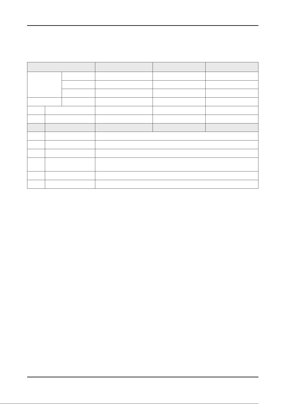
2-3. Specication Comparison to Old Models
O : application, X : non-application
Model
TC300
(T**C300)
TB300 / TB350 / TB530 /TB531
(T**B300 / T**B350 / T**B530/T**B531)
Design
Diplay Type LCD LCD
Built-in Tuner 1 1
Resolution
1920 x 1080 (21.5", 24")
1366 x 768 (18.5")
1920 x 1080 (21.5", 23", 23.6", 24", 27")
1366 x 768 (18.5")
LCD Panel TFT LED PANEL TFT LED PANEL
Screen Size 19" / 22" / 24" 19" / 22" / 23" / 23.6" / 24" / 27"
Picture ratio 16:9 16:9
Brightness 250 cd/m
2
250 cd/m
2
Contrast Ratio 1,000 1,000
Picture Enhancer HyperReal Engine (X9) HyperReal Engine (X9)
Equalizer 5 Band 5 Band
Auto Volume Control O O
Surround Sound Dolby Digital Plus/Pulse Dolby Digital Plus/Pulse
Speaker Output 5W X 5W 5W X 5W
PIP O O
Double Window O O
Caption O O
Entertainment Mode X X
Game Mode O O
Energy Saving O O
Anynet+ X X
Antenna 1(Cable/Air) 1(Cable/Air)
Page 20
2-7
2. Product specications
2-7
2. Product specications
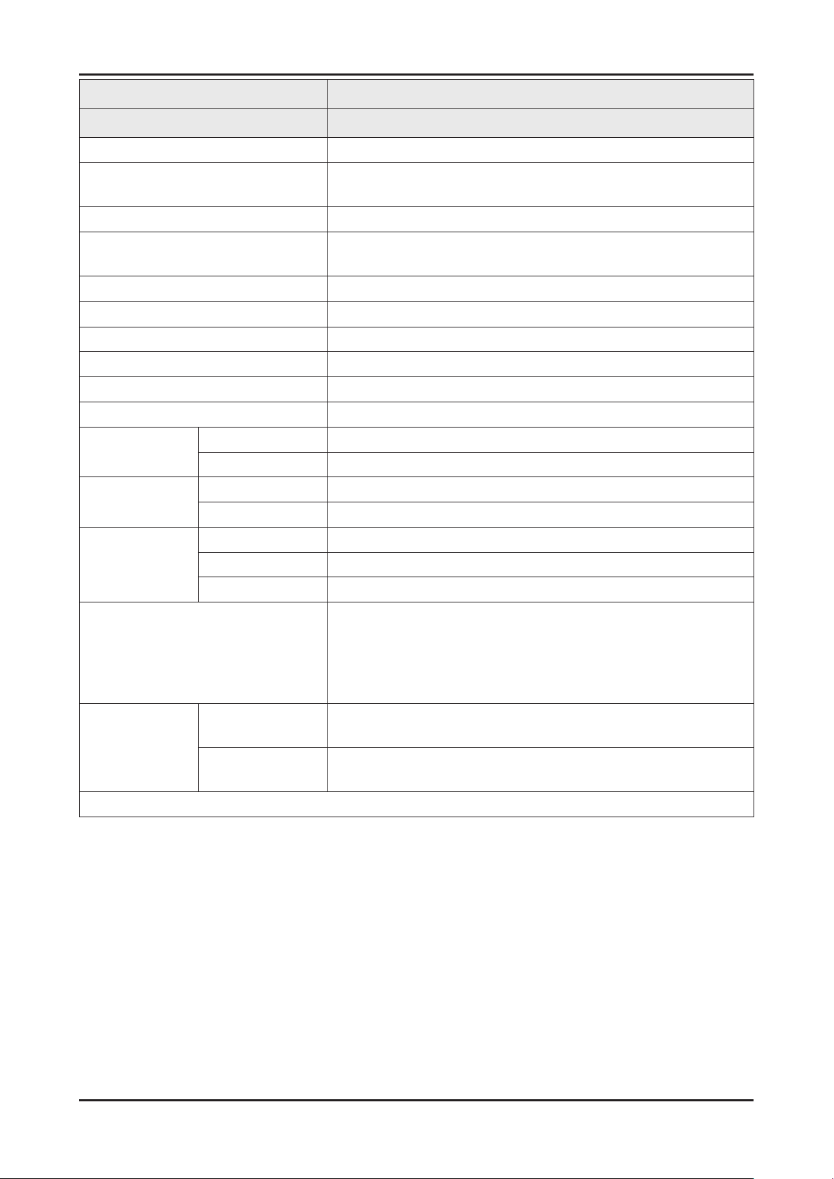
2-4. Detail Factory Option
If you replace the main board with new one, please change the factory option as well.
The options you must change are “Type”
TC300
Model Name T19C300** T22C300** T24C300**
Vendor AML CMI AUO
Panel
SMPS PD Board BN44-00504A BN44-00505A BN44-00505A
Byte Item
0 Factory Reset
1 Type 19A6TH1E 22D6TF0E 24L6TF0E
2 Local Set EU
3 Model TC300
4 SVC Model 300
4 Tuner
5 Ch Table NONE
6 Front Color NONE
CODE BN07-01043A BN07-01076A BN07-00929A
SPEC LTM185AT05-V M215HGE-L21 M240HW01-VB
AUTO/SI_ATC2/SEC_TC/SEC_ISDB/DVB_TCS2/
DVB_T2C/DVB_T2CS2/ECHO_CD/NO_TUNER
Page 21

2. Product specications
2-5. Accessories
Product Description Code. No Remark
Remote Control &
Batteries
(AAA x 2)
Quick Setup Guide BN68-04796A
Cloth clean BN63-01798B
Owners Manual BN46-00319A
AA59-00622A
4301-000121
Samsung Electronics
Service Center
Power Cord 3903-000525
D-Sub Cable BN39-00244H
Stereo Cable BN39-01286A
Stand Base -
(The part code for some
accessories may differ
depending on your
region.)
2-8
Stand Body & Screw
(1EA)
-
Page 22

4. Troubleshooting
4-1. Previous check
Check the various cable connections rst.1.
Check to see if there is a burnt or damaged cable. -
Check to see if there is a disconnected or loose cable connection. -
Check to see if the cables are connected according to the connection diagram. -
Check the power input to the Main Board.2.
4. Troubleshooting
LVDS Cable
SMPS Assy
14P Cable
Speaker
Main Assy
1 B5V 8 GND
2 SW_POWER 9 B12VS
3 B5V 10 SW_INVERTER
4 A5V 11 B13V
5 GND 12 NC
6 GND 13 B13V
7 B12VS 14 PWM_DIMM
Main Assy
Speaker
SMPS Assy
1 B13V 8 PWM_DIMM
2 B13V 9 NC
3 Vamp 10 BLU_ON
4 Vamp 11 GND
5 GND 12 GND
6 B5V 13 A5V
7 B5V 14 PS_ON
4-1
Page 23

4-2
4. Troubleshooting
4-3
4. Troubleshooting
4-2. How to check fault symptom
4-2-1. No Power
Symptom
Major
checkpoints
Diagnostics
The LED on the front panel of the monitor does not work when the power is connected and the Power
button is pressed.
Check if the Power switch on the rear panel of the monitor has been turned on.•
Check the SMPS fuse and output power of power adapter.•
Check the power part of the Main Board and check if a similar symptom appears at another output •
terminal.
Power indicator LED on?
Yes
Check the 14P power cable.
Yes
Check the ‘Stand-By 5V’, DCA5V appear
at BD207?
Yes
Check the ‘Power input of Main Ass’y’ ?
DC B13V, B5V appear at BD209(B13V),
BD213/208(B5V)?
Yes
Check the ‘Power input of submicom
IC(A3.3V)’ ?
Check the ‘Power of nand ash
IC(B3.3V)’ , ‘Power of main IC(B2.5V,
B1.1V)’, ‘Power of DDR IC(B1.5V)’
appear at IC202(#5), L201 (B3.3V),
BD1008/9/10/11 (B2.5V), BD1002
(B1.2V), BD1012 (B1.5V)?
No
No
No
No
No
Check an AC power connection.
Change 14p power cable and
SMPS.
Change SMPS.
Change the Main Assy.
Yes
Check ‘Power of LVDS (13V)’ appear
at LVDS connector Pin #1~5 of T-con
board?
Yes
Please, Contact tech support.
Caution Make sure to disconnect the power before working on the SMPS board.
No
Reconnect of Change the LVDS
cable.
Page 24

4-3
4. Troubleshooting
4-3
4. Troubleshooting
Location of Parts
Location (Main)
BD1002
BD213
BD208
BD209
BD207
IC202(#5)
L201
BD1012
BD1009
BD1010
BD1011
BD1008
Page 25

4-4
4. Troubleshooting
4-5
4. Troubleshooting
4-2-2. No video (Analog PC signal)
Symptom
Major
checkpoints
Diagnostics
Audio is normal but no picture is displayed on the screen.
Check the PC source•
Check the Arsenal, Check the Main Chipset.•
This may happen when the LVDS cable connecting the Main Board and the Panel is disconnected.•
Power indicator LED is off.
Lamp(Backlight) on, no video.
Yes
Check the PC source and check the
connection of D-SUB.
Yes
Check the Self Diagnosis (Support →
Self Diagnosis- → Picture Test).
Dose the promblem still exist self
diagnosis?
Yes
Does the signal appear at R804(R),
1
R805(G), R806(B), BD404(H),
BD405(V).
No
No
No
No
Check a set in the ‘Stand-by mode’
or ‘DPMS mode’.
Input the analog PC signal properly
Input the analog PC signal
properly.
Check CN401, PC cable.
Change the Main Assy.
Yes
Does the digital data appear at TP-
2
Caution Make sure to disconnect the power before working on the SMPS board.
EVEN_TXCLK+, EVEN_TXCLK- ,
ODD_TXCLK+, ODD_TXCLK-.
Yes
Check the LVDS cable?
Check the T-Con Board?
Replace the LCD panel?
Yes
Please, Contact tech support.
No
Check IC1001 (X9)
Change the Main Assy.
Page 26

4-5
4. Troubleshooting
4-5
4. Troubleshooting
Location of Parts
Location (Main)
A
IC1001
BD405
BD404
CN401
A
R804
EVEN_TXCLK-
R806
R805
Detail
EVEN_TXCLK+
ODD_TXCLK-
ODD_TXCLK+
Page 27

4-6
4. Troubleshooting
4-7
4. Troubleshooting
WAVEFORMS
PC input (V-sink , H-sink , R/G/B)
1
LVDS output
2
Page 28

4-2-3. No video (HDMI1 - Digital signal)
4-7
4. Troubleshooting
4-7
4. Troubleshooting
Symptom
Major
checkpoints
Diagnostics
Audio is normal but no picture is displayed on the screen.
Check the HDMI source.•
Check the HDMI switch, Check the Chelsea.•
This may happen when the LVDS cable connecting the Main Board and the Panel is disconnected.•
Power indicator LED is off.
Lamp(Backlight) on, no video.
Yes
Check the Self Diagnosis (Support →
Self Diagnosis- → Picture Test).
Dose the promblem still exist self
diagnosis?
Yes
Check the HDMI source and check the
connection of HDMI cable.
Yes
Does the signal appear at CN601_H1
(Pin#12 , #7 )(HDMI1) (HDMI RX_Clk ,
1
RX_Data).
No
No
No
No
Check a set in the ‘Stand-by mode’
Check external devices and
connections.
Input the HDMI signal properly.
Check CN601_H1.
Check HDMI cable.
Change the Main Assy.
Yes
Does the digital data appear at TP-E_
2
Caution Make sure to disconnect the power before working on the SMPS board.
TXCLK+, E_TXCLK- , O_TXCLK+,
O_TXCLK-.
Yes
Check the LVDS cable?
Check the T-Con Board?
Replace the LCD panel?
Yes
Please, Contact tech support.
No
Check IC1001 (X9).
Change the Main Assy
Page 29

4-8
4. Troubleshooting
4-9
4. Troubleshooting
Location of Parts
Location (Main)
A
IC1001
Pin #12Pin #7
A
CN601_H1
EVEN_TXCLK-
Detail
EVEN_TXCLK+
ODD_TXCLK-
ODD_TXCLK+
Page 30

WAVEFORMS
4-9
4. Troubleshooting
4-9
4. Troubleshooting
HDMI input (RX_Data, RX_Clk)
1
LVDS output
2
Page 31

4-10
4. Troubleshooting
4-11
4. Troubleshooting
4-2-4. No video (Tuner_CVBS)
Symptom
Major
checkpoints
Diagnostics
Audio is normal but no picture is displayed on the screen.
Check the Tuner CVBS source.•
Check the Tuner, Check the Chelsea.•
This may happen when the LVDS cable connecting the Main Board and the Panel is disconnected.•
Power indicator LED is off.
Lamp(Backlight) on, no video.
Yes
Check the RF source and
check the connection of RF cable.
Yes
Check the Self Diagnosis (Support →
Self Diagnosis- → Picture Test).
Dose the promblem still exist self
diagnosis?
Yes
Does the DC B1.8V. B3.3V appear at #3,
#5 Pin of Tuner.
Yes
No
No
No
No
Check a set in the ‘Stand-by mode’
Input the RF source properly.
Check external devices and
connections.
Change the Main Assy.
Check the CVBS data at #10 Pin of
Tuner.
Yes
Does the digital data appear at TP-E_
1
Caution Make sure to disconnect the power before working on the SMPS board.
TXCLK+, E_TXCLK- , O_TXCLK+,
O_TXCLK-.
Yes
Check the LVDS cable?
Check the T-Con Board?
Replace the LCD panel?
Yes
Please, Contact tech support.
No
No
Change the Main Assy.
Check IC1001 (X9).
Change the Main Assy
Page 32

4-11
4. Troubleshooting
4-11
4. Troubleshooting
Location of Parts
Location (Main) - Top
A
IC1001
A
EVEN_TXCLK-
Detail
EVEN_TXCLK+
ODD_TXCLK-
ODD_TXCLK+
Page 33

4-12
4. Troubleshooting
4-13
4. Troubleshooting
Location (Main) - Bottom
B
B
Detail
#10
#5
#3
Page 34

WAVEFORMS
4-13
4. Troubleshooting
4-13
4. Troubleshooting
1
LVDS output
Page 35

4-14
4. Troubleshooting
4-15
4. Troubleshooting
4-2-5. No video (Tuner DTV)
Symptom
Major
checkpoints
Diagnostics
Audio is normal but no picture is displayed on the screen.
Check the Tuner DTV source•
This may happen when the LVDS cable connecting the Main Board and the Panel is disconnected.•
Power indicator LED is off.
Lamp(Backlight) on, no video.
Yes
Check the RF source and
check the connection of RF cable.
Yes
Check the Self Diagnosis (Support →
Self Diagnosis- → Picture Test).
Dose the promblem still exist self
diagnosis?
Yes
Does the DC B1.8V, B3.3V appear at #3,
#5 Pin of Tuner.
Yes
No
No
No
No
Check a set in the ‘Stand-by mode’
Input the video source properly.
Check external devices and
connections.
Change the Main Assy.
Check the CVBS data at #10 Pin of
Tuner.
Yes
Does the digital data appear at TP-E_
1
Caution Make sure to disconnect the power before working on the SMPS board.
TXCLK+, E_TXCLK- , O_TXCLK+,
O_TXCLK-.
Yes
Check the LVDS cable?
Check the T-Con Board?
Replace the LCD panel?
Yes
Please, Contact tech support.
No
No
Change the Main Assy.
Check IC1001 (X9).
Change the Main Assy
Page 36

4-15
4. Troubleshooting
4-15
4. Troubleshooting
Location of Parts
Location (Main) - Top
A
IC1001
A
EVEN_TXCLK-
Detail
EVEN_TXCLK+
ODD_TXCLK-
ODD_TXCLK+
Page 37

4-16
4. Troubleshooting
4-17
4. Troubleshooting
Location (Main) - Bottom
B
B
Detail
#10
#5
#3
Page 38

WAVEFORMS
4-17
4. Troubleshooting
4-17
4. Troubleshooting
1
LVDS output
Page 39

4-18
4. Troubleshooting
4-19
4. Troubleshooting
4-2-6. No video (Video CVBS)
Symptom
Major
checkpoints
Diagnostics
Audio is normal but no picture is displayed on the screen.
Check the Video CVBS source•
This may happen when the LVDS cable connecting the Main Board and the Panel is disconnected.•
Power indicator LED is off.
Lamp(Backlight) on, no video.
Yes
Check the video source and check the
connection of video cable?
Yes
Check the Self Diagnosis (Support →
Self Diagnosis- → Picture Test).
Dose the promblem still exist self
diagnosis?
Yes
1
Does the CVBS data appear at
R816(COMP_Y_CVBS).
Yes
No
No
No
No
Check a set in the ‘Stand-by mode’
Input the video source properly.
Check external devices and
connections.
Check CN502.
Change the Main Assy.
Does the digital data appear at TP-E_
2
Caution Make sure to disconnect the power before working on the SMPS board.
TXCLK+, E_TXCLK- , O_TXCLK+,
O_TXCLK-.
Yes
Check the LVDS cable?
Check the T-Con Board?
Replace the LCD panel?
Yes
Please, Contact tech support.
No
Check IC1001 (X9).
Change the Main Assy
Page 40

4-19
4. Troubleshooting
4-19
4. Troubleshooting
Location of Parts
Location (Main) - Top
A
IC1001
R816
CN502
A
EVEN_TXCLK-
Detail
EVEN_TXCLK+
ODD_TXCLK-
ODD_TXCLK+
Page 41

4-20
4. Troubleshooting
4-21
4. Troubleshooting
Location (Main) - Bottom
B
B
Detail
#10
#5
#3
Page 42

WAVEFORMS
4-21
4. Troubleshooting
4-21
4. Troubleshooting
CVBS OUT (Grey Bar)
1
LVDS output
2
Page 43

4-22
4. Troubleshooting
4-23
4. Troubleshooting
4-2-7. No video (Component)
Symptom
Major
checkpoints
Diagnostics
Audio is normal but no picture is displayed on the screen.
Check the Component source•
This may happen when the LVDS cable connecting the Main Board and the Panel is disconnected.•
Power indicator LED is off.
Lamp(Backlight) on, no video.
Yes
Check the component source and check
the connection of component cables(Y,
Pb, Pr)?
Yes
Check the Self Diagnosis (Support →
Self Diagnosis → Picture Test).
Dose the promblem still exist self
diagnosis?
Yes
Does the CVBS data appear at
R816(COMP_Y_CVBS), R815(COMP_
1
PB), R817(COMP_PR)?
No
No
No
No
Check a set in the ‘Stand-by mode’
Input the component source
properly.
Check external devices and
connections.
Check CN502.
Change the Main Assy.
Yes
Does the digital data appear at TP-E_
2
Caution Make sure to disconnect the power before working on the SMPS board.
TXCLK+, E_TXCLK- , O_TXCLK+,
O_TXCLK-.
Yes
Check the LVDS cable?
Check the T-Con Board?
Replace the LCD panel?
Yes
Please, Contact tech support.
No
Check IC1001 (X9).
Change the Main Assy
Page 44

4-23
4. Troubleshooting
4-23
4. Troubleshooting
Location of Parts
Location (Main) - Top
A
IC1001
R815
R816
R817
CN502
A
EVEN_TXCLK-
Detail
EVEN_TXCLK+
ODD_TXCLK-
ODD_TXCLK+
Page 45

4-24
4. Troubleshooting
4-25
4. Troubleshooting
WAVEFORMS
Compnent_Y (Gray scale) / Pb / Pr (Color bar)
1
LVDS output
2
Page 46

4-2-8. No sound
4-25
4. Troubleshooting
4-25
4. Troubleshooting
Symptom
Major
checkpoints
Diagnostics
Video is normal but there is no sound.
When the speaker connectors are disconnected or damaged.•
When the sound processing part of the Main Board is not functioning.•
Check the source and connection of
sound cable (Comp/PC/DVI to HDMI)?
Yes
Check the Self Diagnosis (Support →
Self Diagnosis → Picture Test).
Dose the promblem still exist self
diagnosis?
Yes
Does the sound data appear at
R524/R525 (AV1, COMP1), R419/R420
(PC/DVI)?
Yes
Does the DC B13V appear at BD209?
Yes
No
No
No
No
Input the sound source properly.
Check external devices and
connections.
Check CN502, CN402.
Change the Main Assy.
Change the Main Assy.
Does the sound waveform appear at L-,
1
Please, Contact tech support.
Caution Make sure to disconnect the power before working on the SMPS board.
L+, R-, R+.
Yes
Replace speaker.
Yes
No
Check IC301 (Sound AMP).
Check IC1001 (X9)
Change the Main Assy.
Page 47

4-26
4. Troubleshooting
4-27
4. Troubleshooting
Location of Parts
Location (Main) - Top
A
IC1001
BD209
IC301
R524 R525
R420 R419
A
CN402
CN502
EVEN_TXCLK-
Detail
EVEN_TXCLK+
ODD_TXCLK-
ODD_TXCLK+
Page 48

WAVEFORMS
4-27
4. Troubleshooting
4-27
4. Troubleshooting
1
Speaker out
Page 49

4-28
4. Troubleshooting
4-29
4. Troubleshooting
4-4. Adjustment
4-4-1. Service Instruction
Usually, a color TV-VCR needs only slight touch-up adjustment upon installation. Check the basic characteristics such 1.
as height, horizontal and vertical sync.
Use the specied test equipment or its equivalent.2.
Correct impedance matching is essential.3.
Avoid overload. Excessive signal from a sweep generator might overload the front-end of the TV. When inserting signal 4.
markers, do not allow the marker generator to distort test result.
Connect the TV only to an AC power source with voltage and frequency as specied on the backcover nameplate.5.
Do not attempt to connect or disconnect any wire while the TV is turned on. Make sure that the power cord is 6.
disconnected before replacing any parts.
To protect aganist shock hazard, use an isolation transform.7.
4-4-2. How to Access Service Mode
Entering the Service Mode
To enter “Service Mode” Press the remote -control buttons in this sequence :
Button Functions
Channel▲/▼ Button : Select an option.•
Volume +/-,◄/► Button : Increase or decrease the value for an option.•
Menu button: Save the current settings to EEPROM and return to the previous mode.•
Number (0 ~ 9) buttons: Change the channel.•
TV/AV button: Switch to AV mode.•
Info Factory
Page 50

4-4-3. Service Mode Menu
4-29
4. Troubleshooting
4-29
4. Troubleshooting
Initial display in service mode
Option
Control
SVC
Expert
ADC/WB
Advanced
T-MX9MDEUC-XXXX
T-MX9MDEUS-XXXX
EDID SUCCESS
HDCP SUCCESS
CALIB : AV / COMP / PC / HDMI /
Option : 22D6TF0E,EU,300,NONE
FactoryCS: xxx
T-MSXDEUCIP-1000
Onboot: =xxx
SDAL-XXX
RFS : Mstar-X9 XXXX
20XX-XX-XX
F-CT1M16S-xxxx
TYPE : 22D6TF0E
Model: LT22C300
CIP FAIL
Factory Data Ver : XXX
EERC Version : XXX
DTP-AP-COMP-893
DTP-BP-HAL-0343
DTP-BP-0836
POP-PNG-12-0004
Date of purchase : XX/XX/XX
Button functions in service mode
Menu: Full Menu Display/Move to Parent Menu.•
Direction Buttons ▲/▼: Item selection by Moving the Cursor.•
Direction Buttons ◄/►: Data Increase / Decrease for Selected Item.•
Source: Cycles through the active input source that are connected to the unit.•
Page 51

4-30
4. Troubleshooting
4-31
4. Troubleshooting
Sub-Page of Service
Option
Factory Menu Name Data Remark
Type 22D6TF0E
Local Set EU
Basic Model TC300
SVC Model 300
Tuner SI_ATV2
Ch Table NONE
Front Color NONE
Control
Factory Menu Name Data Remark
EDID
EDID ON/OFF ON
EDID WRITE ALL Success
EDID WRITE PC Success
EDID WRITE HDMI …
EDID WRITE HDMI1 Success
EDID WRITE HDMI2 …
EDID WRITE HDMI3 …
EDID WRITE HDMI4 …
EDID VER HDMI 1.3
EDID PORT NONE
EDID WRITE DVI …
Sub Option
RF Mute Time 600ms
RS-232 Jack UART
Watchdog ON
WD Count 0
Lvds Format VESA
Language_Arbic EU
TOOLS Support 57
LNA Support 0
NETWORK Support Not support
IPERF Stopped
Info Link Server Type development
Info Link Country None
TTX List Flof
TTX Group UserOSD
Page 52

4-31
4. Troubleshooting
4-31
4. Troubleshooting
Control
Factory Menu Name Data Remark
24Px4 Support OFF
Power Indicator Support ON
BD Wise Support OFF
Data Service Support OFF
IIC Bus Stop OFF
Visual Test Disable
Emergency Log Copy
Checksum 0x0000
View Log
Select Log Type MICOM
Log View
Delete Log
Gemstar On/Off OFF
WSS Support ON
PVR Support OFF
CI Support ON
Eeprom Reset
EER Reset
NVR All Clear OFF
Spread Spectrum
LVDS Spread ON
Period 40K
Amplitude 1.1
DDR Spread 1.0% Spread
Echo-FS LVDS SSC ON/OFF 1
Echo-FS LVDS SSC MFR 1
Echo-FS LVDS SSC MRR 10
Echo-FS DDR SSC ON/OFF 1
Echo-FS DDR SSC MFR 1
Echo-FS DDR SSC MRR 15
NT72312 LVDS SSC ON/OFF ON
NT72312 LVDS SSC Period 30k
NT72312 LVDS SSC Modulat 1.0%
NT72312 DDR SSC ON/OFF ON
NT72312 DDR SSC Period 30K
NT72312 DDR SSC Modulat 1.0%
DDR Margin
A CTRL_OFFSET_0_3 0X0
Page 53

4-32
4. Troubleshooting
4-33
4. Troubleshooting
Control
Factory Menu Name Data Remark
A CTRL_OFFSET_D 0X0
B CTRL_OFFSET_0_3 0X0
B CTRL_OFFSET_D 0X0
H.264 Margin 8
MPEG Margin 1000
2nd mips ON
2nd mips count 0
Region PANEURO
PnP Language ENG
PC Auto Ident Auto
OTP Lock Failure
Auto Power MEMORY
KEY SENSITIVITY 128
OTA Support General
FKP Down
WIFI REGION E
e-Pop Default ON
OPTION_OTN
OPTION_MEDIAPLAY
3D OPTIMIZE VALUE 1
ECO IC TYPE NLS1006
Energy Star Logo OFF
Fast USB Booting ON
Num of Network Stream 0
PDP Option
Hotel Option
Hospitality Mode OFF
Power On …
Menu OSD …
Operation …
Music Mode …
External Source …
Eco Solution …
Cloning …
Shop Option
Shop Mode OFF
Exhibition Mode OFF
3D Cube OFF
Page 54

4-33
4. Troubleshooting
4-33
4. Troubleshooting
Control
Factory Menu Name Data Remark
Asia Option
TTX OFF
China HD OFF
NT Conversion OFF
Sepco 120Hz OFF
Unbalance OFF
FMTransmitter Support OFF
FMTransmitter Carrier OFF
AF Level adjust 3
TX Power Level 0
Mono Last Memory OFF
H Shaking OFF
Sound
High Devi OFF
Carrier_Mute OFF
Volume Curve Type1
Speaker Delay Normal 10
Pilot Level High Thld 0xFFFFEBE0h
Pilot Level Low Thld 0xFFFFEE18h
FM Prescale 68
AM Prescale 49
NICAM Prescale 45
Amp Volume 0xc7h
Amp Scale 0x67h
Amp Check Sum 0x1F6A2A08
Woofer Type 1
Woofer Scale 0x8ah
Woofer Check Sum
Speaker EQ ON
PEQ Test 0
Amp Model NTP74412
Speaker cut-off Freq 4
SPDIF PCM Gain -9dB
FM M Prescale 48
BTSC Mono Prescale 25
BTSC streo Prescale 47
SAP Prescale 43
A2 Ident High Thld 31
Page 55

4-34
4. Troubleshooting
4-35
4. Troubleshooting
Control
Factory Menu Name Data Remark
A2 Ident Low Thld 2
Carrier2 Amp High Thld 4
Carrier2 Amp Low Thld 3
Carrier2 SNR High THR 16
Carrier2 SNR Low THR 80
Audio-IP Test Ready
TruBass-CheckSum 0xFFFFFFFF
PWM Mode BD
Mic Scale 0
SubWoofer Support 0
India Sound OFF
Cong Option
Num of ATV 1
Num of DTV 1
Num of AV 1
Num of SVIDEO 0
Num of COMP 1
Num of HDMI 1
Num of PC 1
Num of SCART 1
Num of DVI 0
Num of OPTICAL Link 0
Num of MEDIA 1
Num of PANEL Button 6
Num of USB Port 1
Num of HeadPhone 0
Num of RVU 0
MFT Offset 62.5
Select LCD/PDP LCD
HDMI/DVI SEL 1
Indicator Led OFF
Wall Mount OFF
HV Flip ON
Num of Display 2
DVI/HDMI SOUND Auto
HDMI HOT PLUG Disable
HOTPLUG SWITCHING Boot
HOT PLUG DURATION 1200ms
Page 56

4-35
4. Troubleshooting
4-35
4. Troubleshooting
Control
Factory Menu Name Data Remark
CLK TERM DURATION 1200ms
HDMI FLT CNT SIG 100ms
HDMI FLT CNT LOS 100ms
UNSTABLE BAN CNT 3500ms
HDMI Err Cnt 1
HDMI ROBIN ON
HDMI Callback OFF
HDMI CTS Thld 8
HDMI CTS Cnt1 1
HDMI EQ AUTO
HDMI Write Type Separate
HDMI Switch NONE
DVI SET TIME 300ms
Type Of PANEL Button Horizontal
EcoSensor Support OFF
LEDMotionPlus Support OFF
Natural Mode Support OFF
All Share Support OFF
Relax Mode Support OFF
BT Support OFF
3D Support OFF
H Wright
HDMI Sync DE
HeadPhone Port
FANET OFF
Support MultiMedia Button ON
Cong_AV_PATH
V_HDMI IDENT TYPE 1234
V_HDMI PATH TYPE DBAC
V_EDID TYPE 21_5_HD
V_ATV CVBS_PORT_0
V_AV1 AV_COMP_G2
V_AV2 None
V_COMP1 ADC_PORT_2
V_COMP2 None
V_PC ADC_PORT_0
V_SCART1_CVBS CVBS_PORT_3
V_SCART1_RGB ADC_PORT_1
Page 57

4-36
4. Troubleshooting
4-37
4. Troubleshooting
Control
Factory Menu Name Data Remark
V_SCART2_CVBS None
V_SCART2_RGB None
A_ATV SIF
A_DTV DECODER
A_AV1 AUIN2
A_AV2 None
A_COMP1 AUIN2
A_COMP2 None
A_PC AUIN0
A_SCART1 AUIN3
A_SCART2 None
A_DVI AUIN0
A_HDMI SPDIF
A_Media DECODER
Num of IPTV 0
PVR RECORD NUM 0
Num of RUI 0
5 WAY Fuction Button R BOTTOM
Contents Bar OFF
Num Of Tuner 1
SVC
Factory Menu Name Data Remark
Test Pattern
Pattern Sel off
Logic Pattern Sel …
Logic Level Sel …
Echo-FS Pre Test Pattern 0
Echo-FS Post Test Pattern 0
Echo-FS FRC FDISPLAY ON/OFF OFF
Echo-FS 3D FDISPLAY ON/OFF OFF
Echo-FS PC Mode ON/OFF OFF
NT72312 Pre Test Pattern 0
NT72313 Post Test Pattern 0
NT72312 PC mode ON/OFF OFF
Panel Display Time 4Hr
Logic Usb D/L
Tuner Status
Page 58

4-37
4. Troubleshooting
4-37
4. Troubleshooting
SVC
Factory Menu Name Data Remark
DVB
SNR
BER
Singal Strength
Bandwidth
Frequency
LNA Status
FFT
Modulation
Code Rate
GI
Hier Modulation
Frequency Offset
Timing Offset
AGC
UCB
PLL Type
DEMOD Type
TPS LOCK
RS Lock
SSI
SQI
Firmware Version
ISDB-T
FFT Size_1
Guard Interval_1
Freq. Offset_1
SNR_1
IF AGC_1
TMCC Lock_1
TS Packet_1
Master Lock_1
A_Modulation_1
A_Code Rate_1
A_Timer InterLeave_1
A_Segments Num_1
A_Ber_1
B_Modulation_!
Page 59

4-38
4. Troubleshooting
4-39
4. Troubleshooting
SVC
Factory Menu Name Data Remark
B_Code Rate_1
B_Timer InterLeave_1
B_Segments Num_1
B_BER_1
C_Modulation_1
C_Code Rate_1
C_Timer InterLeave_1
C_Segments Num_1
C_BER_1
T-CON Usb Download ...
T-CON Check Sun Failire
Tuner Margin 10
CAM Wait Time
TS Clock delay 0
SUBMICOM UPGRADE off
BT ADDRESS 0000
BT UPGRADE ...
BT FREEPAIRING ON
SVC Reset
TOCN_TEMP READ 0.00
TEMP LAST 60.00
DCC VERSION 0x0
DCC CHK SEL 0
DCC CHECK LOCAL 0x0
DCC CHECK TOTAL
Function Upgrade off
Smart Hub Reset off
WIFI ER COUNT 0
BT ER COUNT 0
Debug Log Down 0
MulitACC Checksum Error
SVC Info
TS Clock delay TC 0
TS Clock delay S 0
Delete S/N Failure
Page 60

4-39
4. Troubleshooting
4-39
4. Troubleshooting
ADC/WB
Factory Menu Name Data Remark
ADC
AV Calibration
Comp Calibration
PC Calibration
HDMI Calibration
ADC Target
1st_AV_Low 64
1st_AV_High 880
1st_AV_Delta 2
1st_COMP_Y_Low 64
1st_COMP_Cb_Low 512
1st_COMP_Cr_Low 512
1st_COMP_Y_High 940
1st_COMP_Cb_High 512
1st_COMP_Cr_High 512
1st_COMP_Delta 2
1st_PC_Low 4
1st_PC_High 1004
1st_PC_Delta 2
2nd_ACH_Low 4
2nd_ACH_High 940
2nd_PC_Low 4
2nd_PC_High 940
2nd_Delta 2
ADC Result
1st_Y_GH 0
1st_Y_GL ...
1st_Cb_BH 0
1st_Cb_BL 0
1st_Cr_RH 0
1st_Cr_RL 0
2nd_R_L 134
2nd_G_L 134
2nd_B_L 134
2nd_R_H 49
2nd_G_H 49
2nd_B_H 49
White Balance
Page 61

4-40
4. Troubleshooting
4-41
4. Troubleshooting
ADC/WB
Factory Menu Name Data Remark
Sub Brightness 128
R-Offset 128
G-Offset 128
B-Offset 128
Sub Contrast 128
R-Gain 128
G-Gain 128
B-Gain 128
Movie R-Offset …
Movie B-Offset …
Movie R-Gain …
Movie B-Gain …
Control the sensitivity of function key is available in service mode
Option
Control
SVC
Expert
ADC/WB
Advanced
Key Sensitivity (Default : 128)
1~255 and Not Used•
Raising this value, the sensitivity decreases•
Not Used : Not use sensitivity, use Function default value•
Sub Option KEY SENSITIVITY
Page 62

4-4-4. White Balance - Calibration
4-41
4. Troubleshooting
4-41
4. Troubleshooting
Entering the Service Mode
Option
Control
SVC
Expert
ADC/WB
Advanced
ADC
ADC Target
ADC Result
WB
AV Calibration
Comp Calibration
PC Calibration
HDMI Calibration
Service Adjustment
You must perform Calibration in the Lattice Pattern before adjusting the White Balance.
Color Calibration
Adjust Specication
Source: PC1.
Setting Mode: 1080x720@60Hz2.
Pattern: Pattern #24 (Chess Pattern)3.
Use Equipment: CA210 & Master MSPG925 Generator4.
NOTE
Use other equipment only after comparing the result with that of the Master equipment.
Input mode Calibration Pattern
CVBS IN (Model_#1) Perform in NTSC B&W Pattern #24 Lattice
Component IN (Model_#6) Perform in 720p B&W Pattern #24 Lattice
PC Analog IN (Model_#21)
HDMI IN Perform in 720p B&W Pattern #24 Lattice
Perform in VESA XGA (1024x768)
B&W Pattern #24
Lattice
Page 63

4-42
4. Troubleshooting
4-43
4. Troubleshooting
Method of Color Calibration (AV)
Apply the NTSC Lattice (N0. 3) pattern signal to the AV IN 1 port1.
Press the Source button to switch to “2. AV1 ” mode
Enter Service mode3.
Select the “4. ADC” menu
Select the “5. AV Calibration” menu.
In “6. AV Calibration Off” status, press the “ ►” button to perform Calibration.
When Calibration is complete, it returns to the high-level menu.7.
You can see the change of the “AV Calibration” status from Failure to Success.8.
Method of Color Calibration (Component)
Apply the 720p Lattice (N0. 6) pattern signal to the Component IN 1 port1.
Press the Source button to switch to “2. Component1” mode
Enter Service mode3.
Select the “4. ADC” menu
Select the “5. Comp Calibration” menu.
In “6. Comp Calibration Off” status, press the “► ” button to perform Calibration.
When Calibration is complete, it returns to the high-level menu.7.
You can see the change of the “8. Comp Calibration” status from Failure to Success.
Method of Color Calibration (PC)
Apply the VESA XGA Lattice (N0. 21) pattern signal to the PC IN port1.
Press the Source button to switch to “2. PC” mode
Enter Service mode3.
Select the “4. ADC” menu
Select the “5. PC Calibration” menu.
In “6. PC Calibration Off” status, press the “ ►” button to perform Calibration.
When Calibration is complete, it returns to the high-level menu.7.
You can see the change of the “8. PC Calibration” status from Failure to Success.
Method of Color Calibration (HDMI)
Apply the 720p Lattice (N0. 6) pattern signal to the HDMI1/DVI IN port1.
Press the Source button to switch to “2. HDMI1” mode
Enter Service mode3.
Select the “4. ADC” menu
Select the “5. HDMI Calibration” menu.
In “6. HDMI Calibration Off” status, press the “ ►” button to perform Calibration.
When Calibration is complete, it returns to the high-level menu.7.
You can see the change of the “8. HDMI Calibration” status from Failure to Success.
Page 64

4-43
4. Troubleshooting
4-43
4. Troubleshooting
4-4-5. White Balance - Adjustment
NOTE
All White Balance default value for TC300 is set in a factory line already. No need calibration and do White balance
again.
Entering the Service Mode
Option
Control
SVC
Expert
ADC/WB
Advanced
ADC
ADC Target
ADC Result
White Balance
Sub Brightness
R_Offset
G_Offset
B_Offset
Sub Contrast
R_Gain
G_Gain
B_Gain
Movie R Offset
Movie B Offset
Movie R Gain
Movie B Gain
Page 65

4-44
4. Troubleshooting
4-45
4. Troubleshooting
White Ratio (Balance) Adjustment
You can adjust the white ratio in factory mode (1:Calibration, 3:White-Balance).1.
Since the adjustment value and the data value vary depending on the input source, you have to adjust these in AV, 2.
Component and HDMI modes.
The optimal values for each mode are congured by default. It varies with Panel’s size and Specication. -
Equipment : CA210•
Pattern: MIK K-7256 #92 “Flat W/B Pattern” as standard•
Use other equipment only after comparing the result with that of the Master equipment.•
Set Aging time : 60min•
Calibration and Manual setting for WB adjustment.
HDMI : Calibration at #24 Chessboard Pattern → Manual adjustment #92 pattern (720p)•
COMP: Calibration at #24 Chessboard Pattern → Manual adjustment at #92 pattern (720p)•
AV: Calibration at #24 Chessboard Pattern → Manual adjustment at #92 pattern (NTSC)•
NOTE
If nishing in HDMI mode, adjustment coordinate is almost same in AV/COMP mode.•
White Balance Manual Adjustment
P-Mode
[Dynamic Cool1]
HDMI
Comp
CVBS
[Movie Warm2]
HDMI
Comp
CVBS
Adjustment Specication
H/L 281 288
L/L - -
H/L - -
L/L - -
Adjustment Coordinate
x y Y(Luminance) T(K) + MPCD
R-Gain : 132
B-Gain : 179
Sub_CT : 128
(Sub_Brt:128 Fix)
R-Offset, B-Offset : 128
(M-Sub_CT:128 Fix)
appiled Movie W2 R/B-gain
(M-Sub_Brt:128 Fix)
appiled Movie W2 R/B-gain
10,000 (+/- 0)
-
-
-
White Balance : High light (±2), Low light (±3)•
Luminance : High light (Don’t care), Low light (±0.2 Ft/L)•
Page 66

4-45
4. Troubleshooting
4-45
4. Troubleshooting
4-5. Software Upgrade
Software Upgrade can be performed by downloading the latest rmware from samsung.com to a USB memory device.
4-5-1. How to check the SW version
Use the main menu
Click the MENU button in remote controller.1.
Select "2. Support" menu.
Locate the menu cursor "3. Software Upgrade" menu.
Click the INFO button.4.
Check the Main SW and Micom version.5.
Page 67

4-46
4. Troubleshooting
4-47
4. Troubleshooting
Use the factory mode
Access the factory mode.
Option
Control
SVC
Expert
ADC/WB
Advanced
T-MX9MDEUC-XXXX
T-MX9MDEUS-XXXX
EDID SUCCESS
HDCP SUCCESS
CALIB : AV / COMP / PC / HDMI /
Option : 22D6TF0E,EU,300,NONE
FactoryCS: xxx
T-MSXDEUCIP-1000
Onboot: =xxx
SDAL-XXX
RFS : Mstar-X9 XXXX
20XX-XX-XX
F-CT1M16S-xxxx
TYPE : 22D6TF0E
Model: LT22C300
CIP FAIL
Factory Data Ver : XXX
EERC Version : XXX
DTP-AP-COMP-893
DTP-BP-HAL-0343
DTP-BP-0836
POP-PNG-12-0004
Date of purchase : XX/XX/XX
Page 68

4-47
4. Troubleshooting
4-47
4. Troubleshooting
4-5-2. How to Upgade SW and Micom
Insert a USB drive containing the rmware upgrade downloaded from samsung.com into the TV.
Please be careful to not disconnect the power or remove the USB drive while upgrades are being applied. The TV will
turn off and turn on automatically after completing the rmware upgrade. Please check the rmware version after the
upgrades are complete (the new version will have a higher number than the older version). When software is upgraded,
video and audio settings you have When software is upgraded, video and audio settings you have you write down your
settings so that you can easily reset them after the upgrade.
Main SW upgrade
Store the sw program named "T-MX9MDEUC"(FHD) in USB memory stick.1.
Connect the USB.2.
Click the MENU button in remote controler.3.
Select "4. Support" menu.
Locate the menu cursor "5. Software Upgrade" menu.
Click the ENTER button.6.
You can upgrade by USB.7.
Page 69

4-48
4. Troubleshooting
4-49
4. Troubleshooting
Click the ENTER button.8.
Click the ENTER button.9.
Wait for upgrade complete.10.
Check the SW version.11.
Page 70

4-49
4. Troubleshooting
4-49
4. Troubleshooting
Sub micom upgrade
You can upgarde sub micom in factory mode without DDC program. But it take long time about 5 minuites.
Enter the Factory Mode and select the “1. SVC” menu.
Option
Control
SVC
Expert
ADC/WB
Advanced
Select the “2. SUBMICOM UPGRADE” menu.
Test Pattern
Panel Display Time 4Hr
Logic Usb D/L ...
Tuner Status
T-CON Usb Download ...
T-CON Check Sun Failire
Tuner Margin 10
CAM Wait Time
TS Clock delay 0
SUBMICOM UPGRADE off
BT ADDRESS 0
BT UPGRADE
BT FREEPAIRING ON
SVC Reset
TCON_TEMP READ 0.00
Press the “►” button on the remocon and wait the completion of upgrade. The system will be reset after upgrade. 3.
SUBMICOM UPGRADE Wait
WARNING
Don’t turn off the monitor until the upgrade is completed.
Page 71

5. Wiring Diagram
T-CON
Function
Main Board
Speaker
SMPS
Speaker
CNM801
CNL802
PANEL
CN201
CN302
CN1601
CN1602
CN1
5-1. Wiring Diagram
5. Wiring Diagram
5-1
Page 72

5-2
5. Wiring Diagram
5-3
5. Wiring Diagram
5-2. Board Connection
1
Main board
2
10
6
8
1 CN201 (to Powr board)
1 B5V 8 GND
2 SW_POWER 9 B12VS
3 B5V 10 SW_INVERTER
4 A5V 11 B13V
5 GND 12 NC
6 GND 13 B13V
7 B12VS 14 PWM_DIMM
7
5
3
2 CN1601_FHD (to Panel) - 22", 24"
1 Panel_VCC 16 EVEN[1]-
2 Panel_VCC 17 GND
3 Panel_VCC 18 EVEN[0]+
4 NC 19 EVEN[0]-
5 NC 20 ODD[3]+
6 NC 21 ODD[3]-
7 GND 22 ODD[CLK]+
8 EVEN[3]+ 23 ODD[CLK]-
9 EVEN[3]- 24 GND
10 EVEN[CLK]+ 25 ODD[2]+
11 EVEN[CLK]- 26 ODD[2]-
12 EVNE[2]+ 27 ODD[1]+
13 EVEN[2]- 28 ODD[1]-
14 GND 29 ODD[0]+
15 EVEN[1]+ 30 ODD[0]-
4
9
Page 73

5-3
5. Wiring Diagram
5-3
5. Wiring Diagram
2 CN1602_HD (to Panel) - 19"
1 Panel_VCC 16 ODD[CLK]+
2 Panel_VCC 17 ODD[CLK]-
3 Panel_VCC 18 GND
4 Panel_VCC 19 ODD[2]+
5 Panel_VCC 20 ODD[2]-
6 GND 21 GND
7 GND 22 ODD[1]+
8 GND 23 ODD[1]-
9 TCON_WP 24 GND
10 FORMAT 25 ODD[0]+
11 NC 26 ODD[0]-
12 GND 27 GND
13 ODD[3]+ 28 SDA_TCON
14 ODD[3]- 29 SCL_TCON
15 GND 30 NC
3 CN302 (SPEAKER)
1 R+ 3 L+
2 R- 4 L-
4 CN1201(FUNCTION)
1 IR 5 MSDA
2 GND 6 FUNC_INTR
3 A3.3V 7 LED_STB
4 MSCL 8 NC
5 CN301 (Headphone)
1 GND 4 GND
2 SL_OUT 5 IDENT
3 SR_OUT 6 NC
7 CN401 (PC)
1 PC_RED 9 PC_5V
2 PC_GREEN 10 IDENT_PC
3 PC_BLUE 11 R_FANET
4 T_FANET 12 SDA_DOWN
5 GND 13 PC_HS
6 GND 14 PC_VS
7 GND 15 SCL_DOWN
8 GND
8 CN402(PC/DIV SOUND)
1 GND 4 NC
2 PC_SL_IN 5 NC
3 PC_SR_IN
9 CN1501 (USB)
1 USB_VCC 3 USB_DP
2 USB_DM 4 GND
10 CN601_H1 (HDMI)
1 HDMI_RX2+ 11 GND
2 GND 12 HDMI_RXCLK-
3 HDMI_RX2- 13 HDMI_CEC
4 HDMI_RX1+ 14 GND
5 GND 15 SCL
6 HDMI_RX1- 16 SDA
7 HDMI_RX0+ 17 GND
8 GND 18 5V
9 HDMI_RX0- 19 HPD
10 HDMI_RXCLK+
6 CN503 (COMPONENT)
1 GND 6 GND
2 Y 7 IDENT COMP
3 PB 8 SL
4 IDENT AV 9 SR
5 PR
Page 74

5. Wiring Diagram
5-3. Connector Functions
Connector Functions
CN1601_HD/CN1602_T-CON The LVDS signal transfered from Main Board to Panel .
CN301 ↔ SMPS Supply main power and dimming signal from IP board to Main Board.
SMPS ↔ PANEL Supply power from IP board to Driver Board.
5-4. Cables
Use LVDS (Main - TCON) LEAD (Main-IP 14P) LEAD (IP-PANEL 6P/4P)
Code
Photo
18.5": BN96-020521M
21.5": BN96-21835L
24": BN96-21835J
18.5": BN39-01449V
21.5": BN39-01449L
24": BN39-01449W
18.5": BN39-01465D
21.5": BN39-01476L
24": NO USE
5-4
 Loading...