

Page 1

Owner’s
Instructions
TFT-LCD TELEVISION
...........................................................................................................................
.............
LTM1525
Page 2
Warning! Important
Safety Instructions
CAUTION: TO REDUCE THE RISK OF ELECTRIC SHOCK, DO NOT
REMOVE COVER (OR BACK). NO USER SERVICEABLE PARTS INSIDE.
REFER SERVICING TO QUALIFIED SERVICE PERSONNEL.
This symbol indicates high voltage is present inside. It is
dangerous to make any kind of contact with any inside part of
this product.
This symbol alerts you that important literature concerning
operation and maintenance has been included with this product.
Caution: To prevent electric shock, match the wide blade of plug to the wide slot,
and fully insert the plug.
To prevent damage which may result in fire or electric shock
hazard, do not expose this appliance to rain or moisture.
CAUTION
RISK OF ELECTRIC SHOCK
DO NOT OPEN
Page 3

ENG 1
Thank You for Choosing Samsung
Thank you for choosing Samsung! Your new Samsung TV represents the latest in television technology.
We designed it with easy-to-use on-screen menus and closed captioning capabilities, making it one of the
best products in its class. We are proud to offer you a product that will provide convenient, dependable
service and enjoyment for years to come.
Important Safety Information
Always be careful when using your TV receiver. To reduce the risk of fire, electrical shock, and other
injuries, keep these safety precautions in mind when installing, using, and
maintaining your machine.
• Read all safety and operating instructions before operating your TV.
• Keep the safety and operating instructions for future reference.
• Heed all warnings on the TV receiver and in the operating instructions.
• Follow all operating and use instructions.
• Unplug the TV receiver from the wall outlet before cleaning. Use a damp cloth; do not use liquid or
aerosol cleaners.
• Never add any attachments and/or equipment without approval of the manufacturer. Such additions
can increase the risk of fire, electric shock, or other personal injury.
• Do not use the TV receiver where contact with or immersion in water is a possibility, such as near bath
tubs, sinks, washing machines, swimming pools, etc.
• Do not place the TV on an unstable cart, stand, tripod, bracket, or table
where it can fall. A falling TV can cause serious injury to a child or adult,
and serious damage to the appliance. Use only with a cart, stand, tripod,
bracket, or table recommended by the manufacturer or sold with the TV.
Follow the manufacturer’s instructions when mounting the unit, and use a
mounting accessory recommended by the manufacturer. Move the TV and
cart with care. Quick stops, excessive force, and uneven surfaces can
make the unit and cart unsteady and likely to overturn.
•Provide ventilation for the TV receiver. The unit is designed with slots in
the cabinet for ventilation to protect it from overheating. Do not block these openings with any object,
and do not place the TV receiver on a bed, sofa, rug, or other similar surface. Do not place it near a
radiator or heat register. If you place the TV receiver on a rack or bookcase, ensure that there is adequate ventilation and that you’ve followed the manufacturer’s instructions for mounting.
• Operate your TV receiver only from the type of power source indicated on the marking label. If you are
not sure of the type of power supplied to your home, consult your appliance dealer or local power
company.
• Use only a grounded or polarized outlet. For your safety, this TV is equipped with a polarized alternating current line plug having one blade wider than the other. This plug will fit into the power outlet
only one way. If you are unable to insert the plug fully into the outlet, try reversing the plug. If the plug
still does not fit, contact your electrician to replace your outlet.
•Protect the power cord. Power supply cords should be routed so that they won’t be walked on or
pinched by objects placed on or against them. Pay particular attention to cords at plugs, convenience
receptacles, and the point where they exit from the unit.
Page 4
ENG 2
• Unplug the TV from the wall outlet and disconnect the antenna or cable system during a lightning
storm or when left unattended and unused for long periods of time. This will prevent damage to the
unit due to lightning and power-line surges.
•Avoid overhead power lines. An outside antenna system should not be placed in the vicinity of overhead power lines or other electric light or power circuits or where it can fall into such power lines or
circuits. When installing an outside antenna system, be extremely careful to keep from touching the
power lines or circuits. Contact with such lines can be fatal.
• Do not overload the wall outlet or extension cords. Overloading can result in fire or electric shock.
• Do not insert anything through the openings in the unit, where they can touch dangerous voltage
points or damage parts. Never spill liquid of any kind on the TV.
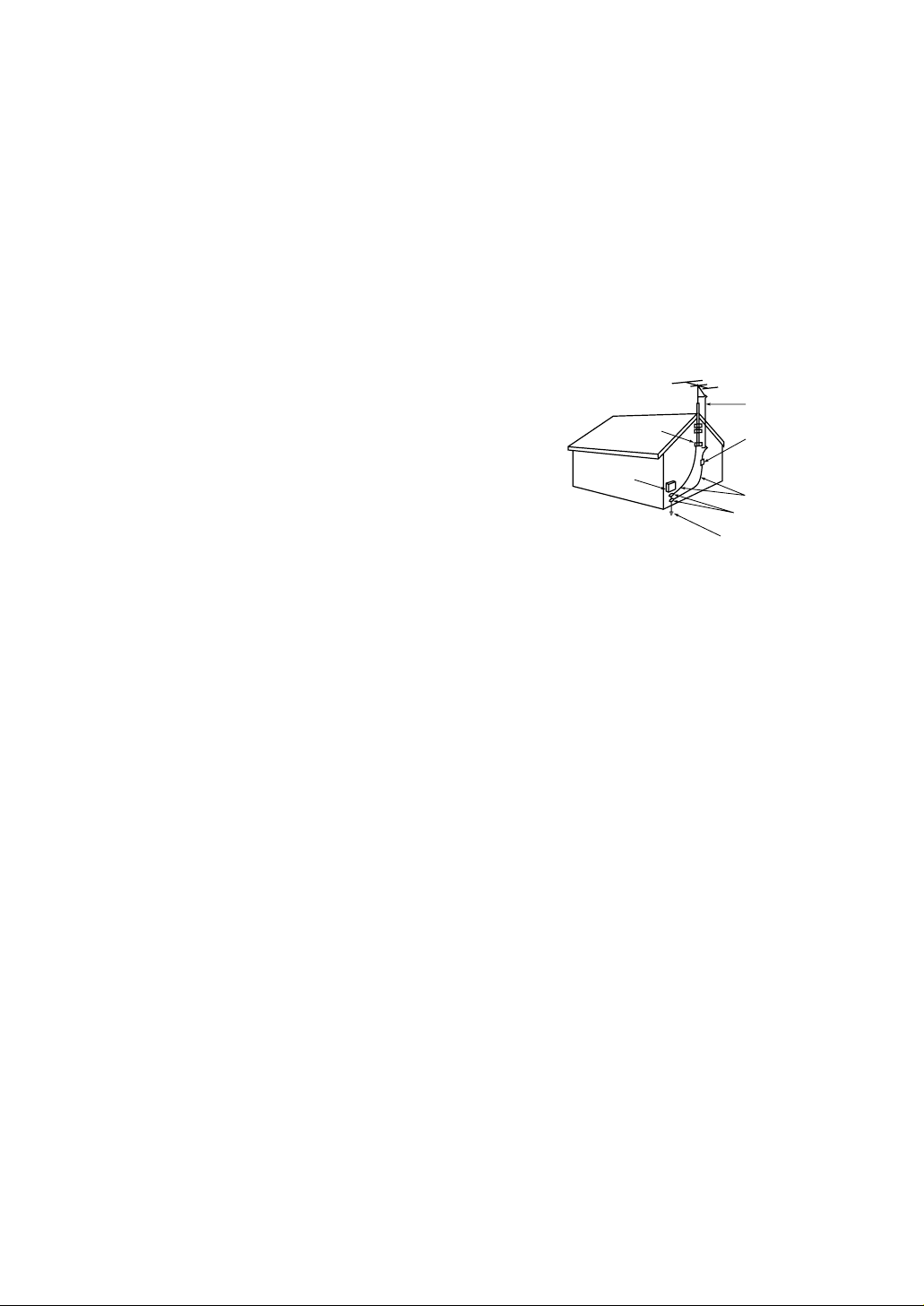
•Ground outdoor antennas. If an outside antenna or cable
system is connected to the TV, be sure the antenna or cable
system is grounded so as to provide some protection against
voltage surges and built-up static charges. Section 810 of
the National Electrical Code, ANSI/NFPA No.70-1984, provides information about proper grounding of the mast and
supporting structure, grounding of the lead-in wire to an
antenna discharge unit, size of grounding conductors, location of antenna discharge unit, connection to grounding
electrodes, and requirements for the grounding electrode.
• Do not attempt to service the TV yourself. Refer all servicing to qualified service personnel. Unplug the unit from the wall outlet and refer servicing to qualified
service personnel under the following conditions:
- when the power-supply cord or plug is damaged
- if liquid has been spilled on the unit or if objects have fallen into the unit
- if the TV has been exposed to rain or water
- if the TV does not operate normally by following the operating instructions
- if the TV has been dropped or the cabinet has been damaged
- when the TV exhibits a distinct change in performance
• If you make adjustments yourself, adjust only those controls that are covered by the operating instructions. Adjusting other controls may result in damage and will often require extensive work by a qualified technician to restore the TV to normal.
• When replacement parts are required, be sure the service technician uses replacement parts specified
by the manufacturer or those that have the same characteristics as the original part. Unauthorized substitutions may result in additional damage to the unit.
• Upon completion of any service or repairs to this TV, ask the service technician to
perform safety checks to determine that the TV is in a safe operating condition.
• Keep all power adaptors apart.
Possible fire hazard.
• Keep the power adaptor away from any other heater.
Possible fire hazard.
• Remove and discard the plastic cover from the power adaptor before use.
Possible fire hazard.
• Always keep the power adaptor in a well-ventilated area.
EXAMPLE OF
ANTENNA GROUNDING
GROUND CLAMP
ELECTRIC
SERVICE
EQUIPMENT
NEC — NATIONAL ELECTRICAL CODE
ANTENNA
LEAD IN WIRE
ANTENNA
DISCHARGE UNIT
(NEC SECTION 810-20)
GROUNDING
CONDUCTORS
(NEC SECTION 810-21)
GROUND CLAMPS
POWER SERVICE GROUNDING
ELECTRODE SYSTEM
(NEC ART 250, PART H)
Page 5

ENG 3
CONTENTS
Chapter 1: Your New TV . . . . . . . . . . . . . . .1.1
List of Features . . . . . . . . . . . . . . . . . . . . . . . . . . . . . . . . . . . . . . . . . .1.1
Accessories . . . . . . . . . . . . . . . . . . . . . . . . . . . . . . . . . . . . . . . . . . . . .1.1
Familiarizing Yourself with The TV . . . . . . . . . . . . . . . . . . . . . . . . . .1.2
Front Panel Buttons . . . . . . . . . . . . . . . . . . . . . . . . . . . . . . .1.2
Side Panel Buttons & Jack . . . . . . . . . . . . . . . . . . . . . . . . . .1.3
Rear Panel Jacks . . . . . . . . . . . . . . . . . . . . . . . . . . . . . . . . . .1.4
Remote Control . . . . . . . . . . . . . . . . . . . . . . . . . . . . . . . . . .1.5
Chapter 2: Installation . . . . . . . . . . . . . . . . 2.1
Connecting VHF and UHF Antennas . . . . . . . . . . . . . . . . . . . . . . . . .2.1
Antennas with 300-ohm Flat Twin Leads . . . . . . . . . . . . . . .2.1
Antennas with 75-ohm Round Leads . . . . . . . . . . . . . . . . . .2.2
Separate VHF and UHF Antennas . . . . . . . . . . . . . . . . . . . .2.2
Connecting Cable TV . . . . . . . . . . . . . . . . . . . . . . . . . . . . . . . . . . . . .2.2
Cable without a Cable Box . . . . . . . . . . . . . . . . . . . . . . . . . .2.2
Connecting to a Cable Box that Descrambles All Channels .2.3
Connecting to a Cable Box that Descrambles Some Channels
. .2.3
Connecting a VCR . . . . . . . . . . . . . . . . . . . . . . . . . . . . . . . . . . . . . . .2.5
Connecting an S-VHS VCR . . . . . . . . . . . . . . . . . . . . . . . . .2.6
Connecting a DVD Player . . . . . . . . . . . . . . . . . . . . . . . . . . . . . . . . .2.7
Connecting a Digital TV Set-Top Box . . . . . . . . . . . . . . . . . . . . . . . . .2.7
Connecting a Camcorder . . . . . . . . . . . . . . . . . . . . . . . . . . . . . . . . . .2.8
Installing Batteries in the Remote Control . . . . . . . . . . . . . . . . . . . . .2.9
Chapter 3: Operation . . . . . . . . . . . . . . . . . .3.1
Tu r ning the TV On and Off . . . . . . . . . . . . . . . . . . . . . . . . . . . . . . . .3.1
Plug & Play Feature . . . . . . . . . . . . . . . . . . . . . . . . . . . . . . . . . . . . . .3.1
Viewing the Menus and On-Screen Displays . . . . . . . . . . . . . . . . . . .3.3
Viewing the Menus . . . . . . . . . . . . . . . . . . . . . . . . . . . . . . .3.3
Viewing the Display . . . . . . . . . . . . . . . . . . . . . . . . . . . . . . .3.3
Selecting a Menu Language . . . . . . . . . . . . . . . . . . . . . . . . . . . . . . . .3.4
Memorizing the Channels . . . . . . . . . . . . . . . . . . . . . . . . . . . . . . . . .3.5
Selecting the Video Signal-source . . . . . . . . . . . . . . . . . . . . .3.5
Storing Channels in Memory (Automatic Method) . . . . . . . .3.6
Adding and Erasing Channels (Manual Method) . . . . . . . . .3.7
Changing Channels . . . . . . . . . . . . . . . . . . . . . . . . . . . . . . . . . . . . . .3.7
Using the Channel Buttons . . . . . . . . . . . . . . . . . . . . . . . . .3.7
Directly Accessing Channels . . . . . . . . . . . . . . . . . . . . . . . .3.7
Using the Pre-CH Button to select the Previous Channel . . .3.7
Adjusting the Volume . . . . . . . . . . . . . . . . . . . . . . . . . . . . . . . . . . . . .3.8
Using Mute . . . . . . . . . . . . . . . . . . . . . . . . . . . . . . . . . . . . .3.8
Setting the Clock . . . . . . . . . . . . . . . . . . . . . . . . . . . . . . . . . . . . . . . .3.9
Customizing the Picture . . . . . . . . . . . . . . . . . . . . . . . . . . . . . . . . . .3.10
Using Automatic Picture Settings . . . . . . . . . . . . . . . . . . . . . . . . . . .3.11
Customizing the Sound . . . . . . . . . . . . . . . . . . . . . . . . . . . . . . . . . .3.12
Using Automatic Sound Settings . . . . . . . . . . . . . . . . . . . . . . . . . . .3.13
Viewing a VCR or Camcorder Tape . . . . . . . . . . . . . . . . . . . . . . . . .3.14
Page 6

Chapter 4: Special Features . . . . . . . . . . . .4.1
Fine Tuning Channels . . . . . . . . . . . . . . . . . . . . . . . . . . . . . . . . . . . .4.1
LNA (Low Noise Amplifier) . . . . . . . . . . . . . . . . . . . . . . . . . . . . . . . .4.2
Setting the Blue Screen Mode . . . . . . . . . . . . . . . . . . . . . . . . . . . . . . .4.3
Changing the Screen Size (DVD/DTV) . . . . . . . . . . . . . . . . . . . . . . . .4.4
Freezing the Picture . . . . . . . . . . . . . . . . . . . . . . . . . . . . . . . . . . . . . .4.4
Special Sound Options . . . . . . . . . . . . . . . . . . . . . . . . . . . . . . . . . . . .4.5
Setting Multi-channel Soundtrack (MTS) . . . . . . . . . . . . . . .4.5
Choosing a Multi-Channel Soundtrack (MTS) . . . . . . . . . . .4.6
Auto Volume . . . . . . . . . . . . . . . . . . . . . . . . . . . . . . . . . . . .4.7
Virtual Dolby . . . . . . . . . . . . . . . . . . . . . . . . . . . . . . . . . . . .4.8
Selecting the Headphone Sound . . . . . . . . . . . . . . . . . . . . .4.9
Setting the On/Off Timer . . . . . . . . . . . . . . . . . . . . . . . . . . . . . . . . .4.10
Setting the Sleep Timer . . . . . . . . . . . . . . . . . . . . . . . . . . . . . . . . . .4.11
Viewing Closed Captions . . . . . . . . . . . . . . . . . . . . . . . . . . . . . . . . .4.12
Viewing Picture-in-Picture . . . . . . . . . . . . . . . . . . . . . . . . . . . . . . . .4.13
Activating Picture-in-Picture . . . . . . . . . . . . . . . . . . . . . . .4.13
Selecting a Signal Source (External A/V) for PIP . . . . . . . . .4.14
Swapping the Contents of the PIP image and Main image .4.14
Changing the PIP Channel . . . . . . . . . . . . . . . . . . . . . . . . .4.14
Changing the Location of the PIP Window . . . . . . . . . . . .4.14
Changing the Size of the PIP Window . . . . . . . . . . . . . . . .4.14
Using the V-Chip . . . . . . . . . . . . . . . . . . . . . . . . . . . . . . . . . . . . . . .4.15
Setting Up Your Personal ID Number (PIN) . . . . . . . . . . . .4.15
How to Enable/Disable the V-Chip . . . . . . . . . . . . . . . . . . .4.16
How to Set up Restrictions Using the “TV guidelines” . . . .4.16
How to Set up Restrictions using the MPAA Ratings:
G, PG, PG-13, R, NC-17, X . . . . . . . . . . . . . . . . . . . . . . . .4.18
How to Reset the TV after the V-Chip
Blocks a Channel (“Emergency Escape”) . . . . . . . . . . . . . .4.19
Chapter 5: PC Display . . . . . . . . . . . . . . . . .5.1
Using Your TV as a Computer (PC) Display . . . . . . . . . . . . . . . . . . . .5.1
How to Connect Your PC to the TV . . . . . . . . . . . . . . . . . . .5.1
How to Set up Your PC Software (Windows only) . . . . . . . .5.2
Adjusting the Screen Quality . . . . . . . . . . . . . . . . . . . . . . . .5.3
Changing the Screen Position . . . . . . . . . . . . . . . . . . . . . . .5.4
Changing the Screen Color Standard . . . . . . . . . . . . . . . . . .5.5
Adjusting the Screen Color Settings . . . . . . . . . . . . . . . . . . .5.6
Chapter 6: Troubleshooting . . . . . . . . . . . .6.1
Identifying Problems . . . . . . . . . . . . . . . . . . . . . . . . . . . . . . . . . . . . .6.1
Appendix . . . . . . . . . . . . . . . . . . . . . . . . . . .A.1
Display Modes . . . . . . . . . . . . . . . . . . . . . . . . . . . . . . . . . . . . . . . . . .A.1
Retractable Stand . . . . . . . . . . . . . . . . . . . . . . . . . . . . . . . . . . . . . . . .A.2
Using the Anti-Theft Kensington Lock . . . . . . . . . . . . . . . . . . . . . . . .A.2
Pin Assignments . . . . . . . . . . . . . . . . . . . . . . . . . . . . . . . . . . . . . . . .A.3
Cleaning and Maintaining Your TV . . . . . . . . . . . . . . . . . . . . . . . . . .A.3
Using Your TV in Another Country . . . . . . . . . . . . . . . . . . . . . . . . . .A.3
Specifications . . . . . . . . . . . . . . . . . . . . . . . . . . . . . . . . . . . . . . . . . . .A.4
ENG 4
CONTENTS
Page 7
ENG 1.1
List of Features
Your TV was designed with the latest technology. This TV is a high-performance unit that
includes the following special features:
• Easy-to-use remote control
• Easy-to-use on-screen menu system
• Automatic timer to turn the TV on and off
• Adjustable picture and sound settings that can be stored in the TV’s memory
• Automatic channel tuning for up to 181 channels
• A special filter to reduce or eliminate reception problems
• Fine tuning control for the sharpest picture possible
• A built-in multi-channel sound decoder for stereo and bilingual listening
• Built-in, dual channel speakers
• A special sleep timer
• Headphone jack for private listening
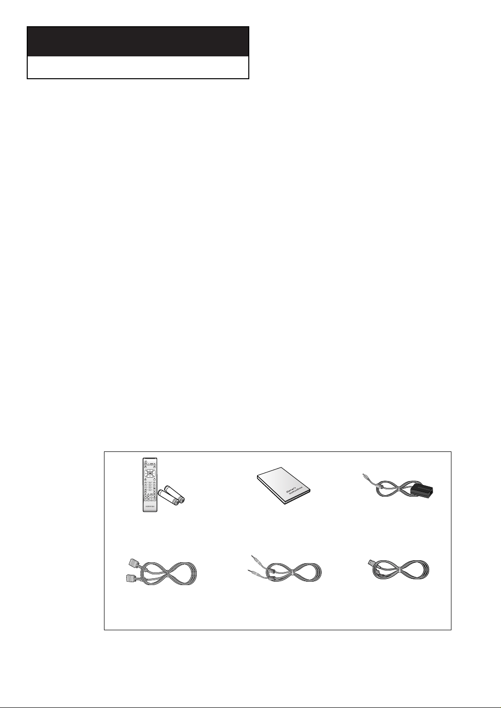
Accessories
Please make sure the following items are included with your LCD TV. If any items are
missing, contact your dealer.
Chapter 1
YOUR N EW TV
Remote Control &
Batteries (AAA x 2)
Owner’s
Instructions
DC Adapter
Power CordStereo Cable
15-pin D-Sub
Signal Cable
Page 8
ENG 1.2
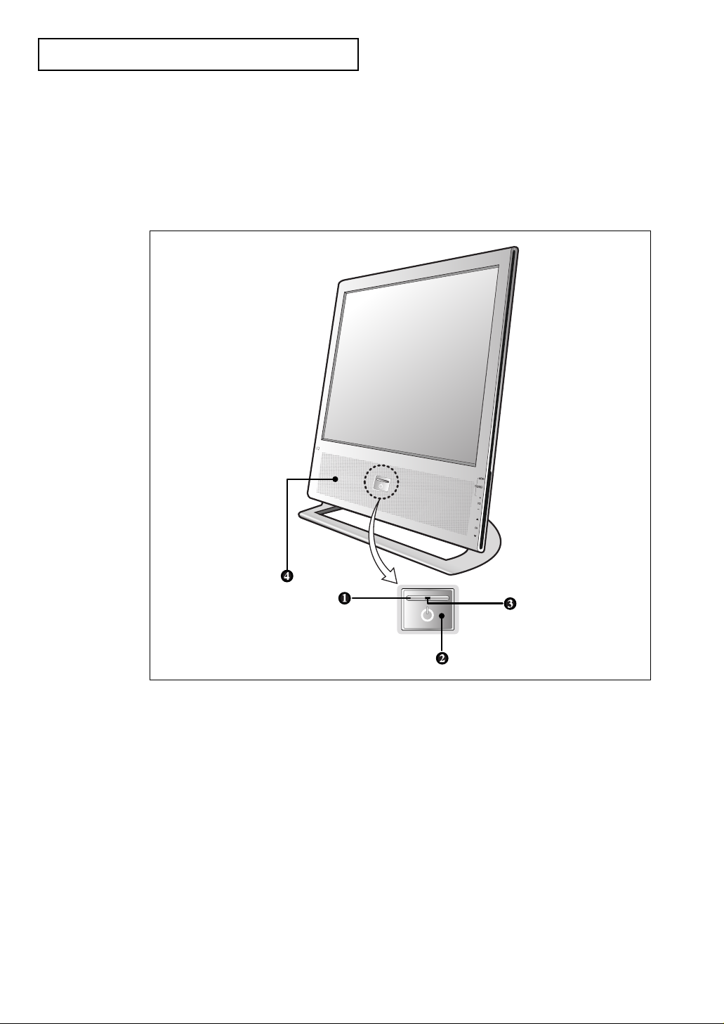
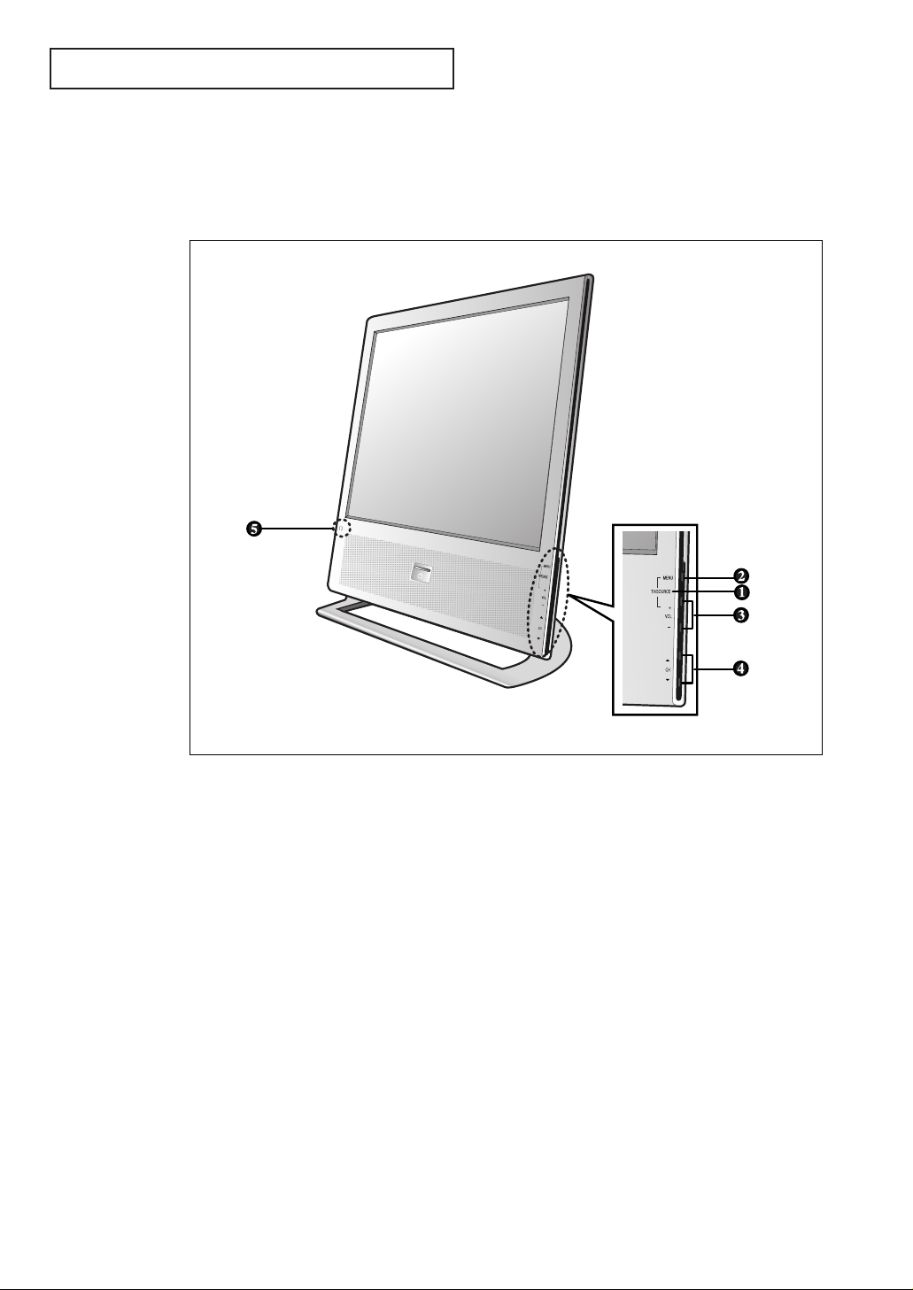
Familiarizing Yourself with The TV
Front Panel Buttons
To use the more advanced features, you must use the remote control.
YOUR N EW TV
Œ
POWER
Press to turn the TV on and off.
´
Remote Control Sensor
Aim the remote control towards this spot on the
TV.
ˇ
POWER & TIMER indicator
Lights up when you turn the power off.
¨
SPEAKER
Page 9
ENG 1.3
YOUR N EW TV
Œ
TV/SOURCE
Press the MENU and Volume up buttons simultaneously to change the signal source.
´
MENU
Press to see an on-screen menu of your TV's features.
ˇ
VOL(VOLUME) – , +
Press to increase or decrease the
volume. Also used to select items on the onscreen menu.
¨
CH ▼ and CH ▲
Press to change channels. Also press to highlight
various items on the on-screen menu.
ˆ
HEADPHONE JACK
Connect a set of external headphones to this jack
for private listening.
Side Panel Buttons & Jack
The buttons on the side panel control your TV’s basic features, including the on-screen
menu, you can use the side panel jack to connect headphones.
Page 10
ENG 1.4
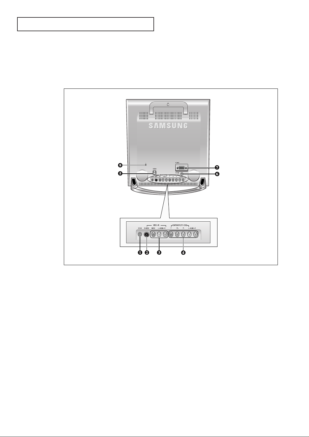
YOUR N EW TV
Rear Panel Jacks
Use the rear panel jacks to connect an A/V component such as a VCR, Camcorder,
Video Game or DVD player.
For more information on connecting equipment, see pages 2.1 – 2.9.
Œ
POWER INPUT CONNECTOR
´
SUPER VIDEO IN JACK
Used to connect an S-Video signal from a
camcorder or a video game
ˇ
VIDEO/AUDIO IN JACKS
Used to connect a video/audio signal from a camcorder or a video game.
¨
COMPONENT (DTV/DVD)
Connect component video/audio from a DVD
player or Set-Top Box.
ˆ
TV ANTENNA
Connect to an antenna or cable TV system.
Ø
PC AUDIO INPUT
Connect these to the audio-output jacks on your
PC.
∏
PC VIDEO INPUT
Connect the video output port on your PC.
”
Kensington lock
(See page A.2)
Page 11
ENG 1.5
YOUR N EW TV
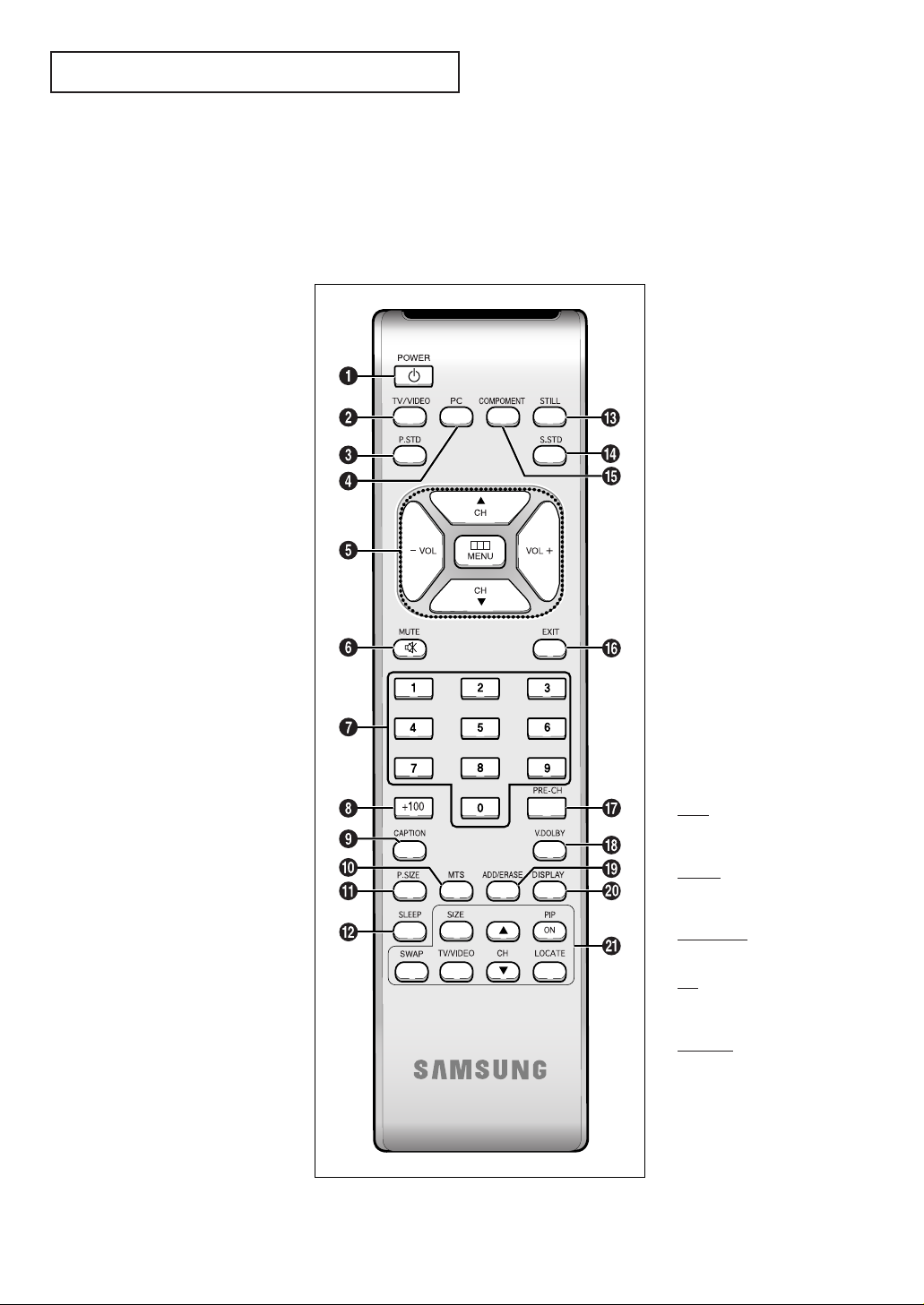
Remote Control
You can use the remote control up to about 23 feet from the TV. When using the remote,
always point it directly at the TV.
Œ
POWER
Turns the TV on and off.
´
TV/VIDEO
Press to display all of the
available video sources.
ˇ
P.STD
Adjust the TV picture by
selecting one of the preset
factory settings (or select your
personal, customized picture
settings).
¨
PC
Press to switch to the PC mode.
ˆ
MENU
Displays the main on-screen
menu.
VOL -, VOL +
Press to increase or decrease the
volume. (Also used to make selections on the on-screen menus.)
CH▲ and CH▼
(Channel Up/Down)
Press CH▲ or CH▼ to change
channels. (Also used to highlight
selections on the on-screen
menus.)
Ø
MUTE
Press to temporarily cut off
the sound.
∏
Number buttons
Press to select channels directly
on the TV.
”
+100
Press to select channels over 100.
For example, to select channel
121, press “+100,” then press “2”
and “1.”
’
CAPTION
Controls the caption decoder.
˝
MTS (Multichannel
Television Stereo)
Press to choose stereo, mono or
Separate Audio Program (SAP
broadcast).
Ô
P.SIZE
Press to change the screen size.
SLEEP
Press to select a preset time
interval for automatic shutoff.
Ò
STILL
Press to stop the action during a
particular scene. Press again to
resume normal video.
Ú
S.STD
Adjust the TV sound by selecting
one of the preset factory settings
(or select your personal,
customized sound settings).
Æ
COMPONENT
Press to switch to the COMPONENT mode.
ı
EXIT
Press the menu to exit.
˜
PRE-CH
Tunes to the previous channel.
¯
V.DOLBY
This feature allows the TV L/R
speakers to provide a home
Theater-like Dolby effect.
˘
ADD/ERASE
Press to add or erase channels in
the TV’s memory.
¿
DISPLAY
Press to display the current channel and the audio-video
settings.
¸
PIP controls
SIZE
When you press the size button,
the “Not available” screen will
appear.
SW
AP
When you press the SWAP button,
the “Not available” screen will
appear.
TV/VIDEO
Press to select one of the available
signal sources for the PIP window.
CH
Displays the available channels in
sequence. (These buttons change
channels in the PIP window only).
LOCA
TE
Press to move the PIP window to
any of the four corners of the TV
screen.
Page 12
ENG 2.1
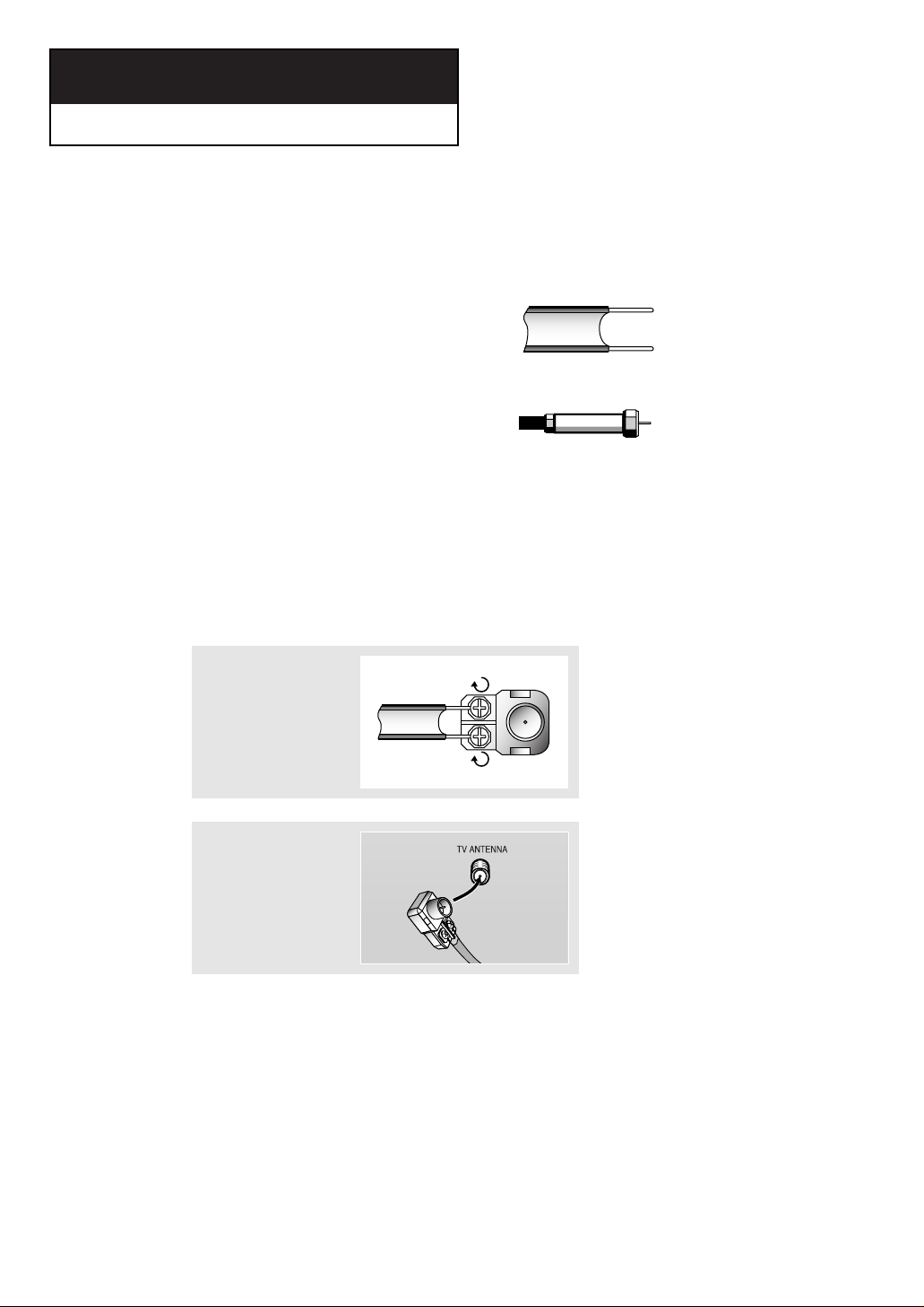
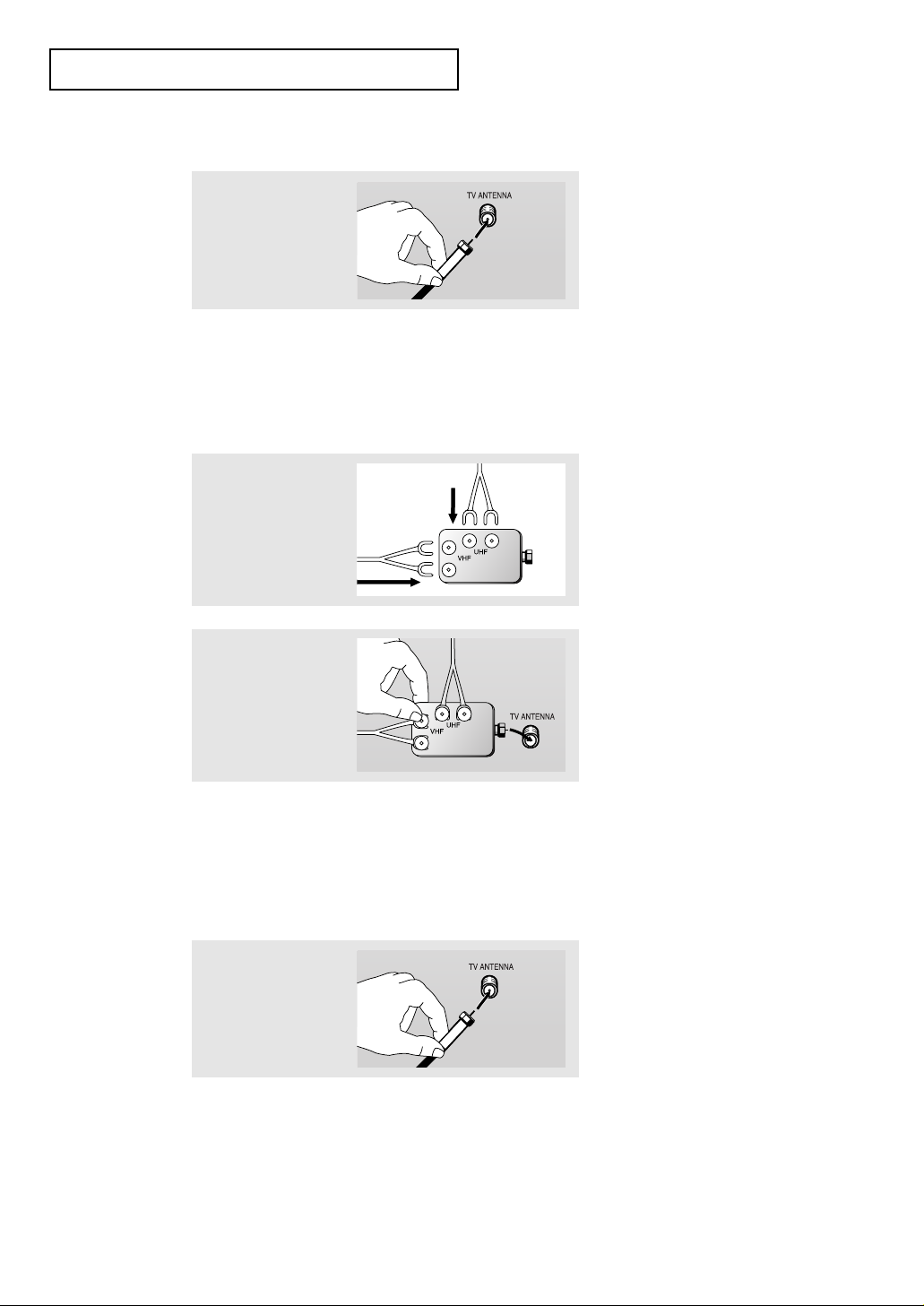
Connecting VHF and UHF Antennas
If your antenna has a set of leads that
look like this, see “Antennas with
300-ohm Flat Twin Leads,” below.
If your antenna has one lead that looks
like this, see “Antennas with 75-ohm
Round Leads,” on page 2.2.
If you have two antennas, see “Separate
VHF and UHF Antennas,” on page 2.2.
Antennas with 300-ohm Flat Twin Leads
If you are using an off-air antenna (such as a roof antenna or “rabbit ears”) that has
300-ohm twin flat leads, follow the directions below.
Chapter 2
INSTALLATION
1
Place the wires from the
twin leads under the
screws on a 300-75 ohm
adaptor (not supplied).
Use a screwdriver to
tighten the screws.
2
Plug the adaptor into the
TV ANTENNA terminal
on the bottom of the
back panel.
2
Page 13
ENG 2.2
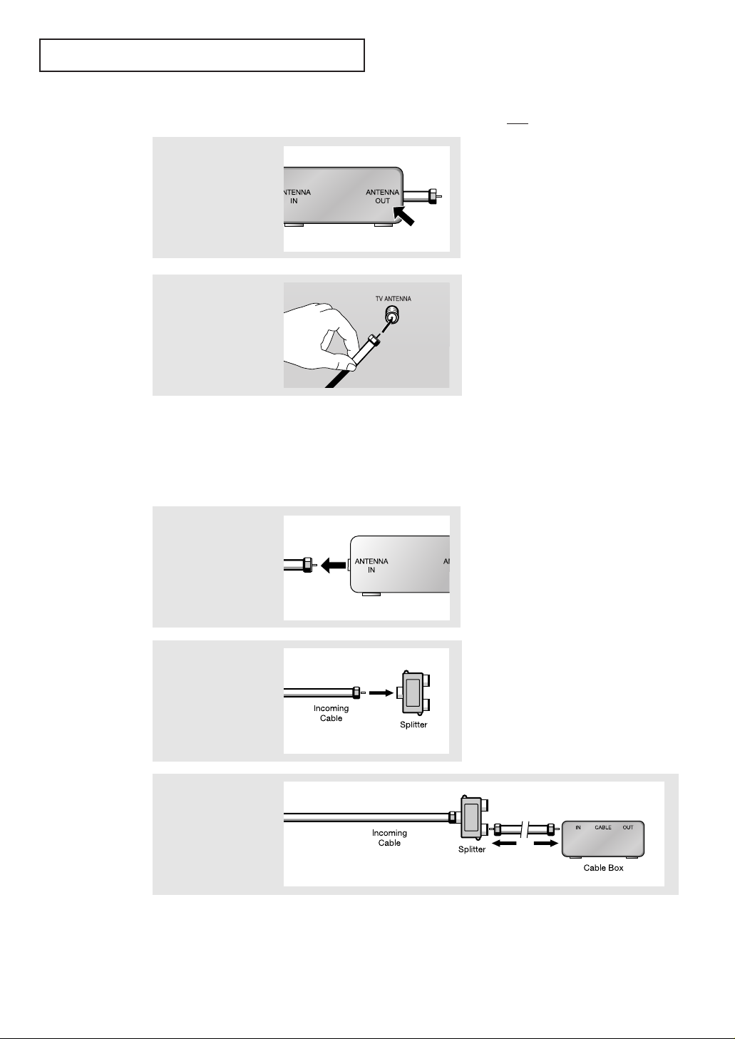
Connecting Cable TV
To connect to a cable TV system, follow the instructions below.
Cable without a Cable Box
▼
1
Plug the incoming cable
into the TV ANTENNA
antenna terminal on
back of the TV.
Because this TV is
cable-ready, you do not need a
cable box to view unscrambled cable
channels.
2
Plug the combiner
into the TV ANTENNA terminal on the
bottom of the rear
panel.
INSTALLATION
Antennas with 75-ohm Round Leads
1
Plug the antenna lead
into the TV ANTENNA
terminal on the bottom
of the back panel.
Separate VHF and UHF Antennas
If you have two separate antennas for your TV (one VHF and one UHF), you must
combine the two antenna signals before connecting the antennas to the TV. This
procedure requires a an optional combiner-adaptor (available at most electronics shops).
1
Connect both antenna
leads to the combiner.
Page 14
ENG 2.3
INSTALLATION
Connecting to a Cable Box that Descrambles All Channels
▼
1
Find the cable that is
connected to the
ANTENNA OUT terminal
on your cable box.
This terminal might be labeled
“ANT OUT,” “VHF OUT,” or simply,
“OUT.”
2
Connect the other end of
this cable to the TV
ANTENNA terminal on
the back of the TV.
Connecting to a Cable Box that Descrambles Some Channels
If your cable box descrambles only some channels (such as premium channels), follow the
instructions below. You will need a two-way splitter, an RF (A/B) switch, and four lengths of
coaxial cable. (These items are available at most electronics stores.)
▼
1
Find and disconnect the
cable that is connected
to the ANTENNA IN
terminal on your
cable box.
This terminal might be labeled
“ANT IN,” “VHF IN,” or simply,
“IN.”
2
Connect this cable to a
two-way splitter.
3
Connect a coaxial cable
between an OUTPUT terminal on the splitter and
the IN terminal on the
cable box.
Page 15

ENG 2.4
4
Connect a coaxial
cable between the
ANTENNA OUT terminal on the cable box
and the B–IN terminal
on the A/B switch.
5
Connect another cable
between the other
OUT terminal on the
splitter and the A–IN
terminal on the RF
(A/B) switch.
6
Connect the last coaxial cable between the
OUT terminal on the RF
(A/B) switch and the
VHF/UHF terminal on
the rear of the TV.
INSTALLATION
After you’ve made this connection, set the A/B switch to the “A” position for normal viewing.
Set the A/B switch to the “B” position to view scrambled channels. (When you set the A/B
switch to “B,” you will need to tune your TV to the cable box’s output channel, which is usually channel 3 or 4.)
Page 16
ENG 2.5
INSTALLATION
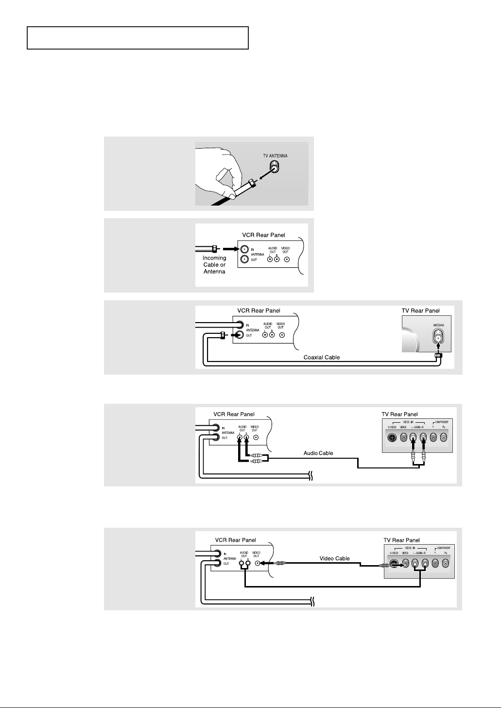
3
Connect a coaxial cable
between the ANTENNA
OUT terminal on the VCR
and the antenna terminal
on the TV.
4
Connect a set of audio
cables between the
AUDIO OUT jacks on
the VCR and the
AUDIO jacks on the TV.
5
Connect a video cable
between the VIDEO
OUT jack on the VCR
and the VIDEO jack on
the TV.
Follow the instructions in “Viewing a VCR or Camcorder Tape” to view your VCR tape.
A coaxial cable is usually included with a VCR. (If not, check your local electronics
store).
If you have a “mono” (non-stereo) VCR, use the Y-connector (not supplied) to hook up
to the left and right audio input jacks of the TV. If your VCR is stereo, you must connect
two cables.
Connecting a VCR
These instructions assume that you have already connected your TV to an antenna or a cable
TV system (according to the instructions on pages 2.1-2.3). Skip step 1 if you have not yet
connected to an antenna or a cable system.
1
Unplug the cable or
antenna from the back
of the TV.
2
Connect the cable or
antenna to the ANTENNA
IN terminal on the back of
the VCR.
Page 17
ENG 2.6
INSTALLATION
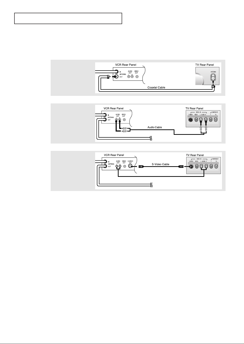
3
Connect an S-video cable
between the S-VIDEO OUT
jack on the VCR and the
S-VIDEO INPUT jack on
the TV.
An S-video cable is usually included with an S-VHS VCR. (If not, check your local
electronics store.)
1
To begin, follow steps
1–3 in the previous
section to connect the
antenna or cable to
your VCR and your TV.
Connecting an S-VHS VCR
Your Samsung TV can be connected to an S-Video signal from an S-VHS VCR.
(This connection delivers a better picture as compared to a standard VHS VCR.)
2
Connect a set of audio
cables between the
AUDIO OUT jacks on the
VCR and the AUDIO
INPUT jacks on the TV.
Page 18
ENG 2.7
INSTALLATION
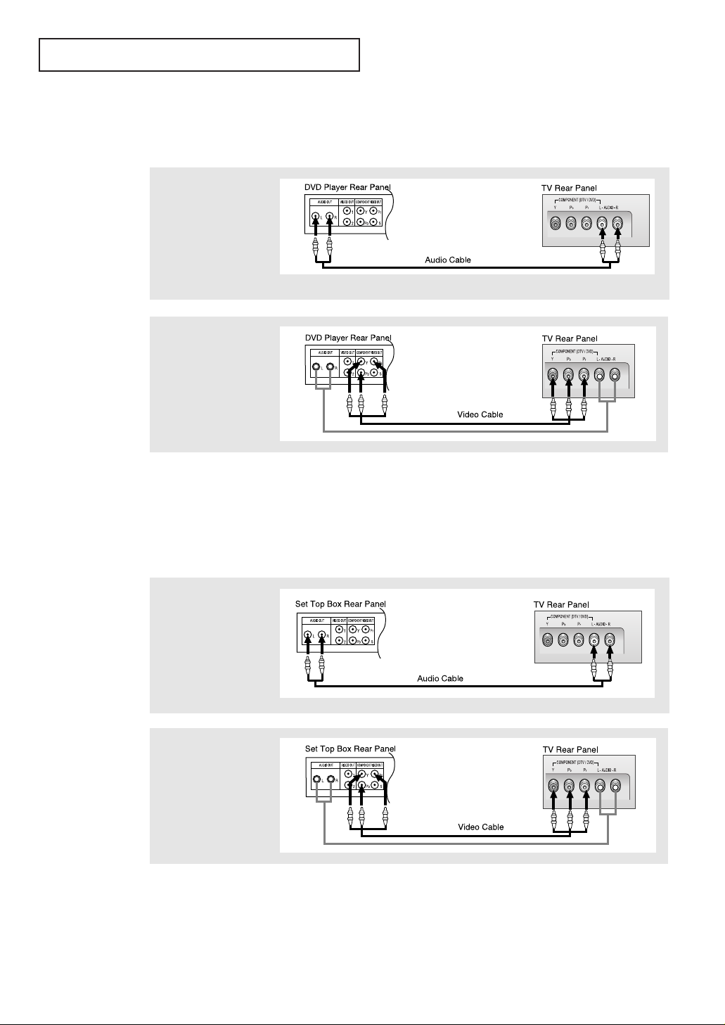
Note: For an explanation of Component video, see your DVD player owner's manual.
Connecting a DVD Player
The rear panel jacks on your TV make it easy to connect a DVD player to your TV.
1
Connect a set of audio
cables between the L, R
COMPONENT AUDIO
INPUT jacks on the TV
and the AUDIO OUT jacks
on the DVD player.
2
Connect a video cable
between the COMPONENT: DVD/DTV (Y, Pb,
Pr) jacks on the TV and
the Y, Pb, Pr jacks on the
DVD player.
Note: For an explanation of Component video, see your Set-Top Box owner's manual.
Connecting a Digital TV Set-Top Box
The connections for a typical set-top box are shown below.
1
Connect a set of audio
cables between the L, R
COMPONENT DVD/DTV
AUDIO INPUT jacks on
the TV and the AUDIO
OUT jacks on the Set-Top
Box.
2
Connect a video cable
between the COMPONENT: DVD/DTV (Y, Pb,
Pr) jacks on the TV and
the Y, Pb, Pr jacks on the
Set-Top Box.
Page 19
ENG 2.8
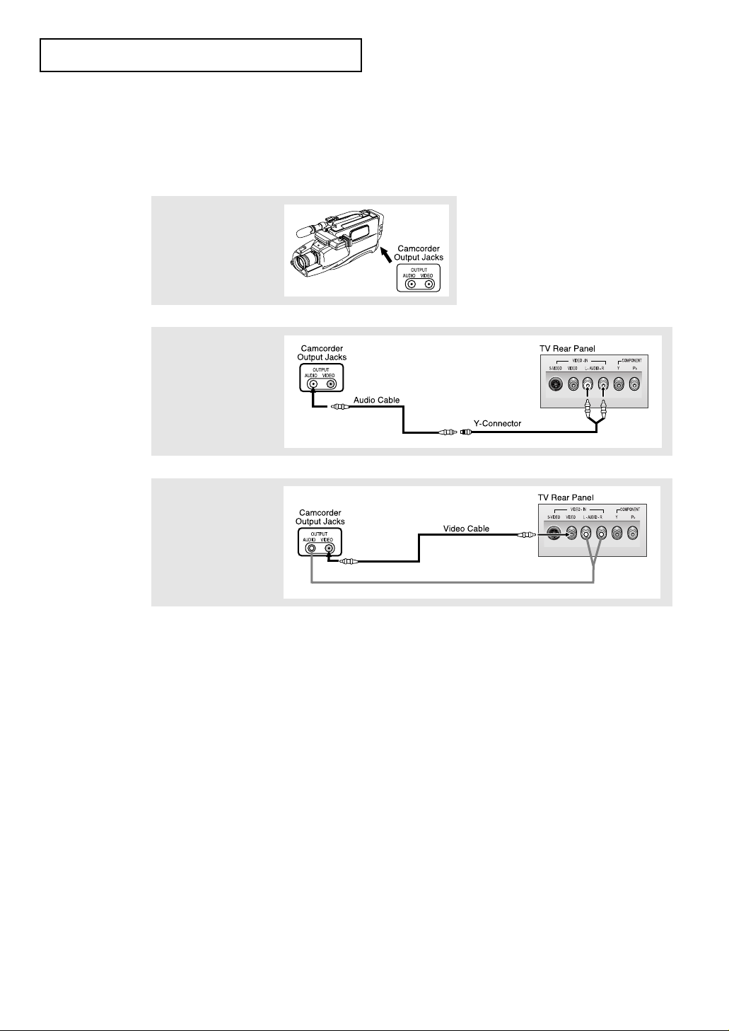
2
Connect an audio cable
between the AUDIO
OUTPUT jack on the
camcorder and the
AUDIO terminals on the
back of the TV.
3
Connect a video cable
between the VIDEO
OUTPUT jack on the
camcorder and the
VIDEO terminal on the
back of the TV.
1
Locate the A/V output
jacks on the camcorder.
They are usually found on
the side or back of the
camcorder.
Connecting a Camcorder
The connections for a camcorder are shown below.
They allow you to view the camcorder tapes without using a VCR. (Also see “Viewing a
VCR or Camcorder Tape” on page 3.14)
The audio-video cables shown here are usually included with a Camcorder. (If not, check
your local electronics store.) If your camcorder is stereo, you need to connect a set of two
cables.
INSTALLATION
Page 20
ENG 2.9
INSTALLATION
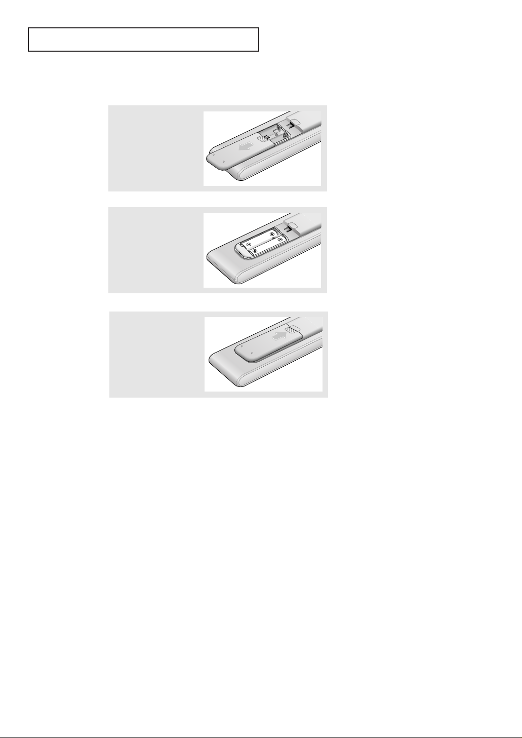
▼
3
Replace the cover.
Remove the batteries and store
them in a cool, dry place if you won’t
be using the remote control for a
long time.
The remote control can be used up
to about 23 feet from the TV.
(Assuming typical TV usage, the batteries last for about one year.)
▼
2
Install two AAA size
batteries.
Make sure to match the “
+” and
“
–” ends of the batteries with the
diagram inside the compartment.
Installing Batteries in the Remote Control
1
Slide the cover out
completely.
Page 21

ENG 3.1
Chapter 3
OPERATION
Turning the TV On and Off
Press the POWER button.
You can also use the Power button on the front panel.
Plug & Play Feature
When the TV is initially powered On, two basic customer settings proceed automatically
and subsequently: Setting Auto program, Clock.
1
Press the POWER button
on the remote control.
The message “Plug &
Play” is displayed.
It flickers for a little while,
then the “Language”
menu is automatically displayed.
2
Press the VOL+ or VOL-
button to select the
desired language.
Press the MENU button to
enter the language, and
then the “Time” menu is
automatically displayed.
3
Press the VOL+ or VOL-
buttons to move to the
hour or minute. Set the
hour or minute by pressing the CH▲ or CH▼ buttons. (refer to “Setting the
clock” on page 3.9.)
Page 22

ENG 3.2
OPERATION
4
Press the VOL+ or VOL-
button to select the
desired video signal
source.
Press the MENU button to
enter the video signal
source, and then the
“Ant Input check” is
automatically displayed.
5
Make sure that the
antenna is connected to
the TV. Press the VOL+ or
VOL- button to activate
"Auto Program" or
press the MENU button to
skip. (refer to “Auto
program” on page 3.6.)
6
The message “Enjoy your
watching.” is displayed.
7
If you want to reset this feature
(1) Press the MENU button.
(2) Press the CH▼ button to
highlight the Function
menu and press the
VOL+ button.
(3) Press the CH▼ button to
select Plug & Play and
press the VOL+ button.
The message “Plug &
Play” is displayed.
Enjoy your Watching.
Page 23

ENG 3.3
OPERATION
Viewing the Display
The display identifies the current channel and the status
of certain audio-video settings.
▼
The on-screen displays
disappear after about ten seconds.
Viewing the Menus and On-Screen Displays
Viewing the Menus
▼
1
With the power on, press
the MENU button.
The main menu appears
on the screen. Its left side
has five icons: Picture,
Sound, Channel, Function
and PC.
The on-screen menus disappear
from the screen after about thirty
seconds.
▼
You can also use the MENU,
CHANNEL, and VOLUME buttons
on the control panel of the TV to
make selections.
1
Press the Display button
on the remote control.
The TV will display the
channel, the type of
sound, and the status of
certain picture and sound
settings.
2
Use the CH▲ and CH▼ buttons to select one of the 5 icons.
Then press VOL+ to access the icon’s sub-menu.
3
Press the MENU button to exit.
Page 24

ENG 3.4
OPERATION
Selecting a Menu Language
3
Press the VOL + button to select the appropriate language:
English, Spanish, French or Portuguese.
4
Press the MENU button to exit.
2
Press the CH ▼ button to
select Language.
1
Press the MENU button to
display the menu.
Press the CH ▼ button to
select “Function”, then
press the VOL + button.
Page 25

ENG 3.5
OPERATION
Memorizing the Channels
Your TV can memorize and store all of the available channels for both “off-air” (antenna)
and cable channels. After the available channels are memorized, use the CH ▲ and
CH ▼ buttons to scan through the channels. This eliminates the need to change channels
by entering the channel digits. There are three steps for memorizing channels: selecting a
broadcast source, memorizing the channels (automatic) and adding and deleting channels
(manual).
Selecting the Video Signal-source
Before your television can begin memorizing the available channels, you must specify the
type of signal source that is connected to the TV (i.e., an antenna or a cable system).
1
Press the MENU button to
display the menu.
Press the CH ▼ button to
select “Channel”, then
press the VOL + button.
2
Repeatedly press the
VOL + button to cycle
through these choices:
ANT (antenna), STD, HRC
or IRC (all cable TV).
Note: STD, HRC and IRC identify various types of cable TV
systems. Contact your local cable company to identify the type
of cable system that exists in your particular area.
At this point the signal source has been selected. Proceed to
“Storing Channels in Memory” (next page).
Page 26

ENG 3.6
3
Press the VOL + button.
The TV will begin
memorizing all of the
available channels.
OPERATION
Storing Channels in Memory (Automatic Method)
▼
The TV automatically cycles
through all of the available channels
and stores them in memory. This
takes about one to two minutes.
Press VOL+ at any time to interrupt
the memorization process and return
to the CHANNEL menu.
2
Press the CH ▼ button to
select “Auto program”.
1
First, select the correct
signal source (ANT, STD,
HRC, IRC). See steps 1~2
on previous page.
Press the MENU button.
Press the CH ▼ button to
select “Channel”, then
press the VOL + button.
4
After all the available channels are stored, the Auto program
menu reappears. Press the MENU button to exit.
Page 27

ENG 3.7
OPERATION
Changing Channels
Using the Channel Buttons
1
Press the CH ▲ or CH ▼ buttons to change channels.
When you press the CH ▲ or CH ▼ buttons, the TV changes channels in
sequence. You will see all the channels that the TV has memorized. (The TV
must have memorized at least three channels.) You will not see channels that
were either erased or not memorized.
Directly Accessing Channels
Use the number buttons to quickly tune to any channel.
1
Press the number buttons to go directly to a channel.
For example, to select channel 27, press “2,”then “7.” The TV will change channels
when you press the second number.
When you use the number buttons, you can directly select channels that were
either erased or not memorized.
To select a channel over 100, press the +100 button. (For channel 122, press
“+100,” then “2,” then “2.”)
To change to single-digit channels (0–9) faster, press “0” before the
single digit. (For channel “4,” press “0,” then “4.”)
2
Press the ADD/ERASE button.
Repeatedly pressing this button will alternate between “Added” and “Erased.”
You can view any channel (including an erased channel) by using the number
buttons on the remote control.
1
Use the number buttons to directly select the channel that will be added or erased.
Adding and Erasing Channels (Manual Method)
Using the Pre-CH Button to select the Previous Channel
1
Press the PRE-CH button.
The TV will switch to the last channel viewed.
To quickly switch between two channels that are far apart, tune to one channel,
then use the number button to select the second channel. Then, use the PRE-CH
button to quickly alternate between them.
Page 28

ENG 3.8
OPERATION
Adjusting the Volume
1
Press the VOL + or VOL – buttons to increase or decrease the volume.
1
Press MUTE and the sound cuts off.
The word “Mute” will appear in the lower-left corner of the screen.
2
To turn mute off, press the MUTE button again, or simply
press either the VOL + or VOL – button.
Using Mute
At any time, you can temporarily cut off the sound using the Mute button.
Page 29

ENG 3.9
OPERATION
Setting the Clock
Setting the clock is necessary in order to use the various timer features of the TV.
Also, you can check the time while watching the TV. (Just press DISPLAY.)
1
Press the MENU button to
display the on-screen
menu.
Press the CH ▼ button
three times to select
“Function”, then press
the VOL + button.
3
Press the VOL + button.
Press the CH ▲ or CH ▼
buttons repeatedly until
the correct hour appears.
After the hour is entered,
press the VOL + button.
2
Press the CH ▼ button to
select “Time”, then press
the VOL + button.
4
Press the VOL + button
again. Press the CH ▲ or
CH ▼ buttons repeatedly
until the correct minutes
appear.
After the minutes are
entered, press the VOL +
button.
Press the MENU button to
exit.
▼
When selecting the hours, be sure
to select the proper time of day (AM
or PM).
You can change the hours by pressing
the CH ▲ or CH ▼ buttons repeatedly (or by holding down either of these
buttons).
The time will appear every time you
press the Display button.
Page 30

ENG 3.10
OPERATION
1
Press the MENU button to
display the menu.
Press the VOL + button to
display the Picture menu.
Customizing the Picture
You can use the on-screen menus to change the contrast, brightness, sharpness, color,
tint and color tone according to personal preference. (Alternatively, you can use one
of the “automatic” settings. See next page.)
2
Press the CH ▼ or CH ▲
buttons to select a
particular item.
3
Press the VOL + or VOL –
buttons to increase or
decrease the value of a
particular item.
For example, if you select
“Contrast,” pressing
VOL + increases it.
Press the MENU button to
exit.
▼
When Color Tone is selected you
can choose between “Normal”, “Warm”,
or “Cool” according to personal preference.
Page 31

ENG 3.11
OPERATION
Using Automatic Picture Settings
Your TV has two automatic picture settings (“Standard”, “Mild” and “Dynamic”) that are
preset at the factory. You can activate either Standard, Mild or Dynamic by pressing
P.STD (or by making a selection from the menu). Or, you can select “Custom” which
automatically recalls your personalized picture settings.
• Choose Standard for the standard factory settings.
• Choose Mild (“Mild Contrast”) when viewing the TV in low light, or when
playing video games.
• Choose Dynamic to increase the clarity and sharpness of the picture.
• Choose Custom if you want to adjust the settings accordings to personal
preference (see “Customizing the Picture, page 3.10).
1
Press the MENU button to
display the menu.
Press the VOL + button to
display the Picture menu.
2
Press the VOL +or VOL -
buttons to select the
“Standard,” “Mild,”
“Dynamic” or “Custom”
picture setting.
Alternate method:
Simply press the P.STD button on the remote control to
select one of the standard picture settings.
Page 32

ENG 3.12
OPERATION
2
Press the CH ▼ button to
select “Equalizer”, then
press the VOL+ button.
1
Press the MENU button to
display the menu.
Press the CH ▼ button to
select “Sound”, then
press the VOL+ button.
Customizing the Sound
The sound settings can be adjusted to suit your personal preference. (Alternatively, you
can use one of the “automatic” settings. See next page.)
3
Press the VOL – or VOL +
buttons to select a particular item to be changed.
Press the CH ▼ or CH ▲
buttons to increase or
decrease the value of a
particular item.
Press the MENU button to
exit.
Page 33

ENG 3.13
Using Automatic Sound Settings
Your TV has four automatic sound settings (“Standard,” “Music,” “Movie” and “Speech”)
that are preset at the factory. You can activate any of them by pressing the S.STD
button (or by making a selection from the on-screen menu). Or, you can select “Equalizer,”
which automatically recalls your personalized sound settings.
• Choose Standard for the standard factory settings.
• Choose Music when watching music videos or concerts.
• Choose Movie when watching movies.
• Choose Speech when watching a show that is mostly dialogue (i.e., news).
• Choose Custom to recall your personalized settings.
2
Press the VOL + or VOL -
buttons repeatedly to
select the “Standard,”
“Music,” “Movie,”
“Speech” or “Custom”
sound setting.
1
Press the MENU button to
display the menu.
Press the CH ▼ button to
select “Sound”, then
press the VOL+ button.
OPERATION
Alternate method:
Simply press the the S.STD button on the remote control to
select one of the standard sound settings.
Page 34

ENG 3.14
OPERATION
Viewing a VCR or Camcorder Tape
You must select the appropriate mode in order to view the VCR or Camcorder signal on
the TV.
1
Press the MENU button to
display the menu.
Press the CH ▼ button to
select “Channel”, then
press the VOL+ button.
2
Press the CH ▼ button to
select “TV/Video”.
3
Press the VOL+ or VOL-
button.
You will switch between
viewing the signals coming from equipment connected to the TV’s A/V
jacks, and the TV signal.
▼
Quick way to access the external
signal: Simply press the TV/VIDEO
button on the remote control.
Page 35

ENG 4.1
Fine Tuning Channels
Use fine tuning to manually adjust a particular channel for optimal reception.
1
Select the appropriate
channel.
2
Press the MENU button to
display the menu.
Press the CH ▼ button
twice to select “Channel”,
then press the VOL + button.
3
Press the CH ▼ button to
select “Fine Tune.”
4
Press the VOL + and VOL –
buttons to adjust the fine
tuning.
5
To store the fine tuning
setting in the TV’s memory, press the CH ▲ button.
(A heart icon will appear.)
To reset the fine tuning to
“00,”press the CH ▼ button.
Press the MENU button to
exit.
▼
After you adjust the fine tuning,
the “heart icon” will appear when
you press Display while watching
this channel.
Chapter 4
SPECIAL F EATURES
Page 36

ENG 4.2
S
PECIAL F EATURES
LNA (Low Noise Amplifier)
If the TV is operating in a weak-signal area, sometimes the LNA function can improve
the reception (a low-noise preamplifier boosts the incoming signal).
2
Press the CH ▼ button to
select “LNA.”
3
Press the VOL + or VOL -
button to set LNA “On.”
Press the MENU button to
exit.
1
Press the MENU button to
display the menu.
Press the CH ▼ button to
select “Channel”, then
press the VOL + button.
Pressing VOL - or VOL + will alter-
nate between “On” and “Off.”
▼
Page 37

ENG 4.3
SPECIAL
FEATURES
Setting the Blue Screen Mode
If no signal is being received or the signal is very weak, a blue screen automatically
replaces the noisy picture background.
If you wish to continue viewing the poor picture, you must set the “Blue screen”
mode to “Off”.
1
Press the MENU button to
display the menu.
Press the CH ▼ button to
select "Function", then
press the VOL + button.
2
Press the CH ▼ button to select "Blue
Screen."
3
Press the VOL + or VOL -
buttons to set Blue Screen
“On”.
Press the MENU button to
exit.
▼
Pressing the VOL- or VOL+ buttons will alternate between “On” and
“Off”.
Page 38

ENG 4.4
1
Press the STILL button to freeze the main picture.
• Not available if V-Chip is turned on.
• Normal sound will still be heard.
Press again to cancel.
SPECIAL
FEATURES
Freezing the Picture
Changing the Screen Size (DVD/DTV)
1
Press the P.SIZE button to change the screen size.
• Normal: Sets the picture to 4:3 normal mode.
This is a standard TV screen size.
• Zoom: Magnifies the size of the picture on screen.
Note: P.Size works in DVD/DTV mode.
Page 39

ENG 4.5
S
PECIAL F EATURES
Special Sound Options
Setting Multi-channel Soundtrack (MTS)
When MTS is set to “Auto”, MTS will be set automatically to "Mono" or "Stereo", according to the signal transmitted from the broadcasting company. If a channel is selected in
an area where reception is poor, the sound might be distorted. When this occurs, set
MTS Setting to "Manual" and MTS to "Mono".
2
Press the CH▼ button
five times to select
“MTS Setting”.
3
Press the VOL + button
repeatedly to select
“Manual” or “Auto.”
Press the MENU button to
exit.
1
Press the MENU button to
display the menu.
Press the CH▼ button to
select “Sound”, then
press the VOL + button
Page 40

ENG 4.6
SPECIAL
FEATURES
Choosing a Multi-Channel Soundtrack (MTS)
Depending on the particular program being broadcast, you can listen to stereo, mono, or
a Separate Audio Program. (SAP audio is usually a foreign-language translation. Sometimes SAP has unrelated information like news or weather.)
2
Press the CH▼ button
five times to select
“MTS”.
3
Press the VOL + button
repeatedly to select
“Mono,” “SAP,” or
“Stereo.”
Press the MENU button to
exit
▼
The text at the bottom of the
menu tells you if the incoming
audio is stereo, SAP, or mono.
1
Press the MENU button to
display the menu.
Press the CH▼ button to
select “Sound”, then
press the VOL + button
• Choose Stereo for channels that are broadcasting in stereo.
• Choose Mono for channels that are broadcasting in mono, or if you are having
difficulty receiving a stereo signal.
• Choose SAP to listen to the Separate Audio Program, which is usually a foreign-language
translation.
You can also change the MTS setting by pressing the “MTS” button on the remote control.
(When you change channels, MTS is set to “Stereo” automatically. To listen in ‘SAP’ or ‘Mono,’
change the MTS setting.)
Page 41

ENG 4.7
SPECIAL
FEATURES
Auto Volume
Each broadcasting station has its own signal conditions, and it is inconvenient to adjust
the volume every time the channel is changed. “Auto volume” automatically adjusts the
volume of the desired channel by lowering the sound output when the modulation signal is high or by raising the sound output when the modulation signal is low.
2
Press the CH▼ button to
select “Auto volume”.
3
Press the VOL + button to
select “On”.
Press the MENU button to
exit.
1
Press the MENU button to
display the menu.
Press the CH▼ button to
select “Sound”, then
press the VOL + button
Pressing VOL - or VOL + will alter-
nate between “On” and “Off.”
▼
Page 42

ENG 4.8
SPECIAL
FEATURES
Virtual Dolby
This feature allows the TV’s L/R speakers to provide a home Theater-like Dolby effect.
The center and surround sounds are mixed into the L/R speakers.
2
Press the CH▼ button to
select “Virtual Dolby”.
3
Press the VOL + button to
select “On”.
Press the MENU button to
exit.
1
Press the MENU button to
display the menu.
Press the CH▼ button to
select “Sound”, then
press the VOL + button
Pressing VOL - or VOL + will alter-
nate between “On” and “Off.”
▼
▼
Quick way to access the Virtual
Dolby menu: Simply press the
V.DOLBY button on the remote
control.
Page 43

ENG 4.9
SPECIAL
FEATURES
▼
Note: Sound Select can
also be used to select the Main
or Sub sound over the speakers.
Selecting the Headphone Sound
You can select either Main or Sub when PIP is On.
1
Press the MENU button to
display the menu.
Press the CH▼ button to
select “Sound”, then
press the VOL + button
2
Press the CH▼ button to
select “Sound Select”.
3
Press the VOL + button to
select “Main” or “Sub”.
Select “Main” to hear the
main TV sound and select
“Sub” to hear the PIP window sound.
Press the MENU button to
exit.
Page 44

ENG 4.10
SPECIAL F EATURES
Setting the On/Off Timer
1
Press the MENU button to
display the on-screen
menu.
Press the CH ▼ button
three times to select
“Function”, then press
the VOL + button.
▼
Before using the timer, you must
set the TV’s clock. (See “Setting the
Clock” on page 3.9)
2
Press the CH ▼ button to
select “Time”, then press
the VOL + button.
3
Press the CH ▼ button to
select “On time”, then
press the VOL + button.
Press the CH ▲ or CH ▼
buttons repeatedly to
select the appropriate
hours (i.e., the hour when
the TV will turn on.)
▼
When you set the hours, make
sure the correct time of day (AM or
PM) appears to the left of the hour.
4
Press the VOL + button to
select the “On time” minutes.
Press the CH ▲ or CH ▼
buttons repeatedly to
select the appropriate
minutes.
continued...
Page 45

ENG 4.11
S
PECIAL F EATURES
5
Press the VOL + button to
select “On/Off.”
Press the CH ▲ or CH ▼
buttons to turn the ontimer “On.” (Repeatedly
pressing the CH ▲ or
CH ▼ buttons will alter-
nate between on and off.)
When finished, press the
VOL + button.
▼
To deactivate the “On time,”
select “Off” during this step.
6
To set the Off time, press
the CH ▼ button to select
“Off time.”
Press the VOL + button
and set the hours and
minutes. (Follow the same
procedure as in steps 1~5
above.)
7
When finished setting the timer, press the MENU button to
exit.
1
Press the SLEEP button on the remote control.
2
Press SLEEP repeatedly until the appropriate time interval
appears (any of the preset values from “Off” to “360”).
▼
After about 5 seconds, the sleep
display will disappear from the
screen, and the time interval will be
set.
Setting the Sleep Timer
The sleep timer automatically shuts off the TV after a preset time
(from 10 to 180 minutes).
Page 46

ENG 4.12
S
PECIAL F EATURES
▼
Misspellings and unusual
characters sometimes occur during
closed caption transmissions, especial-
ly those of live events. There may be a
small delay before captions appear
when you change channels. These are
not malfunctions of the TV.
3
Press the VOL+ or VOL –
buttons to turn closed
captioning on/off.
▼
In caption mode, captions
appear at the bottom of the screen,
and they usually cover only a small
portion of the picture.
In text mode, information unrelated
to the program, such as news or
weather, is displayed. Text often
covers a large portion of the screen.
4
Press the CH ▼ button to
select “Mode.”
Press the VOL + or VOL –
buttons to select “Caption” or “Text.”
Viewing Closed Captions
Your TV decodes and displays the closed captions that are broadcast with certain TV shows.
These captions are usually subtitles for the hearing impaired or foreign-language translations. All VCRs record the closed caption signal from television programs, so home-recorded
video tapes also provide closed captions. Most pre-recorded commercial video tapes provide
closed captions as well. Check for the closed caption symbol in your television schedule and
on the tape’s packaging: .
Note: The Caption feature does not work with PC, DVD and DTV signals.
1
Press the MENU button to
display the menu.
Press the CH ▼ button to
select “Function”, then
press the VOL+ button.
2
Press the CH ▼ button to
select “Caption”, then
press the VOL+ button.
▼
5
Depending on the particular broadcast, it might be necessary to
make changes to “Channels” and “Field”:
Use the CH ▲, CH ▼, VOL + and VOL - buttons to make the
changes. (Follow the same procedure as in steps 3~4 above.)
Press the MENU button to exit.
Different channels and fields
display different information: Field 2
carries additional information that
supplements the information in
Field 1. (For example, Channel 1
may have subtitles in English, while
Channel 2 has subtitles in Spanish.)
▼
Quick way to access the Caption
menu: Simply press the CAPTION
button on the remote control.
Page 47

ENG 4.13
SPECIAL F EATURES
Viewing Picture-in-Picture
You can use the PIP feature to simultaneously watch two video sources.
Note: While V-Chip is in operation, PIP function cannot be used.
If PIP does not operate, please check whether V-chip is in operation.
PIP works in PC mode and DVD/DTV mode.
Activating Picture-in-Picture
1
Press the MENU button to
display the menu.
Press the CH▼ to select
“PIP”, then press the
VOL + button.
2
Press the VOL + button to
select PIP “On.”
▼
If you turn the TV off while
watching and turn it on again, the PIP
window will disappear.
3
Press the MENU button to exit.
▼
Quick way to access the PIP
menu: Simply press the PIP button
on the remote control.
PIP Settings
Page 48

ENG 4.14
SPECIAL F EATURES
Press the TV/VIDEO(PIP) button repeatedly to cycle through
all of the available signal sources: “RF”, “Video”, “S-Video”.
▼
For more information about
external A/V components and signals, see “Viewing a VCR or Camcorder Tape” on page 3.14.
If you select “TV”, the PIP image is
the same as the main image.
When you press the SWAP button,
the “Not available” screen will appear.
Swapping the Contents of the PIP image and Main image
Selecting a Signal Source (External A/V) for PIP
Press the PIP CH▲ or CH▼ button to change the channel
that appears in the PIP window.
Changing the PIP Channel
When you press the LOCATE button repeatedly, the PIP window moves from corner to corner on the TV screen.
Changing the Location of the PIP Window
When you press the SIZE button, the “Not available” screen
will appear.
Changing the Size of the PIP Window
Page 49

ENG 4.15
Using the V-Chip(US only)
The V-Chip feature automatically locks out programming that is deemed inappropriate for
children. The user must first enter a PIN (personal ID number) before any of the V-Chip
restrictions can be set up or changed.
Note: While V-Chip is in operation, PIP function cannot be used.
If PIP does not operate, please check whether V-chip is in operation.
Setting Up Your Personal ID Number (PIN)
1
Press the MENU button to
display the menu.
Press the CH ▼ button to
select “Function”, then
press the VOL + button.
2
Press the CH ▼ button to
select “V-chip”, then
press the VOL+ button.
3
After entering a valid PIN
number, the “V-chip”
screen will appear.
Press the CH ▼ button to
select “Change Pin.”
V-Chip Lock Yes
TV GuideLines
MPAA Rating
Change Pin
4
Press the VOL+ button.
The Change pin screen
will appear. Choose any
4-digits for your PIN and
enter them.
Note: If you forget the PIN,
press the remote-control buttons in
the following sequence, which resets
the pin to 0-0-0-0:
POWER OFF ➜ MUTE ➜ 8 ➜ 2 ➜
4 ➜ POWER ON.
▼
SPECIAL F EATURES
As soon as the 4 digits are entered, the “Confirm new Pin”
screen appears. Re-enter the same 4 digits. When the Confirm screen disappears, your PIN has been memorized.
Press the MENU button to exit.
The “Enter Pin” screen will appear. Enter your 4-digit PIN
number. Note: The default PIN number for a new TV set is
“0-0-0-0.”
Quick way to access the V.CHIP
menu: Simply press the V.CHIP
button on the remote control.
▼
➜
Page 50

ENG 4.16
How to Set up Restrictions Using the “TV guidelines”
First, set up a personal identification number (PIN), and enable the V-Chip. (See previous
section.) Parental restrictions can be set up using either of two methods: The TV guidelines or the MPAA rating.
How to Enable/Disable the V-Chip
Note: V-Chip cannot be used during PIP operation.
1
Press the MENU button to
display the menu.
Press the CH ▼ button to
select “Function”, then
press the VOL + button.
2
Press the CH ▼ button to
select “V-chip”, then
press the VOL+ button.
The “Enter pin” screen
will appear. Enter your 4digit PIN number.
3
The “V-Chip” screen will
appear, and “V-Chip lock”
will be select.
To enable the V-Chip feature,
press the VOL+ button so
that the “V-Chip Lock” is set
to Yes.
(Pressing the VOL+ button
will alternate between Yes
and No.)
1
Press the MENU button to
display the menu.
Press the CH ▼ button to
select “Function”, then
press the VOL + button.
SPECIAL F EATURES
Page 51

ENG 4.17
2
Press the CH ▼ button to
select “V-chip”, then
press the VOL+ button.
The “Enter pin” screen
will appear. Enter your 4digit PIN number.
3
Press the CH ▼ button, to
select “TV Guidelines”,
then press the VOL+ button.
4
The “TV guidelines”
screen will appear.
Press the the CH ▲, CH ▼
buttons to select one of
the six age-based categories:
TV-Y Young children
TV-Y7 Children 7 and over
-------------------------------------TV-G General audience
TV-PG Parental guidance
TV-14 Viewers 14 and over
TV-MA Mature audience
5
At this point, one of the TV-Ratings is selected.
Press the VOL + button: Depending on your existing setup, a letter “U” or “B” will start blinking.
(U= Unblocked, B= Blocked)
While the “U” or ”B” is blinking, press the CH ▲ or CH ▼ buttons to block or unblock the category.
Press the MENU button once to save the TV guidelines. A TV-Rating will be highlighted, and no letters will blink.
To exit this screen, press the MENU again. To select a different TV-Rating, press the CH ▲ or CH ▼ buttons and
then repeat the process.
Note 1: The TV-Y7, TV-PG, TV-14 and TV-MA have additional options. See the next step to change any of the
following sub-ratings:
FV: Fantasy violence
D: Sexual suggestive dialog
L: Adult language
S: Sexual situation
V: Violence
Note 2: The V-Chip will automatically block certain categories that are “more restrictive.” For example, if you block
“TV-Y” category, then TV-Y7 will automatically be blocked. Similarly, if you block the TV-G category, then all the
categories in the “young adult” group will be blocked (TV-G, TV-PG, TV-14 and TV-MA). The sub-ratings (D, L, S, V)
work together similarly. (See next section.)
Note: These categories consist of
two separate groups: TV-Y and TV-Y7
(young children through age 7), and
TV-G through TV-MA (everybody
else).
The restrictions for these two groups
work independently: If a household
includes very young children as well
as young adults, the TV guidelines
must be set up separately for each age
group. (See next step.)
▼
SPECIAL F EATURES
Page 52

ENG 4.18
How to Set up Restrictions using the MPAA Ratings: G, PG, PG13, R, NC-17, X
The MPAA rating system uses the Motion Picture Association of America (MPAA) system, and
its main application is for movies. (Eventually, movie videocassettes will be encoded with
MPAA ratings.) When the V-Chip lock is on, the TV will automatically block any programs
that are coded with objectionable ratings (either MPAA or TV-Ratings).
6
How to set the FV, D, L, S and V sub-ratings.
First, highlight one of these TV-Ratings: TV-Y7, TV-PG, TV-14 or TV-MA (See Step 4, on previous page).
Next, while the TV-Rating is selected, repeatedly press the VOL+ button. This will cycle through the available sub-ratings (FV,L, S, D or V).
A blinking letter (“U” or “B”) will be displayed for each sub-rating. While the “U” or “B” is blinking, press
the CH ▲ or CH ▼ buttons to change the sub-rating.
Press MENU once to save the TV guidelines. A TV-Rating will be selected, and no letters will blink. To exit
this screen, press the MENU button again. To select a different TV-Rating, press the CH ▲ or CH ▼ buttons
and then repeat the process.
Note: The V-chip will automatically block certain categories that are “More restrictive”. For example, if you
block “L” sub-rating in TV-PG, then the “L” sub-ratings in TV-14 and TV-MA will automatically be blocked.
7
Press the MENU button three times to clear all the screens. (Or proceed to the next section, and set up
additional restrictions based on the MPAA codes).
1
Press the MENU button to
display the menu.
Press the CH ▼ button to
select “Function”, then
press the VOL + button.
2
Press the CH ▼ button to
select “V-chip”, then
press the VOL+ button.
The “Enter pin” screen
will appear. Enter your 4digit PIN number.
SPECIAL F EATURES
Page 53

ENG 4.19
How to Reset the TV after the V-Chip
Blocks a Channel (“Emergency Escape”)
If the TV is tuned to a restricted channel, the V-Chip will block it. The screen will go blank and the following
message will appear: “Excessive rating.”
To resume normal viewing, tune to a different channel using the number buttons. Under certain conditions
(depending on the rating of the local TV programs) the V-Chip might lock out all the channels.
In this case, use the V.Chip button for an “emergency escape”:
Press the V.chip button on the remote control. Enter your PIN number, and press the VOL + button to temporarily disable the V-Chip Lock.
4
Repeatedly press the CH
▼ button to select a particular MPAA category.
(When a category is
selected, its color
changes to blue.) Pressing
the CH ▼ button will cycle
through the MPAA categories:
G General audience (no restrictions).
PG Parental guidance suggested.
PG-13 PG-13 (Parents strongly cautioned).
R R (Restricted. Children under 17 should
be accompanied by an adult).
NC-17 No children under age 17.
X X (Adults only).
NR Not rated.
3
Press the CH ▼ button to
select “MPAA rating”,
then press the VOL + button.
SPECIAL F EATURES
While a particular category is highlighted, press the VOL+ button to activate it.
A blinking letter (“U” or “B”) will be displayed. Press the CH ▲ or CH ▼ buttons to
select “U” or”B”.
Press the MENU button three times to save the settings and to clear all screens.
Note: The V-Chip will automatically block any category that is “more restrictive.”
For example, if you block the “PG-13” category, then “R,” “NC-17,” and “X” will automatically be blocked also.
Page 54

ENG 5.1
Chapter 5
PC DISPLAY
Using Your TV as a Computer (PC) Display
How to Connect Your PC to the TV
Note: This figure shows the Standard Connector-jack panel. The actual configuration on
your TV may be different, depending on the model.
• PC AUDIO INPUT
Connect these to the audio-output jacks on your PC.
• PC VIDEO INPUT
Connect to the video output port on your PC.
TV rear panel PC rear
Page 55

ENG 5.2
PC DISPLAY
How to Set up Your PC Software (Windows only)
The Windows display-settings for a typical computer are shown below. However, the actual screens on your PC will probably look different, depending upon your particular version
of Windows and your particular video card. Even if your actual screens look different, the
same, basic set-up information will apply in most cases. (If not, contact your computer
manufacturer or Samsung Dealer.)
First, click on “Settings” on the Windows start menu.
While “Settings” is highlighted, move
the cursor so that “Control Panel” is
highlighted.
When the control panel screen
appears, click on “Display” and a display dialog-box will appear.
Navigate to the “settings” tab on the
display dialog-box.
The two key variables that apply the TVPC interface are “resolution” and “colors.” The correct settings for these two
variables are:
* Size (sometimes called “resolution”):
1024 x 768 pixels
If a vertical-frequency option exists on
your display settings dialog box, the correct value is “60” or “60 Hz.” Otherwise,
just click “OK” and exit the dialog box.
Page 56

ENG 5.3
Adjusting the Screen Quality
The purpose of picture quality adjustment is to remove or reduce picture noise. If the
noise is not removed by fine tuning alone, then do the frequency adjustments to the
utmost and fine tune again. After the noise has been reduced, re-adjust the picture so
that it is aligned on the center of screen
Press the PC button on the remote control to select the PC mode.
1
Press the MENU button to
display the menu.
Press the CH ▼ button to
select “PC”, then press
the VOL + button.
2
Press the CH ▼ button to
select “Coarse” or “Fine”.
3
Press the VOL + or VOL -
button to adjust the
screen quality, vertical
stripes appear or the picture may be blurry.
4
When you are satisfied with the settings, press the MENU button repeatedly to return to normal viewing.
PC DISPLAY
<Adjusting the Coarse>
<Adjusting the Fine>
Page 57

ENG 5.4
Changing the Screen Position
Press the PC button on the remote control to select the PC mode.
To Return the Screen Position settings to the default position
1
Press the MENU button to
display the menu.
Press the CH ▼ button to
select “PC”, then press
the VOL + button.
Press the CH ▼ button to
select “Image Recall”,
then press the VOL + button to return H and V positions to their default settings.
2
Press the CH ▼ button to
select “H-Position” or
“V-Position”.
3
Press the VOL + or VOL -
button to adjust the
required position.
Press the MENU button to
exit.
PC DISPLAY
<Adjusting the H-Position>
<Adjusting the V-Position>
Page 58

ENG 5.5
PC DISPLAY
Changing the Screen Color Standard
Press the PC button on the remote control to select the PC mode.
1
Press the MENU button to
display the menu.
Press the CH ▼ button to
select “PC”, then press
the VOL + button.
2
Press the CH ▼ button to
select “Color Adjust”.
3
Press the VOL +or VOL -
buttons to select
“Custom”, “Color1”,
“Color2” or “Color3”.
Press the MENU button to
exit.
Page 59

ENG 5.6
Adjusting the Screen Color Settings
Press the PC button on the remote control to select the PC mode.
To Return the Custom settings back to the default position
1
Press the MENU button to
display the menu.
Press the CH ▼ button to
select “PC”, then press
the VOL + button.
Press the CH ▼ button to
select “Color Recall”, then
press the VOL + button to
return R,G,B to their
default settings.
2
Press the CH ▼ button to
select “Color Adjust”,
then press the VOL + button.
Repeatedly press VOL + to
choose between Color 1,2,
and 3 auto settings and
Custom.
3
If Custom is selected,
press the CH ▼ or CH ▲
button to select the item
you want to adjust, then
press the VOL + or VOL -
button to adjust the
color(R, G, B).
Press the MENU button to
exit.
PC DISPLAY
Page 60

ENG 6.1
If the TV seems to have a problem, first try this list of possible problems and solutions.
If none of these troubleshooting tips apply, call your nearest service center.
Identifying Problems
Chapter 6
TROUBLESHOOTING
Problem
Poor picture
Poor sound quality.
No picture or sound.
No color, wrong colors or
tints.
Picture rolls vertically.
The TV operates erratically.
The TV won’t turn on.
Blurred or snowy picture,
distorted sound
Remote control malfunctions
“Check Signal Cable”
message.
Possible Solution
Tr y another channel.
Adjust the antenna.
Check all wire connections.
Tr y another channel.
Adjust the antenna.
Tr y another channel.
Press the TV/VIDEO button.
Make sure the TV is plugged in.
Check the antenna connections.
Make sure the program is broadcast in color.
Adjust the picture settings.
If the set is moved or turned in a different direction, the
power should be OFF for at least 30 minutes.
Adjust the antenna.
Check all wire connections.
Unplug the TV for 30 seconds, then try operating it
again.
Make sure the wall outlet is working.
Check the direction, location and connections of your
antenna.
This interference is often due to the use of an indoor
antenna.
Replace the remote control batteries.
Clean the upper edge of the remote control
(transmission window).
Check the battery terminals.
Ensure that the signal cable is firmly connected to the
PC or video sources.
Ensure that the PC or video sources are turned on.
Page 61

ENG 6.2
Problem
“Not Supported Mode!” mes-
sage.
The image is too light or too
dark.
Horizontal bars appear to
flicker, jitter or shimmer on
the image.
Vertical bars appear to flicker,
jitter or shimmer on the
image.
Screen is black and power
indicator light blinks steadily.
Image is not stable and may
appear to vibrate.
Image is not centered on the
screen.
Possible Solution
Check the maximum resolution and the frequency of
the video Adapter.
Compare these values with the data in the Display
Modes Timing Chart.
Adjust the Brightness and Contrast.
Adjust the Fine function.
Adjust the Coarse function and then adjust the Fine
function.
The TV is using its power management system.
Move the computer’s mouse or press a key on the
keyboard.
Check that the display resolution and frequency from
your PC or video board is an available mode for your
TV. On your computer check: Control Panel, Display,
Settings.
If the setting is not correct, use your computer utility
program to change the display settings.
NOTE: Your TV supports multiscan display functions
within the following frequency domain:
• Horizontal frequency: 30 kHz ~ 61 kHz
• Vertical frequency: 56 Hz ~ 75 Hz
• Maximum refresh rate: 1024 x 768 @ 60 Hz
Adjust the horizontal and vertical position.
TROUBLESHOOTING
Page 62

ENG A.1
Display Modes
If the signal from the system equals the standard signal mode, the screen is adjusted
automatically. If the signal from the system doesn’t equal the standard signal mode,
adjust the mode by referring to your Videocard user guide; otherwise there may be no
video. For the display modes listed below, the screen image has been optimized during
manufacture.
A
PPENDIX
Display Mode
Horizontal
Frequency
(kHz)
Vertical
Frequency
(Hz)
Pixel
Clock
Frequency
(MHz)
Sync Polarity
(H/V)
35.000
49.726
31.469
31.469
37.500
37.861
37.879
46.875
48.077
48.363
56.476
60.023
MAC, 640 ✕ 480
MAC, 832 ✕ 624
IBM, 640 ✕ 480
IBM, 720 ✕ 400
VESA, 640 ✕ 480
VESA, 640 ✕ 480
VESA, 800 ✕ 600
VESA, 800 ✕ 600
VESA, 800 ✕ 600
VESA, 1024 ✕ 768
VESA, 1024 ✕ 768
VESA, 1024 ✕ 768
66.667
74.551
59.940
70.087
75.000
72.809
60.317
75.000
72.188
60.004
70.069
75.029
30.240
49.500
25.175
28.322
31.500
31.500
40.000
49.500
50.000
65.000
75.000
78.750
-/ -
+ / +
-/ -
-
/ +
-
/
-
-
/
-
+ / +
+ / +
+ / +
-/ -
-
/
-
+ / +
Page 63

ENG A.2
APPENDIX
Retractable Stand
Note: The maximum tilt angle is 15 degrees in the backward direction. Please do not tilt
the TV outside the specified range. Using excessive force to tilt the LCD TV may cause
permanent damage to the mechanical part of the stand.
Using the Anti-Theft Kensington Lock
Figure 2
Figure 1
Cable
The Kensington lock is a device used to physically fix the system when using it in a public place. The locking
device has to be purchased separately. The appearance and locking method may differ from the illustration
depending on the manufacturer. Please refer to the manual provided with the Kensington lock for proper use.
1
Insert the locking device into the Kensington slot on the LCD TV(figure 1), and turn it in the locking
direction(figure 2).
2
Connect the Kensington lock cable.
3
Fix the Kensington lock to a desk or a heavy stationary object.
<Optional>
15
Page 64

ENG A.3
Pin Assignments
Pin D-Sub Connection
APPENDIX
Cleaning and Maintaining Your TV
With proper care, your TV unit will give you many years of service. Please follow these
guidelines to get the maximum performance from your TV.
Placement
• Do not place the TV near extremely hot, cold, humid or dusty places.
• Do not place the TV near appliances with electric motors that create magnetic fields,
such as vacuum cleaners.
• Keep the ventilation openings clear; do not place the TV on a soft surface, such as
cloth or paper.
• Place the TV in a vertical position only.
Liquids
• Do not handle liquids near or on the TV.
Liquids that spill into it can cause serious damage.
Cabinet
• Never open the cabinet or touch the parts inside.
•Wipe your TV with a clean, dry cloth. Never use water, cleaning fluids, wax, or
chemicals.
• Do not put heavy objects on top of the cabinet.
Temperature
• If your TV is suddenly moved from a cold to a warm place, unplug the power cord,
and allow at least two hours for moisture that may have formed inside the unit to dry
completely.
Using Your TV in Another Country
If you plan to take your TV with you to a foreign country, please be aware of the different
television systems that are in use around the world. A TV designed for one system may
not work properly with another system due to differences in the TV channel frequencies.
Pin
Separate
H/V
1234567 89101112131415
GND
GND
GND-
No
GND-Sync/
Red Green Blue GND GND
(DDC Return)
-Red
-Green
Blue
Connection
Self Test
GND DDC
H_Sync V_Sync
_SDA
DDC
_SCL
Page 65

ENG A.4
Model
Size
Display area
Pixel pitch
Type
Viewing angle
Synchronization
Display Colors
Resolution
Input signal, Terminated
Maximum pixel clock
Power supply
Signal cable
Signal connectors
Power consumption
Dimensions/Weight
(W X D X H)
Environmental considerations
Specifications
APPENDIX
LTM1525
15.0 inch diagonal
304.1(H) X 228.1(V) mm
0.297(H) X 0.297(V) mm
a-si TFT active matrix
70/70/55/60 (L/R/T/B)
Horizontal 30~61kHz
Vertical 56~75Hz
Non-interlaced
16,194,277 Colors
Optimum resolution : 1024 X 768 @60Hz
Maximum resolution : 1024 X 768 @75Hz
RGB Analog 0.7Vp-p Positive at 75Ω
Separate H/V sync, TTL level positive or negative
65MHz
AC 90 to 264 VAC, 60/50Hz ± 3Hz
DC 14V/3.5A
15pin to 15pin D-sub cable, Detachable
15pin 3-row D-sub connector, External TV tuner, Ypbpr, S-VHS, VCR
Max. 50W
346.0 x 169.0 x 361.5 mm / 3.2 kg (with Stand)
; 13.6 X 6.6 x 14.2 inches / 7.0 lbs (with Stand)
Operating Termperature : 50˚F to 104˚F (10˚c to 40˚c)
Humidity : 10% to 80%, Non-condensing
Storage Temperature : -4˚F to 113˚F (-20˚C to 45˚C)
Humidity : 5% to 95%, Non-condensing
* Referring to Preset timing modes, page A.1.
Page 66

BN68-00281K-00
 Loading...